


OPERATORS MANUAL

 WARNING:
ADHERE STRICTLY TO THESE AND ALL OTHER SAFETY INSTRUCTIONS AND GUIDELINES.
Warnings for safe Etek2 handling:
•The Etek2 is not a toy.
•Careless or improper use, including failure to follow instructions and warnings within this User Manual and attached to the Etek2 could cause death or serious injury.
•Do not remove or deface any warnings attached to the Etek2.
•Paintball industry standard eye/face/ear and head protection designed specifically to stop paintballs and meeting ASTM standard F1776 (USA) or CE standard (Europe) must be worn by user and any person within range.
•Persons under 18 years of age must have adult supervision when using or handling the Etek2.
•Observe all local and national laws, regulations and guidelines.
•Use only professional paintball fields where codes of safety are strictly enforced.
•Use compressed air/nitrogen only. Do not use Co2
•Always follow instructions, warnings and guidelines given with any first stage regulator you use with the Etek2.
•Use 0.68 calibre paintballs only.
•Keep the Etek2 switched off until ready to shoot.
• Treat every marker as if it is loaded.
• Never point the Etek2 at anything you do not intend to shoot. 


 WARNING
•Do not shoot at persons at close range.
•Always measure your markers velocity before playing paintball, using a suitable chronograph.
•Never shoot at velocities in excess of 300 feet (91.44 meters) per second, or at velocities greater than local or national laws allow.
•Do not fire the Etek2 without the bolt in the breech, as high-pressure gas will be emitted.
•Do not fire the Etek2 without the bolt pin locked securely in place.
•Never look into the barrel or breech area of the Etek2 whilst the marker is switched on and able to fire.
•Never put your finger or any foreign objects into the paintball feed tube of the Etek2.
•Never allow pressurised gas to come into contact with any part of your body.
•Always switch off the Etek2 when not in use.
•Always fit a barrel-blocking device to the Etek2 when not in use on the field of play.
•Always remove all paintballs from the Etek2 when not in use on the field of play.
•Always remove the first stage regulator and relieve all residual gas pressure from the Etek2 before disassembly.

 WARNING:
ADHERE STRICTLY TO THESE AND ALL OTHER SAFETY INSTRUCTIONS AND GUIDELINES.
•The Etek2 can hold a small residual charge of gas, typically 2 shots, with the first stage regulator removed. Always discharge the marker in a safe direction to relieve this residual gas pressure.
•Always remove the first stage regulator and relieve all residual gas pressure from the Etek2 for transport and storage.
•Always follow guidelines given with your first stage regulator for safe transportation and storage.
•Always store the Etek2 in a secure place.
NOTE: This user manual must accompany the product in the event of resale or new ownership. should you be unsure at any stage you must seek expert advice (See service centers)
• This Users Manual is in English.
• It contains important safety guidelines and Instructions.
•Should you be unsure at any stage, or unable to understand the contents within this manual you must seek expert advice.
•Le mode d'emploi est en Anglais.
•Ilcontient des instructions et mesures de sécu rité importantes.
•En cas de doute, ou s'il vous est impossible de comprendre le contenu du monde d'emploi, demandez conseil à un expert.
•ESTE MANUAL DE USUARIOS (oPERARIOS) usarios está en Inglés.
•Contiene importantes normas de seguridad e instrucciones.
•Si no está seguro de algùn punto o no entiende los contenidos de este manual debe consultar con un experto.
•Diese Bedienungs - und Benutzeranleitung ist in Englisch.
•Sie enthålt wichtige Sicherheitsrichtlinen und
- bestimmungen.
• Solten Sie sich in irgendeiner Weise un sicher sein. Oder den inhalte dies heftes nicht versthen, lassen Sie siche bitte von einen Experten beraten. 

VISIT WWW.PLANETECLIPSE.COM
WARNING 


6. ORIENTATION
This section names the component parts of the Etek2 Marker. This section is essential reading for everyone.
6. > GET TO KNOW YOUR Etek2
8. > THE Etek2 control CONSOLE
8. QUICK SET-UP
This section provides details on how to get up and running quickly with your Etek2. This section is essential reading for everyone.
8. > Installing a battery
9 > Switching On the Etek2.
9 > Switching Off the Etek2.
9 > Firing the Etek2.
9 > Using the Etek2 Break-Beam Sensor System
10. USING YOUR ETEK2
This section provides more detailed information on how to use and interact with the Etek2 via its user interface.
10 > Setting up
10 > Installing a Preset Air System
11 > T-SLOT MOUNTING SYSTEM
11> MACROLINE HOSING AND ELBOW
12> Installing an Adjustable Air System
13 > Attaching a loader
13 > Switching on
14 > THE CONTROL CONSOLE
14 > UNDERSTANDING THE BBSS OPERATION
15 > Adjusting YOUR Velocity
15 > Adjusting YOUR LPR Pressure
16. ADVANCED SET-UP
This section contains in-depth information on setting up the Etek2.
16> Setting the trigger
17> the tournament lock
18> The Set-Up Menu
19> Modifying A Parameter
20> the FIRING Mode Parameter
20 > Maximum Rate Of Fire (capped modes)
20 > Maximum Rate Of Fire (BBSS disabled)
21 > Dwell
21 > debounce
21 > the Ball Detection Time
21 > THE RESET PARAMETER
22. MAINTENANCE
This section acts as a guide to performing routine maintenance.
22 > Cleaning the Break-Beam Sensor System
24 > cleaning the Inline Regulator
26 > cleaning the LPR
28 > Cleaning and lubricating the rammer
30 > How to strip the Etek2
32 > Assembling the Etek2
35 > Cleaning the Bolt
36 > Stripping and cleaning the Solenoid


 CONTENTS

38. FAULT FINDING
This section provides information on how to resolve any problems that might arise with your Etek2.
42. SERVICE CENTRES
This section provides information on the location of your nearest Eclipse Service Centre.
44. PARTS LIST
This section provides a table of components that make up the Etek2.
51. WARRANTY CARD
Tear-out product registration card to be completed and returned to Planet Eclipse. Alternatively register online at www.planeteclipse.com
48. ACCESSORIES
Available upgrade / repair kits for your Etek2.
VISIT WWW.PLANETECLIPSE.COM
CONTENTS 


|
|
|
|
|
BOLT pin |
|
|
|
|
|
|
|
|
|
|
|
|
|
|
|
|
|
|
|
|
|
|
|
|
|
|
|
|
|
|
|
|
|
|
|
|
|
|
|
|
|
|
|
|
|
|
|
|
||
|
|
|
|
|
|
|
|
|
|
|
|
|
|
|
|
|
|
|
|
|
|
|
|
|
|
|
|
|
|
|
FEED NECK |
|
|
|
|
|
|
|
|
|
|
|
|
||||||||||||
|
|
|
|
|
|
|
|
|
|
|
|
|
|
|
|
|
|
|
|
|
|
|
|
|
|
|
|
|
|
|
|
|
|
|
|
|
|
|
|
|
|
|
|
|
|
|
|
|
|
|
|
|
|
|
|
|
|
|
|
|
|
|
|
|
|
|
|
|
|
sensor cover screw |
|
|
|
|
|
|
|
|
|
|
|
|
|
|
|
|
|
|
|
|
|
|
|
|
|
|
|
|
|
||||||||||||
|
|
|
|
|
|
|
|
|
|
|
|
|
|
|
|
|
|
|
|
|
|
|
|
|
BREAK-BEAM SENSOR |
|
|
|
|
||||||||||||||||||||||||||
|
|
|
|
|
|
|
|
|
|
|
|
|
|
|
|
|
|
|
|
|
|
|
|
|
|
|
|
|
|
|
|
|
|
|
|
|
|
|
|
|
|||||||||||||||
|
|
|
|
RAMMER |
|
|
|
|
|
|
|
|
|
|
|
|
|
|
|
|
|
|
|
|
|
|
|
|
|
|
|
|
|
|
|
|
|
SYSTEM (UNDER COVER) |
|
|
|
||||||||||||||
|
|
|
|
|
|
BOLT |
|
|
|
|
|
|
|
|
|
|
|
|
|
|
|
|
|
|
|
|
|
|
|
|
|
|
|
|
|
|
|
|
|||||||||||||||||
rammer bumper |
|
|
|
|
|
|
|
|
|
|
|
|
|
|
|
|
|
|
|
|
|
|
|
|
|
|
|
|
|
|
|
|
|
|
|
|
|
|
|
|
|
|
|
|
|
|
|
|
|
|
|
||||
|
|
|
|
|
|
|
|
|
|
|
|
|
|
|
|
|
|
|
|
|
|
|
|
|
|
|
|
|
|
|
|
|
|
|
|
|
|
|
|
|
|
|
|
|
|
|
|
|
|
|
|
|
|
|
|
|
|
|
|
|
|
|
|
|
|
|
|
|
|
|
|
|
|
|
|
|
|
|
|
|
|
|
|
|
|
|
|
|
|
|
|
|
|
|
|
body |
|
|
|
|
|
|
|
|
|
|
|
|
|
||
|
|
|
|
|
|
|
|
|
|
|
|
|
|
|
sensor cover |
|
|
|
|
|
|
|
|
|
|
|
|
|
|
|
|
|
|
|
|
|
|
||||||||||||||||||
|
|
|
|
|
|
|
|
|
|
|
|
|
|
|
|
|
|
|
|
|
|
|
|
|
|
|
|
|
|
|
|
|
|
|
|
|
|
|
|
|
|
|
|
|
|
|
|||||||||
|
|
|
|
|
|
|
|
|
|
|
|
|
|
|
|
|
|
|
|
|
|
|
|
|
|
|
|
|
|
|
|
|
|
|
|
|
|
|
|
|
|
|
|
|
|
|
|
|
|
LPR CAP |
|
||||
|
|
|
|
|
|
|
|
|
|
|
|
|
|
|
|
|
|
|
|
|
|
|
|
|
|
|
|
|
|
|
|
|
|
|
|
|
|
|
|
|
lpr body |
|
|
|
|||||||||||
|
|
|
|
|
|
|
|
|
ETEK LOGO |
|
|
|
|
|
|
|
|
|
|
|
|
|
|
|
|
|
|
|
|
|
|
|
|
|
|
|
|
|
|
||||||||||||||||
|
|
|
|
|
|
|
|
|
|
|
|
|
|
|
|
|
|
|
|
|
|
|
|
|
|
|
|
|
|
|
|
|
|
|
|
|
|
||||||||||||||||||
|
|
|
|
|
|
|
|
|
|
|
|
|
|
|
|
|
|
|
|
|
|
|
|
|
|
|
|
|
|
|
|
|
|
|
|
|
|
|
|
|
|
|
|
|
|
|
|
|
|
|
|
|
|
|
|
|
|
|
|
|
|
|
|
|
|
|
|
|
|
|
|
|
|
|
|
|
|
|
|
|
|
|
|
|
|
|
|
|
|
|
|
|
|
|
|
|
|
|
|
|
|
|
|
|
|
|
|
|
|
||
|
|
|
|
|
|
|
|
|
|
|
|
|
|
|
|
|
|
|
|
|
|
|
|
|
|
|
|
|
|
|
|
|
|
|
|
|
|
|
|
|
|
|
|
|
|
|
|
|
|
|
|
|
|
|
|
|
|
|
|
|
|
|
|
|
|
|
|
|
|
|
|
|
|
|
|
|
|
|
|
|
|
|
|
|
|
|
|
|
|
|
|
|
|
|
|
|
|
|
|
|
|
|
MAIN SPRING |
|
|
||||||
|
|
|
|
|
|
|
|
|
|
|
|
|
|
|
|
|
|
|
|
|
|
|
|
|
|
FRONT ELBOW |
|
|
|
|
|
|
|
|
|
|
|
|
|
|
|
|
|
|
|||||||||||
|
|
|
|
|
|
|
|
|
|
|
|
|
|
|
|
|
|
|
|
|
|
|
|
|
|
|
|
|
|
|
|
|
|
|
|
|
|
|
|
|
|
|
|
|
|
|
|
|
|
|
|
||||
|
|
|
|
|
|
|
|
|
|
|
|
|
|
|
|
|
|
|
|
|
|
|
|
|
|
|
|
|
|
|
|
MINIFOLD |
|
|
|
|
|
|
|
|
|
|
|
|
|
|
|
|
|
||||||
|
|
|
|
|
|
|
|
|
|
|
|
|
|
|
|
|
|
|
|
|
|
|
|
|
|
|
|
|
|
|
|
|
|
|
|
|
|
|
|
|
|
FRM |
|
|
|
|
|
||||||||
RAMMER CAP |
|
|
|
|
|
|
|
|
|
|
|
|
|
|
|
|
|
|
|
|
|
|
|
|
|
|
|
|
|
|
|
|
|
|
|
|
|
|
|
|
|
|
|
|
|||||||||||
|
|
|
|
|
|
|
|
|
|
|
|
|
|
|
|
|
|
|
|
|
|
|
|
|
|
|
|
|
|
|
|
|
|
|
|
|
|
|
|
|
|
|
|
|
|
|
|
|
|
|
|
||||
|
|
|
|
|
|
|
|
|
|
|
|
|
|
|
|
|
|
|
|
|
|
|
|
|
|
|
|
|
|
|
|
|
|
|
|
|
|
|
|
|
|
|
|
|
|
|
|
||||||||
|
|
|
|
|
|
|
|
|
|
|
REAR ELBOW |
|
|
|
|
|
|
SOLENOID |
|
|
|
|
|
|
|
|
|
|
|
|
|
|
|
|
|
|
|
|
|
||||||||||||||||
|
|
|
|
RAMMER HOUSING |
|
|
|
|
|
|
|
|
|
|
|
|
|
|
|
|
|
|
|
||||||||||||||||||||||||||||||||
|
|
|
|
|
|
|
|
|
|
|
|
|
|
|
|
|
|
|
|
|
|
|
|
|
|
|
|
|
|
|
|
|
|
|
|
|
|
|
|
|
|
|
frm screw |
|
|
|
|
||||||||
|
|
|
|
|
|
|
|
|
|
|
|
|
|
|
|
|
|
|
|
|
|
|
|
|
|
|
|
|
|
|
|
|
|
|
|
|
|
|
|
|
|
|
|
|
|
|
|
|
|
|
|||||
|
|
|
|
|
|
|
exhaust valve |
|
|
|
|
|
|
|
|
|
|
|
|
|
|
|
|
|
|
|
|
|
|
|
|
|
|
|
|
|
|
|
|
|
|
|
|
|
|
|
|
|
|||||||
|
|
|
|
|
|
|
|
|
|
|
|
|
|
|
|
|
|
|
|
|
|
|
|
|
|
|
|
|
|
|
|
|
|
|
|
|
|
|
|
|
|
|
|
|
|
|
|
|
|
|
|
|
|
|
|
|
|
|
|
|
|
|
frame screw |
|
|
|
|
|
|
|
|
|
|
|
|
|
|
|
|
|
|
|
|
|
|
|
|
|
|
|
|
|
|
|
|
|
|
|
TOP |
|
|
|
|
|
|
||||||
|
|
|
|
|
|
|
|
|
|
|
|
|
|
|
|
|
|
|
|
|
|
|
|
|
|
|
|
|
|
|
|
|
|
|
|
|
|||||||||||||||||||
|
|
|
|
|
|
|
|
|
|
|
|
|
|
|
|
|
|
|
|
|
|
|
|
|
|
|
|
|
|
|
|
|
|
|
|
|
|
|
|
|
|
|
|
|
|
|
|
||||||||
|
|
|
|
|
|
|
|
|
|
|
|
|
|
|
|
|
|
|
|
|
|
|
|
|
|
|
|
|
|
|
|
|
|
|
|
|
|
|
|
|
|
|
|
||||||||||||
|
|
|
|
|
|
|
|
|
|
MICRO SWITCH |
|
|
|
|
|
|
|
|
|
|
|
|
|
|
|
|
|
|
|
|
|
|
|
|
|
|
|
|
|
|
|
|
|
||||||||||||
|
|
|
|
|
|
|
|
|
|
|
|
|
|
|
|
|
|
FRAME |
|
|
|
|
|
|
|
|
|
|
|
|
|
|
|
|
|
|
|||||||||||||||||||
|
|
|
|
|
|
|
|
|
|
|
|
|
|
|
|
|
|
|
|
|
|
|
|
|
|
|
|
|
|
|
|
|
|
|
|
|
|
|
|
|
|
|
|
|
|
|
|
|
|
||||||
|
|
|
|
|
|
|
|
|
|
|
|
|
|
|
|
|
|
|
|
|
|
|
|
|
|
|
|
|
|
|
|
SCREW |
|
|
|
|
|
|
|
|
|
|
|
|
|
|
|
|
|
|
|||||
|
|
|
|
|
|
|
|
|
|
|
|
|
|
|
|
|
|
|
|
|
|
|
|
|
|
|
|
|
|
|
|
|
|
|
|
|
|
|
|
|
swivel |
|
|
|
|||||||||||
|
|
|
|
|
|
|
|
|
|
CIRCUIT BOARD |
|
|
|
|
|
|
|
|
|
|
|
|
|
|
|
|
|
|
|||||||||||||||||||||||||||
|
|
|
|
|
|
|
|
|
|
|
|
|
|
|
|
|
|
|
|
|
|
|
|
|
|
|
|
|
|
|
|
|
|
|
|
collar |
|
|
|
||||||||||||||||
|
|
|
|
|
|
|
|
|
|
|
|
|
|
|
|
|
|
|
|
|
|
|
|
|
|
|
|
|
trigger |
|
|
|
|
|
|
|
|
|
|
|
|
|
|||||||||||||
|
|
|
|
|
|
|
|
|
|
OOPS PIN |
|
|
|
|
|
|
|
|
|
|
|
|
|
|
|
|
|
|
|
|
|
|
|
|
|
|
|
|
|
|
|
|
|
|
|||||||||||
|
|
|
|
|
|
|
|
|
|
|
|
|
|
|
|
|
|
|
|
|
|
|
|
|
|
|
|
|
|
|
|
|
|
|
|
|
|
|
|
|
|
|
|
||||||||||||
|
|
|
|
|
|
|
|
|
|
|
|
|
|
|
|
|
|
|
|
|
|
|
|
|
|
|
|
|
|
|
|
|
|
|
|
|
|
|
|
|
|
|
|
|
|
inline regulator |
|
||||||||
|
|
|
|
|
|
|
|
|
|
|
|
|
|
|
|
|
|
|
|
|
|
|
|
|
|
|
|
|
OOPS |
|
|
|
|
|
|
|
|
|
|
|
|
bottom |
|
|
|
|
|
|
|||||||
|
|
|
|
|
|
|
|
|
|
|
|
|
|
|
|
|
|
|
|
|
|
|
|
|
|
|
|
|
|
|
|
|
|
|
|
|
|
|
|
|
|
|
|||||||||||||
|
|
|
|
|
|
OOPS INSERT |
|
|
|
|
|
|
|
|
|
|
|
|
|
|
|
|
|
|
|
KNOB |
|
|
|
|
|
|
|
|
|
|
|
|
|
|
|
|
|
|
|
|
|
|
|
||||||
|
|
|
|
|
|
|
|
|
|
|
|
|
|
|
|
|
|
|
|
|
|
|
|
|
|
|
|
|
|
|
|
|
|
|
|
|
|
|
|
|
|
|
|
|
|||||||||||
|
|
|
|
|
|
|
|
|
|
|
|
|
|
|
|
|
|
|
|
|
|
|
|
|
|
|
OOPS SCREW |
|
|
MACROLINE ELBOW |
|
|
|
|
|
|
|
||||||||||||||||||
|
|
|
|
|
|
|
|
|
|
|
|
|
|
|
|
|
|
|
|
|
|
|
|
|
|
|
|
|
|
|
|
|
|
|
|||||||||||||||||||||
|
|
|
|
|
|
|
|
|
|
|
|
|
|
|
|
OOPS BODY |
|
|
|
|
|
|
|
|
|
|
|
|
|||||||||||||||||||||||||||
|
|
|
|
|
|
|
|
|
|
|
|
|
|
|
|
|
|
|
|
|
|
|
|
|
|
|
|
|
|
|
|
|
|
|
|
|
|
|
|
|
|
|
|
|
|
|
|
|
|||||||
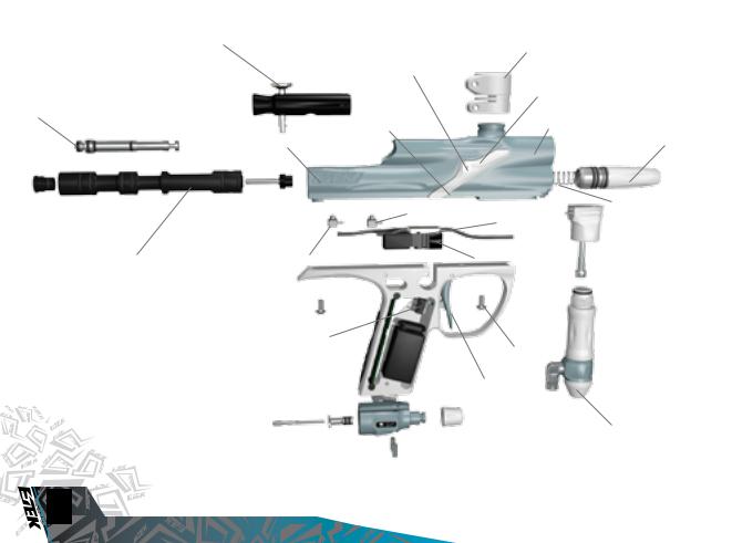
ORIENTATION
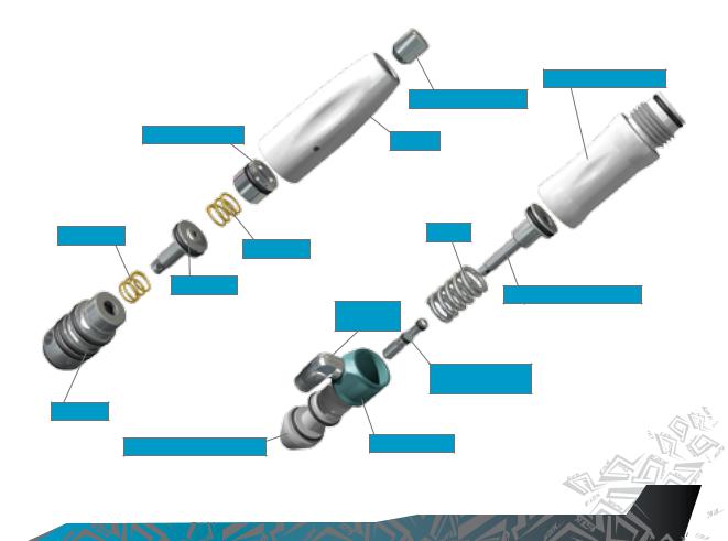
adjuster piston
LPR SPRING
LPR SPRING
LPR PISTON
LPR body
INLINE REGULATOR BOTTOM
INLINE REGULATOR TOP
LPR ADJUSTER SCREW
LPR CAP
Spring
INLINE REGULATOR PISTON
MACROLINE
ELBOW
INLINE REGULATOR
ADJUSTER SCREW
SWIVEL COLLAR
VISIT WWW.PLANETECLIPSE.COM
ORIENTATION 


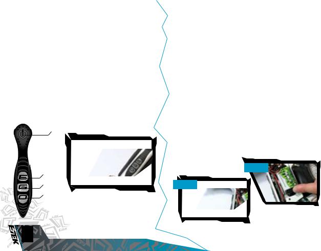
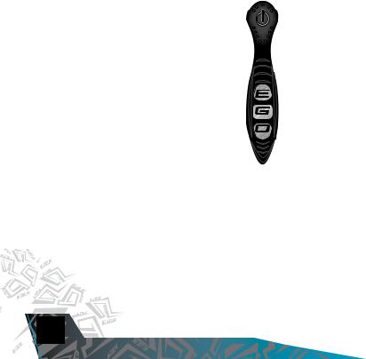
THE Etek2 control CONSOLE
At the rear of the Etek2’s grip frame you will find both the Select push button and three alphabetic LED covers which combine to form the Etek2’s Control Console. The Control Console is used for several different purposes including:
-Turning the Etek2 on and off using the select pushbutton.
-Displaying the value of parameters using the UID.
-Selecting and editing parameters using the select pushbutton.
-Displaying the battery level.
-Turning the Etek BBSS on and off using the select pushbutton.
SELECT BUTTON
TOP LED
MIDDLE LED
BOTTOM LED
ORIENTATION
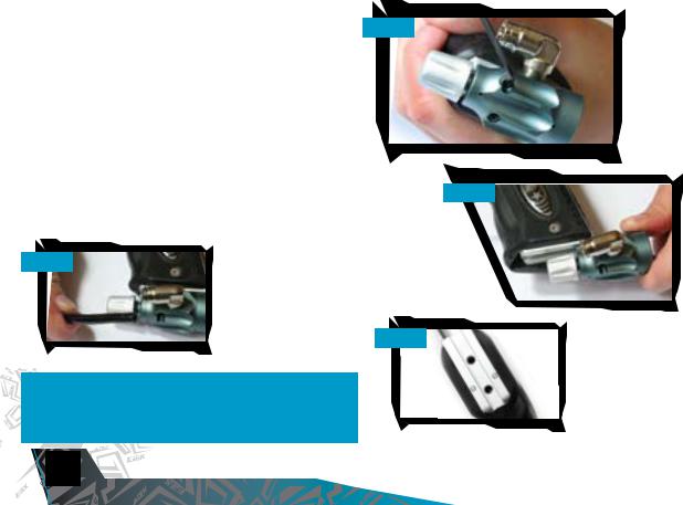
INSTALLING A BATTERY
Ensure that the Etek2 is switched off. Place the marker on a flat surface in front of you with the feed tube furthest away from you and the barrel pointing to the right.
Using a 5/64th” (2mm) hex key, remove the three countersunk screws that holds the rubber grip onto the grip frame. Peel the rubber grip to the right to expose the electronics within the grip frame.
If present remove the existing 9 volt battery by sliding your thumb into the recess provided below the battery and lever the battery gently out of the frame [see figure 2.1].
On top of the battery you will see the battery connector and wire that is used to connect the battery to the circuit board. Gently separate the battery connector from the battery, so that the existing battery can be disposed of accordingly and taking a new 9 volt Alkaline battery (type PP3, 6LR61, MN1064) connect it to the battery connector (See figure 2.2). Note: The battery will only connect to the battery connector one way. If you are unsure of how to install a new battery please contact your nearest Eclipse Service Centre.
Ensure that all of the wires are within the recess of the frame and then replace the rubber grip and tighten the countersunk grip screws using the 5/64th” (2mm) hex key.
FIG 2.1
DO NOT OVER-TIGHTEN THE SCREWS
FIG 2.2
Switching On the Etek2
At the rear of the grip frame is the Control Console. Press and hold the Select Pushbutton [see figure 2.3]. Release the Select Pushbutton when the LED light
up and your Etek2 will begin its power up sequence.
SWITCHINg OFF THE Etek2
Press and hold the Select push button. Release the Select push button when all three of the LEDs on the control console turn red. The LEDs will extinguish one by one and the Etek2 will turn off.
FIRING THE Etek2
If the Break Beam Sensor System is disabled, pull the trigger to the Etek2. If the Break Beam Sensor System is enabled and there is paintball in the breech, pulling the trigger will also fire the Etek2. The entire firing sequence is controlled electronically by the Etek2 circuit board and solenoid, enabling any user to achieve high rates of fire easily.
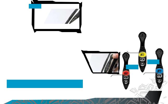
NOTE: WHEN TURNING ON THE Etek2, THE BREAK-BEAM SENSOR SYSTEM IS AUTOMATICALLY ENABLED.
using the break beam sensor system (bbss)
When the Etek2 is powered up, the Break Beam Sensor System (BBSS) is automatically enabled.
To switch off the Break Beam Sensor System, push and hold the Select pushbutton for 0.5 seconds. The “E” on the Control Console will flash red indicating that the Break Beam Sensor System has been disabled [see
figure 2.4].
To switch on the Break Beam Sensor System, push and hold the Select pushbutton for 0.5 seconds. The “E” on the Control Console will flash either yellow (no ball detected) or blue (ball detected) indicating that the Break Beam Sensor System has been enabled [see figure 2.5].
Additional features of the Etek2s Break Beam Sensor System are covered in full in the “Understanding the BBSS Operation” section on Page 14 of this User Manual.
YELLOW LIGHT -
NO BALL DETECTED.
|
FIG 2.5 |
|
FIG 2.4 |
RED LIGHT - |
BLUE LIGHT - |
BALL DETECTED. |
|
BBSS DISABLED. |
|
VISIT WWW.PLANETECLIPSE.COM
QUICK SET-UP 


SETTING UP
Before you can begin to use your Etek2, there are a few necessary components that are required to enable the Etek2 to function; namely an air system and a loader of your choice.
NOTE: the Etek2 cannot be used with co2, it can only be powered by compressed air or nitrogen.
INSTALLING A PRESET
AIR SYSTEM
Every Etek2 comes complete with an Eclipse On/Off Purge System (OOPS) allowing a preset regulator and tank to be screwed straight in for immediate use. Before
screwing the preset into the OOPS ensure that the On/Off knob is wound out approximately half
way [See Figure 3.1].
Be careful not to unscrew the On/Off knob too far as it will come completely out of the OOPS. If this happens, replace the On/Off knob by screwing it
 back into the OOPS body in a clockwise direction.
Screw the preset air system into the OOPS System [See Figure 3.2] so that  the bottle screws in all the way and is tight. Slowly turn the On/Off knob in
  a clockwise direction allowing the On/Off knob System to depress the pin
of the preset air system causing the Etek2 to become pressurized,
providing that there is sufficient air in your tank [See Figure 3.3].
You have now installed a preset air system onto your Etek2.
FIG 3.2
FIG 3.3


 10
10
 USING YOUR ETEK2
T-Slot Mounting System
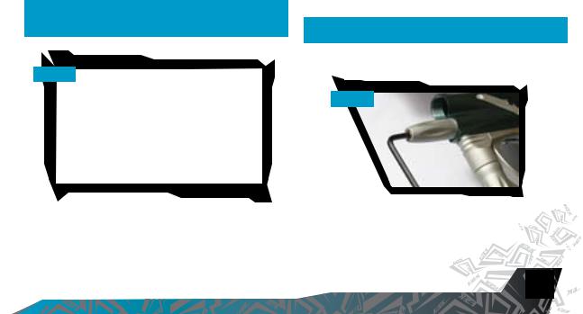
The current industry standard Dovetail rail that is used to connect the ASA to the frame has consistently proved to be the weakest link for every manufacturer out there when it comes to the durability of the system used to mount the tanks to the guns. For that reason we have shunned the flawed design of the dovetail in favour of a new T-Slot design. By using a T-shaped slide rail, as opposed to the double V of the old fashioned dovetail, the ASA-To-Frame interface has been drastically strengthened. There should be no way that a well executed dive into a bunker should dislodge the ASA now, but even if you feel you have to go and use a different ASA there are still standard mounting holes in the frame to fit your own inferior rail and ASA.
T-SLOT MOUNT
Macroline Hosing and Elbows
To aid the longevity of your Macroline hosing, it is very important to remove it from (and install it back into) the fittings in the correct manner:
Pull back the collet section of the Macroline fitting and keep the collet depressed.
Pull the Macroline hose out of the Macroline fitting and release the collet.
Before installing the Macroline hose into the Macroline fitting ensure that the end has been trimmed correctly to ensure a tight fit in the fitting.
Warning: IF YOU EVER REMOVE THE MACROLINE HOSE
FROM THE FITTING, ALWAYS CHECK THE CONDITION OF YOUR MACROLINE HOSING AND IF IT IS WORN OR THE WRONG LENGTH 
 REPLACE IT IMMEDIATELY.


VISIT WWW.PLANETECLIPSE.COM
USING YOUR ETEK2 

 11
11

INSTALLING AN ADJUSTABLE AIR SYSTEM
Firstly disconnect the 1/4” Macroline hosing from the elbow attached to the OOPS at the base of the grip frame (SEE FIGURE 3.4).
Using a 3/32” hex key loosen the two set screws that tighten the OOPS body onto the bottom of the grip frame (see figure 3.5). The OOPS body can now be removed from the T-Slot Rail on the bottom of the grip frame by sliding it backwards (see figure 3.6) to expose the base of the frame.
As well as the integrated slide rail at the base of the Etek2s grip frame, there are also two 10-32 UNF threaded screw holes which will accept standard bottom line screws (SEE FIGURE 3.7).
Attach the air system of your choice, taking care to use the correct fittings and length and size of hose to accommodate your requirments.
FIG 3.4
NOTE: when using an oops on your Etek2, the Etek2 will still  have stored air in the valve chamber, gas line and inline
  regulator after you have turned the oops off. Please
  remember to discharge the stored air in a safe direction as
  you are unscrewing the on/off knob on the oops.
FIG 3.5
.
FIG 3.6
FIG 3.7


 12
12
 USING YOUR ETEK2

attaching a loader
Using a 5/32” hex key, turn the top screw of the feed tube counter clockwise until the feed neck of your loader can easily be pushed into the top of the feed tube (See FIGURE 3.8). Push your choice of loader firmly into the feed tube so that it rests on the shelf inside the feed tube (SEE FIGURE 3.9). Using a 5/32” hex key, tighten the top screw of the feed tube by turning it clockwise until the loader is firmly gripped (SEE FIGURE 3.10).
You have now attached a loader to your Etek2. Once you have filled your loader and air tank you will then be ready to begin using your Etek2.
FIG 3.8
FIG 3.9
FIG 3.10
SWITCHING ON
Pressing and holding the Select pushbutton will switch the Etek2 on. Release the Select pushbutton when the UID lights up and your Etek2 will begin its power up sequence.
VISIT WWW.PLANETECLIPSE.COM
USING YOUR ETEK2 
 13
13

the control console
The Etek2 utilises multi coloured LEDs to display all of the information that the user requires via the Etek2s Control Console.
Each area of the Control Console is used to perform different functions and display different information as outlined below:
The Select Pushbutton is used to:
-Switch the Etek2 On and Off.
-Switch the BBSS (eye system) On and Off.
- To scroll through parameters and edit parameters.
The “E” on the Control Console is used to:
-Display the status of the BBSS (eye system).
-Display the value of a parameter in Tens (10 - 90)
The “G” on the Control Console is used to:
- Display the value of a parameter in Units (0 - 9) - Display the status of the battery.
The “O” on the Control Console is used to:
- Display the value of a parameter in Tenths (0.0 - 0.9)
As a combined unit the “E”, “G” and “O” are also used to:
-Display power up and power down status.
-Display tournament lock status.
-Display that Factory settings have been restored
-To confirm whether a parameter value has been accepted or rejected.


 14
14
 USING YOUR ETEK2
UNDERSTANDING THE BBSS OPERATION
The Etek2 displays the status of the Break Beam Sensor System using the “E” area of the Control Console as follows:
indication |
breech sensor status |
Flashing Yellow |
BBSS enabled (On), no paintball detected |
- marker will not fire. |
|
Flashing Blue |
BBSS enabled (On), paintball detected |
- marker will fire. |
|
Flashing Red |
BBSS disabled (Off) - marker will fire. |
|
|
Double Flashing Red |
Blockage detected, BBSS temporarily |
disabled (Off) - marker will fire. |
Any changes to the Breech Sensor Status will be displayed immediately. This provides valuable feedback to the user.
An example of this is when you are shooting a string of shots with the BBSS enabled, the “E” on the Control Console will alternate in colour from Yellow (no paintball detected) to Blue (paintball detected). In this instance too much yellow would indicate that your chosen loader cannot keep up with how fast you are shooting and is consequently slowing down your rate of fire.
The BBSS is able to switch itself off in the event that a blockage or contamination prevents it from functioning correctly.This is represented by a double flashing red light in the “E” area of the Control Console. The Etek’s ROF will be capped at 10bps. In this instance, the BBSS will switch itself back on once the blockage is cleared and the correct operation of the BBSS can then be resumed.
ADJUSTING YOUR VELOCITY
When using your Etek2, you may wish to change the velocity at which your Etek2 is firing. This is done by inserting a 1/8" hex key into the adjuster screw at the bottom of your Etek2 Inline regulator and adjusting it accordingly (SEE FIGURE 3.11). By turning this adjuster screw clockwise you decrease the output pressure of the inline regulator and consequently the velocity, by turning the adjuster screw counter clockwise you increase the output pressure of the inline regulator and consequently the velocity.
note: After each adjustment fire at least two clearing shots to gain an accurate velocity reading. never exceed 300fps.
ADJUSTING YOUR LPR PRESSURE
When using your Etek2, you may wish to change the output pressure of your LPR. This is easily done by inserting a 5/32" inch hex key into the adjuster screw at the front and adjusting it accordingly (SEE FIGURE 3.12).
By turning the adjuster screw clockwise, you decrease the output pressure of your LPR and consequently reduce the pressure driving your rammer back and forth. By turning the adjuster screw counter clockwise, you increase the output pressure of your LPR and consequently increase the pressure driving your rammer back and forth.
note: turning the adjuster screw out too far will cause it to fall out.
FIG 3.11
FIG 3.12
VISIT WWW.PLANETECLIPSE.COM
USING YOUR ETEK2 
 15
15


SETTING THE TRIGGER
There are three adjustment points on the trigger – the Front Stop Trigger Screw, the Rear Stop Trigger Screw, and the Spring Tension Screw.
FIG 4.2
As standard each Etek2 comes with a factory set trigger travel of approximately 2mm in total length; one millimeter of travel before the firing point and one millimeter of travel after the firing point.
The Front Stop Trigger Screw is used to set the amount of trigger travel prior to the marker firing. Turn this screw clockwise to reduce the amount of travel. Do not turn the screw too far or the trigger will be pushed past the firing point and the marker will not work. Turn this screw counter clockwise to increase the amount of trigger travel [See FigurE 4.1].
The Rear Stop Trigger Screw is used to set the amount of travel after the marker has fired. Turn this screw clockwise to reduce the amount of travel. Do not turn the screw too far or the trigger will be prevented
from reaching its firing point and the marker will not work. Turn this screw FIG 4.3 counter clockwise to increase the amount of travel [See FigurE 4.2).
The Spring Tension Screw is used to adjust the amount of spring tension behind the trigger when it is pulled. Turn the screw clockwise to increase the amount of spring tension. Turn the screw counter clockwise to reduce the amount of spring tension [See FigurE 4.3].
FIG 4.1


 16
16
 ADVANCED SET-UP
 Loading...