


TM
Warning
Warnings for safe Eclipse Ego handling:
• The Eclipse Ego is not a toy.
• Careless or improper use, including failure to follow instructions and warnings within this User Manual and
attached to the Eclipse Ego could cause death or serious injury.
• Do not remove or deface any warnings attached to the Eclipse Ego.
• Paintball Industry standard eye/face/ear and head protection designed specifically to stop paintballs and
meeting ASTM standard F1776 (USA) or CE standard (Europe) must be worn by user and any person
within range.
• Persons under 18 years of age must have adult supervision when using or handling the Eclipse Ego.
• Observe all local and national laws, regulations and guidelines.
• Use only professional paintball fields where codes of safety are strictly enforced.
• Use compressed air/nitrogen only. Do not use Co2.
• Always follow instructions, warnings and guidelines given with any first stage regulator you use with the
Eclipse Ego.
• Use 0.68 calibre paintballs only.
• Keep the Eclipse Ego switched off until ready to shoot.
• Treat every marker as if it is loaded.
• Never point the Eclipse Ego at anything you do not intend to shoot.
• Do not shoot at persons at close range.
WARNING: Adhere striclty to these and all other safety instructions and guidelines.
4
• Always measure your markers velocity before playing paintball, using a suitable chronograph.
• Never shoot at velocities in excess of 300 feet (91.44 meters) per second, or at velocities greater than local
or national laws allow.
• Do not fire the Eclipse Ego without the bolt in the breech, as high-pressure gas will be emitted.
• Do not fire the Eclipse Ego without the bolt pin locked securely in place.
• Never look into the barrel or breech area of the Eclipse Ego whilst the marker is switched on and able to fire.
• Never put your finger or any foreign objects into the paintball feed tube of the Eclipse Ego.
• Never allow pressurised gas to come into contact with any part of your body.
• Always switch off the Eclipse Ego when not in use.
• Always fit a barrel-blocking device to the Eclipse Ego when not in use on the field of play.
• Always remove all paintballs from the Eclipse Ego when not in use on the field of play.
• Always remove the first stage regulator and relieve all residual gas pressure from the Eclipse Ego
before disassembly.
• The Eclipse Ego can hold a small residual charge of gas, typically 2 shots, with the first stage regulator
removed. Always discharge the marker in a safe direction to relieve this residual gas pressure.
• Always remove the first stage regulator and relieve all residual gas pressure from the Eclipse Ego for
transport and storage.
• Always follow guidelines given with your first stage regulator for safe transport and storage.
• Always store the Eclipse Ego in a secure place.
This User Manual Must accompany the product in the event of resale or new ownership. Should you
be unsure at any stage you Must seek expert advice (See Service Centers)
WarningWarning
WarningWarning
Warning
5
IndexIndex
Index
This section provides more detailed information on how
to use and interact with the Eclipse Ego via its user
interface.
• Setting Up
• Installing a Preset Air System
• Installing an Adjustable Air System
• Attaching a loader
• Switching on
• Screen Layout
• The Main Menu
• The Display Menu
• Using the Display Menu
• The Game Timer Menu
• Using the Game Timer Menu
• The Information Menu
• Adjusting Velocity.
• Adjusting the LPR pressure.
This section names the component parts of the Eclipse
Ego marker.
This section provides details on how to get up and
running quickly with your Eclipse Ego. This section is
essential reading for everyone
• Installing a Battery
• Switching On the Eclipse Ego.
• Switching Off the Eclipse Ego.
• Firing the Eclipse Ego.
• Using the Ego Break-Beam Sensor System.
Orientation
Quick Set-Up
Using the Eclipse Ego
6

Display Menu Tree
This section contains more detailed information on
setting up the Eclipse Ego.
• Setting the Trigger
• The Set-Up Menu
• The Mode Menu
• Using the Mode Menu.
• The Timing Menu
• Maximum Rate of Fire (MAX ROF)
• Dwell (DWELL)
• First Shot Drop Off (FSDO)
• The Filter Menu
• Using the Break Beam Breech Sensor System
• Setting the Empty Breech Detection Time (EMPTY)
• Setting the Ball Detection Time (BALL)
• Using the Trigger Filtering
• Setting the Trigger Pull Time (PULL)
• Setting the Trigger Release Time (RELEASE)
• Using the Trigger Transition Filtering
• Setting the Trigger Transition Band (TT BAND)
• Setting the Trigger Transition Tolerance (TT TOL)
• The Factory Settings Menu
• Using the Factory Settings Menu.
This section provides a quick reference to the User
Interface.
This section acts as a guide to performing routine
maintenance.
• Cleaning the Break Beam Sensor System.
• Stripping and Cleaning the Inline Regulator.
• Stripping and Cleaning the LPR.
• Cleaning and Lubricating the Rammer.
• How to fully strip down the Eclipse Ego (including
Exhaust Valve replacement).
• Assembling the Eclipse Ego.
• Cleaning and Lubricating the bolt.
This section provides information on how to resolve any
problems that might arise with your Eclipse Ego.
Maintenance
Fault Finding
Advanced Set-Up
IndexIndex
Index
Index
Index
7
IndexIndex
Index
This section provides an explanation of the terminology
used in the Eclipse Ego manual.
Tear-out product registration card to be completed and
returned to Planet Eclipse. Alternatively register online
at www.planeteclipse.com.
Available upgrade / repair kits for your Eclipse Ego
Marker.
This section provides information on the location of your
nearest Eclipse Ego Service Centre.
This section provides space for you to record your
favourite Eclipse Ego settings.
This section provides a table of the Eclipse Ego Electropneumatic marker components with their corresponding
order codes.
Setting Savers
Service Centres
Glossary
Warranty Card
Parts List
Spares & Repairs
8
Please complete the details to keep a permanent record
of your purchase of an Eclipse Ego. Please note, the
form is intended for your personal records only, and will
not act as a suitable warranty card for your purchase.
Please complete the warranty card provided in the
manual or the online warranty form, which can be found
at www.planeteclipse.com to validate your Eclipse
warranty.
Product Purchased Colour
• This Users Manual is in English.
• It contains important safety guidelines and Instructions.
• Should you be unsure at any stage, or unable to understand the contents within this manual you must seek
expert advice.
• Le mode d'emploi est en Anglais.
• Ilcontient des instructions et mesures de sécurité importantes.
• En cas de doute, ou s'il vous est impossible de comprendre le contenu du monde d'emploi, demandez conseil à
un expert.
• Este manual de (operarios y) usarios està en Inglés.
• Contiene importantes normas de seguridad e instrucciones.
• Si no esta seguro de algùn punto o no entiende los conteindos de este manual debe conultar con un experto.
• Diese Bedienungs - und Benutzeranleitung ist in Englisch.
• Sie enthålt wichtige Sicherheitsrichtlinen und - bestimmungen.
• Solten Sie sich in irgendeiner Weise un sicher sein. Oder den inhalte dies heftes nicht versthen, lassen Sie siche
bitte von einen Experten beraten.
For Your Records
Date of Purchase Purchased From
Purchase Price Serial Number
IndexIndex
Index
Index
Index
9

OrientationOrientation
Orientation
FRM
FRM Screw
LPR Cap
LPR Adjuster Screw
Ego Body
Clamping Feed
Ego Bolt
Ego Bolt Pin
Rammer Cap
Rammer (Inside Housing)
Sensor Cover
Sensor Cover Screw
Break Beam Sensor System
OOPS
OOPS Slide Rail
Eclipse Inline Regulator
Battery
Ego Trigger
PCB
Ego Grip Frame
Frame Tag
Frame Screw
Rear QEV
Front QEV
Minifold
Solenoid
Rammer Housing
Exhaust Valve
Exhaust Valve Spring
Frame Screw
Valve Plug
LPR Body
10
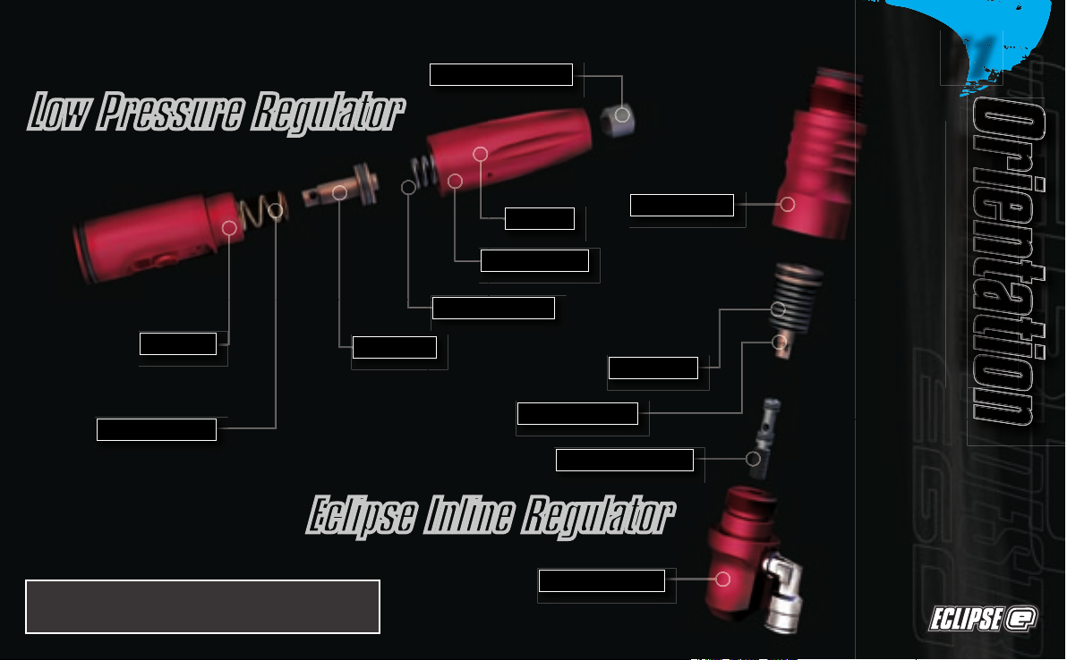
NOTE: for a more detailed explanation of
parts please see the Glossary section.
Low Pressure Regulator
Eclipse Inline Regulator
Rear LPR Spring
LPR Body
LPR Piston
Front LPR Spring
Adjuster Piston
LPR Cap
LPR Adjuster Screw
Inline Reg Top
Spring Pack
Inline Reg Piston
Reg Adjuster Screw
Inline Reg Bottom
OrientationOrientation
OrientationOrientation
Orientation
11
OrientationOrientation
Orientation
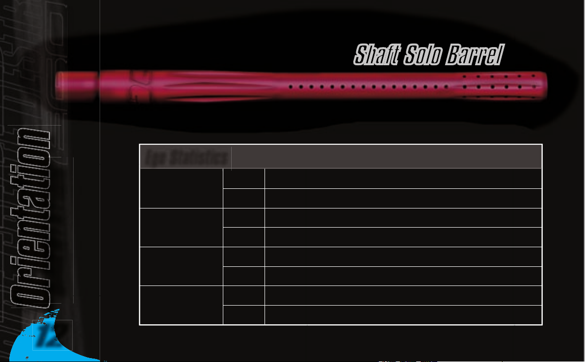
Weight 859g Eclipse Ego and Eclipse Inline Regulator.
1116g
Eclipse Ego and Eclipse Inline Regulator with Shaft Solo Barrel and Oops.
255mm Eclipse Ego.Length
162mm Eclipse Ego Body and Frame.
524mm Eclipse Ego with Shaft Solo Barrel.
Height
Width
25.3mm Eclipse Ego.
232mm Eclipse Ego Body and Frame with Oops.
27.3mm Eclipse Ego with Eye Covers.
Shaft Solo Barrel
Ego Statistics
12

Installing a Battery
Ensure that the Eclipse Ego is switched off. Lay the
marker on a flat surface in front of you, with the feed
tube furthest away and with the barrel pointing to the
right.
Use a 5/64” hex wrench to remove the three
countersunk screws that hold the rubber grip onto the
frame (Note: a 2mm hex key can also be used). Peel
the grip to the right to expose the electronics within the
frame.
If present, remove the existing battery by sliding your
thumb into the recess below the battery and levering
the battery out of the frame
(See Figure 2.1)
.
Do Not pull on the top of the battery to remove it as this
can cause the battery terminals to bend and will result
in a poor electrical connection.
Fit a 9-volt alkaline battery (type PP3, 6LR61 or
MN1604) into the recess with the battery terminals
away from you. The positive terminal should be on the
right hand side, nearest to the side of the frame
(See Figure 2.2).
Ensure that all of the wires are within the recess of
the frame then replace the rubber grip and replace the
three countersunk screws. Do Not over-tighten the
screws.
FIGURE 2.2
FIGURE 2.1
Quick Set-UpQuick Set-Up
Quick Set-Up
Quick Set-Up
Quick Set-Up
13
Quick Set-UpQuick Set-Up
Quick Set-Up
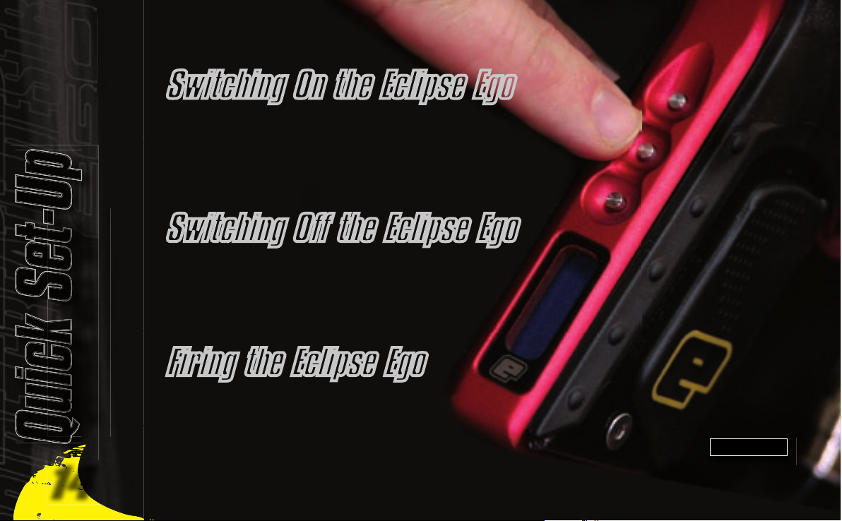
At the rear of the frame, are three recessed
pushbuttons. Press and hold the centre pushbutton
(See Figure 2.3)
. After one second the Eclipse Ego logo
will be displayed. Release the pushbutton and the
display will revert to the designated run screen (Rate of
Fire, Shot Counter or Game Timer).
Press and hold the centre pushbutton for 1 second. The
display will read
OFF
. Release the centre pushbutton and
re-press it to turn off the Eclipse Ego. Alternatively when
the display reads
OFF
, you can also pull the trigger once
to turn off the Eclipse Ego.
Pull the trigger to fire the Eclipse Ego. The entire firing
sequence is controlled electronically by the Eclipse Ego
circuit board and solenoid, enabling any user to achieve
high rates of fire easily.
Switching On the Eclipse Ego
Switching Off the Eclipse Ego
Firing the Eclipse Ego
FIGURE 2.3
14
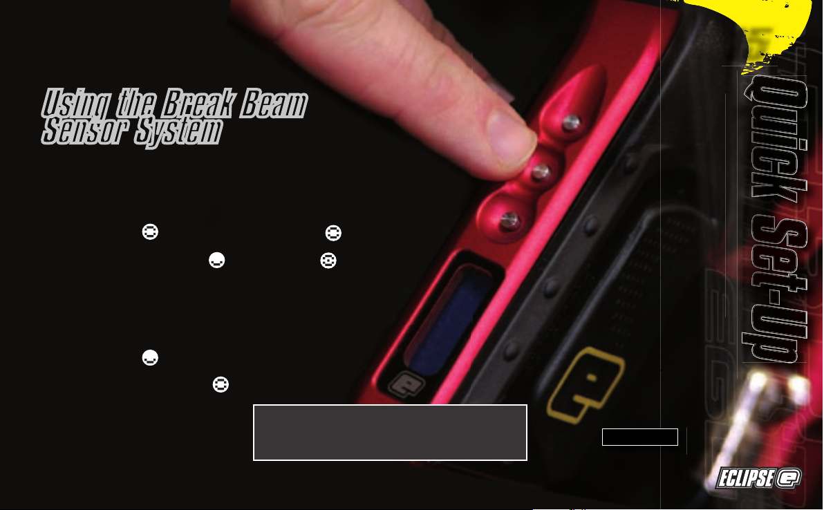
Using the Break Beam
Sensor System
To switch off the Break Beam
Sensor System, press and hold the
top pushbutton for one second
(See Figure 2.4).
The eye on icon in the top left
hand corner of the LCD screen
will change to the eye off icon
indicating that the breech sensor
has been disabled.
To switch the Break Beam Sensor
System back on, press and hold the
top pushbutton for one second.
The eye off icon in the top left
hand corner of the LCD screen
will change to the eye on icon
indicating that the breech sensor
has been enabled.
When the Break Beam Sensor
System is enabled, the icon will
change depending on if the system
has detected a ball or not. When
no ball has been detected the icon
looks like this when a ball has
been detected the icon changes to
look like this.
FIGURE 2.4
Note: when turning on the Eclipse Ego, the
Break Beam Sensor System is automatically
enabled.
Quick Set-UpQuick Set-Up
Quick Set-Up
Quick Set-Up
Quick Set-Up
15

Using The EgoUsing The Ego
Using The Ego
Before you can begin to use your Eclipse Ego, there are a few necessary
components that are required to enable the Eclipse Ego to function; namely
an air system and a loader of your choice.
Every Eclipse Ego comes complete with an Eclipse On/Off Purge System
(OOPS) allowing a preset regulator and tank to be screwed straight in for
immediate use. Before screwing the preset system into the OOPS ensure
that the on/off knob is wound out approximately half way
(See Figure 3.1)
. Be
careful not to unscrew the on/off knob too far as it will come completely out
of the OOPS. If this happens, replace the on/off knob by screwing it back
into the OOPS in a clockwise direction.
Screw the preset air system into the OOPS
(See Figure 3.2)
so that the bottle
screws in all the way and is tight. Slowly turn the on/off knob in a clockwise
direction allowing the OOPS to depress the pin of the preset air system,
causing the Eclipse Ego to become pressurised, providing there is sufficient
air in your tank
(See Figure 3.3)
. You have now installed a preset air system
to your Eclipse Ego.
FIGURE 3.1
FIGURE 3.2
FIGURE 3.3
Installing a Preset Air System
Setting Up
Note: When utilising an OOPS on your Eclipse Ego, the Eclipse
Ego will store air in the valve chamber after the OOPS has dumped
the supply in your gas line and inline regulator. Please remember to
discharge the stored air in a safe direction as you are unscrewing the
on/off knob on the OOPS.
Note: The Eclipse Ego cannot be used with Co2, it can only be
powered by Compressed Air or Nitrogen.
16
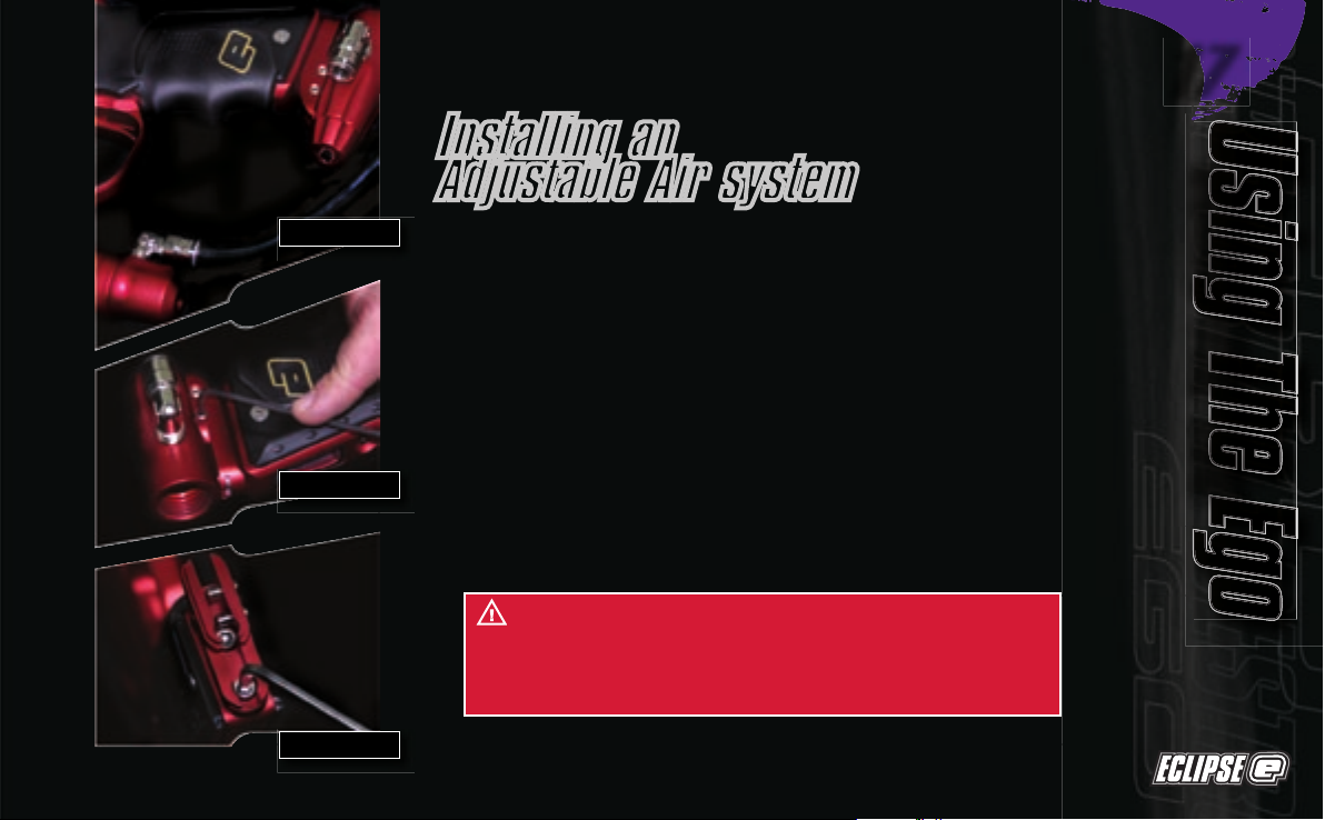
Installing an
Adjustable Air system
Firstly disconnect the 1/4” hosing from the elbow attached to the OOPS
at the base of the frame
(See Figure 3.4)
. Unscrew the on/off knob from the
OOPS, and using a 3/32” Hex key turn the two screws on the left hand side
of the OOPS rail counter clockwise so that the body of the OOPS can be
removed by sliding it out
(See Figure 3.5)
. Using a 5/32” hex key remove the
two screws that attach the OOPS rail to the bottom of the Eclipse Ego grip
frame and remove the OOPS rail
(See Figure 3.6)
.
Attach the air system of your choice, taking care to ensure that you use
the correct length and size of hosing and elbows to accommodate your
requirements.
WARNING: Before attaching any fixed air system, place
attaching screw in designated slide rail and measure protruding
screw length. Screw length must not protrude more than 10mm/
0.40" otherwise the Ego Printed Circuit Board will become
damaged.
FIGURE 3.4
FIGURE 3.5
FIGURE 3.6
Using The EgoUsing The Ego
Using The EgoUsing The Ego
Using The Ego
17
Using The EgoUsing The Ego
Using The Ego
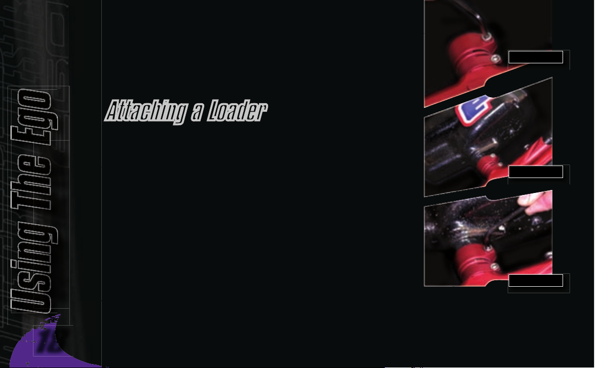
Using a 5/32” hex key, turn the top screw of the clamping feed tube counter
clockwise until the feed neck of your loader can easily be pushed into the
top of the clamping feed tube
(See Figure 3.7)
. Push your choice of loader
firmly into the clamping feed tube so that it rests on the shelf inside the
clamping feed tube
(See Figure 3.8)
. Using a 5/32” hex key, tighten the top
screw of the clamping feed tube by turning it clockwise until the loader is
firmly gripped
(See Figure 3.9)
.
You have now attached a loader to your Eclipse Ego. Once you have filled
your loader and air tank you will then be ready to begin using your Eclipse
Ego.
Attaching a Loader
FIGURE 3.9
FIGURE 3.8
FIGURE 3.7
18
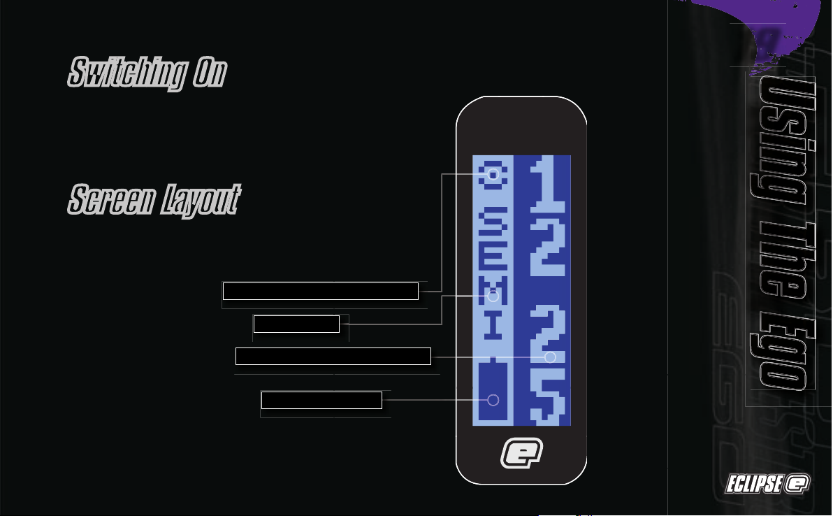
Pressing and holding the
Select
(middle) pushbutton will
switch the Eclipse Ego on. The LCD display will show
the Eclipse Ego logo. When the pushbutton is released,
the LCD display will show the designated display
screen.
The standard layout of an Eclipse Ego display is
as follows:
Switching On
Screen Layout
Mode Selection
Battery Level Indicator
Break Beam Sensor System Indicator
Dependant on Display Screen Choice
Using The EgoUsing The Ego
Using The EgoUsing The Ego
Using The Ego
19
Using The EgoUsing The Ego
Using The Ego
Press the
Lower
(bottom) pushbutton to scroll down through each of the
options on the menu. Once the last option on the menu has been displayed,
pressing the
Lower
pushbutton will cause the first option to be displayed.
Press the
Raise
(top) pushbutton to scroll up through each of the options on
the menu. Once the first option on the menu has been displayed, pressing
the
Raise
pushbutton will cause the last option to be displayed.
Press the
Select
pushbutton to select the displayed option.
Selecting the
BACK
option will return the display to the display from which the
Main Menu was selected.
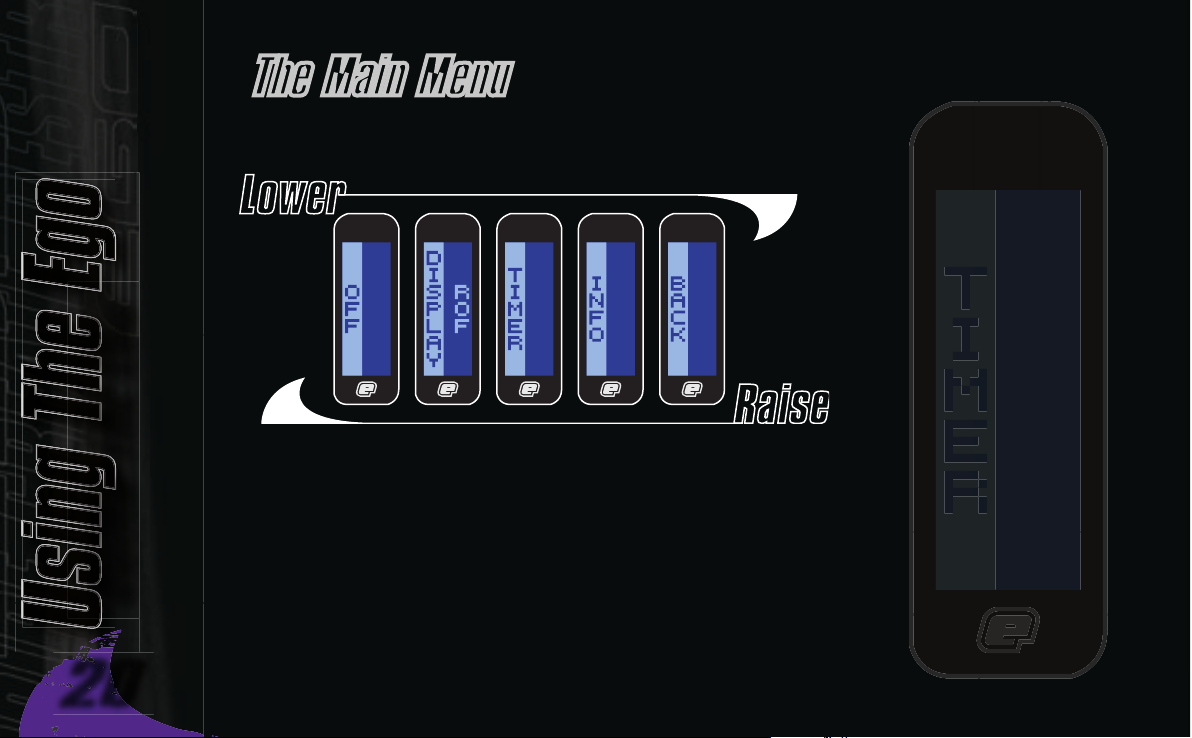
The Main Menu
To activate the Main Menu (providing the Eclipse Ego is already turned on),
press and hold the
Select
pushbutton. After one second
OFF
will be displayed.
This is one of the options on the Main Menu, as shown below:
20
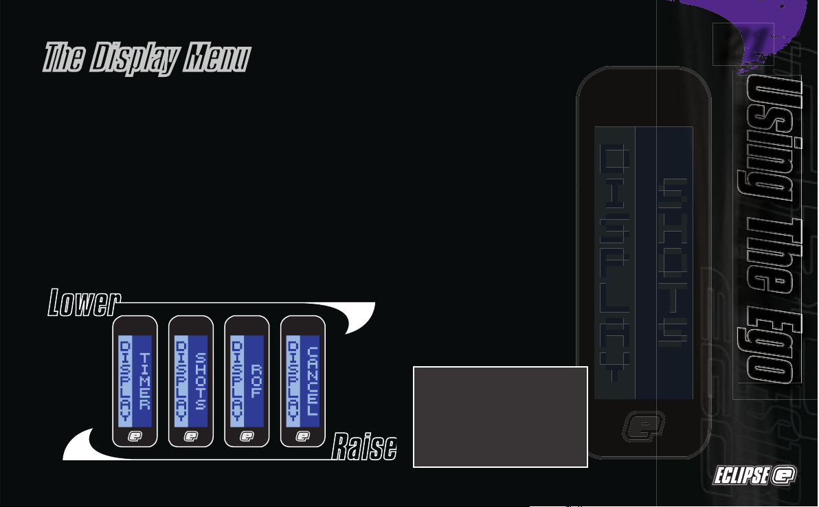
To display the Game Timer when the frame is in
normal use, simply
Select
the
TIMER
option from the
DISPLAY
Menu.
To display the Shot Counter when the frame is in
normal use, simply
Select
the
SHOTS
option from the
DISPLAY
Menu.
To display the Rate of Fire Indicator when the frame
is in normal use, simply
Select
the
ROF
option from
the
DISPLAY
menu.
To return to the Main Menu, scroll to
the
CANCEL
option and press
Select
.
The Display Menu
Scroll through the main menu until the
DISPLAY
option is displayed and then press
Select.
This has
now activated the
DISPLAY
Menu.
The left hand side of the screen shows
DISPLAY
, the
name of the option that you are currently in, whilst
the right hand side of the screen can be changed
by using the
Raise
and
Lower
pushbuttons to scroll
through the different
DISPLAY
options as detailed
below:
NOTE: The option chosen in
the
DISPLAY
menu will be
the designated run screen
when the Eclipse Ego is in
normal use, and when the
marker is first switched on.
Using The EgoUsing The Ego
Using The EgoUsing The Ego
Using The Ego
21

Using The EgoUsing The Ego
Using The Ego
As both the
TIMER
and the
SHOTS
options from the
DISPLAY
Menu are covered in their respective sections in the
following pages we will start by looking at the Rate of
Fire option.
The Rate of Fire
(ROF)
option is a means by which you
can monitor your rate of fire whilst using the Eclipse
Ego. The Rate of Fire screen looks like the screen to
the left.
With the Break Beam Sensor System enabled and
paint present, the rate of fire is only limited to the speed
of your loader. To achieve the highest rates of fire we
recommend using a high-speed loader such as the
HALO, Evolution 2 or Q-loader. With the Break Beam
Sensor System enabled, and no paint present, the rate
of fire will be 0, as your Eclipse Ego will not be able to
fire.
To use the Rate of Fire screen without shooting paint,
simply switch the Break Beam Sensor System off using
the
Raise
pushbutton. In this scenario, the Rate of Fire is
only limited to whatever value you have selected in the
MAX ROF
option in the
TIMING
Menu.
The Rate of Fire Indicator records every pull and
release of the trigger over a period of one second and
calculates the number of valid shots that were fired
during that period.
The current Rate of Fire is displayed in the top right
hand corner. The maximum Rate of Fire that has been
achieved is displayed in the bottom right hand corner.
To reset the maximum Rate of Fire simply push and
hold the
Lower
pushbutton for a 1 second period.
Using the Display Menu Rate of Fire Option
Battery Level Indicator
Maximum Rate of Fire Achieved
Current Rate of Fire
Break Beam Sensor System Indicator
22

To set the game timer, simply
Select
the
GAME
option.
To set the alarm timer, simply
Select
the
ALARM
option.
To set the starting method of the game timer, simply
Select
the
START
option.
To return to the Main Menu, scroll to the
BACK
option
and press
Select
.
Scroll through the Main Menu until the
TIMER
option is
displayed and then press Select. You have now entered
the
GAME TIMER
Menu.
By using the
Raise
and
Lower
pushbuttons, you can scroll
through the menu as illustrated below:
Once the
GAME
option has been selected from the
GAME TIMER
Menu, the preset game time will be
displayed on the right hand side of the screen, the
factory setting for which is 7 minutes and 10 seconds.
You will also notice that the Edit Indicators appear on
the display, indicating that you are editing that particular
feature, as shown on the right.
To increase the preset game time, repeatedly press
and release the
Raise
pushbutton. Each time that the
pushbutton is pressed, the game time will increase by
10 seconds. To increase the time more rapidly, press
and hold the
Raise
pushbutton. The maximum preset
game time is 60 minutes and 0 seconds, once this
value has been exceeded the game timer will wrap
around to 0 minutes and 0 seconds.
To decrease the preset game time, repeatedly press
and release the
Lower
pushbutton. Each time that the
pushbutton is pressed, the game time will decrease by
10 seconds. To decrease the time more rapidly, press
and hold the
Lower
pushbutton. The minimum preset
game time is 0 minutes and 0 seconds, once this value
has been exceeded the game timer will wrap around to
60 minutes and 0 seconds.
Once you have set the game timer to the preset time
that you require, press the
Select
pushbutton to save the
value. The Edit Indicators will disappear, indicating that
the time has been accepted.
The Game Timer Menu
Setting the Game Timer
Edit Indicators
Using The EgoUsing The Ego
Using The EgoUsing The Ego
Using The Ego
23

Using The EgoUsing The Ego
Using The Ego
Setting the Alarm Time
As well as a game timer we have
an added
Alarm
feature that allows
you to set a designated time during
the game timer at which the
Alarm
feature will be activated. When the
game timer reaches the Alarm time
the display will flash repeatedly for
5 seconds to indicate this.
Once the
ALARM
option has been
selected from the
GAME TIMER
Menu,
the edit indicators will appear
and the preset alarm time will be
displayed on the right hand side of
the screen, the factory setting for
which is 1 minute and 0 seconds.
To increase the preset alarm time,
repeatedly press and release
the
Raise
pushbutton. Each time
that the pushbutton is pressed,
the alarm time will increase by 1
second. To increase the time more
rapidly, press and hold the
Raise
pushbutton. The maximum preset
alarm time is 60 minutes and 0
seconds, once this value has been
exceeded the alarm timer will wrap
around to 0 minutes and 0 seconds.
To decrease the preset alarm time,
repeatedly press and release the
Lower
pushbutton. Each time that
the pushbutton is pressed,
the alarm time will decrease by
1 second. To decrease the time
more rapidly, press and hold the
Lower
pushbutton. The minimum
preset alarm time is 0 minutes and
0 seconds, once this value has
been exceeded the alarm timer will
wrap around to 60 minutes and 0
seconds.
Once you have set the alarm time
to the preset time that you require,
press the
Select
pushbutton to save
the value. The edit indicators will
disappear, indicating that the time
has been accepted.
24

Once the
START
option has been selected from the
GAME TIMER
Menu, the edit indicators will appear and
the preset method of starting the Game Timer will be
displayed on the right hand side of the screen, the
factory setting for which is
BUTTON
.
To change the starting option for the Game Timer,
simply use the
Raise
or
Lower
pushbuttons to scroll
through the menu choices:
(See Figure 3.10)
BUTTON
means that pressing the
Lower
pushbutton will
start the game timer (when displayed).
When
TIMER
has been selected as the designated
Display screen, the Game Timer will be displayed.
Starting the Game Timer depends on whether you have
chosen
BUTTON
or
TRIGGER
in the
START
option of the
GAME
TIMER
Menu (detailed on the left). By starting the
Game Timer using your chosen method, the timer will
start to count backwards, in seconds, towards zero.
To stop the Game Timer, push and release the
Lower
pushbutton. The Game Timer will pause at whatever
time it had counted down to.
To now reset the Game Timer, press and hold the
Lower
pushbutton for 1 second. The Game Timer will return
to its preset value. The Game Timer will also be reset
whenever the Eclipse Ego is switched off.
Setting the Start
Method of the Game Timer
Starting the Game Timer
FIGURE 3.10
TRIGGER
means that pulling the trigger will start the game
timer (when displayed).
Selecting
CANCEL
returns to the
GAME TIMER
Menu.
Using The EgoUsing The Ego
Using The EgoUsing The Ego
Using The Ego
25

Using The EgoUsing The Ego
Using The Ego
The Information Menu
In the
INFO
Menu, the Eclipse Ego displays the current
version of firmware that it has programmed into it,
and the total number of shots that the frame has fired.
There is no user interaction in the
INFORMATION
Menu, it
is simply a way of finding out facts about your Eclipse
Ego.
To display the current Version of Firmware being used,
scroll to the VERSION option.
To display the Total number of shots that your Ego has
fired, scroll to the
T SHOTS
option.
To return to the Main Menu, scroll to the
BACK
option
and press
Select
.
Scroll through the Main Menu until the
INFO
option is
displayed and then press
Select
. You have now entered
the
INFORMATION
Menu .
By using the
Raise
and
Lower
pushbuttons, you can
scroll through the
INFO
Menu as illustrated below:
26

When using your Eclipse Ego, you may wish to change the velocity at
which your Eclipse Ego is firing. This is done by inserting a 1/8th" hex key
into the adjuster screw at the bottom of your Eclipse Ego Inline regulator
and adjusting it accordingly
(See Figure 3.10)
. By turning this adjuster screw
clockwise you decrease the output pressure of the inline regulator and
consequently the velocity, by turning the adjuster screw counter clockwise
you increase the output pressure of the inline regulator and consequently
the velocity.
When using your Eclipse Ego, you may wish to change the output pressure
of your LPR. This is easily done by inserting a 5/32nd" inch hex key into the
adjuster screw at the front and adjusting it accordingly
(See Figure 3.11)
. By
turning the adjuster screw clockwise, you decrease the output pressure of
your LPR and consequently reduce the pressure driving your hammer back
and forth. By turning the adjuster screw counter clockwise, you increase the
output pressure of your LPR and
consequently increase the pressure driving
your hammer back and forth.
FIGURE 3.10
FIGURE 3.11
Adjusting Your Velocity
Adjusting your LPR Pressure
Note:
turning the adjuster screw out too far will cause it to fall out.
Note:
after each adjustment fire two clearing shots to
gain an accurate velocity reading. Never exceed 300fps.
Using The EgoUsing The Ego
Using The EgoUsing The Ego
Using The Ego
27

Advanced Set-UpAdvanced Set-Up
Advanced Set-Up
Setting The Trigger
There are three adjustment points on the trigger - the
Front Stop Trigger
Screw
, the
Rear Stop Trigger Screw
and the
Return Strength Trigger Screw
.
As standard each Eclipse Ego comes with a factory-set trigger travel of
approximately 2mm in total length: one millimetre of travel before the
firing point, and one millimetre of travel after the firing point.
The
Front Stop Trigger Screw
is used to set the amount of trigger travel
prior to the marker firing. Turn this screw clockwise to reduce the
amount of travel. Do not turn the screw too far or the trigger will be
pushed past its firing point and the marker will not work. Turn this screw
counter clockwise to increase the amount of trigger travel
(See Figure 4.1)
The
Rear Stop Trigger Screw
is used to set the amount of trigger travel
after the marker has fired. Turn this screw clockwise to reduce the
amount of travel. Do not turn the screw too far or the trigger will be
prevented from reaching its firing point and the marker will not work.
Turn this screw counter clockwise to increase the amount of trigger
travel
(See Figure 4.2)
The
Return Strength Trigger Screw
is used to adjust the amount of force
with which the trigger is returned to its rest position. Turn the screw
clockwise to increase the amount of force
(See Figure 4.3)
. Do not turn
the screw too far or it will negate the position of the Front Stop Trigger
Screw. Turn the screw counter clockwise to reduce the amount of force.
Do not turn the screw too far or there will not be enough force to return
the trigger.
Once you have set the trigger to your preference, refer to setting the
TT
BAND (see page 37)
, as it is very important that the
TT BAND
and trigger pull
are set up together for the Trigger Transition Filtering to work correctly.
FIGURE 4.1
FIGURE 4.2
FIGURE 4.3
28

To activate the
SET-UP
Menu, first remove the three rubber grip screws from
the right hand side of the frame
(See Figure 4.4)
and peel back the rubber
grip to expose the PCB inside the frame. Press and hold the
Set-up
pushbutton, which is located on the PCB above the battery
(See Figure 4.5)
.
After one second, the
MODE
parameter will be displayed - this is the first item
on the
SET-UP
Menu
(See Figure 4.6)
Press the
Lower
pushbutton to scroll down through each of the items on
the menu. Once the last item has been displayed, pressing the
Lower
pushbutton will cause the first item to be displayed.
Press the
Raise
pushbutton to scroll up through each of the items on the
menu. Once the first item has been displayed, pressing the
Raise
pushbutton
will cause the last item to be displayed.
Press the
Select
pushbutton to select the displayed item.
Selecting
BACK
will return the display to the display from which the
SET-UP
Menu was selected.
The Set Up Menu
FIGURE 4.5
FIGURE 4.4
FIGURE 4.6
Advanced Set-UpAdvanced Set-Up
Advanced Set-Up
Advanced Set-Up
Advanced Set-Up
29

Advanced Set-UpAdvanced Set-Up
Advanced Set-Up
The Mode Parameter
The
Mode
Parameter is used to control the firing mode
of the Ego. Please Note: Certain modes may only be
available in certain countries and on certain models of
Eclipse Ego.
Scroll through the
Set-up
menu until the
Mode
parameter
is displayed. The current firing mode is shown on the
right-hand side of the display. To change the
Mode
parameter press
Select
and the edit indicators will
appear
(See Figure 4.8)
Press the
Lower
pushbutton to scroll down through
each of the available firing mode options. Once the
last option has been displayed, pressing the
Lower
pushbutton will cause the first option to be displayed.
Press the
Raise
pushbutton to scroll up through each of
the available firing mode options. Once the first option
has been displayed, pressing the
Raise
pushbutton will
cause the last option to be displayed.
Press the
Select
pushbutton to change the firing mode
to the displayed option.
Selecting
BACK
will return the display to the
Set-up
Menu.
Press the
Lower
pushbutton to scroll down through each of the items on
the
TIMING
Menu. Once the last item has been displayed, pressing the
Lower
pushbutton will cause the first item to be displayed.
Press the
Raise
pushbutton to scroll up through each of the items on the
TIMING
Menu. Once the first item has been displayed, pressing the
Raise
pushbutton will cause the last item to be displayed.
Press the
Select
pushbutton to edit the displayed parameter.
Selecting
BACK
will return the display to the
Set-up
Menu.
The
TIMING
Menu provides access to parameters which control the Ego's
firing cycle.
Scroll through the
Set-up
Menu until
TIMING
is displayed and then press
Select
. This will display
MAX ROF
the first item on the
TIMING
Menu
(See Figure 4.7)
FIGURE 4.7
The Timing Menu
30

Maximum Rate of Fire
The
MAX ROF
parameter is used to control how
fast the Ego cycles when the Break Beam Sensor
System is disabled. This parameter should be set
to match the slowest speed of the loading system
in use.
Scroll through the
Timing
Menu until the
MAX ROF
parameter is displayed.
The current value of the
Maximum Rate of Fire
is
shown in balls per second on the right hand side of
the display. Press the
Select
pushbutton to enter the
edit function
(See Figure 4.8)
Press and release the
Raise
pushbutton to increase
the
MAX ROF
value in 1 ball per second increments.
Up to a maximum of 30 bps. Press and hold the
Raise
pushbutton to increase the
MAX ROF
value more
rapidly.
Press and release the
Lower
pushbutton to decrease
the
MAX ROF
value in 1 ball per second increments.
Down to a minimum of 1 bps.Press and hold the
Lower
pushbutton to decrease the
MAX ROF
value
more rapidly.
Press
Select
to save the
MAX ROF
value and the edit
indicators will disappear from the display to indicate
that the value has been accepted. You have now
returned to the
Timing
Menu.
Dwell
The Dwell parameter controls the amount of time
that the solenoid is energised and therefore the
amount of gas that is released with each shot.
Scroll through the
Timing
Menu until the
DWELL
parameter is displayed.
The current value of the
DWELL
is shown on the right
hand side of the display
(See Figure 4.9)
Press the
Select
pushbutton to enter the edit
function and the edit
indicators will appear on the
display.
Press and release the
Raise
pushbutton to increase
the
DWELL
time in 0.1 millisecond increments. Press
and hold the
Raise
pushbutton to increase the
DWELL
time more rapidly.
Press and release the
Lower
pushbutton to decrease
the
DWELL
time in 0.1 millisecond increments. Press
and hold the
Lower
pushbutton to decrease the
DWELL
time more rapidly.
Press
Select
to save the
DWELL
time and the edit
indicators will disappear from the display to indicate
that the value has been accepted. You have now
returned to the
Timing
Menu.
FIGURE 4.8
FIGURE 4.9
Edit Indicators
Advanced Set-UpAdvanced Set-Up
Advanced Set-Up
Advanced Set-Up
Advanced Set-Up
31

Advanced Set-UpAdvanced Set-Up
Advanced Set-Up
First Shot Drop Off
First shot drop off is a reduction in velocity of
the first paintball to be fired after the Ego has
been left un-fired for any length of time. The
FSDO
parameter is used to define an increase
in dwell time for the 'First Shot' in order to
combat this problem.
Scroll through the
Timing
Menu until the
FSDO
parameter is displayed.
The current value of the
First Shot Drop Off
is
shown on the right hand side of the display
(See Figure 4.10)
Press the
Select
pushbutton to
enter the edit
function and the edit indicators will appear on
the display.
Press and release the
Raise
pushbutton to
increase the
FSDO
value in 0.1ms increments.
Press and hold the
Raise
pushbutton to
increase the
FSDO
value more rapidly.
Press and release the
Lower
pushbutton to
decrease the
FSDO
value in 0.1ms increments.
Press and hold the
Lower
pushbutton to
decrease the
FSDO
value more rapidly.
Press
Select
to save the
FSDO
value
and the
edit indicators will disappear from the display to
indicate that the value has been accepted.
You have now returned to the
Timing
Menu.
The
FILTER
Menu provides access to parameters that are used
to control the various software filters.
Scroll through the
Set-up
Menu until the
FILTER
is displayed
and then press Select. This will display
EMPTY
, the first item
on the
Filter
Menu
(See Figure 4.11)
Press the
Lower
pushbutton to scroll down through each of
the items on the
Filter
Menu. Once the last item has been
displayed, pressing the
Lower
pushbutton will cause the first
item to be displayed.
Press the
Raise
pushbutton to scroll up through each of
the items on the
Filter
Menu. Once the first item has been
displayed, pressing the
Raise
pushbutton will cause the last
item to be displayed.
Press the
Select
pushbutton to edit the displayed parameter.
Selecting
BACK
will return the display to the
SET-UP
Menu.
FIGURE 4.10
FIGURE 4.11
The Filter Menu
32

Setting the Empty Breech Detection Time
Custom and third party bolts can fool the BBSS if they
have slots or holes that allow the Break Beam to pass
through. To overcome this problem the
EMPTY
parameter
defines how long the Break Beam has to be in-tact
before the breech is considered to be empty.
Scroll through the
Filter
Menu until the
EMPTY
parameter
is displayed.
The current value of the
Empty Breech Detection Time
(EMPTY)
is shown on the right hand side of the display
(See Figure 4.12)
Press the
Select
pushbutton to enter the edit function
and the edit indicators will appear on the display.
Press and release the
Raise
pushbutton to increase the
EMPTY
value in 1 millisecond increments. Press and hold
the
Raise
pushbutton to increase the
EMPTY
value more
rapidly.
Press and release the
Lower
pushbutton to decrease the
EMPTY
value in 1 millisecond increments. Press and hold
the
Lower
pushbutton to decrease the
EMPTY
value more
rapidly.
Press
Select
to save the
EMPTY
value and the edit
indicators will disappear from the display to indicate that
the value has been accepted. You have now returned to
the
Filter
Menu.
Using the Break Beam Sensor System
During the firing cycle, the breech sensor looks first for an
empty breech and then for a paintball within the breech. Only
when the sensor has detected both conditions will it allow the
Eclipse Ego to be fired. The sensor software
filter allows you to fine tune the operation of the Break Beam
sensor system by allowing you to specify how long the
sensors have to see an 'empty' breech for and how long they
have to see a ball for.
FIGURE 4.12
Advanced Set-UpAdvanced Set-Up
Advanced Set-Up
Advanced Set-Up
Advanced Set-Up
33

Advanced Set-UpAdvanced Set-Up
Advanced Set-Up
Setting the Ball Detection Time
The
BALL
parameter defines how long a paintball has to
sit in the breech before it is considered ready to fire.
Scroll through the
Filter
Menu until the
BALL
parameter is
displayed.
The current value of the
Ball Detection Time
is shown on
the right hand side of the display
(See Figure 4.13)
Press the
Select
pushbutton to enter the edit function
and the edit indicators will appear on the display.
Press and release the
Raise
pushbutton to increase the
BALL
value in 1-millisecond increments. Press and hold
the
Raise
pushbutton to increase the
BALL
value more
rapidly.
Press and release the
Lower
pushbutton to decrease the
BALL
value in 1-millisecond increments. Press and hold
the
Lower
pushbutton to decrease the
BALL
value more
rapidly.
Press
Select
to save the
BALL
value and the edit
indicators will disappear from the display to indicate that
the value has been accepted. You have now returned to
the
Filter
Menu.
The trigger has to be pulled for a specific time in order
for that trigger pull to be accepted as a valid trigger pull.
The Eclipse Ego cannot be fired until it has had a valid
trigger pull.
The trigger then has to be released for a specific time in
order for that release to be accepted as a valid trigger
release. The Eclipse Ego cannot be fired again until it
has first had a valid trigger release (followed, of course,
by another valid trigger pull).
With the addition of the Trigger Transition software filter
(see page. 36)
, you can minimise the time that the trigger
has to be pulled for and how long it has to be released
for to maintain high rates of fire whilst eliminating the
risk of 'Trigger Bounce'
Using the Trigger Filtering
FIGURE 4.13
34

Scroll through the
Filter
Menu until the
RELEASE
parameter is displayed.
The current value of the trigger release time is shown
on the right hand side of the display
(See Figure 4.15)
Press the
Select
pushbutton to enter the edit function
and the edit indicators will appear on the display.
Press and release the
Raise
pushbutton to increase the
RELEASE
value in 1-millisecond increments. Press and
hold the
Raise
pushbutton to increase the
RELEASE
value
more rapidly.
Press and release the
Lower
pushbutton to decrease the
RELEASE
value in 1-millisecond increments. Press and
hold the
Lower
pushbutton to decrease the
RELEASE
value
more rapidly.
Press
Select
to save the
RELEASE
value and the edit
indicators will disappear from the display to indicate that
the value has been accepted. You have now returned to
the
Filter
Menu.
Assuming the TT filter is set correctly, the
RELEASE
parameter
can be set to 1ms for fastest trigger operation. On short
triggers this may have to be increased to prevent 'Double
Taps'.
Scroll through the
Filter
Menu until the
PULL
parameter is
displayed.
The current value of the trigger pull time is shown on
the right hand side of the display
(See Figure 4.14)
Press the
Select
pushbutton to enter the edit function
and the edit indicators will appear on the display.
Press and release the
Raise
pushbutton to increase the
PULL
value in 1-millisecond increments. Press and hold
the
Raise
pushbutton to increase the
PULL
value more
rapidly.
Press and release the
Lower
pushbutton to decrease the
PULL
value in 1-millisecond increments. Press and hold
the
Lower
pushbutton to decrease the
PULL
value more
rapidly.
Press
Select
to save the
PULL
value and the edit
indicators will disappear from the display to indicate that
the value has been accepted. You have now returned to
the
Filter
Menu.
Assuming the TT filter is correctly set, the
PULL
parameter
can be set to 0ms for fastest trigger operation.
Setting the Trigger Release Time
Setting the Trigger Pull Time
FIGURE 4.14
FIGURE 4.15
Advanced Set-UpAdvanced Set-Up
Advanced Set-Up
Advanced Set-Up
Advanced Set-Up
35

Advanced Set-UpAdvanced Set-Up
Advanced Set-Up
Using the Trigger Transition Filtering
The Eclipse Ego incorporates an advanced debounce
(anti-bounce) algorithm known as the
Trigger Transition
Filter (TT Filter)
, which is fully adjustable and can be
used to completely eliminate trigger bounce.
The
TT Filter
works by analysing each trigger pull and
determining whether that trigger pull is a legitimate pull
of the trigger by the user, or one that has been caused
by the gun bouncing, in which case the algorithm will
take steps to stop that bounce by varying the cycle time
of the marker.
There are two adjustable parameters associated with
the
TT Filter:
This parameter defines how strictly the
TT Filter
applies
its debounce rules - the lower this value, the less the
gun is able to bounce.
TT Tolerance
This parameter defines the operating range of the
TT Filter
in terms of trigger movement. The larger the
TT Band
, the less the gun is able to bounce.
TT Band
36

In order to optimise the
TT Filter
it is necessary to have the
TT Band
parameter as high as possible and
the
TT Tolerance
parameter as low as
possible -
1. Select the
TT Band
parameter.
Observe that the graphical bar rises
and falls as the trigger is pulled and
released. The actual value of the
bar is displayed in the top right of
the display.
2. Set the
post-travel trigger stop
as
required and ensure that the bar
is as close to 100% as possible
when the trigger is fully depressed
against the set screw.
3. Set the
pre-travel trigger set screw
as required and ensure that the bar
is as close to 0% as possible when
the trigger is fully released against
the set screw.
4. Set the
trigger return force set
screw
as required, making the
return force as strong as possible
without compromising the ‘feel’ of
the pull.
5. Adjust the
TT Band
parameter
and observe the movement of
the two horizontal markers by the
side of the bar. As the
TT Band
is
decreased these markers move
closer together, and as the
TT
Band
is increased these markers
move further apart. Set the
TT Band
such that when the trigger is fully
depressed the bar settles above the
upper marker and when the trigger
is fully release the bar settles
below the lower marker.
(See Figure
4.16)
This ensures that the
TT Band
operates across the full range of the
trigger pull.
6. Select the
TT Tolerance
parameter.
With the gun gassed up and
preferably fitted with loader and
firing paint, try to get the gun to
bounce by pulling the trigger very
slowly. If the gun does bounce then
reduce the
TT Tolerance
until it no
longer does so. If the gun does
not bounce then increase the
TT
Tolerance
until the gun does bounce
and then reduce the
TT Tolerance
again until the bouncing stops.
Whilst this set up should completely
eliminate bounce, it may result in a
trigger pull that is not ideally suited
to the user, in which case it will be
necessary to make adjustments to
the trigger and then modify the
TT
Filter
parameters accordingly.
Setting up the TT Filter
FIGURE 4.16
Note: The fastest way to
shoot an Eclipse Ego is to
walk the trigger with two or
more fingers. Feathering (not
fully releasing) the trigger
will cause the TT Filter to
reduce the rate of fire down
in order to eliminate what it
perceives as trigger bounce.
Advanced Set-UpAdvanced Set-Up
Advanced Set-Up
Advanced Set-Up
Advanced Set-Up
37

Advanced Set-UpAdvanced Set-Up
Advanced Set-Up
The Factory settings menu gives the user a simple way
of resetting their Eclipse Ego to the factory settings,
without having to individually go through and adjust
each parameter.
If the user has chosen to deviate from the factory
settings,
FACTORY NO
will be displayed when entering the
FACTORY
Menu
(See Figure 4.17)
Press the
Lower
pushbutton to scroll down through each
of the options on the
Factory
Menu. Once the last option
has been displayed, pressing the
Lower
pushbutton will
cause the first option to be displayed.
Press the
Raise
pushbutton to scroll up through each of
the options on the
Factory
Menu. Once the first option
has been displayed, pressing the
Raise
pushbutton will
cause the last option to be displayed.
Press the
Select
pushbutton to select the displayed
option.
To reset the Eclipse Ego to Factory Settings, select the
YES
option.
To keep the Eclipse Ego settings the same, select the
NO
option.
It is not possible to select
CUSTOM
as an option from the
FACTORY
Menu, as this is only displayed when Factory
Settings are not adhered to.
Selecting
CANCEL
will terminate the selection mode
leaving the original choice unchanged and return you to
the
Set-up
Menu.
(See Figure 4.18)
Scroll through the
Set-up
Menu until the
FACTORY
parameter is displayed and then press the
Select
pushbutton to enter the
FACTORY
menu
(See Figure 4.18)
FIGURE 4.18
FIGURE 4.17
The Factory Setting Menu
Using the Factory Menu
38

Set-Up Menu Main Menu
OFF Turn the Eclipse Ego Off.
DISPLAY
Display Selection
TIMER Display the Game Timer
SHOTS Display the Shot Counter
ROF Display the Rate of Fire
CANCEL Cancel The Selection
TIMER Go to the Timer menu
GAME Adjust the Game Timer
ALARM Adjust the Alarm time.
START Choose how to start the game timer
BACK Return to the Main Menu
INFO Go to the Info menu
VERSION Display the current version of firmware.
T SHOTS Display the total number of shots.
BACK Return to the Main Menu
MODE Operating Mode Selection
SEMI Select Semi-auto Mode
CANCEL Cancel The Selection
TIMING Go to the Timing Menu
MAX ROF Maximum Rate of Fire
DWELL Dwell Time
FSDO First Shot Drop Off Value
BACK Return to the Setup Menu
FILTER
Go to the Filter Menu
EMPTY Empty Breech Detection Time Parameter
BALL Ball Detection Time Parameter
PULL Trigger Pull Time Parameter
RELEASE Trigger Release Time Parameter
TT BAND Trigger Transition Band Parameter
TT TOL Trigger Transition Tolerance Parameter
BACK Return to the Set-up Menu
FACTORY
Restore Factory Settings
YES Reset the Eclipse Ego to Factory Settings
NO Retain Custom settings
CANCEL Cancel The Selection
BACK Return to the regular display mode.
Display Menu Tree
Display Menu Tree
Display Menu TreeDisplay Menu Tree
Display Menu Tree
39

MaintenanceMaintenance
Maintenance
Cleaning the Break Beam
Sensor System
Undo the retaining screw for the
Break Beam Sensor Cover on the
right hand side of the Eclipse Ego
using a 5/64th" hex key
(See Figure 6.1)
Carefully slide the sensor unit down
approximately half an inch
(See Figure 6.3)
, allowing it to be
lifted free from the Eclipse Ego
body and using another dry Q-tip,
remove any grease or debris buildup from the front of the sensor unit
(See Figure 6.4)
.
Remove the Sensor Cover to
expose the back of the Break Beam
Sensor unit
(See Figure 6.2)
. Using
a dry Q-tip, carefully remove any
debris, paint or moisture from the
back of the sensor unit and from
inside the Sensor Cover.
WARNING:
De-gas
your marker, discharging any
stored gas in a safe direction,
and remove the barrel and
loader to make the Ego easier
to work on.
FIGURE 6.1
FIGURE 6.2
FIGURE 6.3
FIGURE 6.4
40

Remove the rubber finger detent and using a dry
Q-tip clean detent and it’s location point in the Eclipse
Ego Body. Replace clean detent back into the Eclipse
Ego body
(See Figure 6.5)
and slide sensor unit back into
place
(See Figure 6.6)
.
Replace the Sensor Cover and using a 5/64th" hex
key, replace the Bream Beam Sensor Cover retaining
screw to hold the sensor cover in place
(See Figure 6.7)
.
Be careful not to cross-thread the screw. Do not over
tighten the screw.
Repeat procedure for opposite side of the Eclipse Ego.
You have now cleaned your Break Beam Sensor System.
FIGURE 6.6
FIGURE 6.5
FIGURE 6.7
Note: When cleaning Break Beam Sensor
System inspect condition of rubber finger
detents and replace if necessary. Ensure that
the receiver sensor (indicated by a red mark
& red heat shrink) is located on the right-hand
side of the marker body.
MaintenanceMaintenance
MaintenanceMaintenance
Maintenance
41

MaintenanceMaintenance
Maintenance
Disconnect the hosing from your
Inline Regulator allowing it to be
unscrewed from the Front Regulator
Mount (FRM)
(See Figure 6.8)
.
Turn the Inline Regulator upside
down and carefully unscrew the two
sections, taking care not to loose
any of the washers that form the
spring pack inside the regulator
(See Figure 6.9)
.
By firmly gripping the exposed
base of the brass regulator piston,
carefully remove the piston
and spring stack in their entirety
(See Figure 6.10)
.
The spring pack comprises of 16
sprung washers, which must be
in the correct configuration for the
inline regulator to perform
at the required pressure range
(See Figure 6.11)
.
Insert a 1/8th inch hex key into the
adjuster screw in the bottom half of
the inline regulator, and wind the
screw clockwise through the bottom
section of the regulator body
(See Figure 6.12)
and pull free when
it will no longer turn upwards
anymore.
Cleaning the Inline Regulator
FIGURE 6.8
FIGURE 6.9
FIGURE 6.10
FIGURE 6.11
FIGURE 6.12
WARNING:
De-gas
your marker, discharging any
stored gas in a safe direction,
and remove the barrel and
loader to make the Ego easier
to work on.
Note: The adjuster screw
can only be removed by
turning it upwards through
the bottom section of the
inline regulator. The regulator
will become damaged if the
adjuster screw is removed
incorrectly.
42

Using a dry Q-tip, clean the seal
that sits at the top of the body of
the bottom section of the Inline
regulator
(See Figure 6.13)
. Using
a light
oil and a fresh Q-tip,
re-lubricate the seal ready for reassembly.
Thoroughly clean the two o-rings
on the adjuster screw and lubricate
ready for re-assembly
(See Figure
6.14)
. Inspect top face of adjuster
unit for any excessive wear or
damage as this could cause inline
regulator to creep
(See Figure 6.15)
.
Note: the sealing face on the inline
regulator piston can also cause the
regulator to creep or “supercharge”,
so this should also be checked.
With the threaded section towards
to the base of the regulator body,
re-insert the adjuster screw into
the bottom half of the regulator
body
(See Figure 6.16)
. Apply light
pressure to the top of the adjuster
screw and using a 1/8th" hex key
wind the adjuster screw counter
clockwise until it stops at the base
of the regulator body. Turn the
adjuster screw two full turns in a
clockwise direction to set the inline
regulator pressure at approximately
300 - 350 psi.
Next take the piston and spring
stack and clean the seal at the top
of the piston, re-lubricating it with
a light smear of Vaseline ready for
re-assembly
(See Figure 6.17)
. Insert
the piston and spring stack into the
top half of the inline regulator body
(See Figure 6.18)
.
Keeping the top half of the inline
regulator upside down, screw the
two halves of the inline regulator
together
(See Figure 6.19)
. You have now
stripped, cleaned, lubricated and
assembled your inline regulator.
FIGURE 6.13
FIGURE 6.17
FIGURE 6.14
FIGURE 6.15
FIGURE 6.16
FIGURE 6.18
FIGURE 6.19
Note: If any seals are damaged,
replace as necessary. Extra
seals are available in Ego
parts kits available online at
www.planeteclipse.com
MaintenanceMaintenance
MaintenanceMaintenance
Maintenance
43

MaintenanceMaintenance
Maintenance
Cleaning the LPR
Inline regulator can be removed if
needs be.
Unscrew the low-pressure regulator
cap from the marker body
(See Figure 6.20)
.
Remove the LPR piston and
rear spring from the LPR cap
(See Figure 6.21)
.
Cupping the palm of one hand, turn
the LPR cap upside down and tip
the front spring out into your palm
(See Figure 6.22)
.
Remove the rear spring from the
LPR piston and using a dry Q-tip,
carefully clean the seal on the LPR
piston
(See Figure 6.23)
. If the seal
is damaged, replace as necessary.
Once the seal has been cleaned,
lubricate with a light smear of
Vaseline, so that it is ready for reassembly.
Note: The adjuster piston
(coloured cap that the front
spring rests in) does not
need to be removed from
the LPR cap for regular
maintenance.
FIGURE 6.22
WARNING:
De-gas
your marker, discharging any
stored gas in a safe direction,
and remove the barrel and
loader to make the Ego easier
to work on.
FIGURE 6.23
FIGURE 6.20
FIGURE 6.21
44

Insert the silver coloured spring into
the LPR cap, so that it
rests neatly in the adjuster piston
(See Figure 6.24)
.
Place the gold coloured spring onto
the LPR piston and insert piston
and spring into the LPR cap,
o-ring end first
(See Figure 6.25)
.
Before screwing the LPR cap back
onto your Eclipse Ego, use a dry Qtip to clean the seal inside the LPR
body
(See Figure 6.26)
. Lubricate this
seal using a light 3 in 1 oil.
Replace the LPR cap by screwing
it onto the LPR body in the Eclipse
Ego
(See Figure 6.27)
.
FIGURE 6.24
FIGURE 6.25
FIGURE 6.27
FIGURE 6.26
MaintenanceMaintenance
MaintenanceMaintenance
Maintenance
45

MaintenanceMaintenance
Maintenance
Cleaning and Lubricating
the Rammer
Pull the bolt pin upwards so that it dis-engages the
rammer, allowing the bolt to be removed via the rear of
the Eclipse Ego
(See Figure 6.28)
.
Using a 5/32nd" hex key, unscrew and remove the
rammer cap at the rear of the Eclipse Ego
(See Figure 6.29)
.
Raise the front of the Eclipse Ego and tap the Eclipse
Ego onto your hand until the rammer falls into the palm
of your hand
(See Figure 6.30)
.
Thoroughly clean the rammer shaft and all of its seals,
paying special attention to the seal on the middle of the
shaft
(See Figure 6.31)
, the rear seal
(See Figure 6.32)
and
the condition of the bumper at the rear of the shaft
(See Figure 6.33)
. Replace any worn seals/bumpers
using authentic Eclipse Ego spare parts.
WARNING:
De-gas your marker,
discharging any stored gas in a safe direction,
and remove the barrel and loader to make the
Ego easier to work on.
FIGURE 6.28
FIGURE 6.29
FIGURE 6.30
46

Replace the rammer cap, using the
5/32nd" hex key to secure it into the
Eclipse Ego body
(See Figure 6.35)
.
Lubricate all of the seals on the
rammer shaft and replace the
rammer into the rear of the Eclipse
Ego body with the bumper at the
back
(See Figure 6.34)
. Note: Use
light paintgun oil.
Noting the position of the rammer
in the Eclipse Ego body
(See Figure
6.36)
, replace the bolt and locate
the bolt pin into the designated
groove in the rammer shaft
(See Figure 6.37)
.
FIGURE 6.31
FIGURE 6.32
FIGURE 6.33
FIGURE 6.34
FIGURE 6.35
FIGURE 6.36
FIGURE 6.37
MaintenanceMaintenance
MaintenanceMaintenance
Maintenance
47

MaintenanceMaintenance
Maintenance
How to Strip the Ego
Remove the bolt and bolt pin,
disconnect any hosing and unscrew
the inline regulator from the front
bottle mount as detailed above.
Using a 5/64th" hex key remove the
six screw that attach the Eclipse
Ego grips to the Eclipse Ego frame
(See Figure 6.38)
.
Unplug the solenoid and unplug
the break beam sensors from their
ports on the Eclipse Ego printed
circuit board
(See Figure 6.39)
.
Using a 1/8th" hex key undo the
two frame retaining screws
(See Figure 6.40)
and remove the
frame from the Eclipse Ego body,
taking care not to damage any
wires
(See Figure 6.41)
.
Using a 1/8th" hex key loosen the
set screw that retains the frame tag,
and slide the frame tag rearwards
until it is free from the marker body
(See Figure 6.42)
.
Free the hose from the barb fitting
at the rear of the front regulator
mount, using a pick or other
suitable implement
(See Figure 6.43)
.
Carefully lift the low-pressure hose,
which runs from the rear Eclipse
QEV to the minifold, clear from its
groove in the Eclipse Ego body, so
that the rammer assembly is ready
to be removed from the Eclipse Ego
body
(See Figure 6.44)
.
WARNING:
De-gas
your marker, discharging any
stored gas in a safe direction,
and remove the barrel and
loader to make the Ego easier
to work on.
FIGURE 6.40
FIGURE 6.41
FIGURE 6.42
FIGURE 6.43
FIGURE 6.44
FIGURE 6.38
FIGURE 6.39
48

Using a 1/8th" hex key, remove the
valve plug from the underside of the
Eclipse Ego body
(See Figure 6.45)
.
Gently slide the rammer assembly
rearwards until the minifold lines up
with the access slot in the bottom
of the Eclipse Ego body. With the
Eclipse Ego upside down and
facing forward, tilt the solenoid and
minifold to the left freeing the right
hand side of the minifold allowing
both the minifold and solenoid to
be freed from the Eclipse Ego body
(See Figure 6.46)
.
Slide the rammer assembly out
of the rear of the Eclipse Ego,
remembering to remove the valve
and valve spring
(See Figure 6.47)
.
Remove the exhaust valve and
valve spring from the rammer
assembly, and inspect the sealing
face of both the rammer assembly
body and exhaust valve for
any excessive wear or damage
(See Figure 6.48)
. If the exhaust
valve or brass bushed valve guide
is damaged then replace using
authentic Eclipse Ego parts.
Taking the Eclipse Ego body, turn
it so that the underside of the front
regulator mount (FRM) is visible,
exposing the retaining screw
(See Figure 6.49)
. Using a 3/16th"
hex key remove the FRM retaining
screw and remove the FRM from
the Eclipse Ego body
(See Figure 6.50)
.
Once the FRM has been removed
the LPR body is exposed through
the bottom of the Eclipse Ego body.
Slide the complete LPR out of the
Eclipse Ego body
(See Figure 6.51)
.
You have now stripped down your
Eclipse Ego.
FIGURE 6.45
FIGURE 6.46
FIGURE 6.47
FIGURE 6.48
FIGURE 6.49
FIGURE 6.50
FIGURE 6.51
MaintenanceMaintenance
MaintenanceMaintenance
Maintenance
49

MaintenanceMaintenance
Maintenance
Assembling the Ego
Having stripped down the Eclipse Ego, here is a guide
of how best to re-assemble it.
Clean and lubricate the seal at the back of the LPR
body
(See Figure 6.52)
. Slide the entire LPR back into
the Eclipse Ego body, so that the bottom of the LPR
body lines up with the FRM window in the bottom of the
Eclipse Ego body
(See Figure 6.53)
.
Insert the FRM, ensuring that all of the seals are in the
correct place and that the FRM lines up with the bottom
of the LPR body
(See Figure 6.54)
. Using the 3/16th"
inch hex key tighten down the FRM retaining screw to
secure both the FRM and LPR in place.
Lubricate the two seals at the front of the rammer
assembly
(See Figure 6.55)
and lubricate the exhaust
valve shaft before inserting exhaust valve into the brass
bushed valve guide
(See Figure 6.56)
.
FIGURE 6.52
FIGURE 6.53
FIGURE 6.54
FIGURE 6.55
FIGURE 6.56
50

Remembering to include the valve spring, begin to insert the rammer
assembly into the Eclipse Ego body, taking care not to damage any of the
low-pressure hosing. Line the rammer assembly up so that the minifold can
slide into the groove in the bottom of the Eclipse Ego body
(See Figure 6.57)
.
By applying slight pressure to the back of the rammer assembly
(See Figure 6.58)
, hold the rammer in place against the exhaust valve spring
tension, so that the valve plug can be replaced
(See Figure 6.59)
.
Line the low-pressure hose up neatly in the groove provided in the Eclipse
Ego body, so that it doesn’t get in the way when re-attaching the grip frame
(See Figure 6.60)
and attach low-pressure hosing to the barb at the back of
the FRM
(See Figure 6.61)
.
Replace the frame tag, and using a 1/8th" hex key secure the frame tag in
place
(See Figure 6.62)
.
FIGURE 6.62
FIGURE 6.61
FIGURE 6.60
FIGURE 6.59
FIGURE 6.58
FIGURE 6.57
Note: Do not over-tighten frame tag screw
MaintenanceMaintenance
MaintenanceMaintenance
Maintenance
51

MaintenanceMaintenance
Maintenance
Assembling the Ego
Carefully thread the solenoid and Break Beam Sensor leads through the
access hole in the top of the grip frame
(See Figure 6.63)
, and reattach the
grip frame to the marker, tightening the grip frame screws using a 1/8th" hex
key
(See Figure 6.64)
.
Ensure that the Break Beam Sensor cables lie neatly in the slots provided
for them in the Eclipse Ego grip frame
(See Figure 6.65)
. Connect the
solenoid and the Break Beam Sensors into their relevant places on the
Eclipse Ego PCB
(See Figure 6.66)
and re-attach the Eclipse Ego grips by
securing the six grip screws using a 5/64th" hex key
(See Figure 6.67)
.
Screw the inline regulator back into the FRM
(See Figure 6.68)
and connect
any hosing that was disconnected
(See Figure 6.69)
. Replace bolt and locate
bolt pin in the designated groove in the rammer.
You have now assembled your Eclipse Ego.
FIGURE 6.63
FIGURE 6.64
FIGURE 6.65
FIGURE 6.66
FIGURE 6.67
FIGURE 6.68
FIGURE 6.69
52

Cleaning and
Lubricating the Bolt
This procedure can be performed with the Eclipse Ego
gassed up as well as de-gassed.
Raise the bolt pin and remove the bolt and bolt pin from
the Eclipse Ego marker body.
Using a dry Q-tip remove any paint or grease
from the surface of the bolt and seals on the bolt
(See Figure 6.70)
.
Lubricate the two bolt seals and replace the bolt, locking
the bolt pin into the designated slot in the rammer.
FIGURE 6.70
Note: We recommend the use of light paintgun
oil throughout the Eclipse Ego.
MaintenanceMaintenance
MaintenanceMaintenance
Maintenance
53

Fault FindingFault Finding
Fault Finding
Symptom Possible Cause Solution
Although a fresh battery has been fitted,
the Eclipse Ego will not switch on.
The battery has been fitted incorrectly.
Fit the battery correctly with the positive
terminal nearest to the side of the frame.
The battery terminals are not making
proper contact with the battery.
Remove the battery, gently bend the
terminals towards where the battery will
sit and then replace the battery.
The battery does not seem to last very
long.
The battery type is of a low quality. Use an alkaline or metal hydride battery.
Do not use a low quality or rechargeable
battery.
Eclipse Ego leaks from solenoid area. Check that 3 solenoid seals are intact
and seated correctly in their designated
pockets in the minifold.
Replace seals is damaged using Eclipse
Ego parts kits. Ensure seals are seated
correctly.
Damaged Eclipse Ego solenoid. Replace Eclipse Ego solenoid.
LPR is supercharging causing
intermittent leaking.
Clean LPR Piston seal.
Inspect regulator seal (in LPR piston)
and regulator seat (in LPR body).
Replace if necessary.
Check for damaged or incorrect seals on
Rammer.
Replace seals.
Is it leaking from the barbs? Check hose for cuts or replace barbs.
54

Symptom Possible Cause Solution
Eclipse Ego leaks down barrel. Leaky Exhaust Valve. Replace exhaust valve.
Damaged Valve Seat.
Replace Rammer Housing.
Gas vents quickly down barrel as soon
as gassed up.
The exhaust valve has become jammed
in the brass valve guide
Replace exhaust valve and brass value
guide as necessary (see Maintenance
Section).
The marker is chopping or trapping paint.
The Break Beam Sensor System is
switched off.
Switch on the Break Beam Sensor
System.
The bolt is dirty, causing the sensor
system to incorrectly detect a retracted
bolt.
Clean the bolt.
The Break Beam Sensor System is dirty
causing the incorrect detection of paintballs.
Clean the Break Beam Sensor System.
Increase the breech open time.
Incorrect seal on front of rammer housing.
Replace front seals on rammer housing
with 016 seals.
Eclipse Ego fires yet bolt doesn’t move. Bolt pin is not located in rammer
correctly.
Lift bolt pin and line up bolt with position
of rammer correctly (see Maintenance
Section).
Fault FindingFault Finding
Fault Finding
Fault Finding
Fault Finding
55

Fault FindingFault Finding
Fault Finding
Rear QEV leaks. Main rammer seal is damaged. Replace 011 seal on rammer shaft.
Faulty seals inside QEV. Strip QEV and inspect seals for debris
or damage.
Front QEV leaks. Faulty seals inside QEV. Strip QEV and inspect seals for debris
or damage.
Eclipse Ego does not fire. Trigger is set up incorrectly. Set trigger up correctly (see Advanced
Set-up Section).
Solenoid is not plugged into Eclipse
Ego PCB.
Plug solenoid into port on the Eclipse
Ego PCB.
The Break Beam Sensor System is
enabled but there is no paint.
Fill loader with paint.
Low Velocity First Shot FSDO parameter is too low to overcome
stiction on Solenoid and / or Rammer
O-Rings.
Increase FSDO parameter.
High Velocity First Shot FSDO parameter set too high.
Inline Regulator pressure creeping.
Reduce FSDO parameter.
Strip and clean Inline Regulator.
Symptom Possible Cause Solution
56

Symptom Possible Cause Solution
My trigger is very “Bouncy”, how
can I reduce it?
Increase the trigger transition filter
settings.
Check that your trigger pull is within
the limits of your TT BAND setting
and that your TT TOL suits your
current set-up.
Lengthen and strengthen your
trigger pull.
Refer to the Advanced Set-up
Section for guidelines of how to
adjust your Ego trigger accordingly.
The Break Beam Sensor System
does not appear to be reading
correctly.
The Break Beam Sensor System
is dirty.
Keep the break beam sensors
clean to ensure correct readings
(see Maintenance Section).
The Break Beam Sensor System is
not reading at all.
There is a broken wire or contact,
or a short circuit on either of the
breech sensor ribbon cable.
Check the plug of the cable.
Check for cuts or pinches in the
sensor cables.
Either sensor is back to front. Check that sensors face each other
when installed.
Two or more balls are being fed into
the breech.
If the Eclipse Ego is being used
with a force feed loader, it is
possible that the loader is forcing
balls past the ball detent.
Change the rubber finger detent.
Fault FindingFault Finding
Fault Finding
Fault Finding
Fault Finding
57

Fault FindingFault Finding
Fault Finding
Leaking Rammer Assembly (leak
gets louder when bolt is removed).
Front ram shaft seal deteriorated. Replace front rammer shaft seal.
Eclipse Ego is inconsistent. Inline regulator is supercharging.
Strip and clean inline regulator (see
Maintenance Section).
How can I get the best performance
out of my gun?
Check your set-up. Using a force-fed loader (Halo B,
VL eVLution II) with the Break
Beam Sensor System enabled will
give the highest performance.
Symptom Possible Cause Solution
Eye turns itself off after firing. Clean the eyes.
Replace eyes.
Re-install Eyes. Check aignment.
Eye is dirty.
Eye is faulty.
Eye is out of place.
When the Ego powers up, no game
timer / shot counter / rof indicator is
displayed and the gun will not fire.
The trigger is permanently
depressed.
Turn the front stop set screw in
the top of the trigger counterclockwise until the display reads
correctly. If there is insufficient
trigger adjustment then turn the
return force set screw counter
clockwise also.
58

Planet Eclipse LLC
Rhode Island,
t: 401 247 9061
f: 401 247 0931
e: ustechnical@planeteclipse.com
w: www.planeteclipse.com
Are you unsure of where to send your Eclipse Ego
®
to be repaired or serviced? If your local Eclipse
dealer can’t assist you, why not contact your nearest Certified Eclipse Service Centre and arrange
to send it into them to undertake any work that you require doing.
Planet Eclipse Ltd
England
t: ++44 (0) 161 8725572
f: ++44 (0) 161 8725972
e: technical@planeteclipse.com
w: www.planeteclipse.com
Action Paintball Games
Russia
t: ++7 (0) 95 7851762
f: ++7 (0) 95 7851738
e: info@paintball.ru
W: www.paintball.ru
OPM
Germany
t: ++49 (0) 211 2102300
f: ++49 (0) 211 21023030
e: salesforce@paintball.de
w: www.paintball.de
Certi ed Eclipse Service Centres
United States
United Kingdom & Europe
Service CentersService Centers
Service CentersService Centers
Service Centers
59

Settings Savers
Settings Savers
Settings Savers
Settings
MAX ROF
DWELL
FSDO
EMPTY
PULL
RELEASE
Custom One Custom Two Custom Three
Please use the table above to record your favourite Eclipse Ego settings.
60

016
015
014
013
012
Rammer Housing, LPR
Body, Feed Stub.
Bolt O-Ring, Inline
Regulator Piston.
Large O-Ring on top of
Front Reg Mount.
LPR Piston.
Adjuster Piston in LPR.
011
010
009
008
006
004
Rear Rammer O-Ring.
Inside LPR body, inside
Adjuster Section of Inline.
Rammer Front Bumper.
Rammer Shaft O-Ring.
Inline Adjuster Screw,
OOPS.
Small O-Rings on top of
Front Reg Mount.
Size Chart Size ChartLocation Location
Size chart to scale
Parts ListParts List
Parts ListParts List
Parts List
61

Parts ListParts List
Parts List
Description
Code
01 Rammer Housing ECLIEGOSPA401
02
Valve Guide ECLIEGOSPA402
03
Rammer Housing o-ring ECLIEGOSPA101
04
QEV ECLIEGOSPA601
05
Rammer Cap ECLIEGOSPA403
06
Rammer Cap o-ring ECLIEGOSPA106
07 Valve Plug ECLIEGOSPA201
08
Rammer Shaft ECLIEGOSPA404
09
Front Rammer o-ring ECLIEGOSPA109
10
Front Rammer Bumper o-ring ECLIEGOSPA108
11
Rear Rammer o-ring ECLIEGOSPA106
12
Rear Rammer Bumper ECLIEGOSPA113
13
Exhaust Valve Assembly ECLIEGOSPA602
14
Ego Solenoid ECLIEGOSPA501
15
Ego Minifold ECLIEGOSPA405
16 Ego Minifold Barb ECLIEGOSPA701
04
04
15141616
75
76
74
73
70
71
71
64
65
68 6667 69 69
44
48 48
49
54
6854
55
47
46
62
63
73
61
43
43
43
42
41
41
41
40
39
38
37
36
56
57
58
59
60
60
01
02
03 03
05
06
07
08
09
10
11
12
13
17
18
19
20
21
22
23
24
25
26
28
29
30
31
32
41
33
34
35
45
45
45
62

Description
Code
17 Ego Solenoid Retaining Screw ECLIEGOSPA202
18
Ego Low Pressure Hose ECLIEGOSPA702
19
LPR Cap ECLIEGOSPA406
20 LPR Adjuster Screw ECLIEGOSPA203
21
LPR Piston ECLIEGOSPA407
22
LPR Piston o-ring ECLIEGOSPA105
23 Adjuster Piston ECLIEGOSPA408
24
Adjuster Piston o-ring ECLIEGOSPA107
25 LPR Spring Heavy (Gold) ECLIEGOSPA301
26
LPR Spring Light (Silver) ECLIEGOSPA302
27
9 Volt Battery ECLIEGOSPA303
28 Front Regulator Mount ECLIEGOSPA409
29
FRM Barb ECLIEGOSPA701
30
FRM Main Seal ECLIEGOSPA104
31
LPR Inlet/Outlet Seal ECLIEGOSPA111
32
LPR Body ECLIEGOSPA410
33 LPR Body o-ring ECLIEGOSPA101
34
LPR Body groove o-ring ECLIEGOSPA107
35
FRM screw ECLIEGOSPA203
36 Frame Tag ECLIEGOSPA411
37
Ego Frame ECLIEGOSPA412
38
Ego Trigger ECLIEGOSPA413
39
Ego Printed Circuit Board ECLIEGOSPA502
40 Magnet ECLIEGOSPA604
41
Ego Trigger Adjuster Screw ECLIEGOSPA204
42
Ego Trigger Pin Locking screw ECLIEGOSPA205
43
Push Button ECLIEGOSPA605
44 Display Window ECLIEGOSPA606
45
Ego PCB Screw ECLIEGOSPA206
46
Ego Grip Screw ECLIEGOSPA207
47
Ego Grips ECLIEGOSPA607
48
Ego Frame Screw ECLIEGOSPA211
49
Ego Trigger Pin ECLIEGOSPA614
Description
Code
50 Ego Sensor Cover (left) ECLIEGOSPA414
51 Ego Sensor Cover (right) ECLIEGOSPA415
52
Ego Cover Screw ECLIEGOSPA207
53 Ego Break Beam Sensor System ECLIEGOSPA503
54
Inline Regulator Top ECLIEGOSPA416
55 Inline Regulator Bottom ECLIEGOSPA417
56 Inline Regulator Piston ECLIEGOSPA418
57
Inline Regulator Piston o-ring ECLIEGOSPA102
58 Inline Regulator Belville Spring ECLIEGOSPA304
59
Inline Regulator Adjuster ECLIEGOSPA419
60
Inline Regulator Adjuster o-ring ECLIEGOSPA110
61
Inline Regulator Top o-ring ECLIEGOSPA103
62
Anti Double Ball Finger ECLIEGOSPA608
63
Ego Valve Spring ECLIEGOSPA305
64
Ego Bolt ECLIEGOSPA609
65 Ego Bolt Pin ECLIEGOSPA610
66
Ego Bolt Plunger ECLIEGOSPA611
67
Ego Bolt Plunger Spring ECLIEGOSPA306
68
Ego Bolt Spring Retaining Screw ECLIEGOSPA208
69
Ego Bolt o-ring ECLIEGOSPA102
70
Ego Clamping Feed Tube ECLIEGOSPA420
71
Ego Clamping Feed Tube Screw ECLIEGOSPA209
72
Ego Clamping Feed Tube o-ring ECLIEGOSPA102
73 Ego Shaft Solo Barrel ECLIEGOSPA421
74
Ego 05 Body ECLIEGOSPA422
75
1/4” Elbow ECLIEGOSPA703
76
1/4” Hose ECLIEGOSPA704
Parts Kits
Code
77 Ego Comprehensive Parts Kit ECLIEGOACC001
78
Ego Break Beam Sensor System Kit
ECLIEGOACC002
79 Ego Exhaust Valve Kit ECLIEGOACC003
80
Ego Hardware Kit ECLIEGOACC004
81
Ego Detent Kit
ECLIEGOACC005
82
Ego Contrast Colour Upgrade Kit ECLIEGOACC006
Parts ListParts List
Parts ListParts List
Parts List
63

GlossaryGlossary
Glossary
ALARM
ALARM refers to adjusting the Alarm Timer in the
TIMER Menu.
BALL
BALL refers to the Ball detection time, a feature of the
Filter section of the Set-up Menu.
Barrel Condom
A safety device, that when used properly restricts
paintballs from leaving the end of the barrel, when fired
unintentionally.
BBSS
An abbreviation for the Break Beam Sensor System.
Chronograph
A device that is used to measure the speed of the
paintballs being fired from your Eclipse Ego.
Detent
A device to prevent more than one paintball being
loaded into the breech.
In Egos case dual rubber finger
detents.
Dwell
The amount of time that the exhaust valve is held open
by the rammer.
Eclipse
The custom house and now manufacturers of the
Eclipse Ego.
Ego
The first Eclipse Genuine Original marker.
EMPTY
EMPTY refers to the Empty Breech detection time, a
feature of the Filter section of the Set-up Menu.
FACTORY
FACTORY refers to the Factory Settings Menu in the
Set-up Menu
Frame Tag
A small rectangular component that
slides underneath
the rammer assembly
allowing the rear frame screw to
be attached.
FRM
The Front Regulator Mount (FRM) allows the inline
regulator to be connected to the Eclipse Ego and splits
the air supply between the valve and the LPR.
FSDO
FSDO refers to First Shot Drop Off, a feature of the
Timing section of the Set-up Menu.
GAME
GAME refers to adjusting the Game Timer in the TIMER
Menu.
INFO
Refers to the Information Menu.
Inline Regulator
The inline regulator regulates the gas flow from your air
system into the Eclipse Ego. The Inline regulator setting
also determines the velocity of your Eclipse Ego.
LCD
The Liquid Crystal Display that is on the rear of the
Eclipse Ego grip frame.
64

LPR
The Low Pressure Regulator (LPR) controls the amount
of air directed via the solenoid to the rammer.
Lube Tube
The tube of Eclipse Ego lube that comes with the
marker.
MAX ROF
MAX ROF refers to the Maximum Rate of Fire setting, a
feature of the Timing section of the Set-up Menu.
PCB
An abbreviation for the Printed Circuit Board.
PULL
PULL refers to the Trigger Pull time in the Filter Menu.
Rammer
A combination ram and hammer assembly utilised in the
Eclipse Ego.
RELEASE
RELEASE refers to the Trigger Release time in the
Filter Menu.
ROF
ROF refers to the Rate of Fire display, a feature of the
Main Menu.
SEMI
SEMI refers to Semi-automatic mode in the Mode
Menu.
Shaft Solo
14” one-piece barrel that is included with the Eclipse
Ego.
SHOTS
SHOTS refers to the Shot Counter, a feature of the
Main Menu.
Solenoid
The solenoid controls the air supply to either side of the
rammer.
START
START refers to choosing your preferred Game Timer
start method in the TIMER Menu.
T SHOTS
T SHOTS refers to the total number of shots that you
have fired from your Eclipse Ego.
TIMER
TIMER refers to the Game Timer Menu, a feature of the
Main Menu. It also applies to viewing the Game
Timer
when using the DISPLAY Menu.
TT BAND
TT BAND refers to the Trigger Transition Band setting in
the Filter Menu.
TT TOL
TT TOL refers to the Trigger Transition Tolerance setting
in the Filter Menu.
Velocity
The speed at which a paintball is fired from your Eclipse
Ego.
VERSION
VERSION refers to the firmware version that you have
installed in your Eclipse Ego.
Glossary
Glossary
GlossaryGlossary
Glossary
65

04002-OM001-A
Spares & Repairs
Spares & Repairs
Spares & Repairs
Comprehensive
Spares Kit
Exhaust Valves
Spares Kit
Kit contains 2 exhaust valves,1
brass bush and replacement
O-Rings for Rammer Housing.
Hardware
Spares Kit
Kit contains all required Ego
screws.
Detent
Spares Kit
Kit contains 10 Rubber Detents.
Contrast Colour
Upgrade Kit
BBSS
Spares Kit
Kit contains Break Beam Sensor
System, detents and Sensor
Cover retaining screws.
Kit features a combination of all
the spares kits currently available.
Allows you to swap and
customize the look of your
Ego marker by replacing
these key components.
Various colours available.
77
78
79
80
82
81
66


Eclipse, Planeteclipse, Ego, the Ego logo, Inpsire Create Destroy and the Eclipse grip design are all design trademarks, trademarks or registered trademarks of Planet Eclipse Ltd.
Licensed under one or more of the following patents: US 6311682, 6615814, 5881707, 5967133, 6035843, 6474326B1, 6637421B2 UK GB 234270, GB 2345953
 Loading...