

Page 1

N-WAP
802.11n Wireless Access Point
- 1 -
Page 2

Copyright
Copyright (C) 2011 Legrand. All rights reserved.
The products and programs described in this User’s Manual are licensed products of Legrand, This
User’s Manual contains proprietary information protected by copyright, and this User ’s Manual and all
accompanying hardware, software, and documentation are copyrighted.
No part of this User’s Manual may be copied, photocopied, reproduced, translated, or reduced to any
electronic medium or machine-readable form by any means by electronic or mechanical. Including
photocopying, recording, or information storage and retrieval systems, for any purpose other than the
purchaser's personal use, and without the prior express written permission of Legrand.
Disclaimer
Legrand does not warrant that the hardware will work properly in all environment s and applications, an d
makes no warranty and representation, either implied or expressed, with respect to the quality,
performance, merchantability, or fitness for a particular purpose.
Legrand has made every effort to ensure that this User’s Manual is accurate; Legrand disclaims liability
for any inaccuracies or omissions that may have occurred.
Information in this User’s Manual is subject to change without notice and does not represent a
commitment on the part of Legrand. Legrand assumes no responsibility for any inaccuracies that may
be contained in this User’s Manual. Legrand makes no commitment to update or keep current the
information in this User’s Manual, and reserves the right to make improvements to this User ’s Manual
and/or to the products described in this User’s Manual, at any time without notice.
If you find information in this manual that is incorrect, misleading, or incomplete, we would appreciate
your comments and suggestions.
Federal Communication Commission Interference Statement
This equipment has been tested and found to comply with the limits for a Class A digital device,
pursuant to part 15 of the FCC Rules. These limits are designed to pro-vide reasonable protection
against harmful interference when the equipment is operated in a commercial environment. This
equip-ment generates, uses, and can radiate radio frequency energy and, if not installed and used in
accordance with the instruction manual, may cause harmful interference to radio communications.
Operation of this equipment in a residential area is likely to cause harmful interference in which case
the user will be required to correct the inter-ference at his own expense.
- 2 -
Page 3

FCC Caution
To assure continued compliance, any changes or modifications not expressly approved by the party
responsible for compliance could void the user's authority to operate this equipment. (Example - use
only shielded interface cables when connecting to computer or peripheral devices).
FCC Radiation Exposure Statement
This equipment complies with FCC RF radiation exposure limits set forth for an uncontrolled
environment. This equipment should be installed and operated with a minimum distance of 20
centimeters between the radiator and your body.
This transmitter must not be co-located or operating in conjunction with any other antenna or
transmitter.
The antennas used for this transmitter must be installed to provide a separation distance of at least 20
cm from all persons and must not be co-located or operating in conjunction with any other antenna or
transmitter.
This device complies with Part 15 of the FCC Rules. Operation is subject to the following two conditions:
(1) This device may not cause harmful interference, and (2) This device must accept any interference
received, including interference that may cause undesired operation.
CE mark Warning
The is a class B device, In a domestic environment, this product may cause radio interference, in which
case the user may be required to take adequate measures.
WEEE Warning
To avoid the potential effects on the environment and human health as a result of the
presence of hazardous substances in electrical and electronic equipment, end users of
electrical and electronic equipment should understand the meaning of the crossed-out
wheeled bin symbol. Do not dispose of WEEE as unsorted municipal waste and have to
collect such WEEE separately .
Trademarks
The Legrand logo is a trademark of Legrand Inc. This documentation may refer to numerous hardware
and software products by their trade names. In most, if not all cases, their respective companies claim
these designations as trademarks or registered trademarks.
Revision
User’s Manual for 802.11n Wireless Access Point:
Model: N-WAP
- 3 -
Page 4

Rev: 1.0 (2011, July)
Part No. EM-N-WAP_v1
- 4 -
Page 5

TABLE OF CONTENTS
Chapter 1 Introduction...........................................................................................................................7
Overview ......................................................................................................................................... 7
Package Content............................................................................................................................ 7
Physical Details.............................................................................................................................. 7
Physical Interface & Button....................................................................................................... 8
Chapter 2 Preparations & Installation..................................................................................................9
Physical Installation Requirement................................................................................................ 9
Chapter 3 Network Settings ................................................................................................................11
Configuring and monitoring your Access Point from web browser........................................11
Overview on the web interface of Access Point.......................................................................11
Manipulation of Access Point via web browser........................................................................11
Starting Setup in Web UI......................................................................................................... 13
Network Operation Mode........................................................................................................ 16
LAN Interface Setup................................................................................................................ 17
WAN Interface Setup.............................................................................................................. 18
Chapter 4 Firewall ................................................................................................................................27
Port Filtering............................................................................................................................ 27
IP Filtering............................................................................................................................... 28
MAC Filtering.......................................................................................................................... 30
Port Forwarding ...................................................................................................................... 30
URL Filtering...........................................................................................................................32
DMZ ........................................................................................................................................ 33
Chapter 5 Wireless Settings................................................................................................................35
Basic Settings......................................................................................................................... 35
Multiple APs............................................................................................................................ 38
VLAN Settings......................................................................................................................... 40
Advanced Settings.................................................................................................................. 41
Security Setup......................................................................................................................... 43
Access Control........................................................................................................................ 47
WDS Settings.......................................................................................................................... 47
Site Survey.............................................................................................................................. 48
WPS Settings.......................................................................................................................... 48
Wireless Schedule.................................................................................................................. 51
Chapter 6 Management........................................................................................................................52
Status...................................................................................................................................... 52
Statistics.................................................................................................................................. 52
- 5 -
Page 6

DDNS...................................................................................................................................... 53
Time Zone Setting................................................................................................................... 53
Denial-of-Service .................................................................................................................... 54
Log.......................................................................................................................................... 55
Upgrade Firmware.................................................................................................................. 56
Save / Reload Settings ........................................................................................................... 57
Password Setup...................................................................................................................... 57
Chapter 7 QoS ......................................................................................................................................59
Enable QoS............................................................................................................................. 59
QoS Rule Setting.................................................................................................................... 59
Chapter 8 Route Setup.........................................................................................................................61
Dynamic Route ....................................................................................................................... 61
Static Route............................................................................................................................. 61
Appendix A Frequently Asked Questions List.......................................................................... 64
Appendix B Access Point S pecifications (TBD) ....................................................................... 65
- 6 -
Page 7

Chapter 1
Introduction
Overview
1
Integrating the cutting edge of Internet Telephony and Access Point manufacturing experience,
LEGRAND now introduces the latest member of LEGRAND Wireless Access Point family: the N-WAP.
The N-WAP provides not only high-performance Access Point (AP) function for flexible wireless
communication.
With built-in IEEE 802.11b/g/n wireless network capability, the N-WAP allows any computer and
wireless enabled network client connect to it without additional cabling. The 802.11n wireless
capability gives users the highest speed of wireless experience ever. With an 802.11n compatible
wireless adapter installed in your PC, the files can be transferred at up to 300Mbps. The radio coverage
is also doubled to offer the high speed wireless connection even in a wide space of your office or
house.
To secure the wireless communication, the N-WAP supports most up-to-date encryption: WEP,
WPA-PSK and WPA2-PSK. In addition, the N-WAP supports WPS configuration with PBC/PIN type
for users to connect to a secured wireless network easily.
Product Features
IEEE 802.11b/g/n wireless standard compliant
Multi-mode: AP, Client, Router Mode
Supports 64/128-bit WEP, WPA, WPA-PSK, WPA2, WPA2-PSK and 802.1x encryption
Package Content
The contents of your product should contain the following items:
802.11n Wireless Access Point
Power adapter
Quick Installation Guide
User’s Manual CD
RJ-45 cable x1
Physical Details
The following figure illustrates the each panel of N-WAP
Front Panel of N-WAP
- 7 -
Page 8

Rear Panel of N-WAP
Physical Interface & Button
Front Panel LED Indicators
LED Color State Descriptions
PWR
LAN
WPS
Reset Button
Rear Panel Indicators
LAN
Blue
Yellow
Red
1. Machine LAN port default IP is http://192.168.1.254
ÍNote
2. Using the power supply that is not the one included in package will
ON
Off
ON
Flashing
Off
ON
Off
Pressing over 5 seconds to reset to the factory default setting
RJ-45 connector, to maintain the existing network structure,
connected directly to the PC through straight CAT-5 cable
button on front panel over 5 seconds will reset the Access Point to
factory default value.
cause damage and void the warranty for this product.
Access Point is power ON
Access Point is power Off
LAN is connected successfully
Data is transmitting
Ethernet not connected to PC
WPS Active
WPS Not Active
. Press RESET
- 8 -
Page 9
Chapter 2
Preparations & Installation
Physical Installation Requirement
2
This chapter illustrates basic installation of Wireless Access Point (“Access Point” in the following
term)
Network cables. Use standard 10/100Base- TX network (UTP) cables with RJ-45
connectors.
TCP/IP protocol must be installed on all PCs.
For Internet Access, an Internet Access account with an ISP, and either of a DSL or Cable modem
Administration Interface
LEGRAND Access Point provides GUI (Web based, Graphical User Interface) and utility for machine
management and administration.
Web configuration access
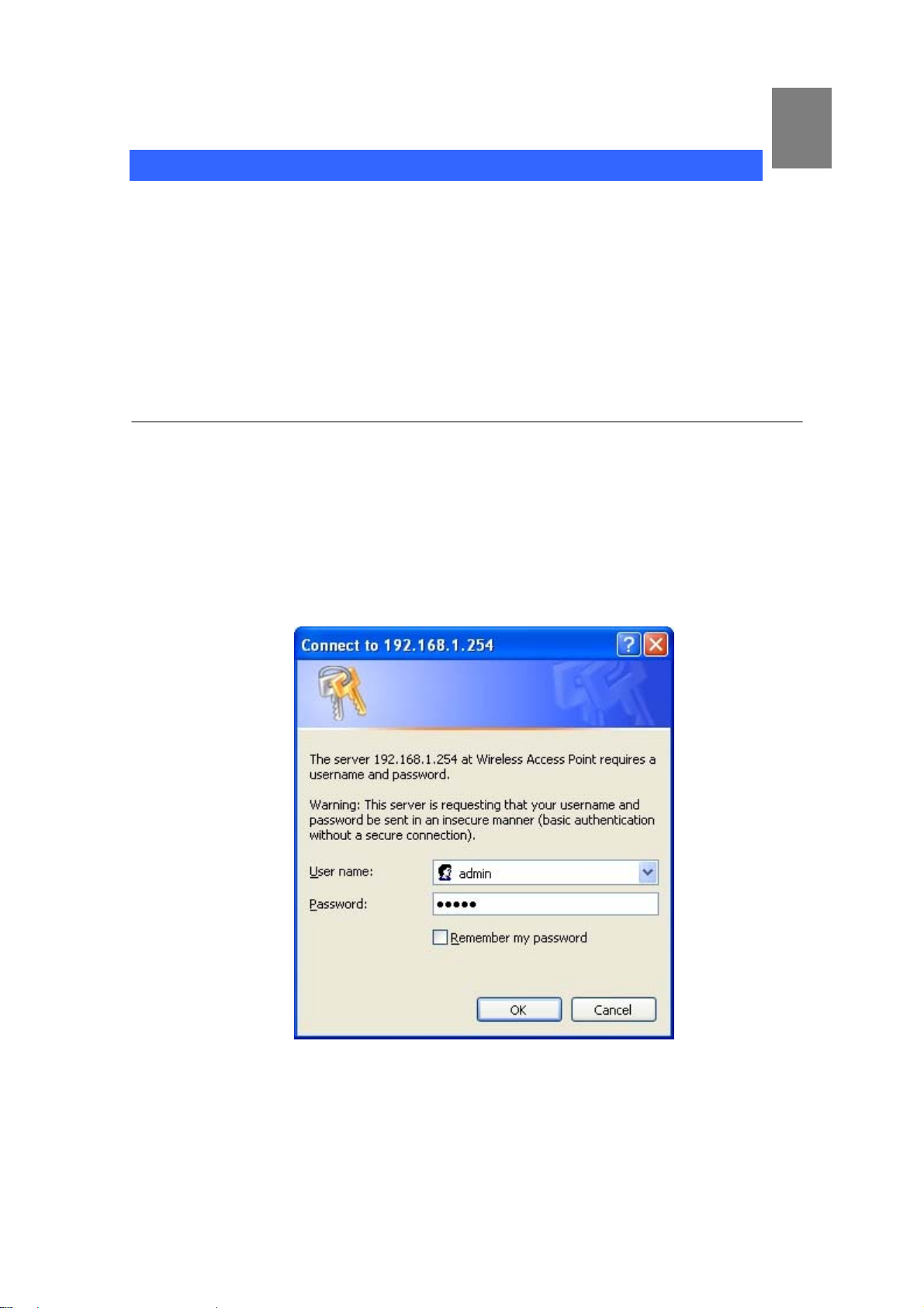
You will connect to Access Point via your web browser automatically. Access Point will prompt for logon
username / password, please enter: admin / admin to continue machine administration.
Access Point will prompt for logon username/password, please enter: admin / admin to continue
machine administration.
The default IP address of LAN port is 192.168.1.254. You also could open your web browser , and insert
- 9 -
Page 10

http://192.168.1.254 in the address bar of your web browser to logon Access Point web configuration
page.
To start Access Point web configuration, you must have one of these web browsers installed on
computer for management
Microsoft Internet Explorer 6.00 or higher with Java support
ÍNote
Please locate your PC in the same network segment
(192.168.1.x) of Router. If you’re not familiar with TCP/IP,
please refer to related chapter on user’s manual CD or consult
your network administrator for proper network
configurations.
- 10 -
Page 11

Chapter 3
Network Settings
3
Configuring and monitoring your Access Point from web
browser
The Access Point integrates a web-based graphical user interface that can cover most configurations
and machine status monitoring. Via standard web browser, you can configure and check machine
status from anywhere around the world.
Overview on the web interface of Access Point
With web graphical user interface, you may have:
More comprehensive setting feels than traditional command line interface.
Provides user input data fields, check boxes, and for changing machine configuration setting s
Displays machine running configuration
To start Access Point web configuration, you must have one of these web browsers installed on
computer for management
Microsoft Internet Explorer 6.00 or higher with Java support
Manipulation of Access Point via web browser
Log on Access Point via web browser
After TCP/IP configurations on your PC, you may now open your web browser , and input
http://192.168.1.254
The Access Point will prompt for logon username/password: admin / admin
(Default LAN port IP address) to logon Access Point web configuration page.
- 11 -
Page 12
Access Point login prompt screen
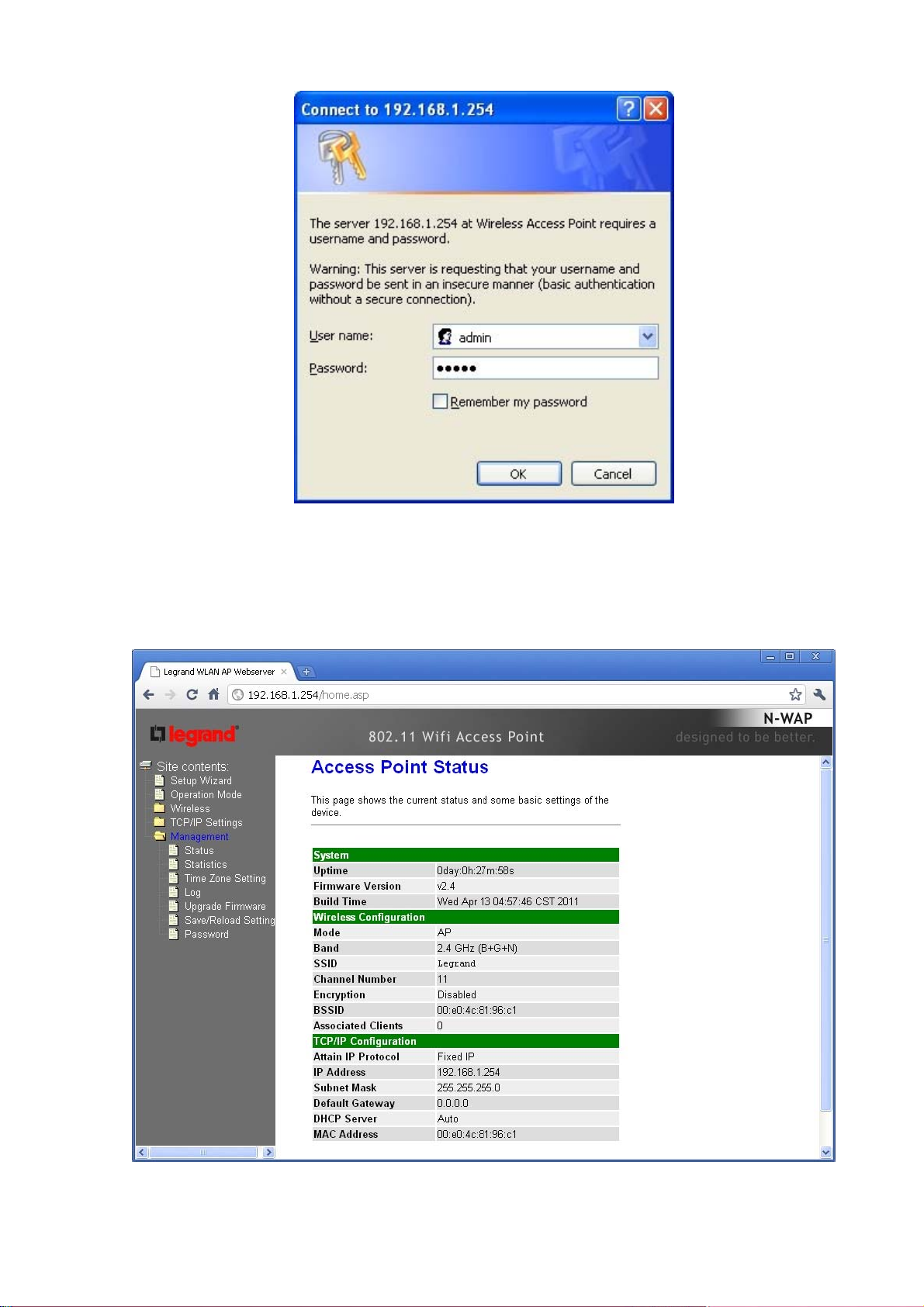
When users login the web page, users can see the general information like company…etc in this main
page.
Access Point main page
- 12 -
Page 13
Starting Setup in Web UI
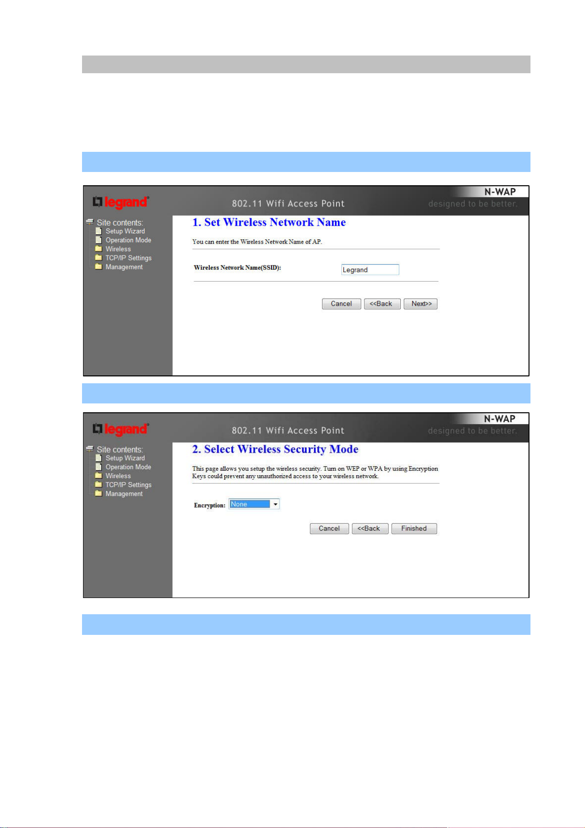
It is easy to configure and manage the AP/ Router with web browser. After successfully login, you can
click Setup Wizard to quickly configure your AP/ Router.
AP Mode
Step 1. Set Wireless Network Name (SSID), and then click Next>>.
Step 2. Select Wireless Security Mode.
Step 3. Click the Finished button. You will then see the Finish page as shown below.
The AP will reboot autom atically to make your wirele ss configuration to take ef fe ct and finish the Setup.
.
- 13 -
Page 14
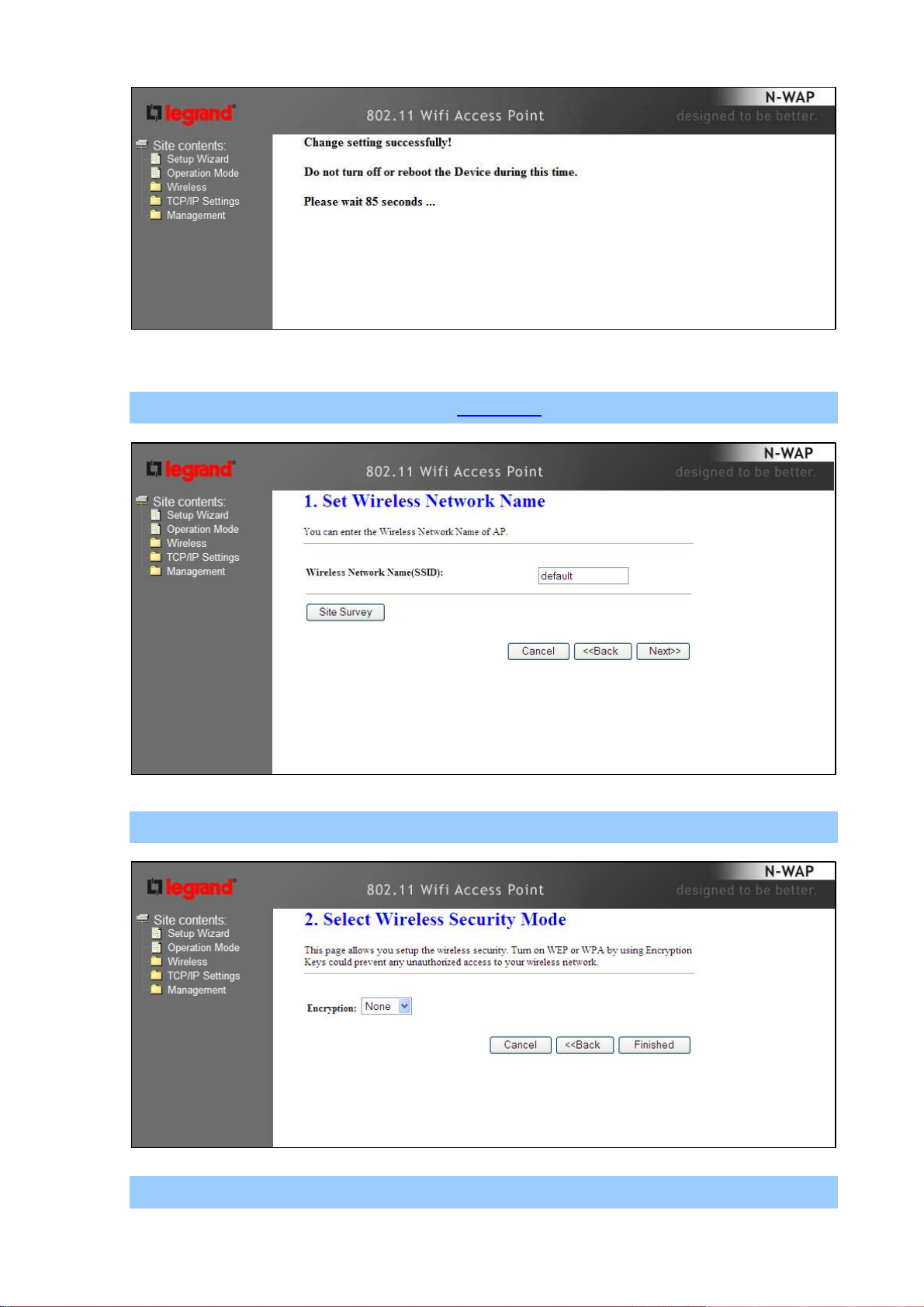
Client Mode
Step 1. Set Wireless Network Name, or click Site Survey to scan the nearby AP.
Step 2. Select Wireless Security Mode.
Step 3. Click the Finished button. You will then see the Finish page as shown below.
- 14 -
Page 15
The AP will reboot autom atically to make your wirele ss configuration to take ef fe ct and finish the Setup.
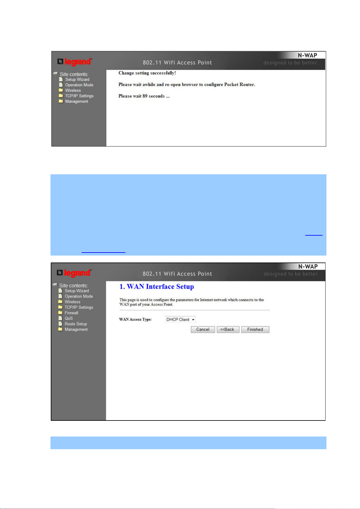
Router Mode
Step 1. Select the WAN Access Type.
Step 2. Enter the information for the selected WAN Access Type, and then click Next. If your access
type is DHCP Client, then you can get the IP address from the ISP, so you do not need to
enter the information like other modes. For other modes, please refer to the section WAN
Interface Setup.
Step 3. Click the Finished button. You will then see the Finish page as shown below.
The AP will reboot autom atically to make your wirele ss configuration to take ef fe ct and finish the Setup.
- 15 -
Page 16
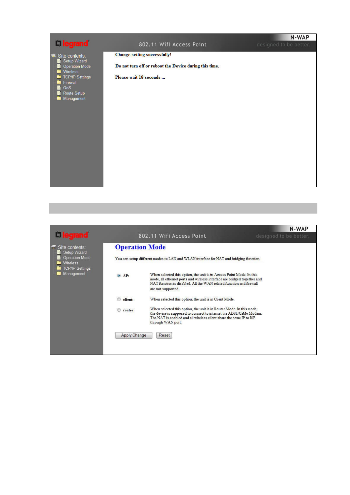
Network Operation Mode
You can setup different modes to WAN and LAN interface for NAT, Bridging and Wireless ISP function.
- 16 -
Page 17
In this mode, all Ethernet ports are bridged together and NAT function
AP
is disabled. All the LAN port related function and firewall are not
supported.
In this mode, all Ethernet ports are bridged together and the wireless
client will connect to ISP access point. The NAT is enabled and PCs in
Client
Ethernet ports share the same IP to ISP through wireless LAN. You
must set the wireless to client mode first and connect to the ISP AP in
Site-Survey page.
In this mode, the device is supposed to connect to internet via
ADSL/Cable Modem. The NAT is enabled and your PC in LAN port
Router
shares the same IP to ISP through WAN port. The connection type
can be setup in WAN page by using Static, DHCP Client, PPPOE,
PPTP or L2TP.
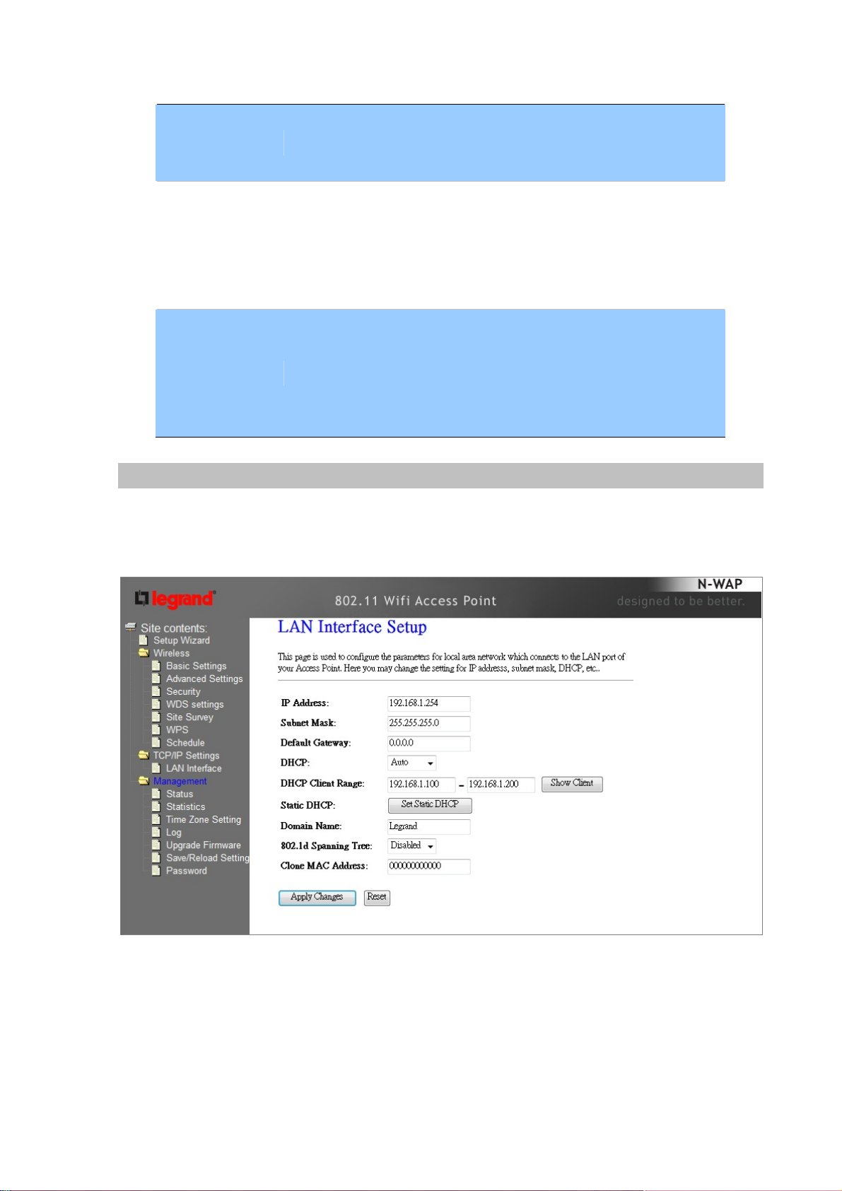
LAN Interface Setup
This page is used to configure the parameters for local area network which connect s to the LAN port of
your Gateway. Here you may change the setting for IP address, subnet mask, DHCP, etc..
- 17 -
Page 18

IP Address
LAN IP Address of the Access Point
Default : 192.168.1.254
Subnet Mask
DHCP Server
DHCP Client Range
Static DHCP
Domain Name
802.11d Spanning Tree
LAN mask of the Access Point
Default : 255.255.255.0
You can select Server or Disable. If you select Disable, the
DHCP service of LAN port is disabled.
Default : Server
The first and last IP address that DHCP serve r assigns.
Default : 192.168.1.100 – 192.168.1.200
It allows you reserve IP addresses, and assign the same IP
address to the network device with the specified MAC address
any time it requests an IP address
Default : Disable
Set three alternatives Domain Name Server for LAN interface.
Default : Null
Spanning Tree Protocol. You can select Enable or Disable.
Default : Disable
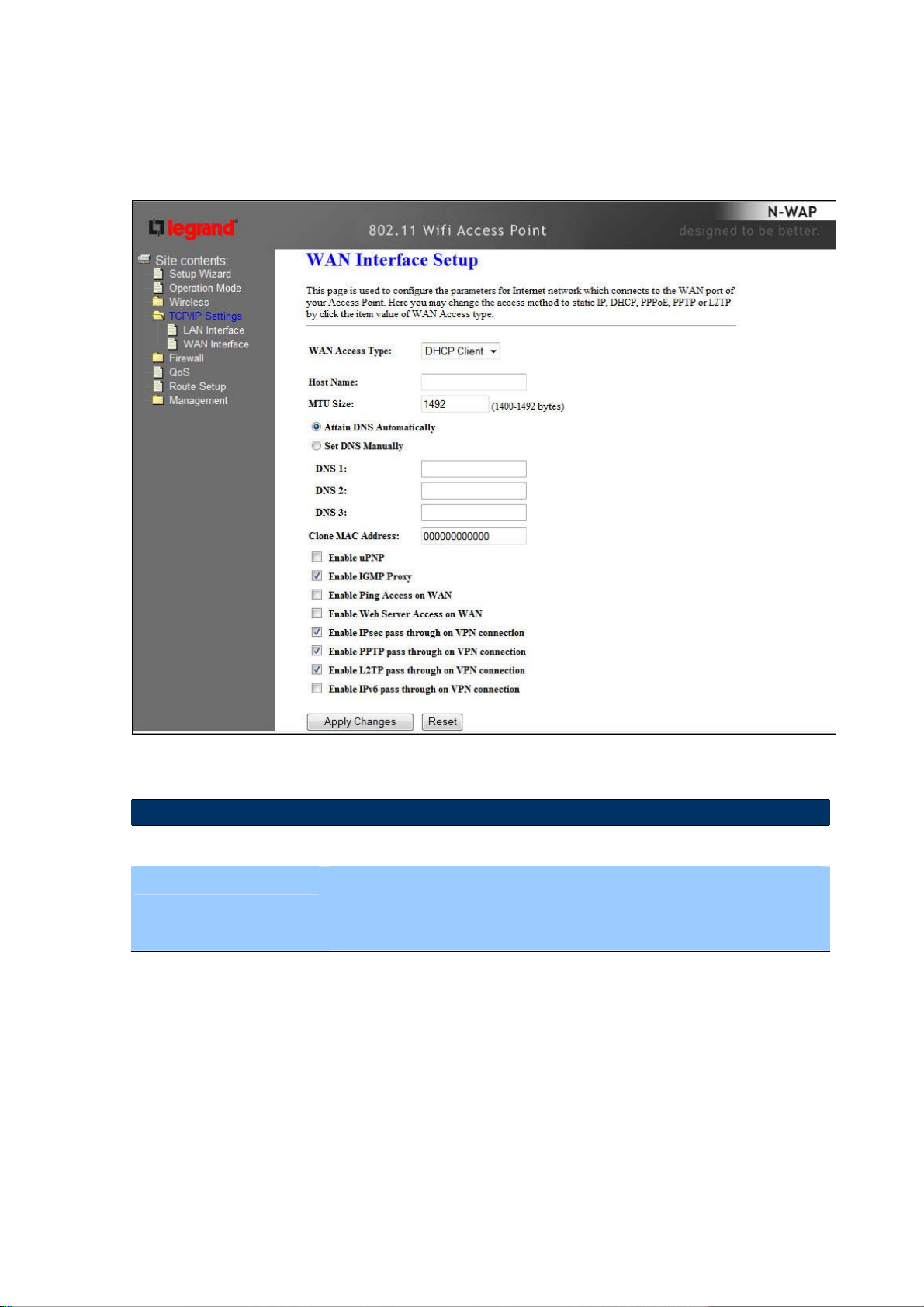
WAN Interface Setup
Choose menu “TCP/IP Settings→WAN Interface”, you can configure the IP parameters of the WAN
on the screen below when router mode is enabled.
- 18 -
Page 19

DHCP Client
Connections which use dynamic IP address assignment.
WAN Access Ty pe
Attain DNS Automatically
Set DNS Manually
Clone MAC Address
Static IP
Connections which use static IP address assignment.
Connections which use PPPoE that requires a user
PPPoE
name and password.
Connections which us e
a Point-to-Point Tunneling Protocol
PPTP
(PPTP) connection.
Connections which use
a Layer2 Tunneling Protocol (L2TP)
L2TP
connection.
Select to attain DNS automatically from your ISP.
Select to specify your own preferred DNS Server IP address.
The DNS 2 or DNS 3 is optional. You can enter the secondary and the
third DNS Server’s IP address as an alternative of DNS 1.
Your ISP may require a particular MAC address in order for you to
connect to the Internet. This MAC address is the PC’ s MAC addre s s that
your ISP had originally connected your Internet to. Type in this section to
replace the WAN MAC address with the MAC address of that PC.
Enable uPNP
Enable IGMP Proxy
Enable Ping Access on
WAN
Enable Web Server
Access on WAN
Enable IPsec pass
through on VPN
connection
Enable PPTP pass
through on VPN
connection
Enable L2TP pass throug h
on VPN connection
Enable IPv6 pass through
on VPN connection
Check to enable the uPNP function.
Check to enable the IGMP Proxy function.
Check to enable the Ping Access on WAN function.
Check to enable the Web Server Access on WAN function.
Check to enable the IPsec pass through on VPN connection
function.
Check to enable the PPTP pass through on VPN connection
function.
Check to enable the L2TP p ass through on VPN connection function.
Check to enable the IPv6 pass through on VPN co nnection function.
Apply Changes
After completing the settings on this page, click Apply changes button
to save the settings.
Reset
Click Reset to restore to default values.
- 19 -
Page 20
DHCP Client
If your ISP provides the DHCP service, please choose DHCP Client type, and the Router will
automatically obtain IP parameters from your ISP. You can see the page as follows.
The page includes the following fields:
Object Description
Host Name
This option specifies the Host Name of the Router.
MTU Size The default MTU (Maximum Transmission Unit) value is 1492
Bytes. It is not recommended that you change the default MTU Size
unless required by your ISP.
Static IP
If your ISP provides a static or fixed IP Address, then you have to setup the IP address, Subnet Mask,
Gateway and DNS setting. You can see the page as follows.
- 20 -
Page 21

The page includes the following fields:
Object Description
IP Address
Subnet Mask
Enter the IP address in dotted-decimal notation provided by your ISP.
Enter the subnet Mask in dotted-decimal notation provided by your ISP,
usually is 255.255.255.0
Default Gateway
(Optional) Enter the gateway IP address in dotted-decimal notation
provided by your ISP.
MTU Size
The normal MTU (Maximum Transmission Unit) value for most
Ethernet networks is 1500 Bytes. It is not recommended that you
change the default MTU Size unless required by your ISP.
DNS 1
Enter the DNS server IP address provided by your ISP, or you can
specify your own preferred DNS server IP address.
DNS 2 & DNS 3
You can enter another DNS server’s IP address as a backup. DNS 2
and 3 servers will be used when the DNS 1 server fails.
- 21 -
Page 22

PPPoE
If your ISP provides a PPPoE connection, select PPPoE option. User has to setup the user name and
password according to the ISP that provided the related information. You can see the pag e as follows.
The page includes the following fields:
Object Description
User Name
Password
Service Name
Connection T ype
Enter the User Name provided by your ISP. This field is case-sensitive.
Enter the Password provided by your ISP. This field is case-sensitive.
Enter the Internet service provider name in this field.
Select the connection type Continuous, Connect on Demand or
Manual from the drop-down menu. If selected Manual, user can click
Connect button to make a connection.
Idle Time
It represents that the device will idle after the minutes you set. The
time must be set between 1~1000 minutes. Default value of idle time
- 22 -
Page 23

is 5 minutes. This function will be available when the Connection Type
is selected to Connect on Demand.
MTU Size
PPTP
The default MTU (Maximum Transmissi on Unit) value is 1452 Bytes. It
is not recommended that you change the default MTU Size unless
required by your ISP.
If your ISP provides PPTP connection, please select PPTP option. And enter the following parameters.
You can see the page as follows.
The page includes the following fields:
Object Description
IP Address
- 23 -
Enter the IP address in dotted-decimal notation provided by your ISP.
Page 24

Subnet Mask
Enter the subnet Mask in dotted-decimal notation provided by your ISP,
usually is 255.255.255.0
Server IP Address
User Name
Password
Connection T ype
Idle Time
MTU Size
Enter the PPTP Server IP address in dotted-decimal not ation provided
by your ISP.
Enter the User Name provided by your ISP. The Maximum input is 20
alphanumeric characters (case-sensitive).
Enter the Password provided by your ISP. The Maximum input is 32
alphanumeric characters (case-sensitive).
Select the connection type Continuous, Connect on Demand or
Manual from the drop-down menu. If selected Manual, user can click
Connect button to make a connection.
It represents that the device will idle after the minutes you set. The
time must be set between 1~1000 minutes. Default value of idle time
is 5 minutes. This function will be available when the Connection Type
is selected to Connect on Demand.
The default MTU (Maximum Transmissi on Unit) value is 1460 Bytes. It
is not recommended that you change the default MTU Size unless
required by your ISP.
L2TP
If your ISP provides L2TP connection, please select L2TP option. And enter the following parameters.
You can see the page as follows.
- 24 -
Page 25

The page includes the following fields:
Object Description
IP Address
Subnet Mask
Enter the IP address in dotted-decimal notation provided by your ISP.
Enter the subnet Mask in dotted-decimal notation provided by your ISP,
usually is 255.255.255.0
Server IP Address
Enter the L2TP Server IP address in dotted-decimal notation provided
by your ISP.
User Name
Enter the User Name provided by your ISP. The Maximum input is 20
alphanumeric characters (case-sensitive).
Password
Enter the Password provided by your ISP. The Maximum input is 32
alphanumeric characters (case-sensitive).
Connection T ype
Select the connection type Continuous, Connect on Demand or
- 25 -
Page 26

Manual from the drop-down menu. If selected Manual, user can click
Connect button to make a connection.
Idle Time
MTU Size
It represents that the device will idle after the minutes you set. The
time must be set between 1~1000 minutes. Default value of idle time
is 5 minutes. This function will be available when the Connection Type
is selected to Connect on Demand.
The default MTU (Maximum Transmissi on Unit) value is 1460 Bytes. It
is not recommended that you change the default MTU Size unless
required by your ISP.
- 26 -
Page 27

Chapter 4
Firewall
Port Filtering
Entries in this table are used to restrict certain types of data p ackets from your local network
to Internet through the Gateway. Use of such filters can be helpful in securing or restricting your local
network.
4
- 27 -
Page 28

Enable Port Filtering
A
Check to enable Port Filtering function.
Enter the beginning of the range of port numbers used by the service. If
Port Range
Protocol
Comment
Apply Changes
Reset
Current Filter Table
Delete Selected
Delete All
the service uses a single port number, enter it in both the start and finish
fields.
Select the protocol (TCP, UDP or Both) used to the remote system or
service.
You may key in a description MAC address.
fter completing the settings on this page, click Apply Changes button to
save the settings.
Click Reset button to restore to default values.
Shows the current Port Forwarding information.
Click Delete Selected button to delete items which are selected.
Click Delete All button to delete all the items.
Reset
Click Reset button to reset.
IP Filtering
Entries in this table are used to restrict certain types of data packets from your local network to Internet
through the Gateway. Use of such IP filters can be helpful in securing or restricting your local network.
- 28 -
Page 29

A
Enable IP Filtering
Local IP Address
Protocol
Comment
Apply Changes
Reset
Current Filter Table
Delete Selected
Delete All
Check to enable IP filtering function.
Enter the local computer’s IP address.
Select the protocol (TCP, UDP or Both) used to the remote system or
service.
You may key in a description for the port range.
fter completing the settings on this page, click Apply Changes button to
save the settings.
Click Reset button to restore to default values.
Shows the current IP filter information.
Click Delete Selected button to delete items which are selected.
Click Delete All button to delete all the items.
Reset
Click Reset button to rest.
- 29 -
Page 30

MAC Filtering
A
Entries in this table are used to restrict certain types of data packets from your local network to Internet
through the Gateway. Use of such filters can be helpful in securing or restricting your local network.
Enable MAC Filtering
MAC Address
Comment
Apply Changes
Reset
Current Filter Table
Deleted Selected
Deleted All
Check to enable MAC filtering function.
Enter the client MAC address in the field.
You may key in a description MAC address.
fter completing the settings on this page, click Apply Changes button to
save the settings.
Click Reset button to restore to default values.
Shows the current MAC filter information.
Click Delete Selected button to delete items which are selected.
Click Delete All button to delete all the items.
Reset
Click Reset button to rest.
Port Forwarding
Entries in this table allow you to automatically redirect common network servi ce s to a specific machine
behind the NA T firewall. These setting s are only necessary if you wish to host some sort of server like a
- 30 -
Page 31

web server or mail server on the private local network behind your Gateway's NAT firewall.
- 31 -
Page 32

Enable Port Forwarding
A
Check to enable Port Forwarding function.
IP Address
Protocol
Port Range
Comment
Apply Changes
Reset
Current Port Forwading
Table
Enter the IP address in the field.
Select the protocol (TCP, UDP or Both) used to the remote system or
service.
For TCP and UDP Services, enter the beginning of the range of port
numbers used by the service. If the service uses a
single port number, enter it in both the start and finish fields.
You may key in a description MAC address.
fter completing the settings on this page, click Apply Changes button to
save the settings.
Click Reset button to restore to default values.
Shows the current Port Forwarding information.
Delete Selected
Delete All
Reset
Click Delete Selected button to delete items which are selected.
Click Delete All button to delete all the items.
Click Reset button to rest.
URL Filtering
URL filter is used to deny LAN users from accessin g the internet. Block those URLs which contain
keywords listed below .
- 32 -
Page 33

A
Enable URL Filtering
URL Address
Check to enable URL filtering function.
Enter the URL address in the field.
fter completing the settings on this page, click Apply Changes button to
Apply Changes
save the settings.
Reset
Current Filter Table
Delete Selected
Reset
Click Reset button to restore to default values.
Shows the current URL address filter information.
Click Delete All button to delete all the items.
Click Reset button to rest.
DMZ
A Demilitarized Zone is used to provide Internet services without sacrificing unauthorized access to its
local private network. Typically, the DMZ host contains devices accessible to Internet traffic, such as
Web (HTTP ) serve rs, FTP servers, SMTP (e-mail) servers and DNS serv ers.
- 33 -
Page 34

Check the box to enable DMZ function. If the DMZ Host Function is
Enable DMZ
DMZ Host IP Address
Apply Changes
Reset
enabled, it means that you set up DMZ host at a particular computer to
be exposed to the Internet so that some applications/software, especially
Internet / online game can have two way connections.
Enter the IP address of a particular host in your LAN which will receive all
the packets originally going to the WAN port/Public IP address above.
After completing the settings on this page, click Apply Changes button to
save the settings.
Click Reset button to restore to default values
- 34 -
Page 35

Chapter 5
Wireless Settings
Basic Settings
This page is used to configure the parameters for wireless LAN cli ents who may connect to
your Access Point. Here you may change wireless encryption settings as well as wireless ne t work
parameters.
5
Disable Wireless LAN
Interface
Band
- 35 -
Enable or disable the wireless LAN.
There are 6 modes: 2.4GHz (B), 2.4GHz (G), 2.4GHz (N), 2.4GHz
(B+G), 2.4GHz (G+N), and 2.4GHz (B+G+N) mode.
Default : 2.4GHz (B+G+N)
Page 36

Mode
- AP: The AP functions as a wireless hub to which wireless clients
can connect. The clients must make sure that they are configured
to match the AP’s wireless settings. The AP must be connected to
switch or other LAN segment patch cable.
- WDS: WDS operation as defined by the IEEE802.11 standard
has been made available. Using WDS it is possible to wirelessly
connect Access Points, and in doing so extend a wired
infrastructure to locations where cabling is not possible or
inefficient to implement.
- AP+WDS: It means the device can support WDS and AP Mode
simultaneously.
Default : AP mode
Network Type -
SSID
Channel Width
Control Sideband
- Infrastructure: The wireless LAN serves as a wireless station
(infrastructure). Connected to a PC or a small LAN (no more than 5
PCs), it allows the PC or small LAN able to access the wireless
network via Access Point.
- Ad hoc: The wireless LA N will use the Ad hoc mode to operate.
Wireless stations associating to the access point must have the
same SSID. Enter a descriptive name for the wireless LAN.
Default : 802.11bgn-SSID
There are 20MHz and 40MHz bandwidt hs for cohesion
Default : 20MHz
Specify if the extension channel should be in the Upper or Lower
sideband
Default : Upper (Unavailable)
- 36 -
Page 37

Domain Region
The Domain Region decides what channels are available for your
country. Please note that using the incorrect Domain Region is
strictly prohibited. If you live in United States, you must use the FCC
Domain Region. If you live inside EU, you must use ETSI domain.
Domain Region Available Channels
FCC (U.S.) 20MHz: 1~11
40MHz: 5~11
IC (Canada) 20MHz: 1~11
40MHz: 5~11
ETSI (EMEA) 20MHz: 1~13
40MHz: 5~13
SPAIN 20MHz: 10, 11
40MHz: 11
FRANCE 20MHz: 10~13
40MHz: 13
MKK (Japan) 20MHz: 1~14
Channel Number
Broadcast SSID
40MHz: 5~14
Default : FCC
Select the appropriate channel from the list provided to correspond
with your network settings. Channels differ from country to country.
Default : Auto
If you enable “Broadcast ESSID”, every wireless station located
within the coverage of this access point can discover this Access
Point easily. If you are building a public wireless network, enabling
this feature is recommended. In private network, disabling
“Broadcast ESSID” can provide better security.
Default : Enable
- 37 -
Page 38

WMM
The short of Wi-Fi Multi-Media, it will enhance the data transfer
performance of multimedia contents when they’re being transferred
over wireless network.
Default : Enable (Unavailable)
Data Rate
Associated Clients
Enable Mac Clone
Enable Universal
Repeater Mode
SSID of Extended
Interface
The Data Rate is the rate of data transmission for 802.11b/g/n
clients. The Access Point will use the highest possible selected
transmission rate to transmit the data packets.
Default : Auto
Default : Auto
To show the MAC address, transmission, reception packet counters
and encrypted status for each associated wireless cli ent.
When set at Client mode, it provides wireless LAN to connect to a
MAC address.
Default : Disable
Universal Repeater is a technology used to extend wireless
coverage.
Default : Disable
Universal Repeater is a technology used to extend wireless
coverage. To enable Universal Repeater Mode, check the box and
enter the SSID you want to broadcast in the field below. Then please
click “Security” submenu for the related settings of the AP you want
to connect with. It is only available in Client Mode.
Default : Null
Multiple APs
Multiple APs/SSIDs allow the ability for separate security mode and key settings to be set by users for
both convenience and increased protection. Users are able to configure their network devices to
access the first SSID with the WPA2 PSK (Pre-Shared Key) and secret key, whilst share the second
SSID with WEP and the periodically changed key for visitors. In addition, users are able to isolate these
SSIDs to avoid malicious attacks and prevent certain access for visitors using the second SSID. This
then provides users an extremely convenient approach to share the wireless access, provide access
internet access for visitors, while possessing a strong security protection system at all times.
In Wireless Basic Settings page, click the Multiple AP button. You will then see the Multiple APs
Settings page as shown below.
- 38 -
Page 39

- 39 -
Page 40

Enable Multiple APs
Check the checkbox to enable the Multiple AP/SSID.
Up to 4 SSIDs for each BSS can be entered in the filed SSID. The name
can be up to 32 characters. T he same name (SSID) mus t be assigned
to all wireless devices in your network. If Enable VLAN is checked, the
wireless stations connecting to SSID of different VID can not
communicate with each other.
VLAN Settings
Entries in below table are used to config vlan settings. VLANs are created to provide the segmentation
services traditionally provided by routers. VLANs address issues such as scalability, security, and
network management.
In Wireless Basic Settings page, click the Multiple AP button. You will then see the VLAN Settings
page as shown below.
- 40 -
Page 41

Enable VLAN
VLAN (Virtual Local Area Network) refers to a group of logically
networked devices on one or more LANs that are configured so that they
can communicate as if they were attached to the same wire, when in fact
they are located on different LAN segments. Because VLANs are based
on logical instead of physical connections, it is very flexible for user/host
management.
VID
Provide a number between 1 and 4090 for VLAN. This will cause the AP
to send packets with VLAN tags. The switch connecting with the AP
must support VLAN IEEE802.1Q frames. The wireless stations
connecting to the SSID of a specified VLANID can communicate with
the PC connecting to the port with the same VLANID on the Switch.
Advanced Settings
These settings are only for more technically advanced users who have a sufficie nt knowledge about
wireless LAN. These settings should not be changed unless you know what effect the changes will
have on your Access Point.
- 41 -
Page 42

Fragment Threshold
RTS Threshold
Beacon Interval
Preamble Type
“Fragment Threshold” specifies the maximum size of packet during
the fragmentation of data to be transmitted. If you set this value too
low, it will result in bad performance.
Default : 2346
When the packet size is smaller the RTS threshold, the access point
will not use the RTS/CTS mechanism to send this packet.
Default : 2347
The interval of time that this access point broadcast a beacon.
Beacon is used to synchronize the wireless network.
Default : 100
Preamble type defines the length of CRC block in the frames during
the wireless communication. “Short Preamble” is suitable for high
traffic wireless network. “Long Preamble” can provide more reliable
communication.
Default : Long Preamble
- 42 -
Page 43

IAPP
Inter-Access Point Protocol is a recommendation that describes an
optional extension to IEEE 802.11 that provides wireless
access-point communications among multivendor systems.
Default : Enable
Protection
Aggregation
Short GI
WLAN Partition
It is recommended to enable the protection mechanism. This
mechanism can decrease the rate of data collision between 802.11b
and 802.1 1g wirel ess stati ons. When the protection mode i s enabled,
the throughput of the AP will be a little lower due to many of frame
traffic should be transmitted.
Default : Enable
It is a function where the values of multiple rows are grouped
together.
Default : Enable
It is used to set the time that the receiver waits for RF reflections to
settle out before sampling data.
Default : Enable
This feature also called WLAN isolation or Block Relay. If this feature
is disabled, then there is no barrier between communications among
wireless stations connecting to the Access Point, i.e the Access
Point. If this is enabled, wireless stations of the selected band are not
allowed to exchange data through the Access Point. The default
value is set to 'Disabled'.
Default : Disable
RF Output Power
Users can adjust the output power to 100%, 75% 50% 35% and
15%.
Default : 100%
Security Setup
This page allows you setup the wireless security. Turn on WEP or WPA by using Encryption Keys could
prevent any unauthorized access to your wireless network.
- 43 -
Page 44

Select SSID
Encryption
802.1x Authentication
If assigned multiple AP feature, you could choose the SSID that want to
setup encryption function.
Select the data privacy algorithm you want. Enabling the security can
protect your data while it is transferred from one station to another.
Default : Disable
Check Box was used to switch the function of the 802.1X. When the
802.1X function is enabled, the Wireless user must authenticate to this
router first to use the Network service.
Default : Uncheck
- WEP
When you select the 128 or 64 bit WEP key security, please select one WEP key to be used and input
26 or 10 hexadecimal (0, 1, 2…8, 9, A, B…F) digits.
- 44 -
Page 45

- WPA
When select the WPA function, the Wireless user must authenticate to this router first to use the
Network service. RADIUS Server IP address or the 802.1X server’s domain-name.
If you select HEX, you have to fill in 64 hexadecimal (0, 1, 2…8, 9, A, B…F) digits
If ASCII, the length of pre-share key is from 8 to 63.
Key value shared by the RADIUS server and this router. This key value is consistent with the key value in the
RADIUS server.
- WPA2
When select the WPA function, the Wireless user must authenticate to this router first to use the
Network service. RADIUS Server IP address or the 802.1X server’s domain-name.
If you select HEX, you have to fill in 64 hexadecimal (0, 1, 2…8, 9, A, B…F) digits
If ASCII, the length of Pre-share key is from 8 to 63.
Key value shared by the RADIUS server and this router. This key value is consistent with the key value in the
RADIUS server.
- 45 -
Page 46

- WPA-Mixed
When select the WP A-Mixed function, the Wireless user must authenticate to this router first to use the
Network service. RADIUS Server
The router will detect automatically which Security type (WPA-PSK version 1 or 2) the client uses to encrypt.
IP address or the 802.1X server’s domain-name.
If you select HEX, you have to fill in 64 hexadecimal (0, 1, 2…8, 9, A, B…F) digits
If ASCII, the length of Pre-share key is from 8 to 63.
Key value shared by the RADIUS server and this router. This key value is consistent with the key value in the
RADIUS server.
- 46 -
Page 47

Access Control
If you choose 'Allowed Listed', only those clients whose wireless MAC addresses are in the access
control list will be able to connect to your Access Point. When 'Deny Listed' is selected, these wireless
clients on the list will not be able to connect the Access Point.
WDS Settings
Wireless Distribution System uses wireless media to communicate with other APs, like the Ethernet
does. To do this, you must set these APs in the same channel and set MAC address of other APs which
you want to communicate with in the table and then enable the WDS.
- 47 -
Page 48

Site Survey
This page provides tool to scan the wireless network. If any Access Point or IBSS is found, you could
choose to connect it manually when client mode is enabled.
WPS Settings
Wi-Fi Protected Setup (WPS) is the simplest way to build connection between wireless network clients
and this wireless router. You don’t have to select encryption mode and input a long encryption pass
phrase every time when you need to setup a wireless client, you only have to press a button on
wireless client and router, and the WPS will do the rest for you.
- 48 -
Page 49

This wireless router supports two types of WPS: Push-Button Configuration (PBC), and PIN code. If
you want to use PBC, you have to push a specific button on the wireless client to start WPS mode, and
switch this wireless router to WPS mode too. You can push RET/WPS button of this wireless router, or
click ‘Start PBC’ button in the web configuration interface to do this. If you want to use PIN code, you
can see the setup as below.
Disable WPS
WPS Status
Self-PIN Number
Push Button
Configuration
Client PIN Number
Check this box to disable WPS function, uncheck it to enable WPS.
If the wireless security (encryption) function of this wireless router is
properly set, you’ll see ‘Configured’ message here. If wireless
security function has not been set, you’ll see ‘unConfigured’.
This is the WPS PIN code of this wireless router. This code is useful
when router sets as Enrollee, you need to fill this number into the
web page of the other device.
Click ‘Start PBC’ to start Push-Button style WPS setup procedure.
This wireless router will wait for WPS requests from wireless clients
for 2 minutes. The ‘WLAN’ LED on the wireless router will be steady
on when this wireless router is waiting for incoming WPS request.
Please input the PIN code of the other device you wish to connect,
and click ‘St art PIN’ button. The ‘WLAN’ led on the wireless router will
be steady on when this wireless router is waiting for incoming WPS
request. (Please see the detail as below.)
- PBC setup step:
- 49 -
Page 50

1. Ensure you have set the security setting on Access Point (as Registrar).
2. Click the WPS button on Access Point (or the “S tart PBC” button on the web interface of Access
Point) and the other device (supports PBC function) in 2 minutes.
3. Access Point (Registrar) would send SSID and security key to the other device (Enrollee) through
tunnel to connect.
4. If you see the wireless client in the list, WPS-PBC setting is successful.
- PIN (as register) setup step:
1. Fill the PIN code of the other device (as Enrollee that support WPS-PIN setting) into the “Client PIN
Number” of Access Point.
2. Click the “Start PIN” buttons on Access Point and the other device in 2 minutes.
3. If you see the wireless client in the list, WPS-PIN setting is successful.
- PIN (as Enrollee) setup step:
1. Fill the PIN code of Access Point into the other device (as Registrar).
2. Click the “Start PIN” buttons on Access Point and the other device in 2 minutes.
3. If you see the wireless client in the list, WPS-PIN setting is successful.
- 50 -
Page 51

** As the figure as above, just change two roles.
Wireless Schedule
This page allows you setup the wireless schedule rule. Please do not forget to configure system time
before enable this feature.
- 51 -
Page 52

Chapter 6
Management
Status
In this page can show the current status and some basic settings of the Access Point.
6
Statistics
This page shows the packet counters for transmission and reception regarding to Ethernet n etworks.
- 52 -
Page 53

DDNS
Choose menu “Dynamic DNS”, and you can configure the Dynamic DNS function when enabled router
mode.
The Router offers the DDNS (Dynamic Domain Name System) feature, which allows the hosting of a
website, FTP server, or e-mail server with a fixed domain name (named by yourself) and a dynamic IP
address, and then your friends can connect to your server by entering your domain name no matter
what your IP address is. Before using this feature, you nee d to sign up for DDNS servi ce providers such
as www.comexe.cn
, www.dyndns.org, or www.no-ip.com. The Dynamic DNS client service provider will
give you a password or key.
To set up for DDNS, follow these instructions:
Step 1. Check Enable DDNS.
Step 2. Select the Service Provider from the drop-down menu.
Step 3. Type the Dom ain Nam e receive d from your dynamic DNS service provider.
Step 4. Type the User Name/Email for your DDNS account.
Step 5. Type the Password/Key for your DDNS account.
Step 6. Click the Apply Change button to apply the settings.
Time Zone Setting
You can maintain the system time by synchronizing with a public time server over the Internet.
- 53 -
Page 54

Current Time
Time Zone Select
Enable NTP client
update
Input current time manually.
Select local time zone according to location.
Check to enable NTP update. Once this function is enabled,
Access Point will automatically update current time from NTP
server.
NTP server
User may select prefer NTP sever or input address of NTP
server manually.
Denial-of-Service
DoS (Denial of Service) attacks can flood your Internet connection with invalid packets and connection
requests, using so much bandwidth and so many resources that Internet access becomes unavailable.
The Wireless Router incorporates protection against DoS attacks. This screen allows you to configure
DoS protection.
- 54 -
Page 55

Log
This page can be used to set remote log server and show the system log.
- 55 -
Page 56

Enable Log
Check to enable log function.
System all
Wireless
DoS
Enable Remote Log
Log Server IP Address
Activates all logging functions.
Only logs related to the wireless LAN will be recorded.
Only logs related to the DoS protection will be recorded.
Only logs related to the Remote control will be recorded.
Only logs related to the server will be recorded.
Upgrade Firmware
This page allows you upgrade the Access Point firmware to new version. Please note, do not power off
the device during the upload because it may crash the system.
- 56 -
Page 57

Firmware Version
The current version is shown in this field.
Browse and select file you want to upgrade and press Upload
Select File
to perform upgrade.
Please wait till on screen shows related information after
upgrade finished.
Upload
Click the Upload button to perform the upgrade process.
Click Reset will clean all current configurations and return to
Reset
default values.
Save / Reload Settings
This page allows you save current settings to a file or reload the settings from the file which was saved
previously. Besides, you could reset the current configuration to factory default.
Save Settings to File
Load Settings from File
Reset Settings to Default
Save current settings to a file.
Browse a file and upload to reload settings.
Click Reset button to restore to factory default values.
Password Setup
This page is used to set the account to access the web server of Access Point. Empty user name and
password will disable the protection.
- 57 -
Page 58

User Name
Enter user name.
New Password
Confirmed Password
Input password for this user.
Confirm password again.
- 58 -
Page 59

Chapter 7
QoS
Enable QoS
Use this section to configure QoS. The QoS settings improve your online gaming experience by
ensuring that your game traffic is prioritized over other network traffic, such as FTP or Web.
7
Enable QoS
Automatic
Uplink/Download Speed
Manual Uplink/Download
Speed
QoS Rule Setting
Administrator can setup a QoS rule for specific user depends on IP or MAC address.
- 59 -
Check the box to enable the QoS function.
Check the box to enable the automatic uplink/ download speed
function.
User can manually enter the uplink/ download speed in the blank
field.
Page 60

Address Type
Local IP Address
MAC Address
Mode
Uplink Bandwidth (Kbps)
Downlink Bandwidth
(Kbps)
Comment
Select IP or MAC address type.
Depend on the address type that selected, user can enter the IP
address or MAC address of client to set up the bandwidth of the
transmission.
Select Guaranteed minimum bandwidth or Restricted maximum
bandwidth modes.
Enter the Uplink Bandwidth (Kbps) in the column.
Enter the Downlink Bandwidth (Kbps) in the column.
Enter the note for the setting.
- 60 -
Page 61

Chapter 8
Route Setup
Dynamic Route
Dynamic routing performs the same function as static routing except it is steadier. Dynamic routing
allows routing tables in routers to change as the possible routes change. There are several protocols
used to support dynamic routing including RIP and OSPF.
8
Enable Dynamic Route
NA T
Transmit
Receive
Static Route
To set static routers, enter the settings including route IP address, route mask, route gateway and the
- 61 -
Check the box to enable the Dynamic Route function.
Network Address Translation (NAT) selects to enable or disable
this function.
Select to enable or disable RIP protocol for transmit.
Select to enable or disable RIP protocol for receive.
Page 62

route Interface from LAN or WAN.
Enable Static Route
IP Address
Subnet Mask
Gateway
- 62 -
Check the box to enable the Static Route function.
Set up the IP address that would like to send the packets pass
through.
Set up the Subnet Mask that would like to send the packets pass
through.
Set up the gateway that would like to send the packets pass
through.
Page 63

It is used by a router to make routing decisions.
The metrics used by a router to make routing decisions. It is
typically one of many fields in a routing table. Router metrics can
Metric
Interface
contain any number of values that help the router determine the
best route among multiple routes to a destination. A router
metric typically based on information like path length, bandwidth,
load, hop count, path cost, delay, Maximum Transmission Unit
(MTU), reliability and communications cost.
Select the interface of the setting path.
- 63 -
Page 64

Appendix A Frequently Asked Questions List
If your Access Point is not functioning properly, you can refer to this chapter first for sample
troubleshooting before contacting your dealer. This can save your time and effort but if the symptoms
persist, please consult your dealer.
Q1: I forget my Access Point login username and / or password
A1:
1.) Restore Access Point to its factory default settings by pressing the “Reset” button which is at the
side panel of the device for 5 seconds or more.
- 64 -
Page 65

Appendix B Access Point Specifications (TBD)
Product 802.11n Wireless Access Point
Model N-WAP
Hardware
WLAN Standards IEEE 802.11 b/g/n
Wireless Frequency Range 2.4GHz ~ 2.4835 GHz
Operation Mode AP, Client, Router
Wireless Mode AP, WDS and AP+WDS mode
64/128 bit WEP data encryption,
WPA, WPA-PSK,
Security
Operating Frequencies /
Channel
Wireless Data Rate
Transmit Power
Receiver Sensitivity
Antenna 2 x Antenna
WDS WDS repeater support
LAN 1 x 10/100 Base-TX RJ-45 port
Protocols and Standard
Protocols
Security
Network and Configuration
Access Mode Static IP, DHCP Client, PPPoE, PPTP, L2TP
Configuration &
Management
Dimension (W x D x H)
Operating Environment 0~50 Degree C
Power Requirement
EMC/EMI
WPA2, WPA2-PSK,
WP A/WPA2 mix mode,
802.1x encryption and WPS PBC
USA/Canada: 2.412 GHz – 2.426 GHz (11 channels)
Europe: 2.412 GHz – 2.472 GHz (13 channels)
Japan: 2.412 GHz – 2.477 GHz (14 channels)
IEEE 802.11b: CCK (11Mbps,5.5Mbps), DQPSK (2Mbps), DBPSK
(1Mbps)
IEEE 802.11g: OFDM (54Mbps, 48Mbps, 36Mbps, 24Mbps, 18Mbps,
12Mbps, 9Mbps, 6Mbps)
IEEE 802.11n: 14/29/43/58/87/116/130/144Mps in 20MHz,
30/60/90/120/180/240/270/300Mbps in 40MHz
802.11b: 17dBm
802.11g: 15dBm
802.11n: 13dBm
802.11b: -86dBm @11M
802.11g: -72dBm @54M
802.11n (20MHz): -68dBm
802.11n (40MHz): -66dBm
TCP/IP, UDP/RTP/RTCP, HTTP, ICMP, ARP, DNS, DHCP,
NTP/SNTP
Password protection for system management
Web-Based Graphical User Interface
Remote management over the IP Network
Web-Based firmware upgrade
Backup and Restore Configuration file
5~90% humidity
- 65 -
 Loading...