

Page 1

Page 2

Copyright
Copyright 2012 by PLANET Technology Corp. All rights reserved. No part of this publication may be
reproduced, transmitted, transcribed, stored in a retrieval system, or translated into any language or computer
language, in any form or by any means, electronic, mechanical, magnetic, optical, chemical, manual or
otherwise, without the prior written permission of PLANET.
PLANET makes no representations or warranties, either expressed or implied, with respect to the contents
hereof and specifically disclaims any warranties, merchantability or fitness for any particular purpose. Any
software described in this manual is sold or licensed "as is". Should the programs prove defective following their
purchase, the buyer (and not this company, its distributor, or its dealer) assumes the entire cost of all necessary
servicing, repair, and any incidental or consequential damages resulting from any defect in the software. Further,
this company reserves the right to revise this publication and to make changes from time to time in the contents
hereof without obligation to notify any person of such revision or changes.
All brand and product names mentioned in this manual are trademarks and/or registered trademarks of their
respective holders.
Federal Communication Commission Interference Statement
This equipment has been tested and found to comply with the limits for a Class B digital device,
pursuant to Part 15 of FCC Rules. These limits are designed to provide reasonable protection
against harmful interference in a residential installation. This equipment generates, uses, and can
radiate radio frequency energy and, if not installed and used in accordance with the instructions, may cause
harmful interference to radio communications. However, there is no guarantee that interference will not occur in
a particular installation. If this equipment does cause harmful interference to radio or television reception, which
can be determined by turning the equipment off and on, the user is encouraged to try to correct the interference
by one or more of the following measures:
Reorient or relocate the receiving antenna.
1.
2. Increase the separation between the equipment and receiver.
3. Connect the equipment into an outlet on a circuit different from that to which the receiver is connected.
4. Consult the dealer or an experienced radio technician for help.
FCC Caution:
To assure continued compliance, (example-use only shielded interface cables when connecting to computer or
peripheral devices) any changes or modifications not expressly approved by the party responsible for
compliance could void the user’s authority to operate the equipment.
This device complies with Part 15 of the FCC Rules. Operation is subject to the Following two conditions:
(1) This device may not cause harmful interference
(2) This Device must accept any interference received, including interference that may cause
undesired operation.
Any changes or modifications not expressly approved by the party responsible for compliance could
void the user’s authority to operate the equipment.
I
Page 3

Federal Communication Commission (FCC) Radiation Exposure Statement
This equipment complies with FCC radiation exposure set forth for an uncontrolled environment. In order to
avoid the possibility of exceeding the FCC radio frequency exposure limits, human proximity to the antenna
shall not be less than 20 cm (8 inches) during normal operation.
CE mark Warning
This is a class B device, in a domestic environment; this product may cause radio interference, in
which case the user may be required to take adequate measures.
Energy Saving Note of the Device
This power required device does not support Stand by mode operation.
For energy saving, please remove the DC-plug or push the hardware Power Switch to OFF position to
disconnect the device from the power circuit.
Without remove the DC-plug or switch off the device, the device will still consuming power from the power circuit.
In the view of Saving the Energy and reduce the unnecessary power consuming, it is strongly suggested to
switch off or remove the DC-plug for the device if this device is not intended to be active.
R&TTE Compliance Statement
This equipment complies with all the requirements of DIRECTIVE 1999/5/CE OF THE EUROPEAN
PARLIAMENT AND THE COUNCIL OF 9 March 1999 on radio equipment and telecommunication terminal
Equipment and the mutual recognition of their conformity (R&TTE).
The R&TTE Directive repeals and replaces in the directive 98/13/EEC (Telecommunications Terminal
Equipment and Satellite Earth Station Equipment) As of April 8, 2000.
Safety
This equipment is designed with the utmost care for the safety of those who install and use it. However, special
attention must be paid to the dangers of electric shock and static electricity when working with electrical
equipment. All guidelines of this and of the computer manufacture must therefore be allowed at all times to
ensure the safe use of the equipment.
National Restrictions
This device is intended for home and office use in all EU countries (and other countries following the
EU directive 1999/5/EC) without any limitation except for the countries mentioned below:
Country Restriction Reason/remark
Bulgaria None
General authorization required for outdoor use and
public service
Outdoor use limited to 10
France
Italy None
Luxembourg None
mW e.i.r.p. within the band
2454-2483.5 MHz
Military Radiolocation use. Refarming of the 2.4 GHz
band has been ongoing in recent years to allow current
relaxed regulation. Full implementation planned 2012
If used outside of own premises, general authorization is
required
General authorization required for network and service
supply(not for spectrum)
II
Page 4

way Implemented
Nor
Russian Federation None Only for indoor applications
This subsection does not apply for the geographical area
within a radius of 20 km from the centre of Ny-Ålesund
WEEE Regulation
To avoid the potential effects on the environment and human health as a result of the presence of
hazardous substances in electrical and electronic equipment, end users of electrical and electronic
equipment should understand the meaning of the crossed-out wheeled bin symbol. Do not dispose of
WEEE as unsorted municipal waste and have to collect such WEEE separately.
Revision
User’s Manual for PLANET 802.11n Wall Plug Universal WiFi Repeater
Model: WNAP-1260
Rev: 1.0 (July, 2012)
Part No. EM-WNAP-1260_v1.0 (2081-E10450-001)
III
Page 5

CONTENTS
Chapter 1. Product Introduction..........................................................................................................1
1.1. Package Contents................................................................................................................... 1
1.2. Product Description................................................................................................................. 1
1.3. Product Features.....................................................................................................................5
1.4. Product Specification .............................................................................................................. 6
Chapter 2. Hardware Interface ............................................................................................................. 9
2.1. Overview .................................................................................................................................9
2.2. Front Panel and LED Indications ..........................................................................................10
2.3. Rear/Side Panel and Interface Description........................................................................... 11
Chapter 3. Operation Mode Introduction.......................................................................................... 12
3.1. Wireless Universal Repeater/WDS Mode.............................................................................12
3.2. AP Mode................................................................................................................................12
3.3. Router Mode .........................................................................................................................13
3.4. Client Mode........................................................................................................................... 13
Chapter 4. Installation Guide .............................................................................................................15
4.1. System Requirements...........................................................................................................15
4.2. Before You Begin .................................................................................................................. 15
4.3. Operation Range................................................................................................................... 15
4.4. Manual Network Setup - TCP/IP Configuration ....................................................................15
4.4.1. Obtain an IP Address Automatically..........................................................................16
4.4.2. Configure the IP address manually...........................................................................18
4.5. Hardware Installation ............................................................................................................20
4.6. Starting Setup in Web UI.......................................................................................................22
Chapter 5. Quick Mode Configuration ..............................................................................................25
5.1. Repeater Mode Configuration............................................................................................... 25
5.2. WDS Mode Configuration .....................................................................................................27
5.2.1. Repeater Configuration in the WDS Mode................................................................27
5.2.2. Central Base Station Configuration in the WDS Mode..............................................28
5.2.3. WDS Application........................................................................................................29
5.3. Bridge Mode Configuration ...................................................................................................30
5.4. Router Mode Configuration...................................................................................................32
5.5. Client Mode Configuration ....................................................................................................34
Chapter 6. Web Configuration for the Wireless Universal Repeater Mode ...................................36
6.1. Running Status......................................................................................................................36
6.1.1. System Status ...........................................................................................................36
6.1.2. Clients List................................................................................................................. 37
6.2. Setup Wizard.........................................................................................................................37
6.3. Repeater Mode Setting .........................................................................................................37
6.4. Network Settings...................................................................................................................38
6.4.1. LAN Interface Settings .............................................................................................. 38
IV
Page 6

6.4.2. DHCP Server.............................................................................................................38
6.5. Wireless Settings ..................................................................................................................40
6.5.1. Wireless Universal Repeater.....................................................................................40
6.5.2. WPS Setup................................................................................................................41
6.5.3. Wireless Client Function ...........................................................................................43
6.6. Management Function ..........................................................................................................45
6.6.1. Backup Settings ........................................................................................................45
6.6.2. Reboot Device........................................................................................................... 46
6.6.3. Set Password ............................................................................................................46
6.6.4. Upgrade.....................................................................................................................47
Chapter 7. Web Configuration for the Bridge Mode ........................................................................ 48
7.1. Bridge / AP Mode Topology................................................................................................... 48
7.2. Hardware Setting ..................................................................................................................48
7.3. Running Status......................................................................................................................48
7.3.1. System Status ...........................................................................................................48
7.3.2. Clients List................................................................................................................. 49
7.4. Setup Wizard.........................................................................................................................49
7.5. Mode Setting......................................................................................................................... 49
7.6. Network Settings...................................................................................................................50
7.6.1. LAN Interface Settings .............................................................................................. 50
7.6.2. DHCP Server.............................................................................................................51
7.7. Wireless Settings ..................................................................................................................53
7.7.1. Wireless Basic Settings.............................................................................................53
7.7.2. Multiple SSID.............................................................................................................57
7.7.3. Wireless Advanced Settings...................................................................................... 58
7.7.4. WPS Setup................................................................................................................61
7.8. Management Function ..........................................................................................................63
7.8.1. Backup Settings ........................................................................................................63
7.8.2. Reboot Device........................................................................................................... 64
7.8.3. Set Password ............................................................................................................64
7.8.4. Upgrade.....................................................................................................................65
Chapter 8. Web Configuration for the Router Mode........................................................................ 66
8.1. Router Mode Topology..........................................................................................................66
8.2. Hardware Setting ..................................................................................................................66
8.3. Running Status......................................................................................................................66
8.3.1. System Status ...........................................................................................................66
8.3.2. Clients List................................................................................................................. 69
8.4. Setup Wizard.........................................................................................................................69
8.5. Mode Setting......................................................................................................................... 70
8.6. Network Settings...................................................................................................................71
8.6.1. LAN Interface Settings .............................................................................................. 71
8.6.2. WAN Interface Settings.............................................................................................71
8.6.3. DHCP Server.............................................................................................................78
8.6.4. VPN Passthrough...................................................................................................... 80
8.7. Wireless Settings ..................................................................................................................81
V
Page 7

8.7.1. Wireless Basic Settings.............................................................................................81
8.7.2. Multiple SSID.............................................................................................................85
8.7.3. Wireless Advanced Settings...................................................................................... 86
8.7.4. WDS Function ...........................................................................................................89
8.7.5. WPS Setup................................................................................................................90
8.8. Network Application ..............................................................................................................92
8.8.1. Port Forwarding......................................................................................................... 92
8.8.2. Port Triggering...........................................................................................................93
8.8.3. UPnP .........................................................................................................................95
8.8.4. IGMP Proxying ..........................................................................................................96
8.8.5. DMZ Server............................................................................................................... 96
8.8.6. Dynamic DNS............................................................................................................97
8.8.7. Static Routes .............................................................................................................97
8.9. Security Options....................................................................................................................99
8.9.1. Block Sites.................................................................................................................99
8.9.2. Block Services......................................................................................................... 100
8.9.3. Protection ................................................................................................................102
8.10. Management Function ......................................................................................................103
8.10.1. Backup Settings ....................................................................................................103
8.10.2. Remote Management............................................................................................104
8.10.3. Schedules..............................................................................................................105
8.10.4. SNTP.....................................................................................................................106
8.10.5. Reboot Device....................................................................................................... 107
8.10.6. Set Password ........................................................................................................107
8.10.7. Upgrade.................................................................................................................107
Chapter 9. Web Configuration for the WDS Mode ......................................................................... 109
9.1. WDS Mode Topology ..........................................................................................................109
9.2. Hardware Setting ................................................................................................................109
9.3. Running Status....................................................................................................................109
9.3.1. System Status .........................................................................................................109
9.3.2. Clients List............................................................................................................... 110
9.4. Setup Wizard....................................................................................................................... 110
9.5. Mode Setting....................................................................................................................... 110
9.6. Network Settings................................................................................................................. 111
9.6.1. LAN Interface Settings ............................................................................................ 111
9.6.2. DHCP Server........................................................................................................... 111
9.7. Wireless Settings ................................................................................................................114
9.7.1. WDS Function ......................................................................................................... 114
9.7.2. Wireless Basic Settings........................................................................................... 114
9.8. Management Function ........................................................................................................ 119
9.8.1. Backup Settings ......................................................................................................119
9.8.2. Reboot Device......................................................................................................... 120
9.8.3. Set Password ..........................................................................................................120
9.8.4. Upgrade...................................................................................................................121
Chapter 10. Web Configuration for the Client Mode......................................................................122
10.1. Client Mode Topology........................................................................................................122
VI VII
Page 8

10.2. Hardware Setting ..............................................................................................................122
10.3. Running Status..................................................................................................................122
10.3.1. System Status .......................................................................................................122
10.3.2. Clients List............................................................................................................. 123
10.4. Setup Wizard.....................................................................................................................123
10.5. Network Settings...............................................................................................................123
10.5.1. LAN Interface Settings ..........................................................................................124
10.5.2. DHCP Server.........................................................................................................124
10.6. Wireless Settings ..............................................................................................................126
10.6.1. WPS Setup............................................................................................................126
10.6.2. Wireless Client Function .......................................................................................127
10.7. Management Function ......................................................................................................128
10.7.1. Backup Settings ....................................................................................................128
10.7.2. Reboot Device....................................................................................................... 129
10.7.3. Set Password ........................................................................................................130
10.7.4. Upgrade.................................................................................................................130
Chapter 11. Quick Connection to a Wireless Network.................................................................. 131
11.1. Windows XP (Wireless Zero Configuration)...................................................................... 131
11.2. Windows 7 (WLAN AutoConfig) ........................................................................................133
11.3. Mac OS X ..........................................................................................................................136
11.4. iPhone / iPod Touch / iPad ................................................................................................140
Appendix A. Planet Smart Discovery Utility................................................................................... 143
Appendix B. FAQ...............................................................................................................................144
Page 9
User’s Manual of WNAP-1260
Chapter 1. Product Introduction
1.1. Package Contents
The following items should be contained in the package:
WNAP-1260 Wall Plug Universal WiFi Repeater
Ethernet Cable
Quick Installation Guide
CD-ROM (User’s Manual included)
If there is any item missed or damaged, please contact the seller immediately.
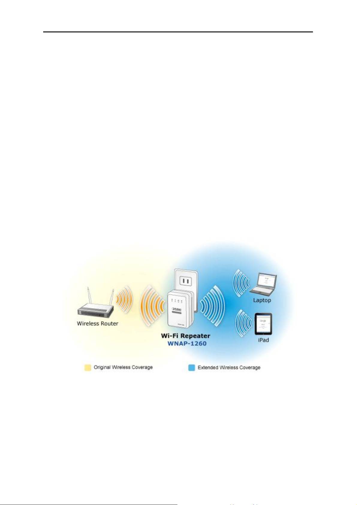
1.2. Product Description
WNAP-1260, a WiFi Repeater, is case-shaped, easy to carry, and easy to install. Its wireless
transmission rate is up to 300 Mbps. It is a high-performance and IEEE802.11b/g/n-compatible network
access device that can provide reliable and convenient network access service for individual users and
SOHO (Small Office, Home Office). It features Web-based GUI, allowing users to easily modify
settings to connect the device to ISP (Internet Service Provider) and conveniently perform upgrade
using the WEB page.
Figure 1-1
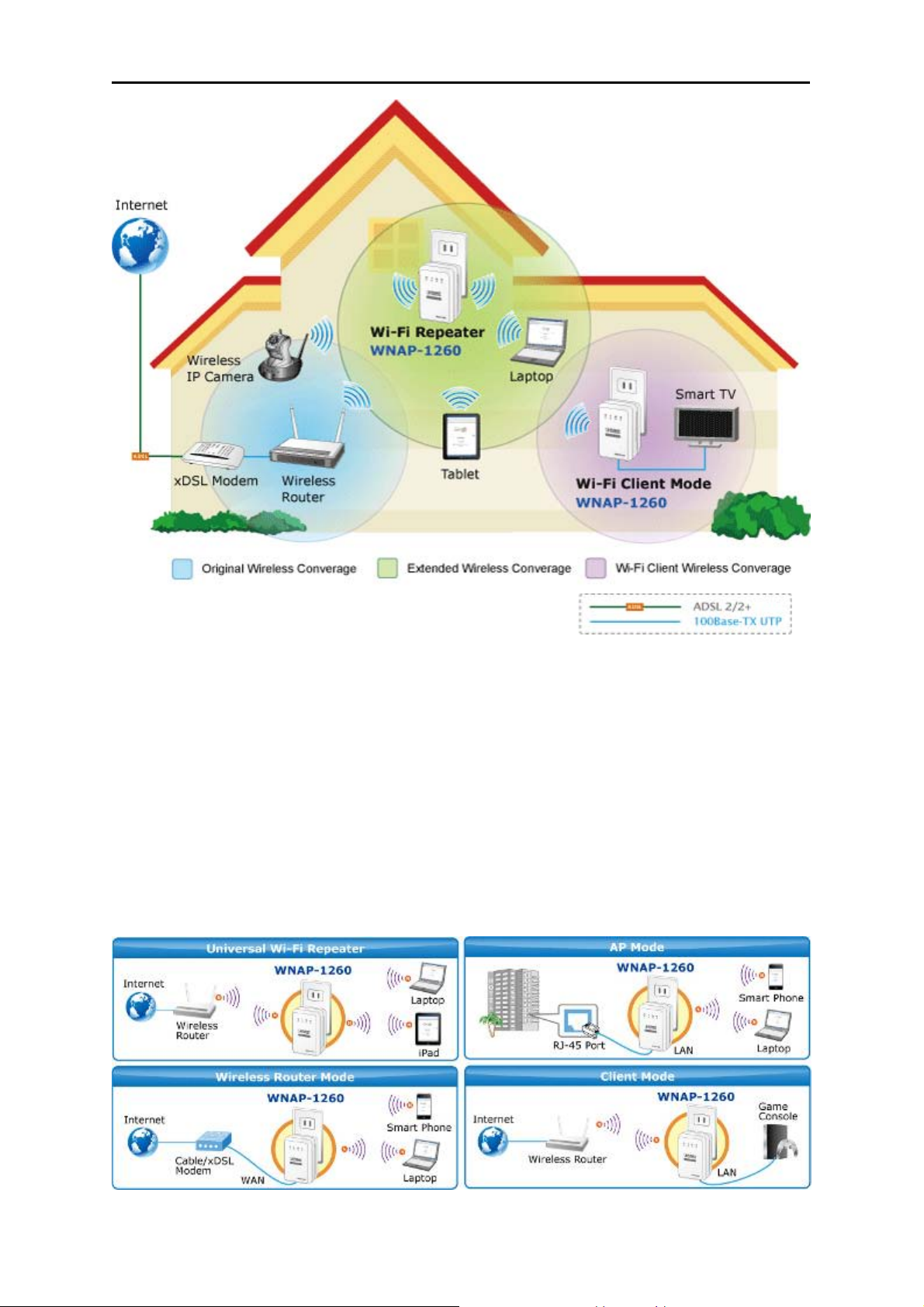
In addition, WNAP-1260 has a three-way switch on the side panel that enables users to change the
device’s working mode among AP, Repeater, and Client. In the AP mode, the device functions as a
wireless router to achieve wireless connection for the wired LAN. In the Repeater mode, the device
provides the URM (Universal Repeater Mode) function for users to expand wireless coverage of the
existing AP in a quick and easy way. In the Client mode, the device functions as a wireless network
adapter but it can provide a better transmission and connection performance.
-1-
Page 10
User’s Manual of WNAP-1260
Figure 1-2
Multiple Wireless Network Technologies for Greater Access
PLANET Wall Plug Universal WiFi Repeater, the WNAP-1260 features 802.11n radio with 2T2R
antenna technology compliant with 802.11b/g/n standards. Compared with general wireless routers,
the WNAP-1260 offers more powerful and flexible capability for business demands to access Internet
with true mobility and range extension of wireless network.
More Flexibility and Mobility
With the tiny-sized and wall plug design, the WNAP-1260 is easy to plug to wall outlet for wireless
access in any place. It can operate in various environments with the hardware switch modes including
AP, Repeater, and Client, which helps to immediately set up a wireless network without software
configuration. The wall plug design and operation flexibility make the WNAP-1260 suitable for range
extending.
Figure 1-3
-2-
Page 11

User’s Manual of WNAP-1260
One-touch Secure WiFi Extension
In order to simplify security settings for home and SOHO network, the WNAP-1260 supports Wi-Fi
Protected Setup (WPS) with configuration in PBC and PIN type. Just push the WPS button or key in
the PIN code, the secure connection between the WNAP-1260 and the Access Point can be built
immediately, which offers users a convenient and fast method to extend a secure wireless network.
Figure 1-4
Wide Range of Wireless Security Support
To secure the wireless communication, the WNAP-1260 supports most up-to-date encryptions
including WPA/WPA2-PSK with TKIP/AES.
the WNAP-1260 enhances security and management features such as multiple SSID support. It can
create up to 5 virtual standalone AP with 5 different SSID according to individual security levels and
encryption scheme of various wireless devices.
Made to fulfill enterprise and various applications demand,
Internet Broadband Sharing
PLANET Wall Plug Universal WiFi Repeater, WNAP-1260, provides home and SOHO users a reliable
and cost effective wireless solution by featuring WAN Internet access and high speed IEEE 802.11n
wireless transmission. The WNAP-1260 is equipped with one LAN/WAN port for connection to local
network or for wired cable / xDSL service connection. The WNAP-1260 provides more flexible and
easier way for users to share an instant wireless network service via range extension wherever at
Home, Hotspot, or in public places like transportation, outdoor events, and etc.
Advanced Firewall Security
In the Router mode, the WNAP-1260 supports NAT functions and allows multiple users to access
Internet via only one single legal IP. It provides Port Forwarding and DMZ for LAN PC to act as an
application server. Furthermore, the advanced firewall by the WNAP-1260 can protect your Intranet
clients from unauthorized accesses and various DoS attacks from the Internet. In aspect of the firewall,
the WNAP-1260 provides IP/ MAC/ Port/ URL filtering, and prevents possible hackers attack.
Easy Setup Anytime Anywhere
The WNAP-1260 provides a total solution for home and business users. With the High Speed 802.11n
wireless technology, the WNAP-1260 is easy to integrate the wireless devices with existing wired
network.
-3-
Page 12
User’s Manual of WNAP-1260
Figure 1-5
-4-
Page 13

1.3. Product Features
Industrial Compliant Wireless LAN & LAN
Compliant with IEEE 802.11n wireless technology capable of up to 300Mbps data rate
Backward compatible with 802.11b/g standard
Equipped with 10/100Mbps RJ-45 Ports for LAN/ WAN, Auto MDI/ MDI-X supported
Fixed-network Broadband Router
Supported connection types: Dynamic IP/ Static IP / PPPoE / PPTP / L2TP
Support Static Routing, IGMP Proxy
Support multiple sessions SIP ALG, IPSec, L2TP and PPTP VPN pass-through
Support DMZ, Port Forwarding and Port Triggering for various networking applications
Support DHCP Server, UPnP, Planet Dynamic DNS
User’s Manual of WNAP-1260
Wireless Network Range Extender
Multiple Wireless Modes: AP, WDS, Repeater, Universal Repeater, Client
Support Multiple SSID to allow users to access different networks through a single AP
Support WMM (Wi-Fi Multimedia), Wireless QoS
Support IAPP (Inter Access Point Protocol), Wireless Roaming
Secure Network Connection
Advanced security: 64/128-bit WEP, WPA/WPA2, WPA-PSK/WPA2-PSK(TKIP/AES)
Built-in NAT firewall features, with SPI function to protect against DoS attacks.
Support IP/ MAC/ URL/ DNS Filtering
Easy Installation & Management
Web-based UI and Quick Setup Wizard for easy configuration
Remote Management allows configuration from a remote site
System status monitoring includes DHCP Client and Associated Client list
Flexible Usage & Compact Design
Built-in Power Supply & Wall-Plug design
Hardware switchable operation modes: AP / Repeater / Client
Easy Sync by One-touch Wi-Fi Protected Setup (WPS)
-5-
Page 14

1.4. Product Specification
User’s Manual of WNAP-1260
Product
WNAP-1260
300Mbps 802.11n Wall Plug Universal WiFi Repeater
Hardware Specification
Interface
Antenna
LAN/WAN 1 x 10/100Mbps Auto MDI/MDI-X RJ45 port
Gain: 2 x Internal 2dBi Antenna
Orientation: Horizontal and Vertical
Mode Selection Switch (AP / Repeater / Client)
Button/Switch
WPS Button
Reset button
*Push about 3~6 seconds to reset to factory default settings
LED Indicators
Power
Consumption
Material
Dimension
Weight
PWR, WPS, Ethernet, WLAN
On-state: 2.1W
Low power state: 1.5W
Plastic
75 x 55 x 40 mm (L x W x H)
80g (gross weight)
Wireless interface Specification
Standard Compliance with IEEE 802.11b/g/n
Frequency Band 2.4~2.4835GHz
Extend Frequency DSSS
Modulation Type
DBPSK, DQPSK, QPSK, CCK and OFDM (BPSK/QPSK/16-QAM/
64-QAM)
11n (40MHz): 270/243/216/162/108/81/54/27Mbps
135/121.5/108/81/54/40.5/27/13.5Mbps (Dynamic)
Data Transmission
Rates
11n (20MHz): 130/117/104/78/52/39/26/13Mbps
65/58.5/52/39/26/19.5/13/6.5Mbps (Dynamic)
11g: 54/48/36/24/18/12/9/6Mbps (Dynamic)
11b: 11/5.5/2/1Mbps (Dynamic)
Transmission
Distance
Indoor up to 100m
outdoor up to 300m (it is limited to the environment)
America/ FCC: 2.412~2.462GHz (11 Channels)
Channel
Europe/ ETSI: 2.412~2.472GHz (13 Channels)
Japan/ TELEC: 2.412~2.484GHz (14 Channels)
Channel Width 20/ 40MHz
11b: 17±1.5dBm
Max. RF Power
11g: 14±1.5dBm
11n (20MHz): 14±1.5dBm
11n (40MHz): 14±1.5dBm
Receive Sensitivity
11b: -92dBm @ 1Mbps; -85dBm @ 11Mbps, PER < 8%
11g: -88dBm @ 6Mbps; -73dBm @ 54Mbps, PER <10%
11n: -90dBm @ MCS8; -70dBm @ MCS15, PER <10%
-6-
Page 15

Software Features
Operation Mode
User’s Manual of WNAP-1260
AP/Router
Repeater
Client
(Switchable by H/W)
Wireless Mode
Encryption Security
Wireless Security
Wireless Advanced
Max. Clients
Internet Connection
Type
AP, Client, WDS PTP, WDS PTMP, Repeater (WDS+AP), Universal
Repeater (AP+Client)
WEP (64/128-bit) encryption security
WPA / WPA2 (TKIP/AES)
WPA-PSK / WPA2-PSK (TKIP/AES)
Provide wireless LAN ACL (Access Control List) filtering
Wireless MAC address filtering up to 16 entries
Support WPS (Wi-Fi Protected Setup)
Enable/Disable SSID Broadcast
WMM(Wi-Fi Multimedia): 802.11e Wireless QoS
Multiple SSID: up to 4
Wireless Isolation: Enable it to isolate each connected wireless clients, to
let them cannot access mutually.
IAPP(Inter Access Point Protocol): 802.11f Wireless Roaming
Provide Wireless Statistics
Wire: 253
Wireless: 32
Shares data and Internet access for users, supporting following internet
access:
Dynamic IP
Static IP
PPPoE
PPTP
L2TP
NAT firewall with SPI (Stateful Packet Inspection)
Built-in NAT server supporting Port Forwarding, Port Triggering, and DMZ
Firewall
Built-in firewall with IP address/ MAC address/ Port/ URL filtering
Support ICMP-FLOOD, UDP-FLOOD, TCP-SYN-FLOOD filter, DoS
protection
Routing Protocol Static Routing
VPN Pass-through SIP ALG, PPTP, L2TP, IPSec
Built-in DHCP server supporting static IP address distributing
LAN
Support UPnP, Dynamic DNS
Support IGMP Proxy
Web-based (HTTP) management interface
System
Management
SNTP time synchronize
Easy firmware upgrade
Standards Conformance
IEEE Standards IEEE 802.11n (2T2R, up to 300Mbps)
-7-
Page 16

IEEE 802.11g
IEEE 802.11b
IEEE 802.11i
IEEE 802.3 10Base-T
IEEE 802.3u 100Base-TX
IEEE 802.3x Flow Control
User’s Manual of WNAP-1260
Others Protocols
and Standards
CSMA/CA, CSMA/CD, TCP/IP, DHCP, ICMP, NAT, PPPoE, SNTP
-8-
Page 17
2.1. Overview
User’s Manual of WNAP-1260
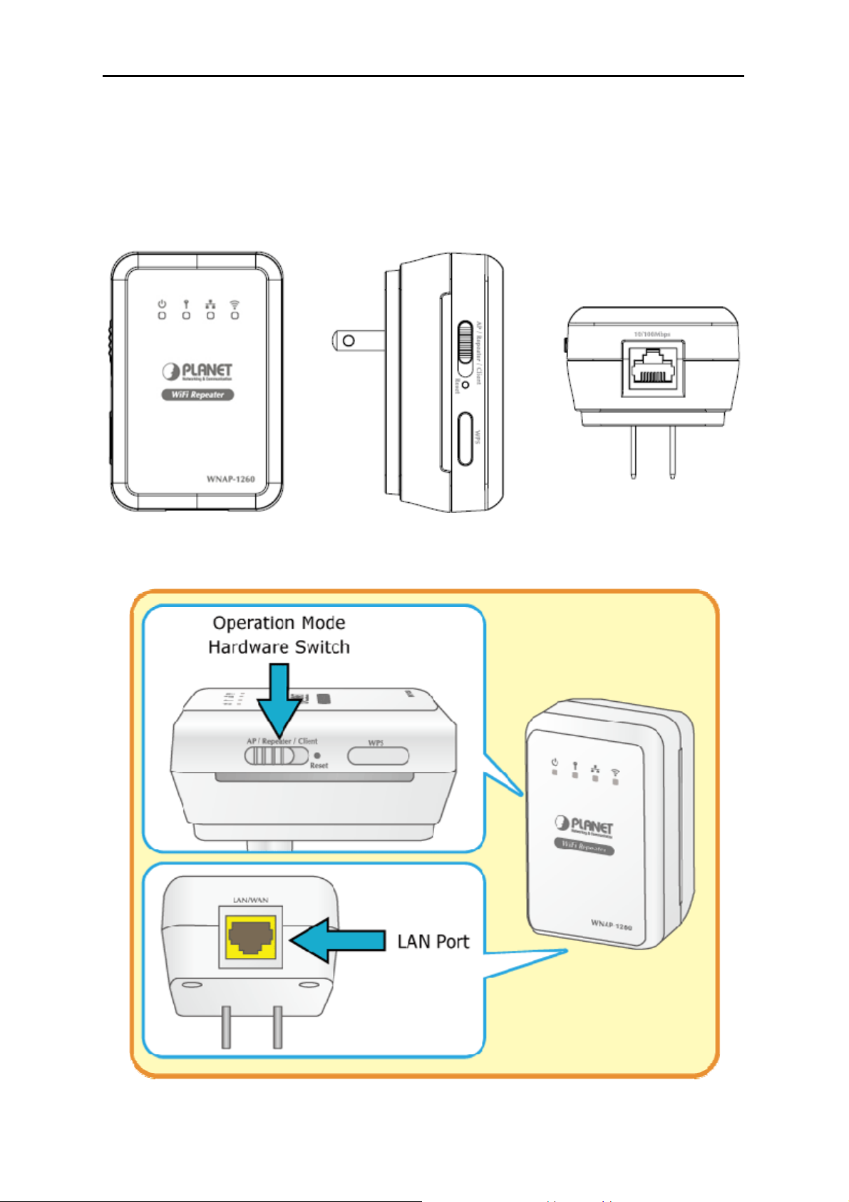
Chapter 2. Hardware Interface
Top View Left Side View Bottom Side View
Figure 2-1
Figure 2-2
-9-
Page 18
User’s Manual of WNAP-1260
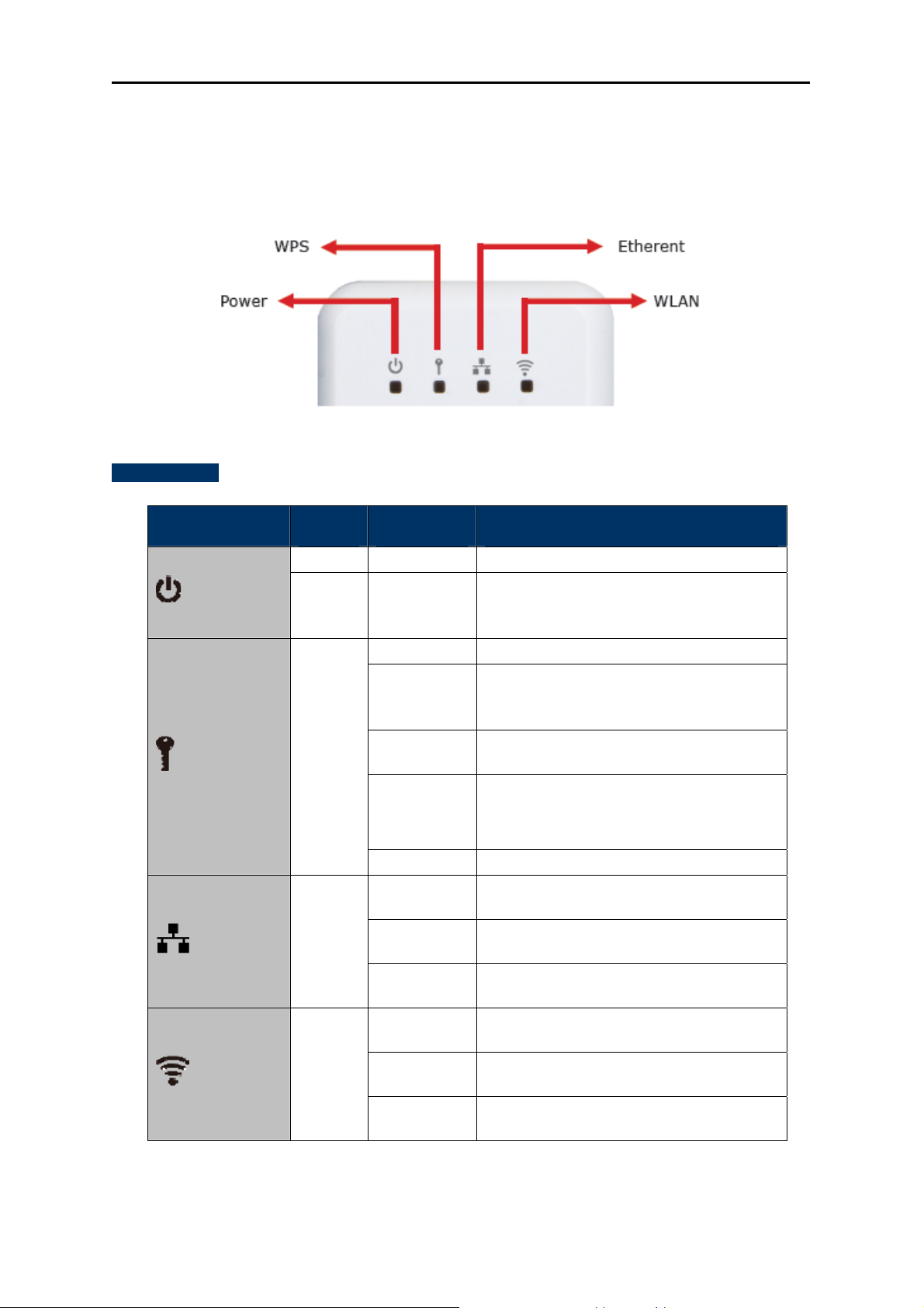
2.2. Front Panel and LED Indications
The LEDs on the top panel indicate the instant status of System power, WPS, Wireless data activity,
Ethernet port links and data activity, and help monitor and troubleshoot when needed. Figure 2-3
and Table 2-1 show the LED indications of the WNNAP-1260.
Figure 2-3
LED Definition
LED COLOR STATE FUNCTION
The device is working normally.
The system is in the process of
self-inspection or fails the self-inspection.
Power
Green On
Red On
Or it is in the process of software upgrade.
Off
The WPS session is down.
The WPS indicator keeps on for 5 minutes
On
after WPS (Wi-Fi Protected Setup)
connection succeeds.
A terminal is attempting to connect to the
WNAP-1260 through WPS but fails.
Multiple terminals are connecting to the
WNAP-1260 through WPS at the same
time. WPS sessions conflict.
The WPS session is up.
The Ethernet port is in the
non-communication state.
The Ethernet port is in the communication
state.
The Ethernet port is transmitting and
receiving data.
The WLAN connection is in the
non-communication state.
The WLAN connection is in the
communication state.
Data is being transmitted and received in
the WLAN.
WPS
Ethernet
WLAN
Green
Green
Green
Quick blink
Quick blink
with a certain
interval
Slow blink
Off
On
Blink
Off
On
Blink
Table 2-1
-10-
Page 19
User’s Manual of WNAP-1260
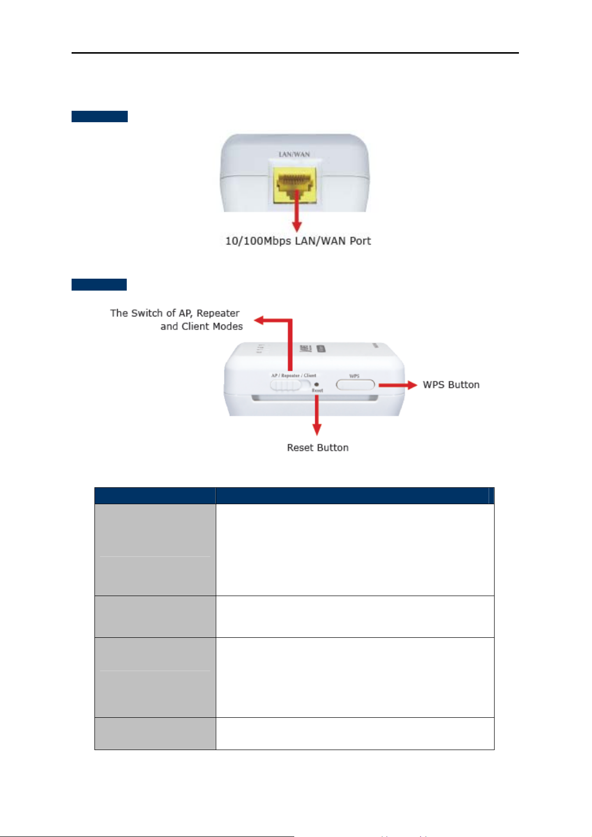
2.3. Rear/Side Panel and Interface Description
Rear Panel
Figure 2-4
Side Panel
Figure 2-5
Object Description
If WNAP-1260 is set to the Router mode, the interface is a
WAN interface which connects WNAP-1260 to WAN or uplink
WAN/LAN
network devices.
If WNAP-1260 is set to the Repeater/Client mode, the
interface is an LAN interface.
Press the Reset button gently for 3-6 seconds and then
Reset
release it. The system restores to the factory default settings.
It is used for setting WNAP-1260 to the AP, Repeater, or
Client mode.
AP/Repeater/Client
AP mode—including the Bridge and router modes
Repeater mode—to expand wireless network coverage
Client mode—equivalent to a wireless network adapter
WPS
For enabling WPS PBC mode. For more information, refer to
WPS descriptions for each mode.
Table 2-2
-11-
Page 20
User’s Manual of WNAP-1260
Chapter 3. Operation Mode Introduction
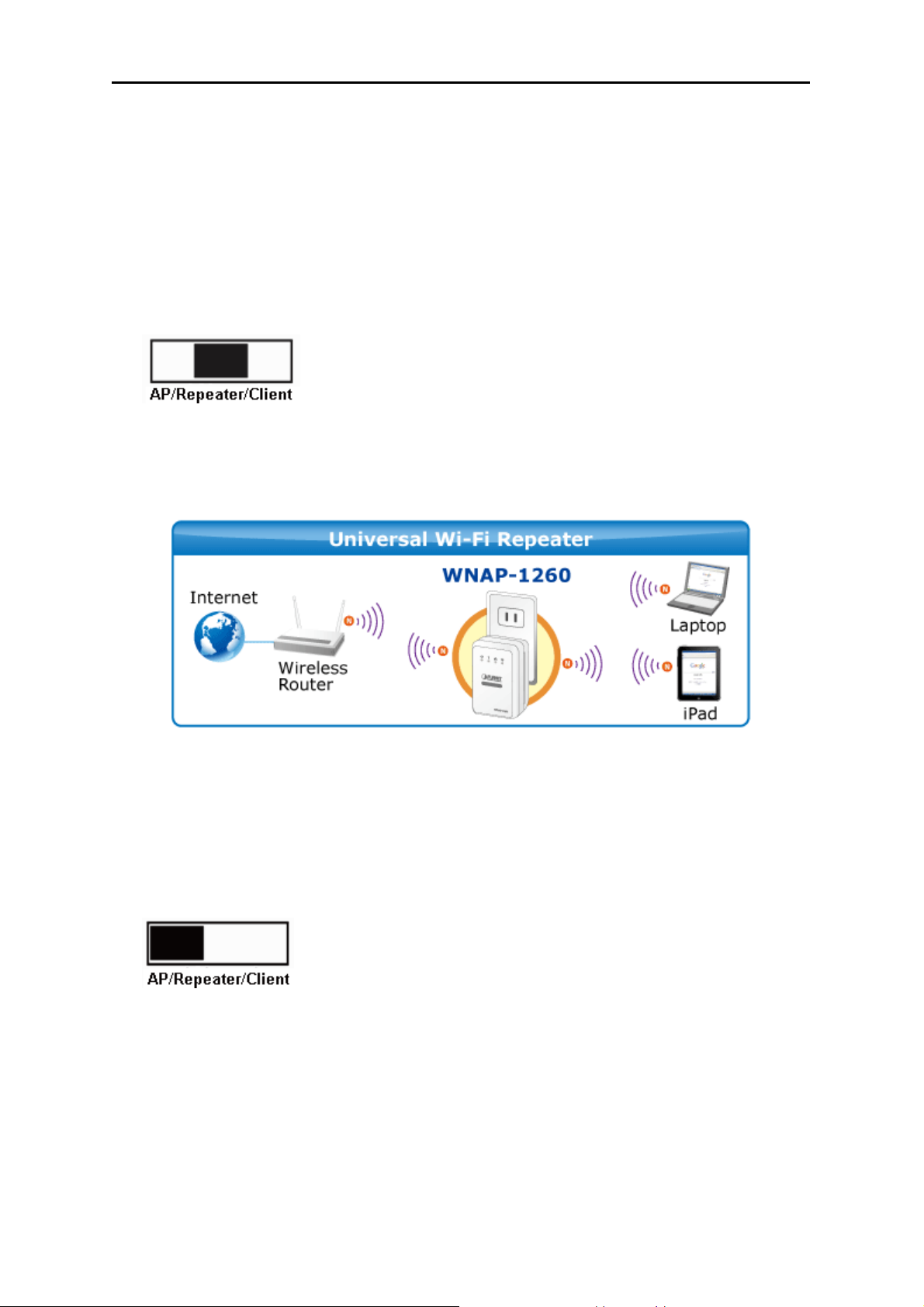
3.1. Wireless Universal Repeater/WDS Mode
In the Wireless Universal Repeater/WDS mode, WNAP-1260 expands wireless coverage of the
existing AP. Computers can connect to WNAP-1260 in either a wired or wireless way.
Operation Mode Switch - Repeater Mode
Typical Application
In the Wireless Universal Repeater/WDS mode, WNAP-1260 extends the coverage of AP, even if your
AP/Router doesn't have WDS function.
Figure 3-1
3.2. AP Mode
In the AP (Access Point) mode, WNAP-1260 works as a wireless router to achieve wireless connection
for the wired LAN.
Operation Mode Switch – AP Mode
Typical Application
In AP Mode, the NAT (Network Address Translation) function and DHCP server are both disabled, and
all wireless clients obtain the IP address from the network device connected with LAN port of the
WNAP-1260. They can certainly assign the IP address for themselves as well in the Control Panel of
Windows. The WNAP-1260 is supposed to bridge to the Ethernet directly by UTP cable.
-12-
Page 21
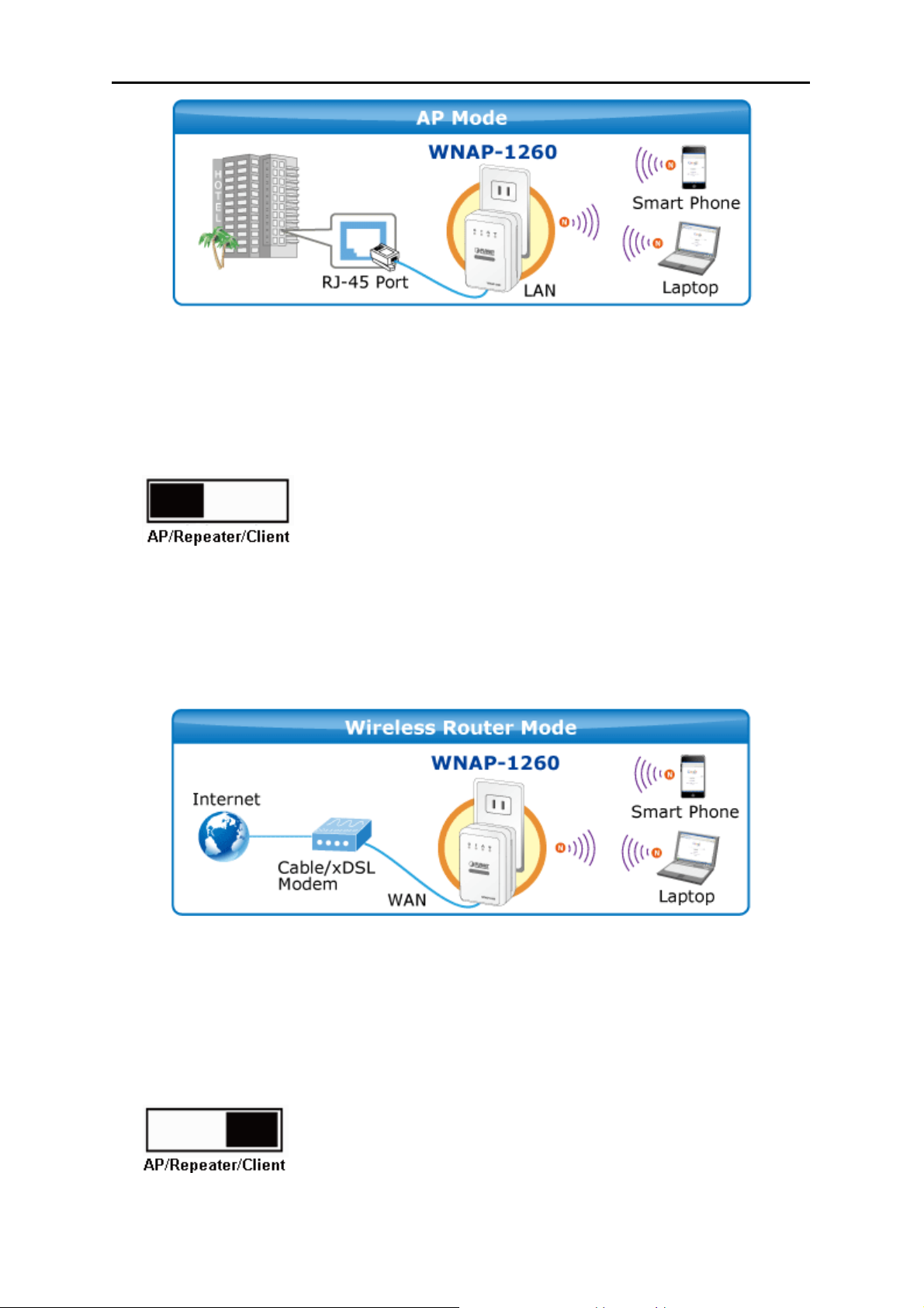
Figure 3-2
3.3. Router Mode
In the Router mode, WNAP-1260 works as a domestic gateway.
Operation Mode Switch – Router Mode
User’s Manual of WNAP-1260
Typical Application
In Router Mode, the NAT (Network Address Translation) function and DHCP server are both enabled,
and all wireless clients share the same public IP assigned by ISP through WAN port of the WNAP-1260.
The WNAP-1260 is supposed to connect with the Cable / xDSL Modem by UTP cable.
Figure 3-3
3.4. Client Mode
In the Client mode, WNAP-1260 provides Internet access for a set-top box or a computer with a
network adapter.
Operation Mode Switch – Client Mode
Typical Application
-13-
Page 22

User’s Manual of WNAP-1260
In Client Mode, the WNAP-1260 is supposed to act as a wireless station for the PC. Users can site
survey the available local AP and choose someone to connect with.
Figure 3-4
-14-
Page 23

User’s Manual of WNAP-1260
Chapter 4. Installation Guide
4.1. System Requirements
Before installing the device, please ensure that the following items are available:
PCs with a working Ethernet Adapter and an Ethernet cable with RJ-45 connectors
PC of subscribers running Windows 98/ME, NT4.0, 2000/XP, Windows Vista / Win 7, MAC
OS 9 or later, Linux, UNIX or other platform compatible with TCP/IP protocols
Above PC installed with WEB Browser
Broadband Internet Access Service (Cable / xDSL / Ethernet connection; for Router mode
only)
One Cable/xDSL Modem that has an RJ-45 connector (not necessary if the WNAP-1260 is
connected directly to the Ethernet.)
It is recommended to use Internet Explorer 7.0 or above to access the WNAP-1260.
4.2. Before You Begin
Before you install the device, please pay attention to the following items:
The Ethernet cables that are used to connect the device to a computer, hub, router, or switch
should be less than 100 meters.
Do not place this device on an uneven or unstable surface. Do not put this device on the
ground.
Keep the device clean. Prevent the device from direct sunlight. Avoid any metal in the
device.
Place the device in the center of the area to optimize the wireless coverage.
4.3. Operation Range
The operation range of WNAP-1260 WiFi repeater depends on the actual environment. The path and
effect of signal transmission vary with the deployment in a house or an office. For example, the outdoor
straight transmission distance for a certain device can reach 300 meters and the indoor transmission
distance can reach 100 meters.
4.4. Manual Network Setup - TCP/IP Configuration
The default IP address of the WNAP-1260 is 192.168.1.253, and the default Subnet Mask is
255.255.255.0. These values can be changed as you desire in the web UI of the WNAP-1260. In this
section, we use all the default values for description.
No matter you want to configure the WNAP-1260 via wired or wireless connection, the PC need to be
assigned an IP address first. Before you connect the local PC to the WNAP-1260 via wired or wireless
connection, please configure the IP address for your PC in the following two ways first.
Obtain an IP address automatically
Configure the IP address manually
-15-
Page 24
User’s Manual of WNAP-1260
The following sections will introduce how to install and configure the TCP/IP correctly in Windows 7.
First, make sure your Ethernet Adapter is working, and refer to the Ethernet adapter’s manual if
needed.
4.4.1. Obtain an IP Address Automatically
If you are sure the DHCP server of WNAP-1260 is enabled (the default setting of Router Mode), you
can set up the TCP/IP Protocol in "Obtain an IP address automatically" mode on your PC. And then
the WNAP-1260 built-in DHCP server will assign an IP address to the PC automatically.
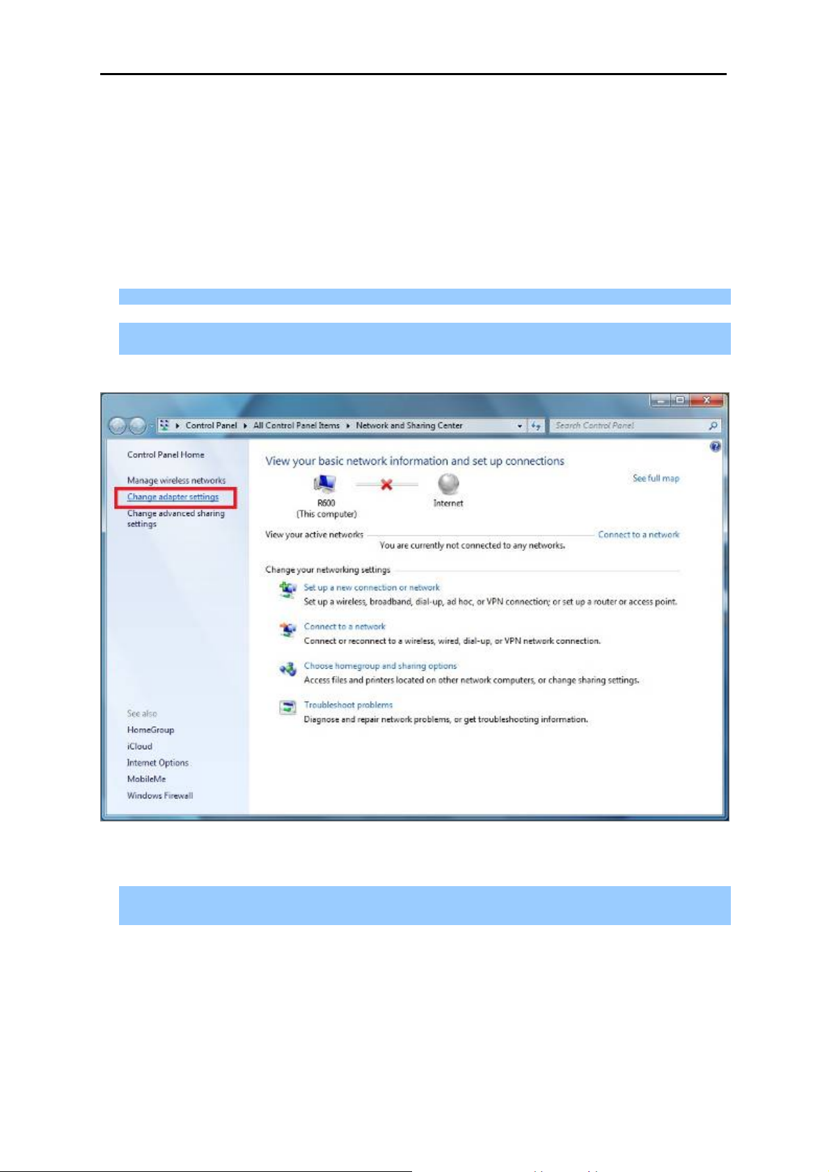
1) On the Windows taskbar, click the Start button, point to Control Panel, and then click it.
2) Under the Network and Internet icon, click on the View network status and tasks. And then
click Change adapter settings.
Figure 4-1
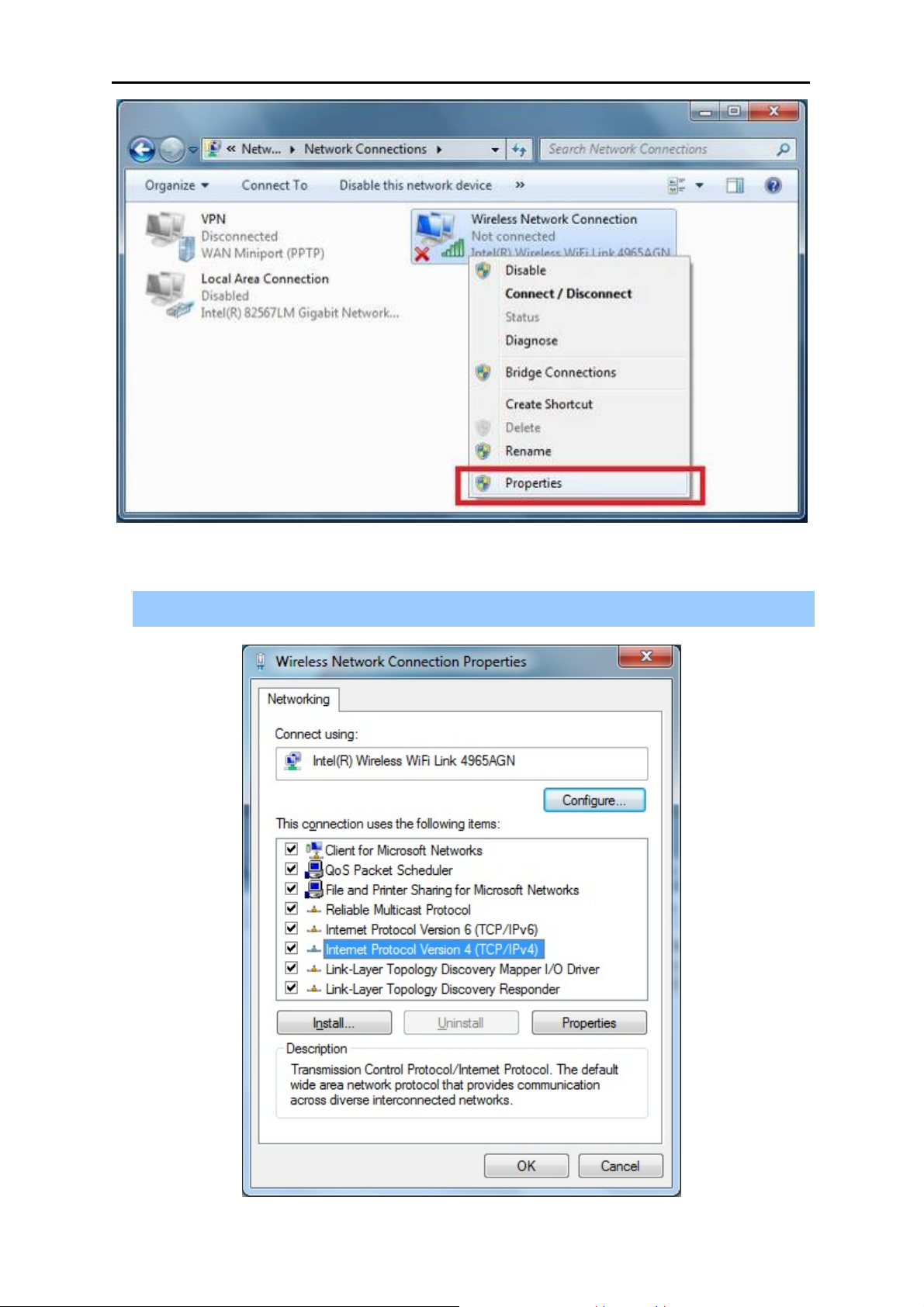
3) Right-click on the Wireless Network Connection, and select Properties in the appearing
window.
-16-
Page 25
User’s Manual of WNAP-1260
Figure 4-2
4) In the prompt window shown below, double click on the Internet Protocol Version 4
(TCP/IPv4).
Figure 4-3
-17-
Page 26
User’s Manual of WNAP-1260
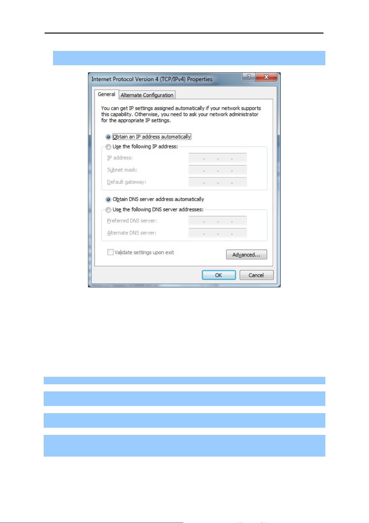
5) Choose Obtain an IP address automatically, and Obtain DNS server address automatically
as shown in the figure below. Then click OK to save your settings.
Figure 4-4
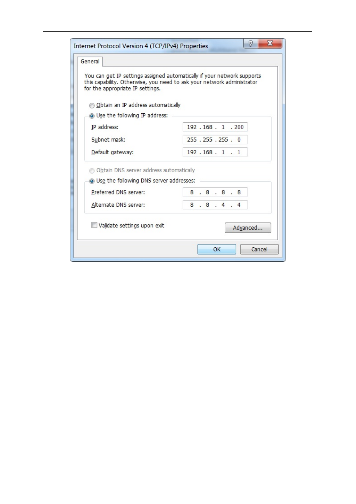
4.4.2. Configure the IP address manually
If you are sure the DHCP server of WNAP-1260 is disabled (the default setting of AP Mode and Client
Mode), you can configure the IP address manually. The IP address of your PC should be
192.168.1.xxx (the same subnet of the IP address of WNAP-1260, and "xxx" is any number from 1 to
254), Subnet Mask is 255.255.255.0, and the Gateway is 192.168.1.253 (The default IP address of
WNAP-1260)
1) Continue the settings from the last figure, select Use the following IP address radio button.
2) If the LAN IP address of the WNAP-1260 is 192.168.1.253, enter IP address 192.168.1.x (x is
from 1 to 254), and Subnet mask 255.255.255.0.
3) Enter the LAN IP address of the WNAP-1260 (the default IP is 192.168.1.253) into the Default
gateway field.
4) Select Use the following DNS server addresses radio button. In the Preferred DNS Server field,
you can enter the DNS server IP address provided by your local ISP. Then click OK to save your
settings.
-18-
Page 27
User’s Manual of WNAP-1260
Figure 4-5
-19-
Page 28
User’s Manual of WNAP-1260
4.5. Hardware Installation
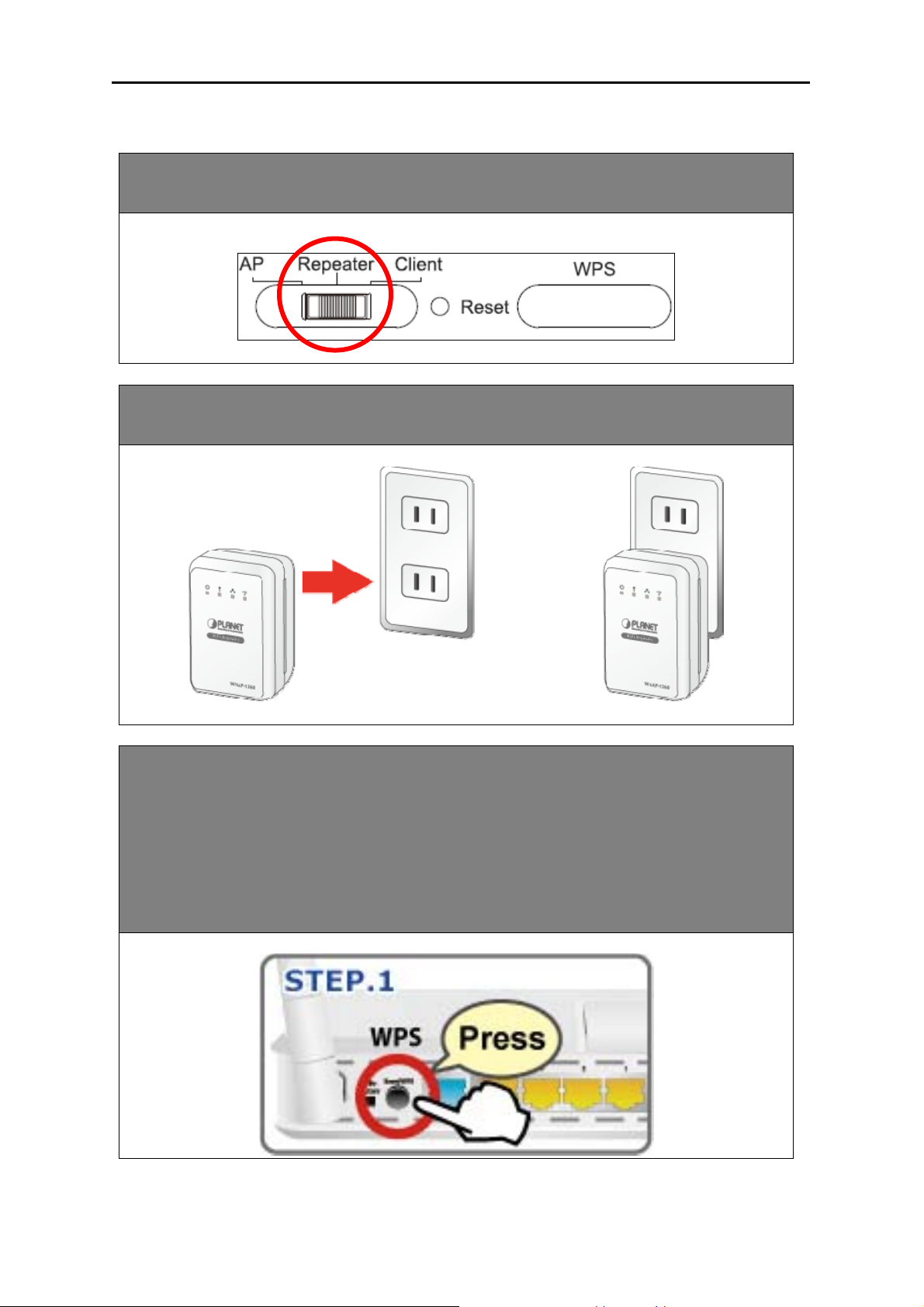
STEP 1: Make sure the operation mode by hardware switch is Repeater Mode (Default
Setting).
STEP 2: Plug WNAP-1260 into the wall outlet, and wait about 40 seconds for
WNAP-1260 to boot up.
STEP 3: Using WPS Button to establish connection with AP:
(1) In the existing Wireless Router or AP, push the WPS Button within 2 minutes.
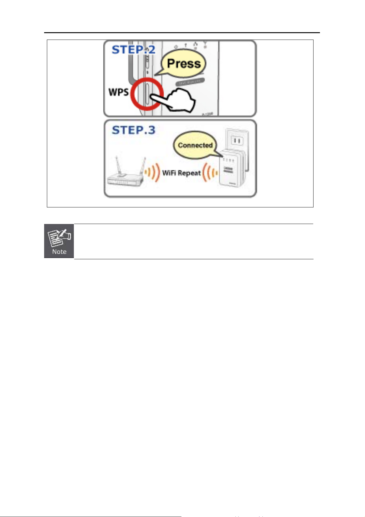
(2) In the WNAP-1260, push the WPS Button from the side panel within 2
minutes.
(3) Wait for the connection being established. If connection is successfully
established, the “WPS” LED will light for 5 minutes.
-20-
Page 29
User’s Manual of WNAP-1260
For the first time setup, you can move WNAP-1260 close to the access point you wish to
connect, after connection established, you can move WNAP-1260 to the place you wish
to use.
-21-
Page 30
User’s Manual of WNAP-1260
4.6. Starting Setup in Web UI
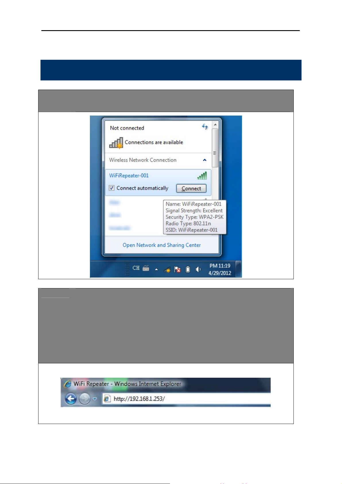
Default SSID: WiFiRepeater-001
*Default Wireless Security: None
STEP 1: Please use your PC to site survey the wireless signal of WNAP-1260, and connect
your PC with it wirelessly.
STEP 2: 1. Assign a static IP address to your PC which should be in the same network
segment with the WNAP-1260. You may choose from 192.168.1.2 to
192.168.1.254, except the default IP address “192.168.1.253” of WNAP-1260.
2. Open the web browser on your PC, key in the IP address (http://192.168.1.253)
of the WNAP-1260 in the address bar, and then press enter.
3. The default User name and Password are both “admin”. Enter them and then
click OK.
-22-
Page 31

Default IP Address: 192.168.1.253
Default Username: admin
Default Password: admin
Default SSID: WiFiRepeater-001
User’s Manual of WNAP-1260
STEP 3: When you have successfully logged in, select “Setup wizard”. You will then be able
to select one of two options, choose “Wireless Universal repeater mode” and click
next to continue.
STEP 4: All wireless access points nearby will be displayed on the list. Select it and click
‘Next’ button to continue.
STEP 5: You’ll be prompted to input Uplink Wireless Router/AP’s wireless security key, input it
in ‘KEY’ field and click ‘Next’ to continue.
-23-
Page 32

User’s Manual of WNAP-1260
STEP 6: WNAP-1260 provides the wireless roaming function if you select “Synchronize
Wireless Universal Repeater's And Uplink AP's SSID And Security Options”.
Click Finish. Then, the client can communicate with the selected network.
You have already finished the wireless range extension configuration of the WNAP-1260. Now you can use your
iPhone, iPad, laptop, and any other Wi-Fi devices to connect with it wirelessly and start to surf the Internet.
If you change the setting of wireless universal repeater through wireless connection, the wireless
clients connecting to your WNAP-1260 need connect to WNAP-1260 with new SSID and security
options again.
The next chapter will introduce the functions of the web UI.
-24-
Page 33

User’s Manual of WNAP-1260
Chapter 5. Quick Mode Configuration
Mode
Repeater
AP
Client
Mode Available In
the Web
Wireless Universal
Repeater (default)
WDS
Bridge (default) No Disable Ethernet cable /Wireless
Router
Client (default) 192.168.1.253 No Disable Ethernet cable only
LAN1 (Management
IP Address)
192.168.1.253
192.168.1.253
LAN2
(DHCP)
Yes
No
No Enable Wireless only
DHCP
Server
Disable Ethernet cable /Wireless
Way of connecting to PC
Table 4.1 IP information of AP/Repeater/Client modes of WNAP1260
Step 1 Set the three-way switch on the case of WNAP-1260 to the mode you want.
Step 2 Run the Internet Explorer (IE). Enter the management IP address of 192.168.1.253 and press
Enter. In the login window that is displayed, enter the user name and password (both admin),
and click Login.
Figure 5-1
Step 3 Configure parameters for the mode you selected.
Terminal devices can access the network through WNAP-1260 after you finish configuration by
following procedures in the sections below.
5.1. Repeater Mode Configuration
Step 1 Set the three-way switch on the side panel to Repeater after WNAP-1260 is powered on. Log
in to the configuration page after the system is started.
-25-
Page 34

User’s Manual of WNAP-1260
Step 2 Click Setup Wizard in the navigation bar on the left pane of the page. Select Wireless
Universal Repeater Mode and click Next.
Figure 5-2
Step 3 Click Site Survey to search for the wireless network you want to connect. Select a desired
network. Click Next.
Figure 5-3
Step 4 Configure the repeater with the same security option as its uplink network. (The following
figure takes the security option of WPA2-PSK[AES] as an example.) Set the encryption
password and note it down. Click Next.
Figure 5-4
-26-
Page 35

User’s Manual of WNAP-1260
Step 5 WNAP-1260 provides the wireless roaming function if you select Synchronize Wireless
Universal Repeater's And Uplink AP's SSID And Security Options. Otherwise, manually
configure the SSID and security options for the repeater. Click Finish to complete setup
wizard.
Figure 5-5
5.2. WDS Mode Configuration
5.2.1. Repeater Configuration in the WDS Mode
Step 1 Set the three-way switch on the side panel to Repeater after WNAP-1260 is powered on.
Log in to the configuration page after the system is started.
Step 2 Click Setup Wizard in the navigation bar on the left pane of the page. Select WDS Mode and
click Next. (Note: The WDS function cannot be used if the channel is set to Auto) Manually set
all WDS devices to the same channel.
Figure 5-6
-27-
Page 36

User’s Manual of WNAP-1260
Step 3 Set the IP address of the LAN port of the repeater and enter the MAC address of the basic
station. Click Next.
Figure 5-7
Step 4 Set the SSID, channel, and security encryption for the repeater. The channel cannot be set to
Auto. It is recommended to configure the repeater with the same security option as its base
station. Set the encryption password and note it down. Click Finish to complete the settings.
Figure 5-8
5.2.2. Central Base Station Configuration in the WDS Mode
Step 1 Set WNAP-1260 to the Router mode. (Set the three-way switch on the side panel to AP)
Step 2 Click Mode Settings and select Router Mode. (The default mode is Bridge Mode.)
Step 3 Choose Wireless Settings > WDS Function, select Enable WDS Function
Step 4 Enter the MAC address of the Repeater
-28-
Page 37

User’s Manual of WNAP-1260
Figure 5-9
One basic station can connect to a maximum of 4 repeaters
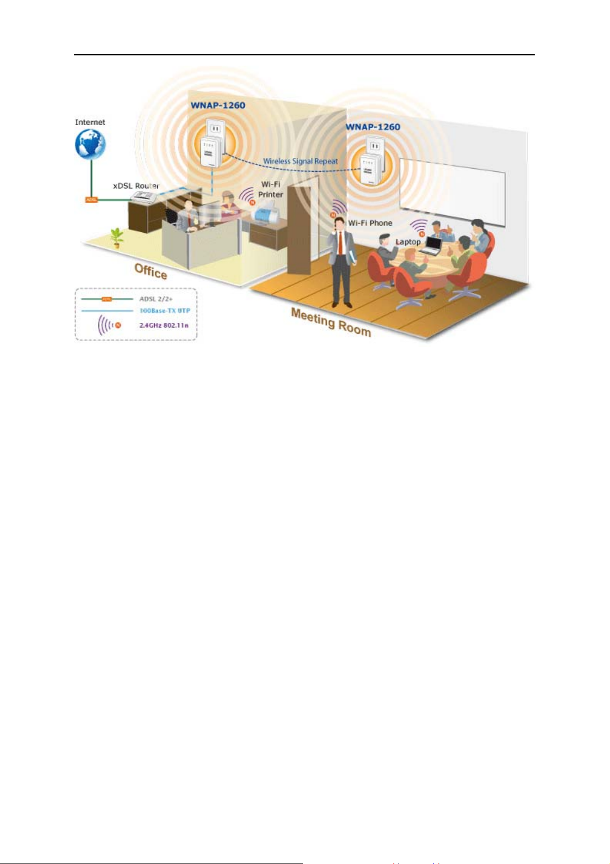
5.2.3. WDS Application
The following figure shows a wireless network for Humans Resource Department (marked as A in the
figure), Finance Department (marked as B), and Marketing Department (marked as C) in an enterprise.
If the three departments share one wireless router, signals searched by computers may be rather weak
or even no signals are available. However, if each of the three departments uses a wireless router, we
can use WDS to connect the three routers to provide perfect wireless coverage for the whole areas.
Figure 5-10
Configure the three routers in this way:
Wireless router B functions as the wireless basic station; wireless routers A and C connect to wireless
router B by using WDS.
(1) Configuring wireless router B as the wireless basic station
Step 1 Log in to the Web management page of wireless router B. Choose Wireless Settings >
Wireless Basic Settings and set the SSID, channel, and wireless encryption
-29-
Page 38

User’s Manual of WNAP-1260
information. Write down the SSID, channel, and wireless encryption information that are
required when you are configuring wirelss router A and C.
Step 2 Choose Wireless Settings > WDS Function and enable the WDS function. Enter MAC
addresses of repeaters (that is, wireless routers A and C in this example). Click Apply to
save the settings.
(2) Configuring wireless router A
Do as follows to establish WDS connection between wireless routers A and B:
Step 1 Set wireless router A with the same channel and encryption information as wireless
router B.
Step 2 Choose Wireless Settings > WDS Function and enable the WDS function. Set the IP
address of wireless router B different from that of wireless router B to avoid IP address
conflict (for example, change the IP address to 192.168.100.20 in the LAN Interface
Settings page and log in to the Web management page again).
Step 3 Enter the MAC address of the wireless basic station.
Step 4 Click Apply to save the settings.
Then, WDS connection is established between wireless routers A and B.
(3) Configuring wireless router C
Configure wireless router C in the same way as wireless router A. Note that the IP address of the
LAN interface must be changed to an IP address that does not conflict with IP addresses of
existing computers or devices in the network.
5.3. Bridge Mode Configuration
Step 1 Set the three-way switch on the side panel to AP after WNAP-1260 is powered on. Log in to
the configuration page after the system is started.
Step 2 Click Setup Wizard in the navigation bar on the left pane of the page. Set the SSID and
encryption password and note them down. Click Finish to complete the settings.
-30-
Page 39

User’s Manual of WNAP-1260
Figure 5-11
-31-
Page 40

User’s Manual of WNAP-1260
5.4. Router Mode Configuration
Step 1 Set the three-way switch on the side panel to AP after WNAP-1260 is powered on. Log in to
the configuration page after the system is started.
Step 2 Click Mode Settings and select Router Mode. (The default mode is Bridge Mode.)
Step 3 Connect your PC to WNAP-1260 using a wireless network adapter after WNAP-1260 is
restarted successfully. Log in to the configuration page. Click Setup Wizard in the navigation
bar on the left pane of the page. Select Yes and click Next. WNAP-1260 will automatically
detect the broadband type.
Step 4 WNAP-1260 can detect three types of broadband: DHCP, Static IP, and PPPoE. Perform
configurations according to the broadband type you are using.
Parameter configuration for DHCP
Parameter configuration for static IP
Figure 5-12
-32-
Page 41

Parameter configuration for PPPoE
User’s Manual of WNAP-1260
Figure 5-13
Figure 5-14
Step 5 Click Next. Set the SSID and password and note them down. Click Finish to complete the
settings.
Figure 5-15
-33-
Page 42

User’s Manual of WNAP-1260
5.5. Client Mode Configuration
Step 1 Set the three-way switch on the side panel to Client after WNAP-1260 is powered on. Log in to
the configuration page after the system is started.
Step 2 Click Setup Wizard in the navigation bar on the left pane of the page. Click Site Survey to
search for the wireless network you want to connect.
Figure 5-16
Step 3 Enter encryption information of the selected wireless network. Click Next.
Figure 5-17
Step 4 Check Synchronize Wireless Universal Repeater's And Uplink AP's SSID And Security
Options if you want to sync the SSID & Security key. Click Finish to complete the settings.
-34-
Page 43

User’s Manual of WNAP-1260
Figure 5-18
-35-
Page 44

User’s Manual of WNAP-1260
Chapter 6. Web Configuration for the Wireless
Universal Repeater Mode
6.1. Running Status
Click Running Status and the extended navigation menu is shown as follows:
Click the submenu to enter a specific configuration page.
6.1.1. System Status
Choose Running Status > System Status and the System Status page is displayed.
Figure 6-1
In this page, you can view information about the current running status of WNAP-1260, including
system information, LAN port status, wireless client information, and wireless universal repeater status.
-36-
Page 45

User’s Manual of WNAP-1260
6.1.2. Clients List
Choose Running Status > Clients List and the Clients List page is displayed.
Figure 6-2
This page displays information of devices connected to WNAP-1260, including the IP address, device
name, and MAC address of each device.
6.2. Setup Wizard
For settings, refer to section 5.3. “Repeater Mode Configuration”.
6.3. Repeater Mode Setting
Click Repeater Mode Settings and the Repeater Mode Settings page is displayed. Select Wireless
Universal Repeater Mode.
Figure 6-3
-37-
Page 46

User’s Manual of WNAP-1260
6.4. Network Settings
Click Network Settings and the extended navigation menu is shown as follows:
Click a submenu to perform specific parameter configurations.
6.4.1. LAN Interface Settings
Choose Network Settings > LAN Interface Settings and the LAN Interface Settings page is
displayed.
Figure 6-4
You can modify the IP address and IP subnet mask of the LAN port as required.
If you change the default IP address, you must use the new IP address to log in to the Web
configuration page of the router and the default gateway of all hosts in the LAN must be
set to the new IP address for internet access. The subnet mask of all hosts in the LAN
must be the same as the subnet mask specified in the LAN Interface Settings page.
6.4.2. DHCP Server
Choose Network Settings > DHCP Server and the DHCP Server page is displayed.
DHCP refers to Dynamic Host Configuration Protocol. If Use Device as DHCP Service is selected,
WNAP-1260 automatically assigns IP addresses to comupters in the LAN. Users do not need to
configure TCP/IP protocol paramters such as the IP address, the subnet mask, the gateway, and the
DNS server information for computers connected to the router’s LAN.
-38-
Page 47

User’s Manual of WNAP-1260
Figure 6-5
Using the Router as a DHCP Server
Use Rou
ter as DHCP Server: If you select the Use Router as DHCP Server check box,
WNAP-1260 serves as a DHCP server to automatically assign IP addresses to computers
connected to it.
Starting IP Address/Ending IP Address: Set the starting and ending IP addresses to specify a
pool of IP addresses to be assigned by the DHCP server. After you set Starting IP
Address/Ending IP Address, hosts in the LAN obtain IP addresses that are in the range of the
starting and ending IP addresses.
DHCP Lease Time: The valid time for an IP address that is automatically assigned by the DHCP
server to a host. The DHCP server does not assign the IP address to other hosts within the
specified time.
Using Address Reservation
n you specify a reserved IP address for a computer in the LAN, the computer always receives the
Whe
same IP address each time it accesses the router’s DHCP server. Reserved IP addresses should be
assigned to computers or servers that require permanent IP settings.
Figure 6-6
To reserve an IP address:
Step 1 Click Add to enter the Address Reservation page.
Figure 6-7
-39-
Page 48

User’s Manual of WNAP-1260
Step 2 Select one item from Address Reservation Table, or enter the IP address in the IP Address
field to assign to the computer or server (Choose an IP address from the IP address pool that
you have specified, for example 192.168.100.x). Enter the MAC address and device name of
the computer or server.
Step 3 Click Add to add a new item into Address Reservation.
Step 4 Click Apply to save the settings.
6.5. Wireless Settings
Click Wireless Settings and the extended navigation menu is shown as follows:
Click a submenu to perform specific parameter configurations.
6.5.1. Wireless Universal Repeater
In universal repeater mode, WNAP-1260 acts as the AP and client simultaneously.
Choose Wireless Settings > Wireless Universal Repeater and the Wireless Universal Repeater
page is displayed.
Figure 6-8
SSID of Extended Interface: Set the SSID of the repeater.
Security Options: Set the security encryption mode for the repeater. It is recommended to
configure the repeater with the same encryption mode as that of its uplink AP.
After finishing settings, click Apply to save the settings.
-40-
Page 49

User’s Manual of WNAP-1260
6.5.2. WPS Setup
WPS refers to Wi-Fi Protected Setup.
You can use WPS to establish wireless connection in a quick and secure way if the uplink AP or
terminal (for example, the network adapter) has the WPS function. It is suggested to first configure
wireless encryption for the uplink AP. If you change the wireless encryption mode after having
establishing wireless connection using WPS, you must use WPS to establish wireless connection
again. Note that if the wireless client does not support WPS you must manually configure the wireless
client (such as SSID, security mode, and password) to make it have the same SSID and wireless
security settings as the router.
In the Repeater mode with WDS disabled, WNAP-1260 can perform WPS encrypted connection to
both the uplink AP and the downlink client device.
The following describes how to configure WPS for the Repeater mode.
Using the WPS Button
WPS connection to the uplink AP
In the Repeater mode with WDS disabled, press the WPS button on the side panel of
WNAP-1260 in 3 seconds and release it. And press the WPS button on the uplink AP. Then they
can start WPS session.
WPS connection to the downlink client device
In the Repeater mode with WDS disabled, press the WPS button on the side panel of
WNAP-1260 for 3-10 seconds and release it. And press the WPS button on the client device.
Then they can start WPS session.
The SSID, authentication and pre-shared key for WNAP-1260 will automatically change to
the same as those of its uplink AP after WNAP-1260 succeeds in connecting to the uplink
AP through the WPS button mode.
Using the Web Page
You can perform WPS settings using the Web page for configuration.
Choose Wireless Settings > WPS Setup to display the WPS Setup page.
-41-
Page 50

User’s Manual of WNAP-1260
Figure 6-9
- As an AP
You can perform WPS settings using the Web page for configuration.
Choose Wireless Settings > WPS Setup to display the WPS page.
PBC mode
Step 1 Select Push Button and click Start PBC. WPS encrypted connection starts.
Step 2 Press the WPS button on the network adapter or click the PBC button in the network
adapter configuration tool within 2 minutes to start WPS connection. After WPS
connection is established, the following page is displayed, indicating that the WPS
connection is completed.
PIN mode
Step 1 Select PIN, enter the PIN code of the network adapter (refer to the client of the network
adapter), and click Start PIN to start WPS connection.
Step 2 Click the PIN button on the network adapter within 2 minutes to start WPS connection.
After WPS connection is established, the following page is displayed, indicating that the
WPS connection is completed.
- As a client
You can perform WPS settings using the Web page for configuration.
Choose Wireless Settings > WPS to display the WPS page.
PBC mode
Step 1 Select Push Button and click Start PBC. WPS encrypted connection starts.
Step 2 Start the WPS PBC process. After WPS connection is established, the following page is
displayed, indicating that the WPS connection is completed.
PIN mode
Step 1 Select PIN, click Generate New PIN, and click Start PIN to start WPS connection.
-42-
Page 51

User’s Manual of WNAP-1260
Step 2 Start the WPS PBC process within 2 minutes to start WPS connection. After WPS
connection is established, the following page is displayed, indicating that the WPS
connection is completed.
6.5.3. Wireless Client Function
Choose Wireless Settings > Wireless Client Function and the Wireless Client Function page is
displayed.
Figure 6-10
Step 1 Click Site Survey to search for the wireless network you want to connect.
Step 2 Enter encryption information of the selected wireless network.
Step 3 Configure the client with the same security settings as the selected network. Click Next.
Figure 6-11
Step 4 WNAP-1260 provides the wireless roaming function if you select Synchronize Wireless
Universal Repeater's And Uplink AP's SSID And Security Options. Click Finish.
Then, the client can communicate with the selected network.
-43-
Page 52

Figure 6-12
User’s Manual of WNAP-1260
-44-
Page 53

User’s Manual of WNAP-1260
6.6. Management Function
Click Management Function and the extended navigation menu is shown as follows.
Click a submenu to perform specific parameter configurations.
6.6.1. Backup Settings
Choose Management Function > Backup Settings and the Backup Settings page is displayed.
Figure 6-13
In this page, you can export configuration information of the router to the computer in the form of XML
for later use, import a previously saved or a new configuration file, and restore the factory default
settings of the router.
Backup
Click Backup and save configuration information of the router as a local file.
Before saving your configuration file, change the administrator password to the default
(admin) in case you forget your password. Then change it again after you have saved the
configuration file. If you forget the password, you will need to reset the configuration to
factory defaults.
Restore
The Backup and Restore options in the Backup Settings page let you save and retrieve a file
containing your router’s configuration settings.
Click Browse… to select the configuration file restored in your computer and click Restore to load
the file to the router.
Erase
Under some circumstances (for example, if you move the router to a different network or if you
-45-
Page 54

User’s Manual of WNAP-1260
have forgotten the password) you might want to erase the configuration and restore the factory
default settings.
Click Erase to restore the factory default settings of the router. This operation has the same effect
as pressing the Reset button on the side panel for 3-6 seconds.
6.6.2. Reboot Device
Choose Management Function > Reboot Device and the Reboot Device page is displayed.
Figure 6-14
Click Reboot to reboot the router. After the router is rebooted, the system jumps to the login page.
6.6.3. Set Password
Choose Management Function > Set Password and the Set Password page is displayed.
Figure 6-15
In this page, you can change the password of the administrator and set the page timeout time.
For security, it is strongly recommended to change the default password of the
administrator. If you forget the password, you can restore the router to the default settings.
The default password is admin.
-46-
Page 55

User’s Manual of WNAP-1260
6.6.4. Upgrade
Choose Management Function > Upgrade and the Upgrade page is displayed.
Figure 6-16
Upgrade the software of the router in the following steps:
Step 1 Click Browse… to navigate to the latest software.
Step 2 Select the correct upgrade file. If you select Clear Config, the router restores to the
default settings after upgrade. If you do not select it, the current settings remain.
Step 3 Click Upload to start upgrade.
After the upgrade is completed, the router automatically reboots.
After the software upgrade, WNAP-1260 returns to the factory default settings. In case of
losing the previous configuration information, please save settings before updating the
software. Do not power off the device during upgrade.
-47-
Page 56

User’s Manual of WNAP-1260
Chapter 7. Web Configuration for the Bridge Mode
7.1. Bridge / AP Mode Topology
7.2. Hardware Setting
Set the three-way switch on the side panel to AP after WNAP-1260 is powered on.
7.3. Running Status
Log in to the configuration page after the system is started.
Click Running Status and the extended navigation menu is shown as follows:
Click the submenu to enter a specific configuration page.
7.3.1. System Status
Choose Running Status > System Status and the System Status page is displayed.
-48-
Page 57

User’s Manual of WNAP-1260
Figure 7-1
In this page, you can view information about the current running status of WNAP-1260, including
system information, LAN port status, and wireless network status.
7.3.2. Clients List
Choose Running Status > Clients List and the Clients List page is displayed.
Figure 7-2
This page displays information of computers connected to the router, including the IP adress, and MAC
address of each computer.
7.4. Setup Wizard
For settings, refer to section 5.3. “Bridge Mode Configuration”.
7.5. Mode Setting
Click Mode Settings and the Mode Settings page is displayed.
-49-
Page 58

User’s Manual of WNAP-1260
Figure 7-3
Bridge Mode: The interface on its case is an LAN interface. Users can connect WNAP-1260 and
the PC using an RJ45 cable or a wireless network card.
Router Mode: Computers can connect to WNAP-1260 in a wireless way only.
7.6. Network Settings
Click LAN Interface Settings and the extended navigation menu is shown as follows:
Click a submenu to perform specific parameter configurations.
7.6.1. LAN Interface Settings
Choose Network Settings > LAN Interface Settings and the LAN Interface Settings page is
displayed.
Figure 7-4
You can modify the IP address and IP subnet mask of the LAN port as required.
If you change the default IP address, you must use the new IP address to log in to
the Web configuration page of the router and the default gateway of all hosts in the
LAN must be set to the new IP address for internet access.
The subnet mask of all hosts in the LAN must be the same as the subnet mask
specified in the LAN Interface Settings page.
-50-
Page 59

User’s Manual of WNAP-1260
7.6.2. DHCP Server
Choose Network Settings > DHCP Server and the DHCP Server page is displayed.
DHCP refers to Dynamic Host Configuration Protocol. If Use Device as DHCP Service is selected,
WNAP-1260 automatically assigns IP addresses to comupters in the LAN. Users do not need to
configure TCP/IP protocol paramters such as the IP address, the subnet mask, the gateway, and the
DNS server information for computers connected to the router’s LAN.
Figure 7-5
Using the Router as a DHCP Server
Use Rou
ter as DHCP Server: If you select the Use Router as DHCP Server check box,
WNAP-1260 serves as a DHCP server to automatically assign IP addresses to computers
connected to it.
Starting IP Address/Ending IP Address: Set the starting and ending IP addresses to specify a
pool of IP addresses to be assigned by the DHCP server. After you set Starting IP
Address/Ending IP Address, hosts in the LAN obtain IP addresses that are in the range of the
starting and ending IP addresses.
DHCP Lease Time: The valid time for an IP address that is automatically assigned by the DHCP
server to a host. The DHCP server does not assign the IP address to other hosts within the
specified time.
Using Address Reservation
n you specify a reserved IP address for a computer in the LAN, the computer always receives the
Whe
same IP address each time it accesses the router’s DHCP server. Reserved IP addresses should be
assigned to computers or servers that require permanent IP settings.
To reserve an IP address:
Step 1 Click Add to enter the Address Reservation page.
-51-
Page 60

User’s Manual of WNAP-1260
Figure 7-6
Step 2 Select one item from Address Reservation Table, or enter the IP address in the IP Address
field to assign to the computer or server (Choose an IP address from the IP address pool that
you have specified, for example 192.168.1.x). Enter the MAC address and device name of the
computer or server.
Step 3 Click Add to add a new item into Address Reservation.
Step 4 Click Apply to save the settings.
-52-
Page 61

User’s Manual of WNAP-1260
7.7. Wireless Settings
Click Wireless Settings and the extended navigation menu is shown as follows:
Click a submenu to perform specific parameter configurations.
7.7.1. Wireless Basic Settings
Choose Wireless Settings > Wireless Basic Settings and the Wireless Basic Settings page is
displayed.
Object Description
Region:
Select the region where you are located.
If enabled, the router broadcasts its SSID in the wireless network.
Enable SSID
Broadcast:
Wireless clients can scan the SSID and access the wireless network
under the SSID.
If selected, wireless clients connected to the network of the same
Enable Wireless
Isolation:
Name (SSID):
SSID can access the Internet only, but cannot communicate with
each other.
Set the name for the wireless network. The SSID can contain up to
32 characters and can be letters, numerals, underlines, and any
Figure 7-7
-53-
Page 62

User’s Manual of WNAP-1260
combinations of them. The SSID is case-sensitive
Mode:
Select the wireless mode. Mixed 802.11b/g/n is recommended.
The channel for transmitting wireless signals. When you select Auto,
WNAP-1260 automatically selects the best channel from the
Channel:
available channels according to actual situations.
The default channel is Auto.
Band Width:
Max Transmission
Rate:
Security Options:
The bandwidth occupied for wireless signal transmission.
The maximum transmission rate of WNAP-1260.
Set the security encryption of the wireless network, to prevent
unauthorized access and listening.
Security Options
- None
Data encryption is not adopted and the network is not secure. Any stations can access the network.
This option is not recommended.
Figure 7-8
- WEP
Wired Equivalent Privacy. You can use WEP 64- or 128-bit encryption.
Figure 7-9
Object Description
Authentication
Type:
Select the authentication type that the system adopts.
Three authentication types are available: Automatic, Open, and
Shared keys.
Automatic:
-54-
Page 63

Encryption Type :
User’s Manual of WNAP-1260
If selected, the router uses an authentication type of Open or
Shared keys according to the request of the host.
Open:
If selected, hosts in the wireless network can pass the
authentication and connect to the wireless network without
using a password. However, the password is required if you
want to transmit data.
Shared keys:
If selected, hosts in the wireless network can pass
authentication only when the correct password is entered.
Otherwise, the hosts cannot connect to the wireless network.
The type of the key to be set. Hexadecimal and ASCII code are
available.
Hex: Valid characters for keys contain 0–9 and A–F.
ASCII: Valid characters for keys contain all characters of the
key board.
The encryption strength determines the length of the key.
Encryption
Strength:
If Encryption Strength is set to 64 bits, set the key to 10
hexadecimal digits or 5 ASCII characters.
If Encryption Strength is set to 128 bits, set the key to 26
hexadecimal digits or 13 ASCII characters.
Key 1/2/3/4:
Set the key based on the selected encryption type and encryption
strength.
- WPA-PSK[TKIP] or WPA2-PSK[TKIP]
WPA-PSK: Preshared key Wi-Fi protection access
WPA2-PSK: Preshared key Wi-Fi protection access version 2
TKIP: Temporal Key Integrity Protocol
Figure 7-10
Figure 7-11
PassPhrase: Enter 8-63 ASCII characters or 64 hexadecimal digits.
-55-
Page 64

The 802.11n mode does not support the TKIP algorithm.
- WPA-PSK[AES] or WPA2-PSK[AES]
WPA-PSK: Preshared key Wi-Fi protection access.
WPA2-PSK: Preshared key Wi-Fi protection access version 2.
AES: Advanced Encryption Standard
User’s Manual of WNAP-1260
Figure 7-12
PassPhrase: Enter 8-63 ASCII characters or 64 hexadecimal digits.
- WPA-PSK/WPA2-PSK+[TKIP]/[AES]
It allows the client to use either WPA-PSK[TKIP]/[AES] or WPA2-PSK[TKIP]/[AES].
Figure 7-13
PassPhrase: Enter 8-63 ASCII characters or 64 hexadecimal digits.
- After you complete configuring wireless settings for WNAP-1260, only hosts that
have the same wireless settings (for example, the SSID) as WNAP-1260 can
connect to it.
- If you configure security settings for WNAP-1260, hosts must have the same security
settings (for example, the password) as WNAP-1260 in order to connect to
WNAP-1260.
-56-
Page 65

User’s Manual of WNAP-1260
7.7.2. Multiple SSID
If you do not want visitors to know your wireless security key, you can use the Multiple SSID to allow
them to use your Internet without knowing your wireless connection password.
Choose Wireless Settings > Multiple SSID and the Multiple SSID page is displayed.
Figure 7-14
Object Description
Brief description of the created Multiple SSID. You can create up to
four Multiple SSIDs. A network profile contains the SSID and
Network Profiles:
encryption mode, whether to use the Multiple SSID, and whether to
broadcast SSID. You can click the radio button of a profile to view
detailed information or modify settings.
Enable Multiple
SSID:
Enable SSID
Broadcast:
If enabled, both you and visitors can connect to the network by using
the SSID of the Multiple SSID.
If enabled, WNAP-1260 broadcasts its SSID to all wireless stations.
If enabled, visitors using the SSID of a guest network can access not
Allow Guest to
access My Local
Network:
only the Internet but also the LAN of WNAP-1260, like users using
the primary SSID of the network. If disabled, visitors using the SSID
of a guest network cannot access the LAN of WNAP-1260.
If selected, wireless clients connected to the guest network of the
Enable Wireless
Isolation:
same SSID can access the Internet only, but cannot communicate
with each other.
Guest Wireless
Network Name
Set the name of the Multiple SSID.
(SSID):
Security Options:
Refer to security option descriptions in section “Wireless Basic
Setting
s”.
After finishing settings, click Apply to save the settings.
-57-
Page 66

User’s Manual of WNAP-1260
7.7.3. Wireless Advanced Settings
Choose Wireless Settings > Wireless Advanced Settings and the Wireless Advanced Settings
page is displayed.
Object Description
If you disable the wireless router radio, wireless devices cannot
Enable Wireless
Router Radio:
connect to the WNAP-1260 router. If you do not use your wireless
network for a period of time, you can clear this check box and
disable all wireless connectivity
Enable WMM (Wi-Fi
multi-media)
Settings:
WMM function can guarantee the packets with high- priority
messages being transmitted preferentially. It is strongly
recommended enabled
Set the threshold of fragmentation length. If the length of a packet
exceeds the set value, the packet is automatically fragmented into
Fragmentation
Length (256-2346):
several packets. The value of Fragmentation Length cannot be too
small because excessive packets reduce wireless network
performance. The default value is 2346.
DTIM (1-255):
Set the interval for sending DTIM frames
The beacon interval is the frequency of sending Beacon frames. Set
Beacon Interval
(20-1000):
the interval for sending Beacon frames. The unit is millisecond (ms).
The default value is 100 ms
Figure 7-15
-58-
Page 67

User’s Manual of WNAP-1260
MAX Clients (0-12):
CTS/RTS
Threshold (1-2347):
Preamble Mode:
Guard Interval:
Transmit Power
Control:
Set the maximum number of clients. 0 indicates the number of
connected clients is not limited
Set the CTS/RTS threshold. If the length of a packet is greater than
the specified RTS value, WNAP-1260 sends an RTS frame to the
destination station to negotiate. After receiving an RTS frame, the
wireless station responds with a Clear to Send (CTS) frame to
WNAP-1260, notifying that they can communicate with each other
A preamble (especially the 802.11b High Rate/DSSS PHY field; 56
digits synchronized field for short preamble) defines the length of the
CRC correction block for communication between wireless devices.
Short preamble should be applied in a network with intense traffics.
It helps improve the efficiency of a wireless network responding to
applications that have high requirement of real-time, such as
streaming video and voice-over-IP telephony.
Short GI:
The interval is 400 ns. When short GI is enabled, WNAP-1260
can receive and send short-frame-interval packets. This helps
improve the transmission rate of WNAP-1260.
Long GI:
The interval is 800 ns.
Set the transmit power of the wireless network. It is recommended to
use the default setting of 100%.
Restricting wireless access by MAC address
When a wireless card access list is configured and enabled, the router checks the MAC address of any
wireless device attempting a connection and allows only connections to computers identified on the
trusted computer list.
The MAC address is a network device’s unique 12-character physical address, containing the
hexadecimal characters 0–9, a–f, or A–F only. The MAC address is in the format of
XX:XX:XX:XX:XX:XX.
To restrict wireless access by MAC address:
Step 1 Click Setup Access List button in the Wireless Advanced Settings page to display the
Wireless Card Access List page.
-59-
Page 68

User’s Manual of WNAP-1260
Figure 7-16
Step 2 Click Add to add a wireless device to the wireless access control list. The Wireless Card
Access Setup page is displayed.
Figure 7-17
Step 3 If the computer you want appears in the Available Wireless Cards list, you can select the
radio button of that computer to obtain its MAC address. Otherwise, you can manually enter
a name and MAC address of the computer to be authorized. Generally, the MAC address is
labeled on the bottom of the wireless device.
Step 4 Click Add to add this wireless device to the wireless card access list. The page jumps to the
list page.
Step 5 Select Turn Access Control On. If selected, you can restrict PCs’ access to the wireless
network, only allowing specified PCs to access your network according to their MAC
addresses.
Step 6 Click Apply to save your Wireless Card Access List settings.
Now, only devices on this list can wirelessly connect to the WNAP-1260 router.
-60-
Page 69

User’s Manual of WNAP-1260
7.7.4. WPS Setup
WPS refers to Wi-Fi Protected Setup.
You can use WPS to establish wireless connection in a quick and secure way if the uplink AP or
terminal (for example, the network adapter) has the WPS function. It is suggested to first configure
wireless encryption for the uplink AP. If you change the wireless encryption mode after having
establishing wireless connection using WPS, you must use WPS to establish wireless connection
again. Note that if the wireless client does not support WPS you must manually configure the wireless
client (such as SSID, security mode, and password) to make it have the same SSID and wireless
security settings as the router.
The following describes how to configure WPS for the AP mode.
Using the WPS Button
In the AP mode with WDS disabled, press the WPS button on the side panel of WNAP-1260 and the
WPS button on the client device. WNAP-1260 can perform WPS encrypted connection to the downlink
client device.
Figure 7-18
Using the Web Page
You can perform WPS settings using the Web page for configuration.
Choose Wireless Settings > WPS Setup to display the WPS Setup page.
PBC mode
Step 1 Select Push Button and click Start PBC. WPS encrypted connection starts.
Figure 7-19
Step 2 Press the WPS button on the network adapter or click the PBC button in the network adapter
configuration tool within 2 minutes to start WPS connection.
-61-
Page 70

User’s Manual of WNAP-1260
Step 3 After WPS connection is established, the following page is displayed, indicating that the WPS
connection is completed.
Figure 7-20
PIN mode
Step 4 Select PIN, enter the PIN code of the network adapter (refer to the client of the network
adapter), and click Start PIN to start WPS connection.
Figure 7-21
Step 5 Click the PIN button on the network adapter within 2 minutes to start WPS connection.
Step 6 After WPS connection is established, the following page is displayed, indicating that the WPS
connection is completed.
-62-
Page 71

User’s Manual of WNAP-1260
Figure 7-22
7.8. Management Function
Click Management Function and the extended navigation menu is shown as follows.
Click a submenu to perform specific parameter configurations.
7.8.1. Backup Settings
Choose Management Function > Backup Settings and the Backup Settings page is displayed.
Figure 7-23
In this page, you can export configuration information of the router to the computer in the form of XML
for later use, import a previously saved or a new configuration file, and restore the factory default
settings of the router.
Backup
Click Backup and save configuration information of the router as a local file.
Before saving your configuration file, change the administrator password to the default
(admin) in case you forget your password. Then change it again after you have saved the
configuration file. If you forget the password, you will need to reset the configuration to
factory defaults.
-63-
Page 72

User’s Manual of WNAP-1260
Restore
The Backup and Restore options in the Backup Settings page let you save and retrieve a file
containing your router’s configuration settings.
Click Browse… to select the configuration file restored in your computer and click Restore to load the
file to the router.
Erase
Under some circumstances (for example, if you move the router to a different network or if you have
forgotten the password) you might want to erase the configuration and restore the factory default
settings.
Click Erase to restore the factory default settings of the router. This operation has the same effect as
pressing the Reset button on the side panel for 3-6 seconds.
7.8.2. Reboot Device
Choose Management Function > Reboot Device and the Reboot Device page is displayed.
Figure 7-24
Click Reboot to reboot the router. After the router is rebooted, the system jumps to the login page.
7.8.3. Set Password
Choose Management Function > Set Password and the Set Password page is displayed.
Figure 7-25
In this page, you can change the password of the administrator and set the page timeout time.
For security, it is strongly recommended to change the default password of the
administrator. If you forget the password, you can restore the router to the default settings.
The default password is admin.
-64-
Page 73

User’s Manual of WNAP-1260
7.8.4. Upgrade
Choose Management Function > Upgrade and the Upgrade page is displayed.
Figure 7-26
Upgrade the software of the router in the following steps:
Step 1 Click Browse… to navigate to the latest software.
Step 2 Select the correct upgrade file. If you select Clear Config, the router restores to the default
settings after upgrade. If you do not select it, the current settings remain.
Step 3 Click Upload to start upgrade.
After the upgrade is completed, the router automatically reboots.
-65-
Page 74

User’s Manual of WNAP-1260
Chapter 8. Web Configuration for the Router Mode
In the Router mode, WNAP-1260 works as a domestic gateway.
8.1. Router Mode Topology
In Router Mode, the NAT (Network Address Translation) function and DHCP server are both enabled,
and all wireless clients share the same public IP assigned by ISP through WAN port of the WNAP-1260.
The WNAP-1260 is supposed to connect with the Cable / xDSL Modem by UTP cable.
8.2. Hardware Setting
Set the three-way switch on the side panel to AP after WNAP-1260 is powered on.
8.3. Running Status
Log in to the configuration page after the system is started.
Click Running Status and the extended navigation menu is shown as follows:
Click the submenu to enter a specific configuration page.
8.3.1. System Status
Choose Running Status > System Status and the System Status page is displayed.
-66-
Page 75

User’s Manual of WNAP-1260
Figure 8-1
In this page, you can view information about the current running status of WNAP-1260, including
system information, connection status of the Internet port, LAN port status, and wireless network
status.
Click Show Statistics and the Statistic Information page as shown in the following figure is
displayed:
Figure 8-2
In this page, you can view performance statistics information of WNAP-1260, including the numbers of
sent and received packets at each port.
-67-
Page 76

User’s Manual of WNAP-1260
Set Interval: Set the interval for traffic statistics.
Stop: If you click this button, this page always displays statistics information that was refreshed for
the last time and it is not refreshed any more.
Click Connection Status in the System Status page, and the Connection Status page is displayed.
This page displays current connection information of WNAP-1260.
The following takes WAN connection of DHCP as an example.
Figure 8-3
Release: Click the button and WNAP-1260 sends a request to the ISP for releasing the IP address,
the subnet mask, the default gateway, and DNS server settings.
Renew: Click the button and WNAP-1260 dynamically obtains an IP address, a subnet mask, the
default gateway, and DNS server settings from the ISP. The information will be displayed in this
page.
For details of WAN connection modes, refer to section “Choose Network Settings > LAN Interface
Settings and the LAN Interface Settings page is displayed.
Figure 8-6
You can modify the IP address and IP subnet mask of the LAN port as required.
If you change the default IP address, you must use the new IP address to log in to the Web
configuration page of the router and the default gateway of all hosts in the LAN must be set
to the new IP address for internet access. The subnet mask of all hosts in the LAN must be
the same as the subnet mask specified in the LAN Interface Settings page.
-68-
Page 77

User’s Manual of WNAP-1260
8.3.2. Clients List
Choose Running Status > Clients List and the Clients List page is displayed.
Figure 8-4
This page displays information of computers connected to WNAP-1260, including the IP address and
MAC address of each computer.
8.4. Setup Wizard
For settings, refer to section 5.4. “
-69-
Page 78

User’s Manual of WNAP-1260
Router Mode Configuration”.
8.5. Mode Setting
Click Mode Settings and the Mode Settings page is displayed.
Figure 8-5
Bridge Mode: The interface on its case is an LAN interface. Users can connect WNAP-1260 and
the PC using an RJ45 cable or a wireless network card.
Router Mode: Computers can connect to WNAP-1260 in a wireless way only.
-70-
Page 79

User’s Manual of WNAP-1260
8.6. Network Settings
Click Wired Network Settings and the extended navigation menu is shown as follows:
Click a submenu to perform specific parameter configurations.
8.6.1. LAN Interface Settings
Choose Network Settings > LAN Interface Settings and the LAN Interface Settings page is
displayed.
Figure 8-6
You can modify the IP address and IP subnet mask of the LAN port as required.
If you change the default IP address, you must use the new IP address to log in to the Web
configuration page of the router and the default gateway of all hosts in the LAN must be
set to the new IP address for internet access. The subnet mask of all hosts in the LAN
must be the same as the subnet mask specified in the LAN Interface Settings page.
8.6.2. WAN Interface Settings
Choose Network Settings > WAN Interface Settings and the WAN Interface Settings page is
displayed.
The router supports 5 modes of WAN connection, including Dynamic IP (DHCP), Static IP, PPPoE,
PPTP, and L2TP. Select the WAN connection you use. Contact your ISP if you do not know your WAN
connection mode.
(1) Dynamic IP (DHCP)
If you select dynamic IP (DHCP), WNAP-1260 automatically obtains the IP address from the ISP
automatically. Select DHCP when the ISP does not provide any IP network parameters. See the
following figure:
-71-
Page 80

User’s Manual of WNAP-1260
Object Description
Account Name:
The account name is provided by your ISP. If the ISP does not
provide it, you can leave the item blank.
Select Use These DNS Servers if you know that your ISP does not
Domain Name
Service (DNS)
Address:
automatically transmit DNS addresses to the router during login.
And enter the IP address of your ISP’s primary DNS server. Enter a
secondary DNS server address if available
MTU Size:
Set the maximum transmission unit. The default value is
recommended
Physical address of the router.
Device MAC
Address:
Generally, select Use Default Address.
If the ISP requires MAC address authentication, Select Use
Computer MAC Address or Use This MAC Address.
Figure 8-7
-72-
Page 81

User’s Manual of WNAP-1260
If you select Use Computer MAC Address, the MAC address of
the current computer serves as the MAC address of the router. If
you select Use This MAC Address, you need to enter the MAC
address of another computer. The format of an MAC address is
XX:XX:XX:XX:XX:XX.
After finishing settings, click Apply to save the settings.
(2) Static IP
If the ISP provides the IP address, subnet mask, and information about the gateway and DNS server,
select Static IP. Contact your ISP if you do not know the information.
Object Description
Account Name:
The account name is provided by your ISP. If the ISP does not
provide it, you can leave the item blank
Figure 8-8
-73-
Page 82

IP Address:
IP Subnet Mask:
Gateway IP
Address:
User’s Manual of WNAP-1260
Enter the WAN IP address provided by the ISP. The parameter must
be entered
Enter the WAN subnet mask provided by the ISP. It varies with the
network type. It is usually 255.255.255.0 (Class C)
Enter the IP address of the gateway provided by the ISP. It is the IP
address used for connecting to the ISP.
Primary DNS:
Secondary DNS:
MTU Size:
Router MAC
Address:
Enter the IP address of the primary DNS server if necessary
Enter the IP address of that DNS server if the ISP provides another
DNS server
Set the maximum transmission unit. The default value is
recommended
See descriptions on setting Router MAC Address for DHCP.
After finishing settings, click Apply to save the settings.
(3) PPPoE
If the ISP provides the user name and password for PPPoE (Point-to-Point Protocol over Ethernet)
dialup, select PPPoE.
Figure 8-9
-74-
Page 83

Object Description
User’s Manual of WNAP-1260
Login:
Password:
Service Name:
Connection Mode:
Enter the user name for PPPoE dialup provided by the ISP
Enter the password for PPPoE dialup provided by the ISP
If several PPPoE servers are available, specify one in this field
Always On: If you select it, the system automatically
establishes a connection. If WNAP-1260 is disconnected from
the network because of external factors when you are using
the Internet access service, the system attempts connection in
an interval of the specified time (for example, 10 seconds) until
the connection is established. If you pay for Internet access
monthly, we recommend you to use this connection mode.
Dial On Demand: If you select it, the system automatically
establishes a connection when a network access request from
the LAN is received. If no network access request is sent from
the LAN within the specified time of Idle Timeout, the system
automatically interrupts the connection. If you pay for Internet
access by time, you are recommended to use this connection
mode, which effectively saves the expense of Internet access.
Manually Connect: If you select it, you need to manually set
dialup connection after startup.
If the system does not detect any Internet access behavior within the
Idle Timeout:
specified time of Idle Timeout, the system interrupts the Internet
connection.
Select Use These DNS Servers if you know that your ISP does not
Domain Name
Server (DNS)
Address:
automatically transmit DNS addresses to the router during login.
And enter the IP address of your ISP’s primary DNS server. Enter a
secondary DNS server address if available
MTU Size:
Router MAC
Address:
Set the maximum transmission unit. The default value is
recommended
See descriptions on setting Router MAC Address for DHCP.
After finishing settings, click Apply to save the settings.
-75-
Page 84

User’s Manual of WNAP-1260
(4) PPTP
If the ISP provides the user name and password for PPTP dialup, select PPTP.
Figure 8-10
Object Description
Login: Enter the user name for PPTP dialup provided by the ISP
Password: Enter the password for PPTP dialup provided by the ISP
Always On: If you select it, the system automatically establishes
a connection. If WNAP-1260 is disconnected from the network
Connection Mode:
because of external factors when you are using the Internet
access service, the system attempts connection in an interval of
the specified time (for example, 10 seconds) until the connection
is established. If you pay for Internet access monthly, we
-76-
Page 85

User’s Manual of WNAP-1260
recommend you to use this connection mode.
Dial On Demand: If you select it, the system automatically
establishes a connection when a network access request from the
LAN is received. If no network access request is sent from the
LAN within the specified time of Idle Timeout, the system
automatically interrupts the connection. If you pay for Internet
access by time, you are recommended to use this connection
mode, which effectively saves the expense of Internet access.
Manually Connect: If you select it, you need to manually set dialup
connection after startup.
If the system does not detect any Internet access behavior within the
Idle Timeout:
My IP Address: Enter your IP address. You can also leave this field blank
Subnet Mask: Enter the subnet mask. You can also leave this field blank
specified time of Idle Timeout, the system interrupts the Internet
connection
Sever Address:
Gateway IP
Address:
Domain Name
Server (DNS)
Address:
Enter the IP address of the server. You can also leave this field
blank
Enter the IP address of the gateway. You can also leave this field
blank
Select Use These DNS Servers if you know that your ISP does not
automatically transmit DNS addresses to the router during login.
And enter the IP address of your ISP’s primary DNS server. Enter a
secondary DNS server address if available
MTU Size:
Router MAC
Address:
Set the maximum transmission unit. The default value is
recommended
See descriptions on setting Router MAC Address for DHCP
After finishing settings, click Apply to save the settings.
-77-
Page 86

User’s Manual of WNAP-1260
(5) L2TP
If the ISP provides the user name and password for L2TP dialup, select L2TP.
Figure 8-11
For details of parameter settings for this page, refer to previous parameter descriptions for PPTP.
8.6.3. DHCP Server
Choose Network Settings > DHCP Server and the DHCP Server page is displayed.
DHCP refers to Dynamic Host Configuration Protocol. If Use Device as DHCP Service is selected,
WNAP-1260 automatically assigns IP addresses to comupters in the LAN. Users do not need to
configure TCP/IP protocol paramters such as the IP address, the subnet mask, the gateway, and the
DNS server information for computers connected to the router’s LAN.
-78-
Page 87

User’s Manual of WNAP-1260
Figure 8-12
Using the Router as a DHCP Server Use Rou
ter as DHCP Server: If you select the Use Router as DHCP Server check box,
WNAP-1260 serves as a DHCP server to automatically assign IP addresses to computers
connected to it.
Starting IP Address/Ending IP Address: Set the starting and ending IP addresses to specify a
pool of IP addresses to be assigned by the DHCP server. After you set Starting IP
Address/Ending IP Address, hosts in the LAN obtain IP addresses that are in the range of the
starting and ending IP addresses.
DHCP Lease Time: The valid time for an IP address that is automatically assigned by the DHCP
server to a host. The DHCP server does not assign the IP address to other hosts within the
specified time.
Using Address Reservation
Whe
n you specify a reserved IP address for a computer in the LAN, the computer always receives the
same IP address each time it accesses the router’s DHCP server. Reserved IP addresses should be
assigned to computers or servers that require permanent IP settings.
To reserve an IP address:
Step 1 Click Add to enter the Address Reservation page.
Figure 8-13
Step 2 Select one item from Address Reservation Table, or enter the IP address in the IP Address
field to assign to the computer or server (Choose an IP address from the IP address pool that
you have specified, for example 192.168.1.x). Enter the MAC address and device name of
the computer or server.
Step 3 Click Add to add a new item into Address Reservation.
Step 4 Click Apply to save the settings.
-79-
Page 88

User’s Manual of WNAP-1260
8.6.4. VPN Passthrough
Choose Network Settings > VPN Passthrough and the VPN Passthrough page is displayed.
Figure 8-14
Object Description
Certain SIP applications have special mechanisms for passing
Disable SIP ALG:
Disable
IPSEC/L2TP/PPTP
Pass-Through:
through the NAT firewall and SIP ALG may have conflicts with these
mechanisms. In most cases, please disable SIP ALG
IPSEC/PPTP/L2TP Pass-Through provides a secure
communication method for remote computers in the wide area
network (WAN) (for example, the Internet).
Enable the corresponding VPN pass-through function if an
intra-network host needs to use a VPN protocol (such as the PPTP,
L2TP, IPSEC) to connect to a remote VPN network through the
router
After finishing settings, click Apply to save the settings.
-80-
Page 89

User’s Manual of WNAP-1260
8.7. Wireless Settings
Click Wireless Settings and the extended navigation menu is shown as follows:
Click a submenu to perform specific parameter configurations.
8.7.1. Wireless Basic Settings
Choose Wireless Settings > Wireless Basic Settings and the Wireless Basic Settings page is
displayed.
Object Description
Region:
Select the region where you are located.
If enabled, the router broadcasts its SSID in the wireless network.
Enable SSID
Broadcast:
Enable Wireless
Isolation:
Wireless clients can scan the SSID and access the wireless network
under the SSID.
If selected, wireless clients connected to the network of the same
SSID can access the Internet only, but cannot communicate with
Figure 8-15
-81-
Page 90

Name (SSID):
User’s Manual of WNAP-1260
each other.
Set the name for the wireless network. The SSID can contain up to
32 characters and can be letters, numerals, underlines, and any
combinations of them. The SSID is case-sensitive
Mode:
Select the wireless mode. Mixed 802.11b/g/n is recommended.
The channel for transmitting wireless signals. When you select Auto,
WNAP-1260 automatically selects the best channel from the
Channel:
available channels according to actual situations.
The default channel is Auto.
Band Width:
Max Transmission
Rate:
Security Options:
The bandwidth occupied for wireless signal transmission.
The maximum transmission rate of WNAP-1260.
Set the security encryption of the wireless network, to prevent
unauthorized access and listening.
Security Options
- None
Data encryption is not adopted and the network is not secure. Any stations can access the network.
This option is not recommended.
Figure 8-16
- WEP
Wired equivalent privacy. You can use WEP 64- or 128-bit encryption.
Figure 8-17
Object Description
Authentication
Type:
Select the authentication type that the system adopts.
-82-
Page 91

Encryption Type :
User’s Manual of WNAP-1260
Three authentication types are available: Automatic, Open, and
Shared keys.
Automatic:
If selected, the router uses an authentication type of Open or
Shared keys according to the request of the host.
Open:
If selected, hosts in the wireless network can pass the
authentication and connect to the wireless network without
using a password. However, the password is required if you
want to transmit data.
Shared keys:
If selected, hosts in the wireless network can pass
authentication only when the correct password is entered.
Otherwise, the hosts cannot connect to the wireless network.
The type of the key to be set. Hexadecimal and ASCII code are
available.
Hex: Valid characters for keys contain 0–9 and A–F.
ASCII: Valid characters for keys contain all characters of the
key board.
The encryption strength determines the length of the key.
Encryption
Strength:
If Encryption Strength is set to 64 bits, set the key to 10
hexadecimal digits or 5 ASCII characters.
If Encryption Strength is set to 128 bits, set the key to 26
hexadecimal digits or 13 ASCII characters.
Key 1/2/3/4:
Set the key based on the selected encryption type and encryption
strength.
- WPA-PSK[TKIP] or WPA2-PSK[TKIP]
WPA-PSK: Preshared key Wi-Fi protection access
WPA2-PSK: Preshared key Wi-Fi protection access version 2
TKIP: Temporal Key Integrity Protocol
Figure 8-18
Figure 8-19
-83-
Page 92

User’s Manual of WNAP-1260
PassPhrase: Enter 8-63 ASCII characters or 64 hexadecimal digits.
The 802.11n mode does not support the TKIP algorithm.
- WPA-PSK[AES] or WPA2-PSK[AES]
WPA-PSK: Preshared key Wi-Fi protection access.
WPA2-PSK: Preshared key Wi-Fi protection access version 2.
AES: Advanced Encryption Standard
Figure 8-20
Figure 8-21
PassPhrase: Enter 8-63 ASCII characters or 64 hexadecimal digits.
- WPA-PSK/WPA2-PSK+[TKIP]/[AES]
It allows the client to use either WPA-PSK[TKIP]/[AES] or WPA2-PSK[TKIP]/[AES].
Figure 8-22
PassPhrase: Enter 8-63 ASCII characters or 64 hexadecimal digits.
After you complete configuring wireless settings for WNAP-1260, only hosts that have the
same wireless settings (for example, the SSID) as WNAP-1260 can connect to it. If you
configure security settings for WNAP-1260, hosts must have the same security settings
(for example, the password) as WNAP-1260 in order to connect to WNAP-1260.
-84-
Page 93

User’s Manual of WNAP-1260
8.7.2. Multiple SSID
If you do not want visitors to know your wireless security key, you can use the Multiple SSID to allow
them to use your Internet without knowing your wireless connection password.
Choose Wireless Settings > Multiple SSID and the Multiple SSID page is displayed.
Object Description
Brief description of the created Multiple SSID. You can create up to
four Multiple SSIDs. A network profile contains the SSID and
Network Profiles:
encryption mode, whether to use the Multiple SSID, and whether to
broadcast SSID. You can click the radio button of a profile to view
detailed information or modify settings.
Enable Multiple
SSID:
Enable SSID
Broadcast:
If enabled, both you and visitors can connect to the network by using
the SSID of the Multiple SSID.
If enabled, WNAP-1260 broadcasts its SSID to all wireless stations.
If enabled, visitors using the SSID of a guest network can access not
Allow Guest to
access My Local
Network:
only the Internet but also the LAN of WNAP-1260, like users using
the primary SSID of the network. If disabled, visitors using the SSID
of a guest network cannot access the LAN of WNAP-1260.
If selected, wireless clients connected to the guest network of the
Enable Wireless
Isolation:
same SSID can access the Internet only, but cannot communicate
with each other.
Guest Wireless
Network Name
Set the name of the Multiple SSID.
(SSID):
Security Options:
Refer to security option descriptions in section “Wireless Basic
Setting
Figure 8-23
s”.
After finishing settings, click Apply to save the settings.
-85-
Page 94

User’s Manual of WNAP-1260
8.7.3. Wireless Advanced Settings
Choose Wireless Settings > Wireless Advanced Settings and the Wireless Advanced Settings
page is displayed.
Object Description
If you disable the wireless router radio, wireless devices cannot
Enable Wireless
Router Radio:
connect to the WNAP-1260 router. If you do not use your wireless
network for a period of time, you can clear this check box and
disable all wireless connectivity
Enable WMM (Wi-Fi
multi-media)
Settings:
WMM function can guarantee the packets with high- priority
messages being transmitted preferentially. It is strongly
recommended enabled
Set the threshold of fragmentation length. If the length of a packet
exceeds the set value, the packet is automatically fragmented into
Fragmentation
Length (256-2346):
several packets. The value of Fragmentation Length cannot be too
small because excessive packets reduce wireless network
performance. The default value is 2346.
DTIM (1-255):
Beacon Interval
(20-1000):
Set the interval for sending DTIM frames
The beacon interval is the frequency of sending Beacon frames. Set
the interval for sending Beacon frames. The unit is millisecond (ms).
Figure 8-24
-86-
Page 95

The default value is 100 ms
User’s Manual of WNAP-1260
MAX Clients (0-12):
CTS/RTS
Threshold (1-2347):
Preamble Mode:
Guard Interval:
Transmit Power
Control:
Set the maximum number of clients. 0 indicates the number of
connected clients is not limited
Set the CTS/RTS threshold. If the length of a packet is greater than
the specified RTS value, WNAP-1260 sends an RTS frame to the
destination station to negotiate. After receiving an RTS frame, the
wireless station responds with a Clear to Send (CTS) frame to
WNAP-1260, notifying that they can communicate with each other
A preamble (especially the 802.11b High Rate/DSSS PHY field; 56
digits synchronized field for short preamble) defines the length of the
CRC correction block for communication between wireless devices.
Short preamble should be applied in a network with intense traffics.
It helps improve the efficiency of a wireless network responding to
applications that have high requirement of real-time, such as
streaming video and voice-over-IP telephony.
Short GI:
The interval is 400 ns. When short GI is enabled, WNAP-1260
can receive and send short-frame-interval packets. This helps
improve the transmission rate of WNAP-1260.
Long GI:
The interval is 800 ns.
Set the transmit power of the wireless network. It is recommended to
use the default setting of 100%.
Restricting wireless access by MAC address
When a wireless card access list is configured and enabled, the router checks the MAC address of any
wireless device attempting a connection and allows only connections to computers identified on the
trusted computer list.
The MAC address is a network device’s unique 12-character physical address, containing the
hexadecimal characters 0–9, a–f, or A–F only. The MAC address is in the format of
XX:XX:XX:XX:XX:XX.
To restrict wireless access by MAC address:
Step 1 Click Setup Access List button in the Wireless Advanced Settings page to display the
Wireless Card Access List page.
-87-
Page 96

User’s Manual of WNAP-1260
Figure 8-25
Step 2 Click Add to add a wireless device to the wireless access control list. The Wireless Card
Access Setup page is displayed.
Figure 8-26
Step 3 If the computer you want appears in the Available Wireless Cards list, you can select the
radio button of that computer to obtain its MAC address. Otherwise, you can manually enter
a name and MAC address of the computer to be authorized. Generally, the MAC address is
labeled on the bottom of the wireless device.
Step 4 Click Add to add this wireless device to the wireless card access list. The page jumps to the
list page.
Step 5 Select Turn Access Control On. If selected, you can restrict PCs’ access to the wireless
network, only allowing specified PCs to access your network according to their MAC
addresses.
Step 6 Click Apply to save your Wireless Card Access List settings.
Now, only devices on this list can wirelessly connect to the WNAP-1260 router.
-88-
Page 97

User’s Manual of WNAP-1260
8.7.4. WDS Function
Wireless distribution system (WDS) enables interconnection between APs in an IEEE 802.11 wireless
network. It extends the wireless network through several APs, without connection of the wired
backbone network. If you want to use WDS to achieve wireless repeating or bridging, enable WDS.
Choose Wireless Settings > WDS Function and the WDS Function page is displayed.
Figure 8-27
Object Description
Enable WDS
Function:
Enable Wireless
Clients
Association:
Enable the WDS function if you want to use this function. Note that
the WDS function cannot be enabled if the channel is set to Auto
If not selected, the wireless basic station does not transmit any
signals to clients that are directly connected to it
In this mode, the router serves as a basic station to communicate
with repeaters. The basic station forwards the data of
Central Base
Station:
communication between repeaters to the destination repeaters.
Repeaters should be configured accordingly. Note that a wireless
basic station can be configured with up to four repeaters.
Repeater MAC
Address 1/2/3/4:
Enter the MAC address of the repeater
After finishing settings, click Apply to save the settings.
For WDS application description, refer to section 5.2.3. “WDS Application”.
-89-
Page 98

User’s Manual of WNAP-1260
8.7.5. WPS Setup
WPS refers to Wi-Fi Protected Setup.
You can use WPS to establish wireless connection in a quick and secure way if the uplink AP or
terminal (for example, the network adapter) has the WPS function. It is suggested to first configure
wireless encryption for the uplink AP. If you change the wireless encryption mode after having
establishing wireless connection using WPS, you must use WPS to establish wireless connection
again. Note that if the wireless client does not support WPS you must manually configure the wireless
client (such as SSID, security mode, and password) to make it have the same SSID and wireless
security settings as the router.
The following describes how to configure WPS for the AP mode.
Using the WPS Button
In the AP mode with WDS disabled, press the WPS button on the side panel of WNAP-1260 and the
WPS button on the client device. WNAP-1260 can perform WPS encrypted connection to the downlink
client device.
Figure 8-28
Using the Web Page
You can perform WPS settings using the Web page for configuration.
Choose Wireless Settings > WPS Setup to display the WPS Setup page.
PBC mode
Step 1 Select Push Button and click Start PBC. WPS encrypted connection starts.
Figure 8-29
Step 2 Press the WPS button on the network adapter or click the PBC button in the network
adapter configuration tool within 2 minutes to start WPS connection. After WPS connection is
established, the following page is displayed, indicating that the WPS connection is completed.
-90-
Page 99

User’s Manual of WNAP-1260
Figure 8-30
PIN mode
Step 1 Select PIN, enter the PIN code of the network adapter (refer to the client of the network
adapter), and click Start PIN to start WPS connection.
Figure 8-31
Step 2 Click the PIN button on the network adapter within 2 minutes to start WPS connection. After
WPS connection is established, the following page is displayed, indicating that the WPS
connection is completed.
Figure 8-32
-91-
Page 100

User’s Manual of WNAP-1260
8.8. Network Application
Click Network Application and the extended navigation menu is shown as follows:
Click a submenu to perform specific parameter configurations.
8.8.1. Port Forwarding
By default, the firewall function of the router hides your LAN. As a result, other users on the Internet
can detect only the router, but cannot access a certain PC in the LAN directly. If you want to access a
PC in an LAN, you need to configure port forwarding for the router and map the desired port to the
corresponding PC in the LAN. The router forwards packets to the PC according to the port mapping
rule after receiving an access request from the Internet. In this way, communication is successfully
established between the Internet and the PC in the LAN.
Choose Network Application > Port Forwarding and the Port Forwarding page is displayed.
Figure 8-33
Service Name: Select a service type.
Service IP Address: Enter the IP address of the computer that provides services.
Click the Add Custom Service button and the Ports - Custom Service page is displayed:
-92-
 Loading...