

Planet WNAP-1120PE User Manual

11n Wireless Access Point
WNAP-1120
WNAP-1120PE
User’s Manual

Copyright
Copyright © 2009 by PLANET Technology Corp. All rights reserved. No part of this publication may
be reproduced, transmitted, transcribed, stored in a retrieval system, or translated into any language or
computer language, in any form or by any means, electronic, mechan ical, magn etic, optic al, chem ical,
manual or otherwise, without the prior written permission of PLANET.
PLANET makes no representations or warranties, either expressed or implied, with respect to the
contents hereof and specifically disclaims any warranties, merchantability or fitness for any particular
purpose. Any software described in this manual is sold or licensed "as is". Should the pr ograms pro ve
defective following their purchase, the buyer (and not PLANET, its distributor, or its dealer) assumes
the entire cost of all necessary servicing, repair, and any incidental or consequential damages resulting
from any defect in the software. Further, PLANET reserves the right to revise this publication and to
make changes from time to time in the contents hereof without obligation to notify any person of such
revision or changes.
All brand and product names mentioned in this manual are trademarks and/or registered trademarks of
their respective holders.
Federal Communication Commission Interference Statement
This equipment has been tested and found to comply with the limits for a Class B digital device,
pursuant to Part 15 of FCC Rules. These limits are designed to provide reasonable protection against
harmful interference in a residential installation. This equipment generates, uses, and can radiate radio
frequency energy and, if not installed and used in accordance with the instructions, may cause harmful
interference to radio communications. However, there is no guarantee that interference will not occur in
a particular installation. If this equipment does cause harmful interference to radio or television
reception, which can be determined by turning the equipment off and on, the user is enc oura ged to tr y
to correct the interference by one or more of the following measures:
1. Reorient or relocate the receiving antenna.
2. Increase the separation between the equipment and receiver.
3. Connect the equipment into an outlet on a circuit different from that to which the receiver is
connected.
4. Consult the dealer or an experienced radio technician for help.
FCC Caution
To assure continued compliance. (Example-use only shielded interface cables when connecting to
computer or peripheral devices). Any changes or modifications not expressly approved by the party
responsible for compliance could void the user’s authority to operate the equipment.
This device complies with Part 15 of the FCC Rules. Operation is subject to the Following two
conditions: (1) This device may not cause harmful interference, and (2) this Device must accept any
interference received, including interference that may cause undesired operation.
2

Federal Communication Commission (FCC) Radiation Exposure
Statement
This equipment complies with FCC radiation exposure set forth for an uncontrol led environment. In
order to avoid the possibility of exceeding the FCC radio frequency exposure limits, human proximity to
the antenna shall not be less than 20 cm (8 inches) during normal operation.
R&TTE Compliance Statement
This equipment complies with all the requirements of DIRECTIVE 1999/5/CE OF THE EUROPEAN
PARLIAMENT AND THE COUNCIL OF 9 March 1999 on radio equipment and telecommunication
terminal Equipment and the mutual recognition of their conformity (R&TTE)
The R&TTE Directive repeals and replaces in the directive 98/13/EEC (Telecommunications Terminal
Equipment and Satellite Earth Station Equipment) As of April 8, 2000.
Safety
This equipment is designed with the utmost care for the safety of those who install and use it. However,
special attention must be paid to the dangers of electric shock and static electricity when working with
electrical equipment. All guidelines of this and of the computer manufacture must therefore be allowed
at all times to ensure the safe use of the equipment.
EU Countries Not Intended for Use
The ETSI version of this device is intended for home and office use in Austria Belgium, Denmark,
Finland, and France (with Frequency channel restrictions). Germany, Greece, Ireland, Italy,
Luxembourg .The Netherlands, Portugal, Spain, Sweden and United Kingdom.
The ETSI version of this device is also authorized for use in EFTA member states Iceland,
Liechtenstein, Norway and Switzerland.
Potential restrictive use
France: Only channels 10, 11, 12 and 13
WEEE regulation
To avoid the potential effects on the environment and human health as a result of the
presence of hazardous substances in electrical and electronic equipment, end users of
electrical and electronic equipment should understand the meaning of the crossed-out
wheeled bin symbol. Do not dispose of WEEE as unsorted municipal waste and have to
collect such WEEE separately.
3

Revision
User’s Manual for PLANET 802.11N Wireless Access Point
Model: EM-WNAP1120v2 / WNAP-1120PE
Rev: 2.3 (March, 2009)
Part No. EM-WNAP1120v2
4

TABLE OF CONTENTS
5
Chapter 1 Introduction ..................................................................................7
1.1
Package Contents.................................................................................................... 7
1.2
Features...................................................................................................................7
1.3
LED Indicators.......................................................................................................... 8
1.4
Wireless Performance.............................................................................................. 8
1.5
Reset/WPS Button ................................................................................................... 9
Chapter 2 Hardware Installation.................................................................11
Chapter 3 Web Configuration .....................................................................12
3.1
Home...................................................................................................................... 13
3.2
Basic Setting .......................................................................................................... 14
3.2.1
AP Mode.....................................................................................................................14
3.2.1.1 MUltiple ESSID Setting...........................................................................................................16
3.2.2
Station - Infrastructure Mode......................................................................................17
3.2.3
AP Bridge - Point to Point Mode.................................................................................18
3.2.4
AP Bridge - Point to Multipoint Mode..........................................................................19
3.2.5
AP Bridge - WDS Mode..............................................................................................20
3.2.6
Universal Repeater Mode...........................................................................................22
3.2.7
Security setting of bridge mode..................................................................................24
3.3
WPS Settings......................................................................................................... 25
3.4
Advanced Settings ................................................................................................. 29
3.5
Security .................................................................................................................. 31
3.5.1
WEP...........................................................................................................................31
3.5.2
802.1x......................................................................................................................... 33
3.5.3
WPA pre-shared key...................................................................................................34
3.5.4
WPA RADIUS.............................................................................................................35
3.6
RADIUS Server...................................................................................................... 36
3.7
MAC Filtering.......................................................................................................... 37
3.8
System Utility.......................................................................................................... 38
3.9
Wireless Log........................................................................................................... 40
3.10 System Time Zone ................................................................................................. 40

3.11 Configuration.......................................................................................................... 41
3.12 Upgrade.................................................................................................................. 42
3.13 Reset...................................................................................................................... 43
Appendix A Specification............................................................................44
Appendix B Frequently Ask Question........................................................45
6

Chapter 1 Introduction
7
Thank you for purchasing WNAP-1120PE / WNAP-1120. This manual guides you on how to install and
properly use the WNAP-1120PE/WNAP-1120 in order to take full advantage of its features.
The WNAP-1120PE / WNAP-1120 is the 802.11n Wireless Access Point with high speed 300Mbps
IEEE802.11n Draft 2.0 MIMO Technology. Fully compliant with IEEE802.11b/g standard, it provides
powerful features such as the Web Configuration, Multiple SSID / VLAN tag, Built-in Radius server, MAC
filter, WPA2-PSK, WPA and WPA2. With the six wireless operating modes, establish their wireless easily.
Without utility install, user doesn’t need to find the utility for this product in lots of program list. It can be
configured in different OS that provides web browser. There are two models in this 802.11n Wireless
Access Point, WNAP-1120, standard model and WNAP-1120PE, PoE (Power over Ethernet) model.
In the following sections throughout this guide, unless specified, terms “11N AP” will means your
WNAP-1120 or WNAP-1120PE.
1.1 Package Contents
Make sure that you have the following items:
z 1 x 11N AP
z 1 x 5V 1A Power Adapter
z 1 x User’s Manual CD
z 2 x 3dBi External Antenna
z 1 x Ethernet Cable
z 1 x Quick Installation Guide
Note:
If any of the above items are missing, contact your supplier as soon as
possible.
1.2 Features
z Compliant with IEEE 802.11n ( Draft 2.0 ) wireless technology capable of up to 300Mbps
data rate
z Support PoE port (IEEE802.3af compliant for WNAP-1120PE)
z Supports Wi-Fi Protected Setup (WPS)
z Compliant with 802.11g / 802.11b standard
z Farther coverage, less dead spaces and higher throughput with 802.11n technology
z Supports 64/128-bit WEP, WPA (TKIP with IEEE 802.1x), WPA2 (AES with IEEE 802.1x)
z AP / Station-Infrastructure / Bridge Point to Point / Bridge Point to Multipoint / WDS /
Repeater modes supported
z Supports DHCP Server
z System monitoring includes Active wireless client Table.

z Easy to use Web-based GUI for configuration and management purposes
z Multiple SSID / 802.11Q tagging function
z MAC filter access control and Built-in Radius Server function
1.3 LED Indicators
Figure: Front panel of 11N AP (example on WNAP-1120PE)
LED Color STATE MEANING
On Device power on
PWR Green
WLAN Orange
LAN Green
Off Device power off
Blinking During boot up procedure
Blinking
Off Wireless LAN is no function
On Link is established
Blinking Packets are transmitting or receiving
Off LAN port is not connected
Transmitting or receiving data through the Wireless
LAN
1.4 Wireless Performance
The following information will help you utilizing the wireless performance and operating coverage of 11N
AP.
1. Site selection
To avoid interferences, please locate the 11N AP and wireless client away from transformers,
microwave ovens, heavy-duty motors, fluorescent lights and other industrial equipments. Keep th e
number of walls or ceilings between AP and clients as few as possible. Otherwise the signal strength
may be seriously reduced. Place the 11 N A P in an open space or add additional Access Point as
needed to improve the coverage.
2. Environmental factors
The wireless network is easily affected by many environment factors. Every environment is unique
with different obstacles, construction materials, weather, etc. It is hard to determine the exact
operation rage of 11N AP in a specific location without testing.
3. Antenna adjustment
The 11N AP is designed base on 2T2R 11n MIMO technology. The two antennas (circled) are
designed for TX/RX (Transmitting / Receiving) at the same time.
8
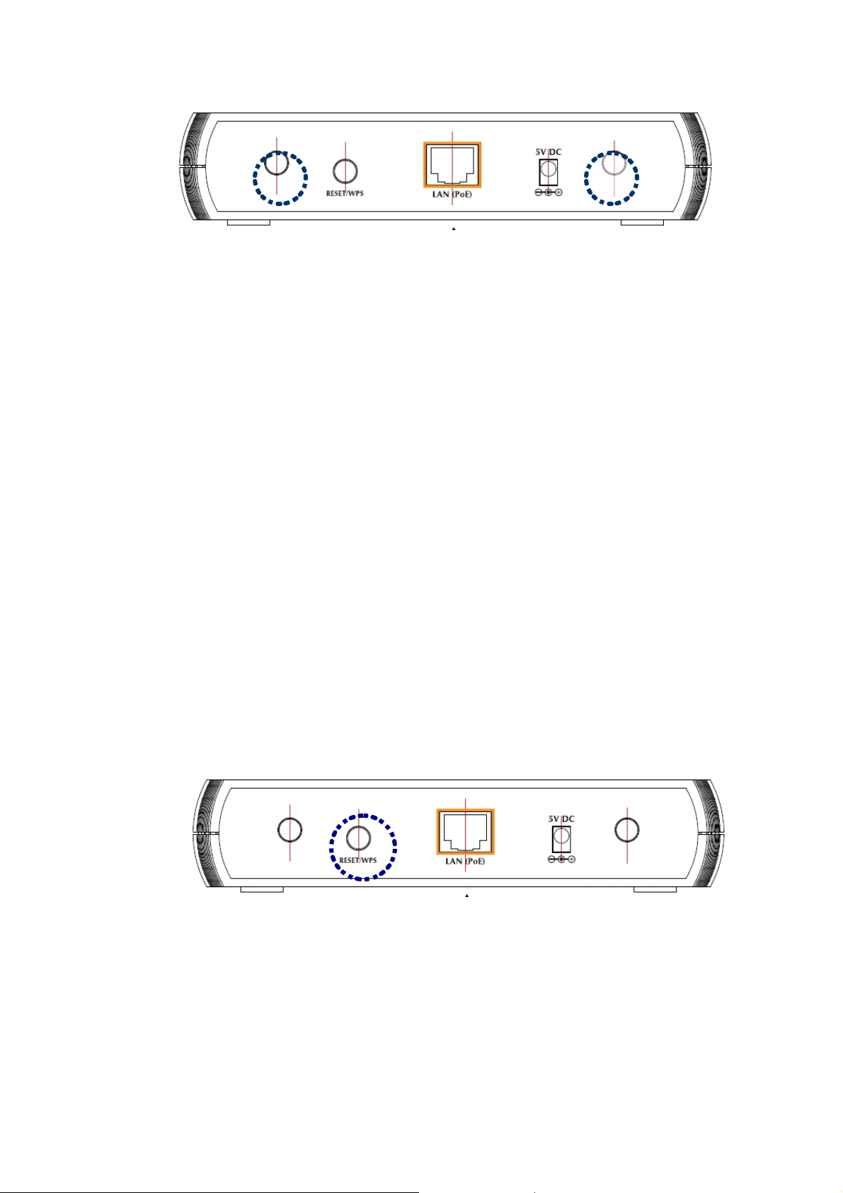
Figure: Rear Panel of 11N AP (example on WNAP-1120PE)
The bundle antennas of 11 N A P are adjustable. Firstly install the antennas pointing straight up, and
then smoothly adjust it if the radio signal strength is poor. But the signal reception is definitely weak
in some certain areas, such as location right down the antenna.
Moreover, with RP-SMA connector, the original antennas of the 11N A P c an be replaced with other
external antennas to extend the coverage. Please check the specification of the antenna you want to
use, and make sure it can be used on 11N AP.
4. WLAN Type
If your 11N AP is installed in an 802.11n and 802.11b/g mixed WLAN, its performance will be
reduced significantly. Because every 802.11n OFDM packet needs to be preced ed by an RTS-CTS
or CTS packet exchange that can be recognized by legacy 802.11b/g devices. This additional
overhead lowers the speed. If there are no 802.11b devices connected, or if connections to all
802.11b/g devices are denied so that your 11N A P can operate in 11n-only mode, then its data rate
shall increased up to 300Mbps.
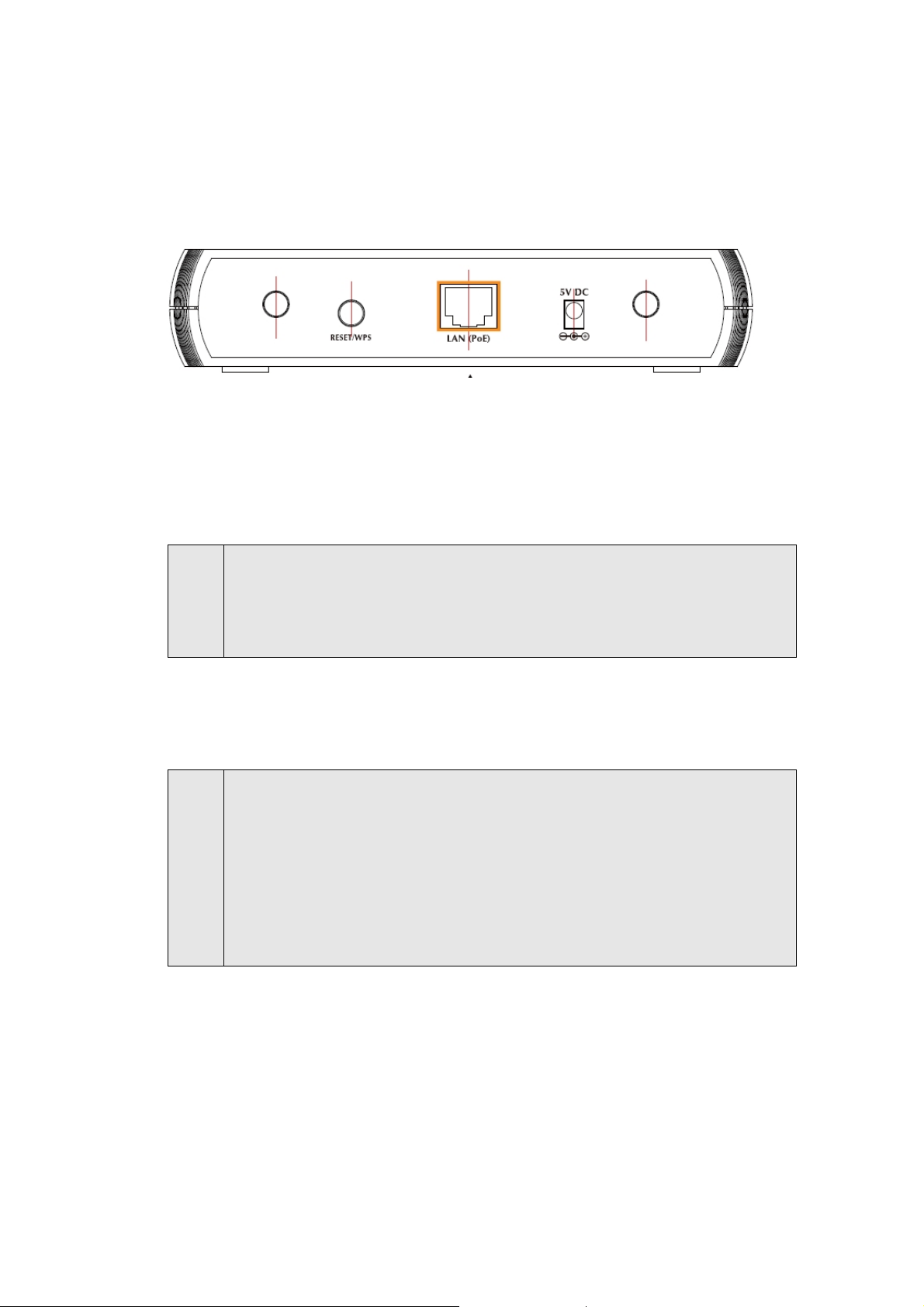
1.5 Reset/WPS Button
Figure: Rear Panel of 11N AP (example on WNAP-1120PE)
The 11N AP provides a Reset button on the rear panel for user to restart or set 11N AP
configuration to factory default.
9

RST / WPS Button
0
This button has two functions:
To Clear All Data and restore the factory default values:
Press the RST (reset) button for longer than 20 seconds until the LED of power
flash, and then the 11N AP will reset itself to the factory default settings.
(Warning: your original config urations will be replaced with the factory default
settings)
To make Wi-Fi Protected Setup (WPS) simple and easier:
Press the WPS button (for less than 3 seconds); machine will start WPS
function to build connection between wireless network clients and this wireless
router.
1
Chapter 2 Hardware Installation
Before you proceed with the installation, it is necessary that you have enough informatio n about the 11N
AP.
1. Locate an optimum location for the 11N AP. T he best place for your 11N A P is usually at the
center of your wireless network, with line of sight to all of your mobile stations.
2. Assemble the antenna to the 11N AP. Try to place them to a position that can best cover your
wireless network. The antenna’s position will enhance the receiving sensitivity.
3. Connect RJ-45 cable to 11N AP. Connect this 11N AP to your LAN switch/hub or a single PC.
Note:
4. Plug in power adapter and connect to power source. After power on, the 11 N AP will start to
The WNAP-1120PE also with IEEE802.3af Power over Ethernet PD (Powered Device)
compliant, you can connect WNAP-1120 to an IEEE802.3af compliant PSE (Power Sourcing
Equipment). The IEEE802.3af complied PSE shall provide the power for the WNAP-1120
after connected.
work.
Note:
1. ONLY use the power adapter supplied with the 11N A P. Otherwise, the product may b e
damaged.
2. ONLY use one power sources for your WNAP-1120PE. That is for WNAP-1120, either
power it from 802.3af PoE or from DC power source.
3. If you want to reset your 11N AP to default settings after it is powered on, press the
Reset button for 20 seconds. Then release the button and wait for 10 seconds for
rebooting.
11
Chapter 3 Web Configuration
Web configuration provides a user-friendly graphical user interface (web pages) to manage your 11N AP.
An AP with an assigned IP address (e.g. http://192.168.1.1) will allow you to monitor and configure (via
web browser e.g., MS Internet Explorer or Netscape).
1. Open your web browser.
2. Enter 11N AP I P address (default IP address is http://192.168.1.1) into the address field. Please also
make sure your PC’s IP address is in the same IP range with 11N AP.
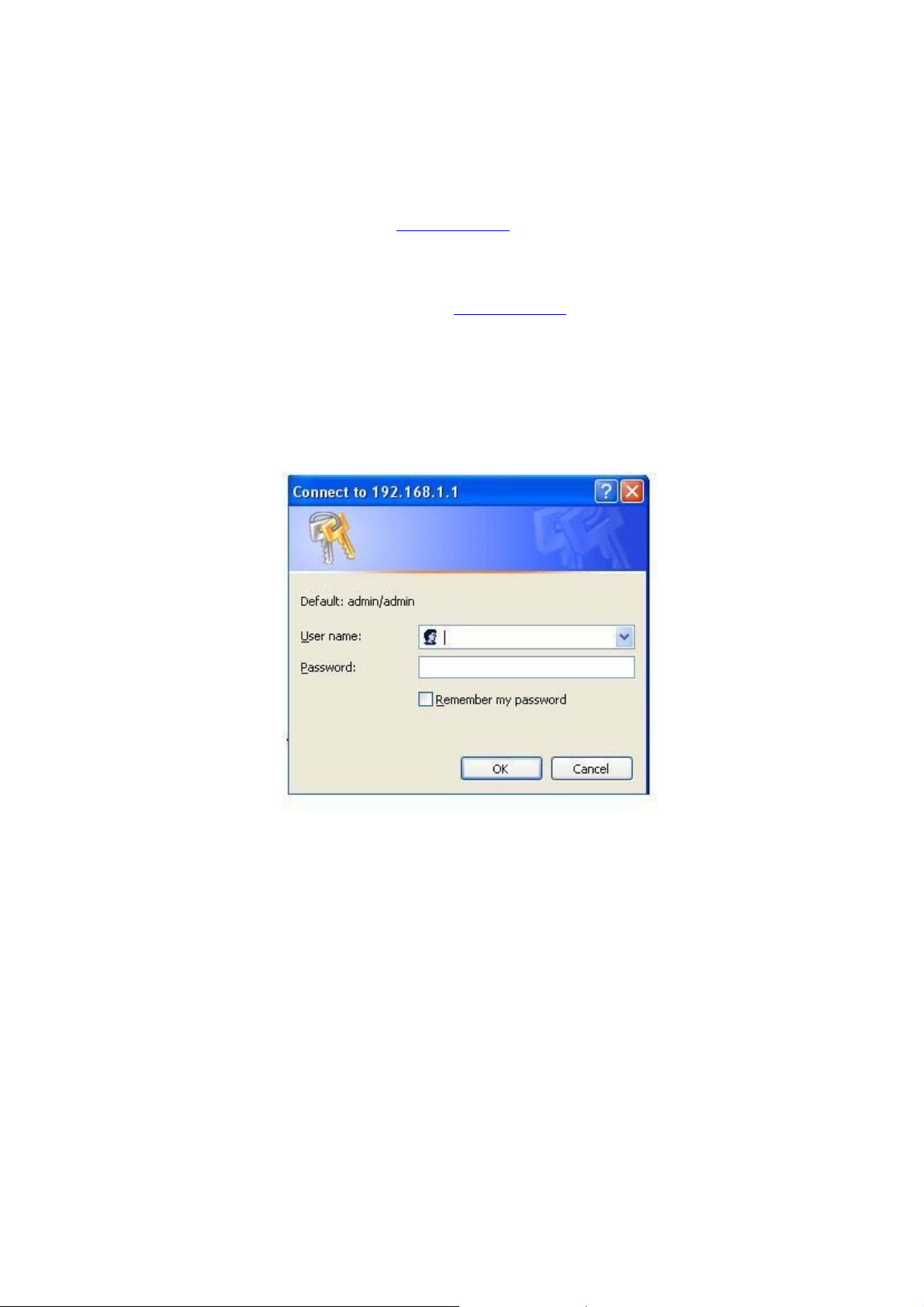
3. A User Name and Password dialog box will appear. Please enter your User Name and Password here.
Default User Name and Password are “admin”. Click “OK” to access the management page.
12
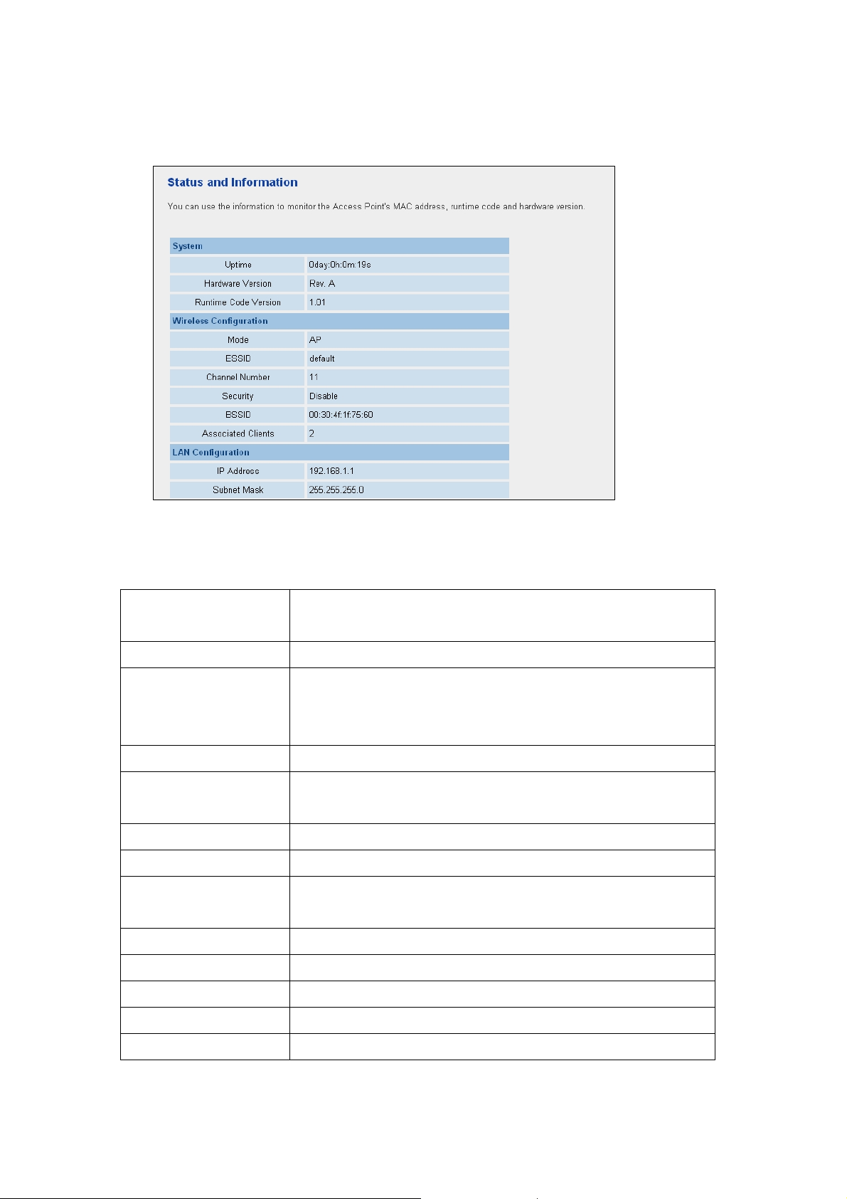
3.1 Home
In this screen, you can check all the information of the 11N AP.
Here are descriptions of every item:
Up time Displays the total passed time since the wireless access point is
powered.
Hardware Version Displays hardware version.
Runtime Code Version Displays current firmware version. If you want to perform firmware
upgrade, this number will help you to determine if you need such
upgrade.
Mode Displays the current wireless operating mode (see next Section)
ESSID Displays current ESSID (the name used to identify this wireless access
point)
Channel Number Displays current wireless channel number
Security Displays current wireless security setting
BSSID Displays current BSSID (a set of unique identification name of this
access point, it can not be modified by user)
Associated Clients Displays the number of connected wireless client
IP Address Displays the IP address of this wireless access point
Subnet Mask Displays the net mask of IP address
Default Gateway Displays the IP address of default gateway
MAC address Displays the MAC address of LAN interface
13
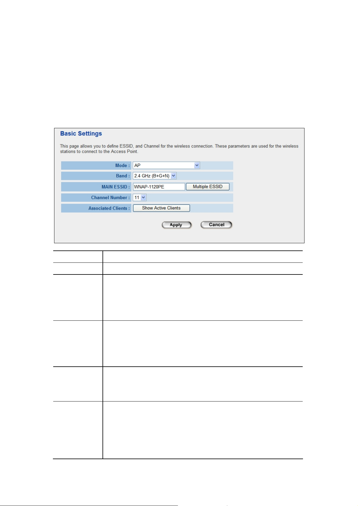
3.2 Basic Setting
In this screen, you can configure the 11 N A P to work in different operating mode. Please refer
to below sections to know the details configuration of each operating mode.
3.2.1 AP Mode
This mode is set to 11N AP by default. It served as a transparent Media Access Control (MAC)
bridge between wired and wireless network.
Parameter Description
Mode Shows the current operation mode.
Band
MAIN ESSID The ESSID (up to 32 printable ASCII characters) is the unique name identified in a
Multiple ESSID T he access point supports multiple SSID function; up to four SSIDs can be set. If
Channel Number Select the appropriate channel from the list provided to correspond with your
2.4GHz (B): It forces the 11N AP to operate in 802.11b only.
2.4GHz (G): It forces the 11N AP to operate in 802.11g only.
2.4GHz (B+G): It allows the 11N AP to operate in 802.11b and 802.11g
simultaneously.
WLAN. The ID prevents the unintentional merging of two co-located WLAN. Please
make sure that the ESSID of all stations in the same WLAN network are the same.
The default value is “default”.
you want to configure additional SSIDs, please click this button. For detailed
descriptions of the function, please refer to Section 3-2-1-1.
network settings. Channels differ from country to country.
Channel 1-11 (North America)
Channel 1-14 (Japan)
Channel 1-13 (Europe)
14
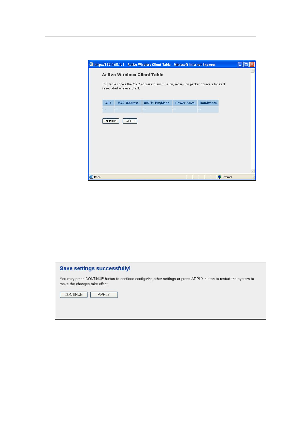
Associated Clients
5
You may press “Show Active Clients” button to check the connected client
information. After the button pressed, you will see the dialog box as below.
You may press “Refresh” to get the new client table or “Close” to close this dialog
box.
After configuration complete, please click “Apply” button to save the configuration. Then you will
see a screen below to prompt you the settings are saving successfully. If you press “Continue”,
you can proceed to configure other settings. However, the new configurations are not take
effect at this time. You must click “Apply”, and then the 11N AP will restart with new
configuration. You may check the LED status to make sure 11N AP finishes the
restart.
1
 Loading...