

Page 1

11n Wireless Access Point
WNAP-1120
User’s Manual
Page 2

Copyright
Copyright © 2009 by PLANET Technology Corp. All rights reserved. No part of this publication may
be reproduced, transmitted, transcribed, stored in a retrieval system, or translated into any language or
computer language, in any form or by any means, electronic, mechan ical, magn etic, optic al, chem ical,
manual or otherwise, without the prior written permission of PLANET.
PLANET makes no representations or warranties, either expressed or implied, with respect to the
contents hereof and specifically disclaims any warranties, merchantability or fitness for any particular
purpose. Any software described in this manual is sold or licensed "as is". Should the pr ograms pro ve
defective following their purchase, the buyer (and not PLANET, its distributor, or its dealer) assumes
the entire cost of all necessary servicing, repair, and any incidental or consequential damages resulting
from any defect in the software. Further, PLANET reserves the right to revise this publication and to
make changes from time to time in the contents hereof without obligation to notify any person of such
revision or changes.
All brand and product names mentioned in this manual are trademarks and/or registered trademarks of
their respective holders.
Federal Communication Commission Interference Statement
This equipment has been tested and found to comply with the limits for a Class B digital device,
pursuant to Part 15 of FCC Rules. These limits are designed to provide reasonable protection against
harmful interference in a residential installation. This equipment generates, uses, and can radiate radio
frequency energy and, if not installed and used in accordance with the instructions, may cause harmful
interference to radio communications. However, there is no guarantee that interference will not occur in
a particular installation. If this equipment does cause harmful interference to radio or television
reception, which can be determined by turning the equipment off and on, the user is enc oura ged to tr y
to correct the interference by one or more of the following measures:
1. Reorient or relocate the receiving antenna.
2. Increase the separation between the equipment and receiver.
3. Connect the equipment into an outlet on a circuit different from that to which the receiver is
connected.
4. Consult the dealer or an experienced radio technician for help.
FCC Caution
To assure continued compliance. (Example-use only shielded interface cables when connecting to
computer or peripheral devices). Any changes or modifications not expressly approved by the party
responsible for compliance could void the user’s authority to operate the equipment.
This device complies with Part 15 of the FCC Rules. Operation is subject to the Following two
conditions: (1) This device may not cause harmful interference, and (2) this Device must accept any
interference received, including interference that may cause undesired operation.
2
Page 3

Federal Communication Commission (FCC) Radiation Exposure
Statement
This equipment complies with FCC radiation exposure set forth for an uncontrol led environment. In
order to avoid the possibility of exceeding the FCC radio frequency exposure limits, human proximity to
the antenna shall not be less than 20 cm (8 inches) during normal operation.
R&TTE Compliance Statement
This equipment complies with all the requirements of DIRECTIVE 1999/5/CE OF THE EUROPEAN
PARLIAMENT AND THE COUNCIL OF 9 March 1999 on radio equipment and telecommunication
terminal Equipment and the mutual recognition of their conformity (R&TTE)
The R&TTE Directive repeals and replaces in the directive 98/13/EEC (Telecommunications Terminal
Equipment and Satellite Earth Station Equipment) As of April 8, 2000.
Safety
This equipment is designed with the utmost care for the safety of those who install and use it. However,
special attention must be paid to the dangers of electric shock and static electricity when working with
electrical equipment. All guidelines of this and of the computer manufacture must therefore be allowed
at all times to ensure the safe use of the equipment.
EU Countries Not Intended for Use
The ETSI version of this device is intended for home and office use in Austria Belgium, Denmark,
Finland, and France (with Frequency channel restrictions). Germany, Greece, Ireland, Italy,
Luxembourg .The Netherlands, Portugal, Spain, Sweden and United Kingdom.
The ETSI version of this device is also authorized for use in EFTA member states Iceland,
Liechtenstein, Norway and Switzerland.
Potential restrictive use
France: Only channels 10, 11, 12 and 13
WEEE regulation
To avoid the potential effects on the environment and human health as a result of the
presence of hazardous substances in electrical and electronic equipment, end users of
electrical and electronic equipment should understand the meaning of the crossed-out
wheeled bin symbol. Do not dispose of WEEE as unsorted municipal waste and have to
collect such WEEE separately.
3
Page 4

Revision
User’s Manual for PLANET 802.11N Wireless Access Point
Model: WNAP-1120v2
Rev: 2.0 (February, 2009)
Part No. EM-WNAP1120v2
4
Page 5

TABLE OF CONTENTS
Chapter 1 Introduction ..................................................................................7
1.1
Package Contents.................................................................................................... 7
1.2
Features...................................................................................................................7
1.3
LED Indicators and Hardware Connection............................................................... 8
1.4
Wireless Performance.............................................................................................. 8
1.5
Reset/WPS Button ................................................................................................... 9
Chapter 2 Hardware Installation.................................................................10
Chapter 3 Web Configuration .....................................................................11
3.1
Home...................................................................................................................... 12
3.2
Basic Setting.......................................................................................................... 13
3.2.1
AP Mode.....................................................................................................................13
3.2.1.1 MUltiple ESSID Setting...........................................................................................................15
3.2.2
Station - Infrastructure Mode......................................................................................16
3.2.3
AP Bridge - Point to Point Mode.................................................................................17
3.2.4
AP Bridge - Point to Multipoint Mode..........................................................................18
3.2.5
AP Bridge - WDS Mode..............................................................................................19
3.2.6
Universal Repeater Mode...........................................................................................22
3.2.7
Security setting of bridge mode..................................................................................24
3.3
WPS Settings......................................................................................................... 25
3.4
Advanced Settings ................................................................................................. 29
3.5
Security .................................................................................................................. 31
3.5.1
WEP...........................................................................................................................32
3.5.2
802.1x.........................................................................................................................34
3.5.3
WPA pre-shared key...................................................................................................35
3.5.4
WPA RADIUS.............................................................................................................36
3.6
RADIUS Server...................................................................................................... 37
3.7
MAC Filtering.......................................................................................................... 39
3.8
System Utility.......................................................................................................... 40
3.9
Wireless Log........................................................................................................... 41
3.10 System Time Zone................................................................................................. 42
5
Page 6

3.11 Configuration.......................................................................................................... 43
3.12 Upgrade.................................................................................................................. 44
3.13 Reset...................................................................................................................... 45
Appendix A Specification............................................................................46
Appendix B Frequently Ask Question........................................................47
6
Page 7

Chapter 1 Introduction
Thank you for purchasing WNAP-1120. This manual guides you on how to install and properly use the
WNAP-1120 in order to take full advantage of its features.
The WNAP-1120 is the 11n Wireless Access Point with 1-port with high speed 300M bps. Fully compliant
with IEEE802.11b/g standard, it provides powerful features such as the Web Configuration, Multiple SSID
/ VLAN tag, Built-in Radius server, MAC filter, WPA2-PSK, WPA and WPA2. With the six wireless
operating modes, establish their wireless easily. Without utility install, user doesn’t need to find the utility
for this product in lots of program list. It can be configured in different OS that provides web browser.
1.1 Package Contents
Make sure that you have the following items:
z 1 x WNAP-1120
z 1 x 12V 1A Power Adapter
z 1 x User’s Manual CD
z 2 x 3dBi External Antenna
z 1 x Ethernet Cable
z 1 x Quick Installation Guide
Note:
If any of the above items are missing, contact your supplier as soon as
possible.
1.2 Features
z Compliant with IEEE 802.11n ( Draft 2.0 ) wireless technology capable of up to 300Mbps
data rate
z Supports Wi-Fi Protected Setup (WPS)
z Compliant with 802.11b / 802.11g standard
z Farther coverage, less dead spaces and higher throughput with 802.11n technology
z Supports 64/128-bit WEP, WPA (TKIP with IEEE 802.1x), WPA2 (AES with IEEE 802.1x)
z AP / Station-Infrastructure / Bridge Point to Point / Bridge Point to Multipoint / WDS /
Repeater modes supported
z Supports DHCP Server
z System monitoring includes Active wireless client Table.
z Easy to use Web-based GUI for configuration and management purposes
z Multiple SSID / 802.11Q tagging function
z MAC filter access control and Built-in Radius Server function
7
Page 8
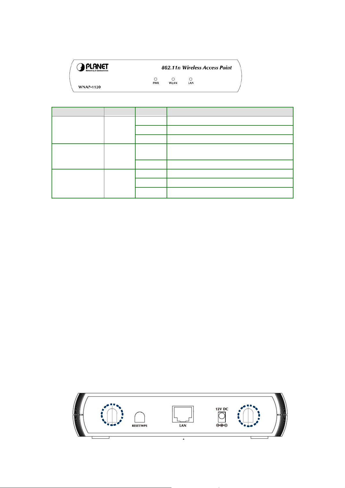
1.3 LED Indicators and Hardware Connection
LED Color STATE MEANING
On Device power on
PWR Green
WLAN Orange
LAN Green
Off Device power off
Blinking During boot up procedure
Blinking
Off Wireless LAN is no function
On Link is established
Blinking Packets are transmitting or receiving
Off LAN port is not connected
Transmitting or receiving data through the Wireless
LAN
1.4 Wireless Performance
The following information will help you utilizing the wireless performance and operating coverage of
WNAP-1120.
1. Site selection
To avoid interferences, please locate WNAP-1120 and wireless client away from transformers,
microwave ovens, heavy-duty motors, fluorescent lights and other industrial equipments. Keep th e
number of walls or ceilings between AP and clients as few as possible. Otherwise the signal strength
may be seriously reduced. Place WNAP-1120 in an open space or add additional WNAP-1120 as
needed to improve the coverage.
2. Environmental factors
The wireless network is easily affected by many environment factors. Every environment is unique
with different obstacles, construction materials, weather, etc. It is hard to determine the exact
operation rage of WNAP-1120 in a specific location without testing.
3. Antenna adjustment
WNAP-1120 1T2R 11n is designed for MIMO technology. The two antennas (circled) are designe d
for TX/RX (Transmitting / Receiving).
8
Page 9
The bundle antennas of WNAP-1120 are adjustable. Firstly install the antennas pointing straight up,
and then smoothly adjust it if the radio signal strength is poor. But the signal reception is definitely
weak in some certain areas, such as location right down the antenna.
Moreover, the original antennas of WNAP-1120 can be replaced with other external antennas t o
extend the coverage. Please check the specification of the antenna you want to use, and make sure
it can be used on WNAP-1120.
4. WLAN Type
If WNAP-1120 is installed in an 802.11n and 802.11b/g mixed WLAN, its performance will be
reduced significantly. Because every 802.11n OFDM packet needs to be preced ed by an RTS-CTS
or CTS packet exchange that can be recognized by legacy 802.11b/g devices. This additional
overhead lowers the speed. If there are no 802.11b devices connected, or if connections to all
802.11b/g devices are denied so that WNAP-1120 can operate in 11n-only mode, then its data rate
should actually 300Mbps.
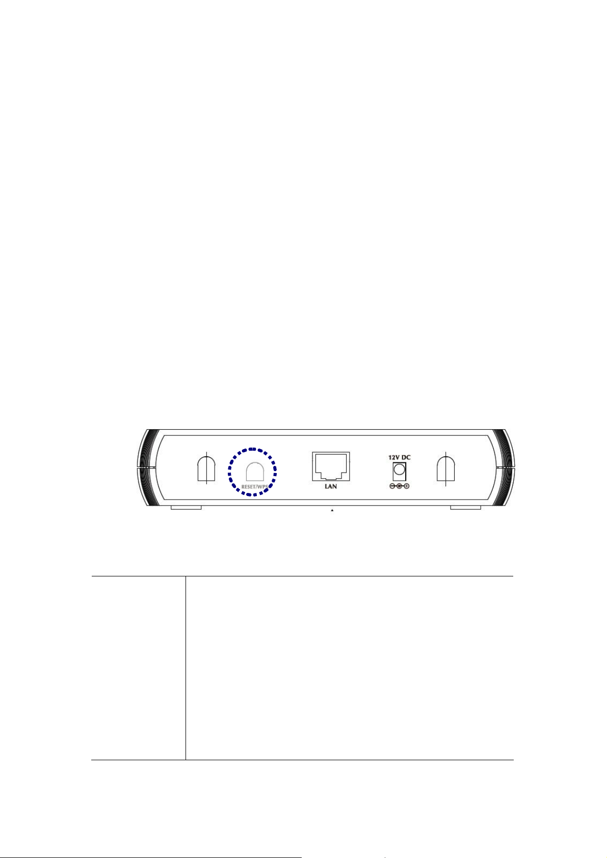
1.5 Reset/WPS Button
WNAP-1120 provides a Reset button on the rear panel for user to restart or set WNAP-1120
configuration to factory default.
RST / WPS Button
This button has two functions:
To Clear All Data and restore the factory default values:
Press the RST (reset) button for longer than 20 seconds until the LED of power
flash, and then the router will reset itself to the factory default settings.
(Warning: your original config urations will be replaced with the factory default
settings)
To make Wi-Fi Protected Setup (WPS) simple and easier:
Press the WPS button (for less than 3 seconds); machine will start WPS
function to build connection between wireless network clients and this wireless
router.
9
Page 10
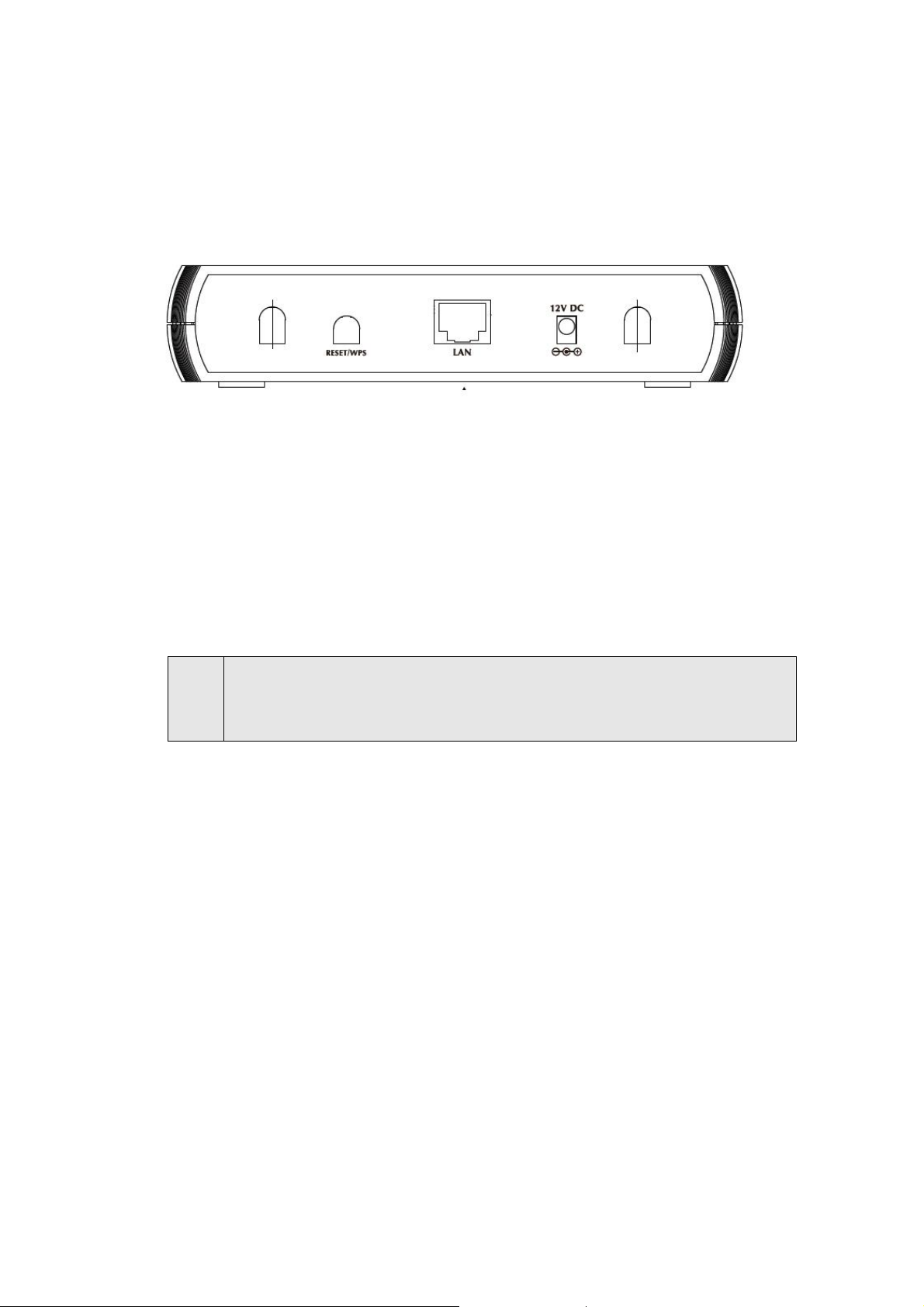
Chapter 2 Hardware Installation
Before you proceed with the installation, it is necessary t hat you have enough information about the
WNAP-1120.
1. Locate an optimum location for the WNAP-1120. The best place for your WNAP-1120 is
usually at the center of your wireless network, with line of sight to all of your mobile stations.
2. Assemble the antenna to WNAP-1120. Try to place them to a position that can best cover your
wireless network. The antenna’s position will enhance the receiving sensitivity.
3. Con nect RJ-45 cable to WNAP-1120. Connect this WNAP-1120 to your LAN switch/hub or a
single PC.
4. Plug in power adapter and connect to power source. After power on, WNAP-1120 will start to
work.
Note:
ONLY use the power adapter supplied with the WNAP-1120. Otherwise, the product may be
damaged. If you want to reset your WNAP-1120 to default settings, press the Reset button
15 seconds. Then release the button and wait for 10 seconds for rebooting.
10
Page 11

Chapter 3 Web Configuration
Web configuration provides a user-friendly graphical user interface (web pages) to manage your
WNAP-1120. An AP with an assigned IP address (e.g. http://192.168.1.1
configure (via web browser e.g., MS Internet Explorer or Netscape).
1. Open your web browser.
2. Enter WNAP-1120 IP address (default IP address is http://192.168.1.1) into the address field. Please
also make sure your PC’s IP address is in the same IP range with WNAP-11 20.
3. A User Name and Password dialog box will appear. Please enter your User Name and Password here.
Default User Name and Password are “admin”. Click “OK” to access the management page.
) will allow you to monitor and
11
Page 12
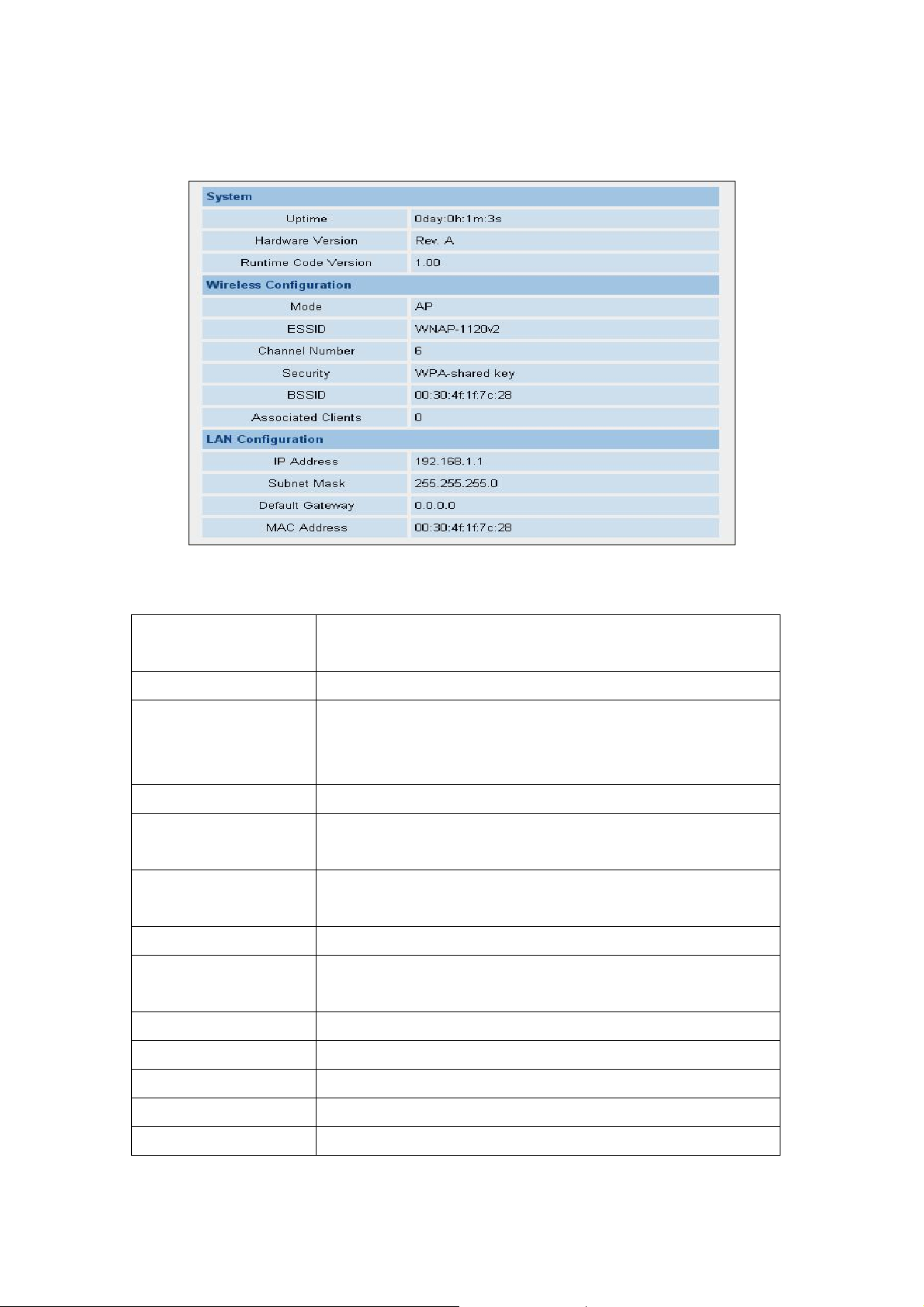
3.1 Home
In this screen, you can check all the information of WNAP-1120.
Here are descriptions of every item:
Up time Displays the total passed time since the wireless access point is
powered.
Hardware Version Displays hardware version.
Runtime Code Version Displays current firmware version. If you want to perform firmware
upgrade, this number will help you to determine if you need such
upgrade.
Mode Displays current wireless operating mode (see next Section)
ESSID Displays current ESSID (the name used to identify this wireless
access point)
Channel
Number
Security Displays current wireless security setting
BSSID Displays current BSSID (a set of unique identification name of this
Associated Clients Displays the number of connected wireless client
Displays current wireless channel number
access point, it can not be modified by user)
IP Address Displays the IP address of this wireless access point
Subnet Mask Displays the net mask of IP address
Default Gateway Displays the IP address of default gateway
MAC address Displays the MAC address of LAN interface
12
Page 13
3.2 Basic Setting
In this screen, you can configure WNAP-1120 to work in different operating mode. Please refer
to below sections to know the details configuration of each operating mode.
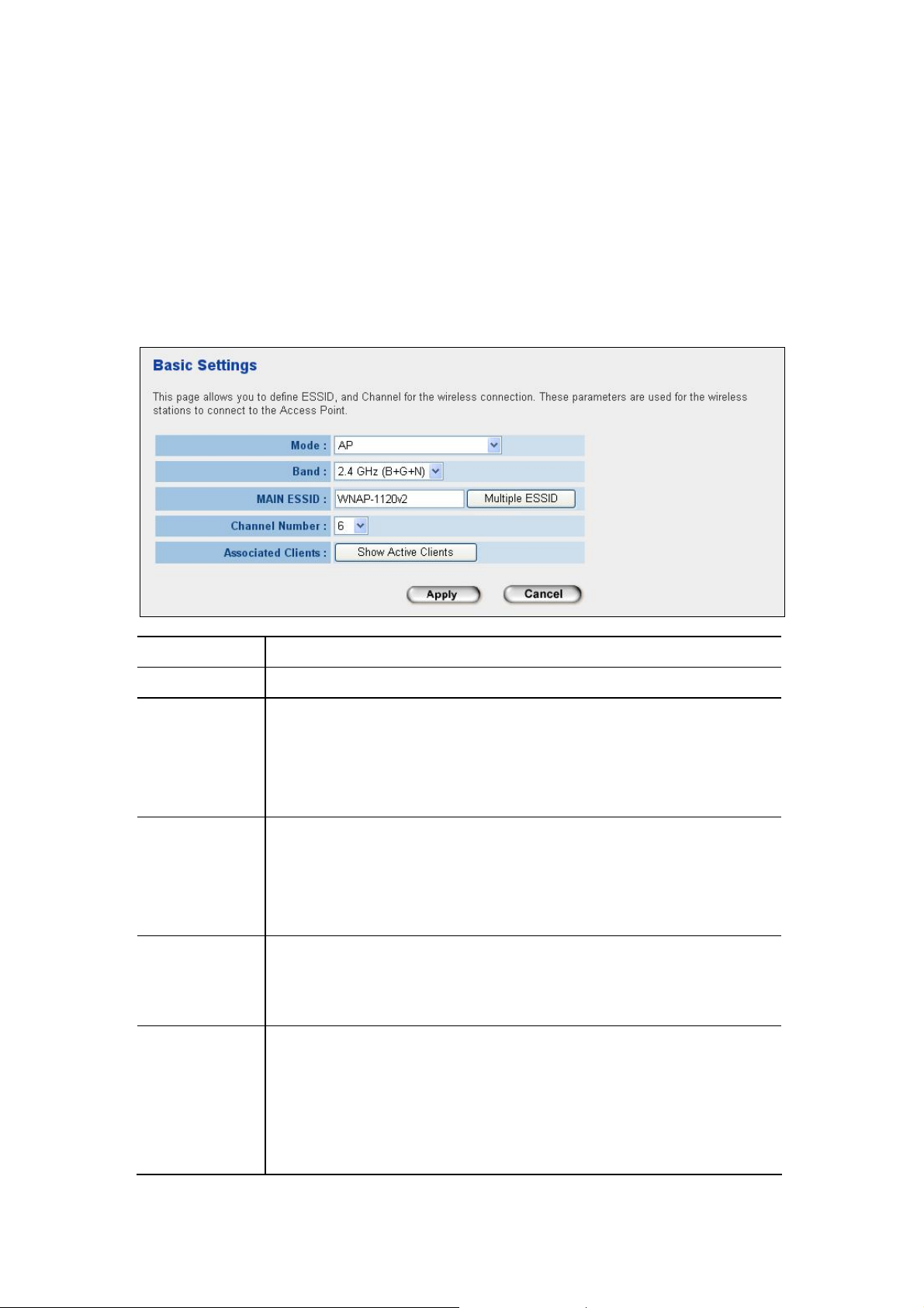
3.2.1 AP Mode
This mode is set to WNAP-1120 by default. It served as a transparent Media Access Control
(MAC) bridge between wired and wireless network.
Parameter Description
Mode Shows the current operation mode.
Band
MAIN ESSID The ESSID (up to 32 printable ASCII characters) is the unique nam e identif ied in a
Multiple ESSID The access point supports multiple SSID function; up to four SSIDs can be set. If
Channel Number Select the appropriate channel from the list provided to correspond with your
2.4GHz (B): It forces the WNAP-1120 to operate in 802.11b only.
2.4GHz (G): It forces the WNAP-1120 to operate in 802.11g only.
2.4GHz (B+G): It allows the WNAP-1120 to operate in 802.11b and 802.11g
simultaneously.
WLAN. The ID prevents the unintentional merging of two co-located WLAN. Please
make sure that the ESSID of all stations in the same WLAN network are the same.
The default value is “default”.
you want to configure additional SSIDs, please click this button. For detailed
descriptions of the function, please refer to Section 3-2-1-1.
network settings. Channels differ from country to country.
Channel 1-11 (North America)
Channel 1-14 (Japan)
Channel 1-13 (Europe)
13
Page 14
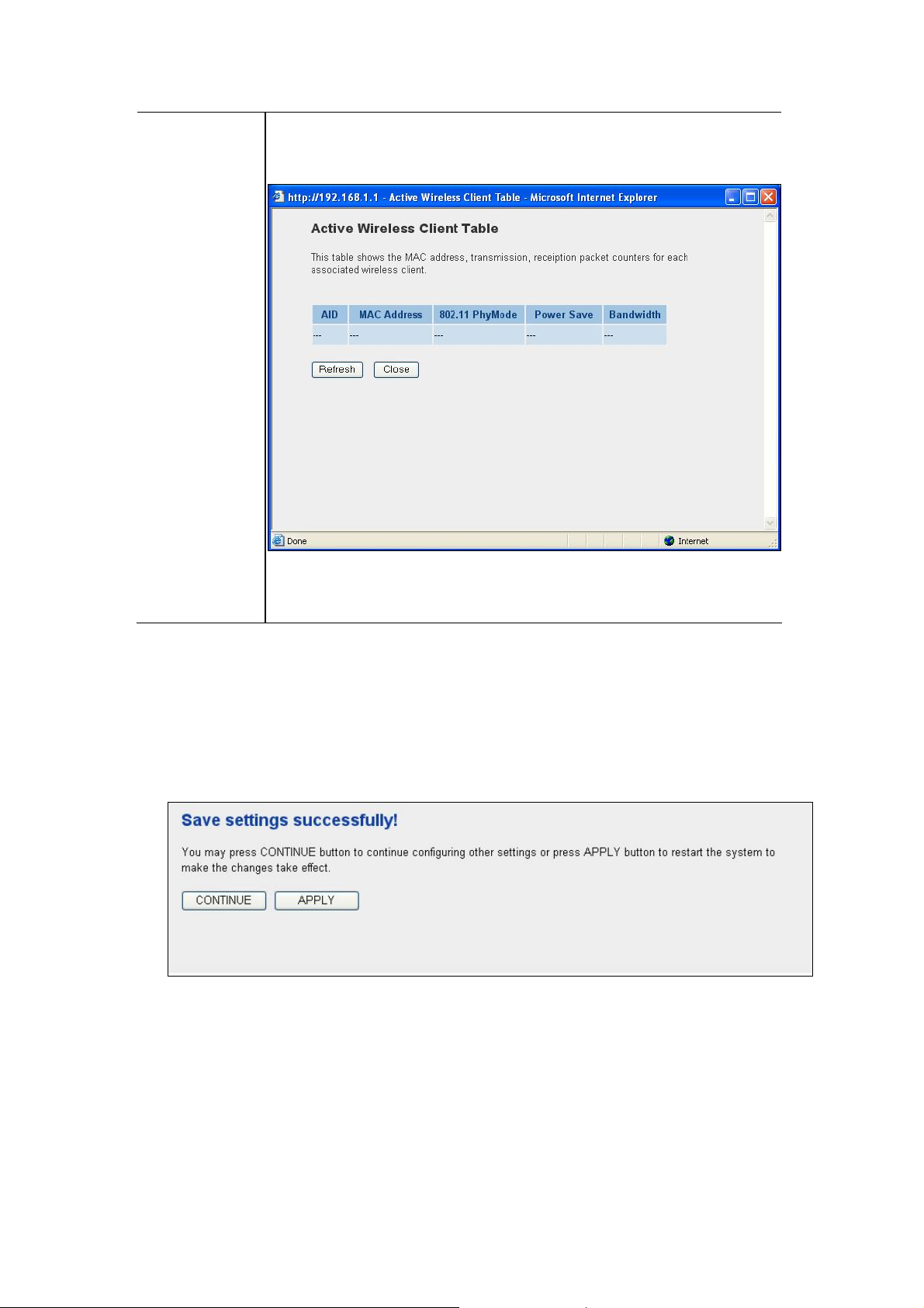
Associated Clients
You may press “Show Active Clients” button to check the connected client
information. After the button pressed, you will see the dialog box as below.
You may press “Refresh” to get the new client table or “Close” to close this dialog
box.
After configuration complete, please click “Apply” button to save the configuration. Then you will
see a screen below to prompt you the settings are saving successfully. If you press “Continue”,
you can proceed to configure other settings. However, the new configurations are not take
effect at this time. You must click “Apply”, and then the WNAP-1120 will restart with new
configuration. You may check the LED status to make sure WNAP-1120 finishes the
restart.
14
Page 15
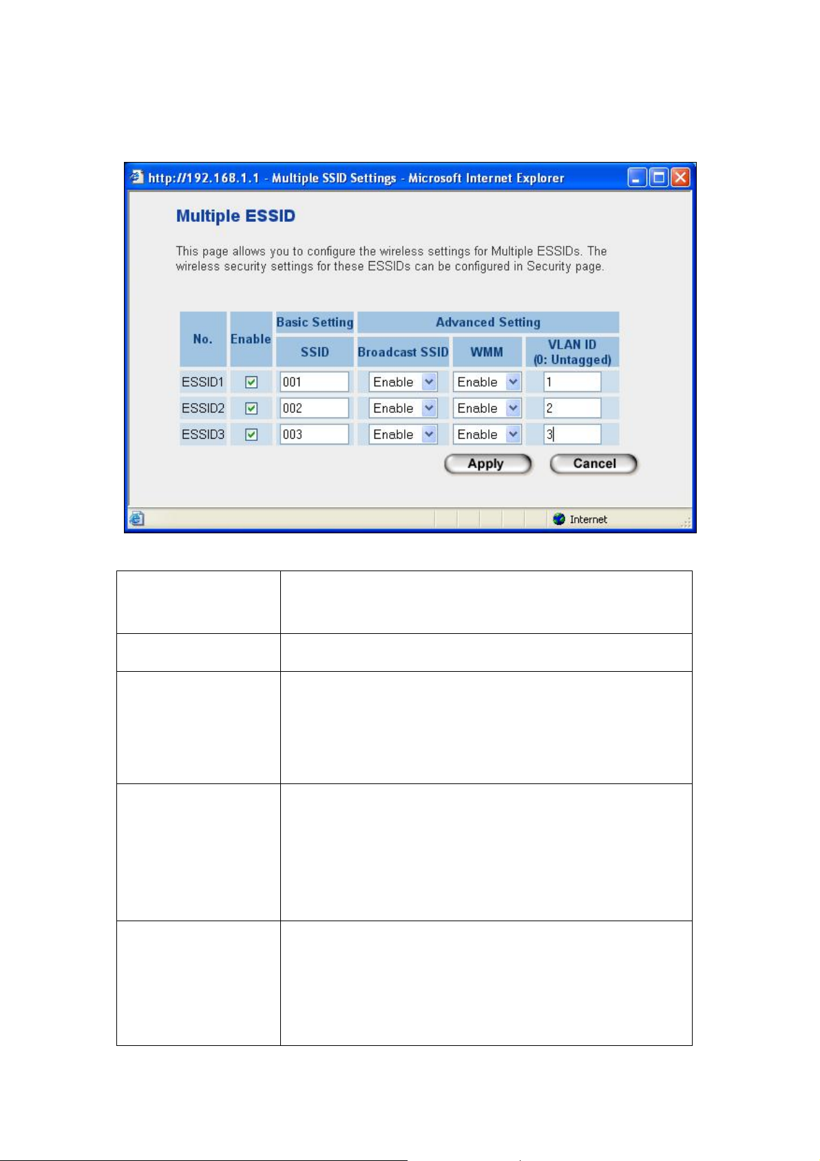
3.2.1.1 MULTIPLE ESSID SETTING
Here are descriptions of every setup item:
No. Except Main SSID, you can configure additional three ESSID
here.
Enable Select the box to enable the different additional ESSID.
SSID Please input the SSID name (the name used to identify this
wireless access point) here. You can input up to 32
alphanumerical characters. PLEASE NOTE THAT ESSID IS
CASE SENSITIVE.
Broadcast SSID Decide if the wireless access point will broadcast its own
ESSID or not. You can hide the ESSID of your wireless access
point (set the option to ‘Disable’), so only people those who
know the ESSID of your wireless access point can get
connected.
WMM WMM (Wi-Fi Multimedia) technology, which can improve the
performance of certain network applications, like audio/video
streaming, network telephony (VoIP), and others. When you
enable WMM function, the access point will define the priority
of different kinds of data, to give higher priority to applications
15
Page 16

which require instant responding. Therefore you can improve
the performance of such network applications.
VLAN ID
(0:Untagged)
If your network uses VLANs, you can assign the SSID to a
VLAN on your network. Client devices that associate using the
SSID are grouped into this VLAN. The VLAN ID range is from 1
to 4094. The VLAN ID is 0 by default (VID range is “0~4904”), it
means that disable the VLAN function for the ESSID.
3.2.2 Station - Infrastructure Mode
WNAP-1120 serves as a wireless station (infrastructure) in this mode. Connected to a PC or a
small LAN (no more than 2 PCs), it allows the PC or small LAN able to access the wireles s
network via Access Point.
16
Page 17

Parameter
Mode Shows the current operation mode.
Description
Band
ESSID Please make sure the ESSID of the wireless network that you will connect
WLAN MAC
After configuration complete, please click “Apply” button to save the configuration. Then you will
see a screen to prompt you the settings are saving successfully. You may press “Co ntinue” for
configure other settings or “Apply” to restart WNAP-1120 with new configuration.
2.4GHz (B): It forces the WNAP-1120 to operate in 802.11b only.
2.4GHz (G): It forces the WNAP-1120 to operate in 802.11g only.
2.4GHz (N): It forces the WNAP-1120 to operate in 802.11n only.
2.4GHz (B+G): It allows the WNAP-1120 to operate in 802.11b and
802.11g simultaneously.
2.4GHz (B+G+N): It allows the WNAP-1120 to operate in 802.11b,
802.11g, and 802.11n simultaneously.
and enter the correct value in this field. The default SSID is “default”.
Keep default setting: WNAP-1120 will use its own MAC address to
access the wireless LAN.
Press “MAC Clone” button: It will use PC’s MAC address to access the
wireless LAN.
3.2.3 AP Bridge - Point to Point Mode
This function allows WNAP-1120 to bridge 2 wired Ethernet networks wirelessly.
Parameter
Mode Shows the current operation mode.
Description
Band
2.4GHz (B): It forces the WNAP-1120 to operate in 802.11b only.
2.4GHz (G): It forces the WNAP-1120 to operate in 802.11g only.
17
Page 18

2.4GHz (N): It forces the WNAP-1120 to operate in 802.11n only.
2.4GHz (B+G): It allows the WNAP-1120 to operate in 802.11b and 802.11g
simultaneously.
2.4GHz (B+G+N): It allows the WNAP-1120 to operate in 802.11b, 802.11g, and
802.11n simultaneously.
Channel Number Select the appropriate channel from the list provided to correspond with your
network settings. Channels differ from country to country.
Channel 1-11 (North America)
Channel 1-14 (Japan)
Channel 1-13 (Europe)
MAC Address 1
Set Security IF you want to enable security to protect your wireless connection. Please press
After configuration complete, please click “Apply” button to save the configuration. Then you will
see a screen to prompt you the settings are saving successfully. You may press “Co ntinue” for
configure other settings or “Apply” to restart WNAP-1120 with new configuration.
Keep default setting: WNAP-1120 will use its own MAC address to access the
wireless LAN.
Press “MAC Clone” button: It will use PC’s MAC address to access the
wireless LAN.
“Set Security” button and refer to section “3.2.8 Security setting for bridge mode”
to configure the detail settings.
3.2.4 AP Bridge - Point to Multipoint Mode
This function allows WNAP-1120 to bridge more than 2 wired Ethernet networks together b y
wireless connection.
18
Page 19

Parameter Description
Mode Shows the current operation mode.
Band
Channel Number Select the appropriate channel from the list provided to correspond with your
MAC Address 1~4 If you want to bridge multiple WNAP-1120 in this mode, you have to enter the MAC
Set Security IF you want to enable security to protect your wireless connection. Please press
2.4GHz (B): It forces the WNAP-1120 to operate in 802.11b only.
2.4GHz (G): It forces the WNAP-1120 to operate in 802.11g only.
2.4GHz (N): It forces the WNAP-1120 to operate in 802.11n only.
2.4GHz (B+G): It allows the WNAP-1120 to operate in 802.11b and 802.11g
simultaneously.
2.4GHz (B+G+N): It allows the WNAP-1120 to operate in 802.11b, 802.11g, and
802.11n simultaneously.
network settings. Channels differ from country to country.
Channel 1-11 (North America)
Channel 1-14 (Japan)
Channel 1-13 (Europe)
addresses of other WNAP-1120 into the fields.
“Set Security” button and refer to section “3.2.8 Security setting for bridge mode” to
configure the detail settings.
After configuration complete, please click “Apply” button to save the configuration. Then you will see
a screen to prompt you the settings are saving successfully. You may press “Continue” for configure
other settings or “Apply” to restart WNAP-1120 with new configuration.
3.2.5 AP Bridge - WDS Mode
If you want WNAP-1120 to bridge to other WNAP-1120 and provide access for other wireless
clients at the same time, you have to set the WNAP-1120 to “AP Bridge - WDS”. Simply
speaking, “AP Bridge - WDS” function is the combination of “AP mode” and “AP Bridge-Point to
Multi-Point mode”.
19
Page 20

Parameter Description
Mode Shows the current operation mode.
Band
ESSID The ESSID (up to 32 printable ASCII characters) is the unique name identified in a
Channel Number Select the appropriate channel from the list provided to correspond with your
2.4GHz (B): It forces the WNAP-1120 to operate in 802.11b only.
2.4GHz (G): It forces the WNAP-1120 to operate in 802.11g only.
2.4GHz (N): It forces the WNAP-1120 to operate in 802.11n only.
2.4GHz (B+G): It allows the WNAP-1120 to operate in 802.11b and 802.11g
simultaneously.
2.4GHz (B+G+N): It allows the WNAP-1120 to operate in 802.11b, 802.11g, and
802.11n simultaneously.
WLAN. The ID prevents the unintentional merging of two co-located WLANs.
Please make sure that the ESSID of all stations in the same WLAN network are the
same. The default value is “default”.
network settings. Channels differ from country to country.
Channel 1-11 (North America)
Channel 1-14 (Japan)
Channel 1-13 (Europe)
Associated Clients You may press “Show Active Clients” button to check the connected client
information. After the button pressed, you will see the dialog box as below:
20
Page 21

You may press “Refresh” to get the new client table or “Close” to close this dialog
box.
MAC Address 1 ~4 If you want to bridge multiple WNAP-1120 in this mode, you have to enter the MAC
addresses of other WNAP-1120 into the fields.
Set Security IF you want to enable security to protect your wireless connection. Please press
“Set Security” button and refer to section “3.2.7 Security setting for bridge mode” to
configure the detail settings.
After configuration complete, please click “Apply” button to save the configuration. Then you will
see a screen to prompt you the settings are saving successfully. You may press “Co ntinue” for
configure other settings or “Apply” to restart WNAP-1120 with new configuration.
21
Page 22

3.2.6 Universal Repeater Mode
This mode allows you to extend the range of your wireless network. When the AP is configured
to repeater mode, it will repeat the wireless signal from wireless client to access point. Thus,
the wireless connection distance can be extended. However, the performance will become
half of normal performance when client connect to a Repeater. Besides, when the
WNAP-1120 is configured to repeater mode, you can only manage the AP through LAN
interface and the PC(s) connected to its LAN port cannot communicate with other wireless
clients.
Parameter Description
Mode Shows the current operation mode.
Band
ESSID The ESSID (up to 32 printable ASCII characters) is the unique name identified in a
2.4GHz (B): It forces the WNAP-1120 to operate in 802.11b only.
2.4GHz (G): It forces the WNAP-1120 to operate in 802.11g only.
2.4GHz (N): It forces the WNAP-1120 to operate in 802.11n only.
2.4GHz (B+G): It allows the WNAP-1120 to operate in 802.11b and 802.11g
simultaneously.
2.4GHz (B+G+N): It allows the WNAP-1120 to operate in 802.11b, 802.11g, and
802.11n simultaneously.
WLAN. The ID prevents the unintentional merging of two co-located WLANs.
Please make sure that the ESSID of all stations in the same WLAN network are the
same. The default value is “default”.
Channel Number Select the appropriate channel from the list provided to correspond with your
network settings. Channels differ from country to country.
22
Page 23

Channel 1-11 (North America)
Channel 1-14 (Japan)
Channel 1-13 (Europe)
Associated Clients You may press “Show Active Clients” button to check the connected client
information. After the button pressed, you will see the dialog box as below.
You may press “Refresh” to get the new client table or “Close” to close this dialog
box.
WLAN MAC
Root AP SSID
Keep default setting: WNAP-1120 will use its own MAC address to access the
wireless LAN.
Press “MAC Clone” button: It will use PC’s MAC address to access the wireless
LAN.
In “Universal Repeater mode”, this device can act as a station to connect t o
a Root AP. You should enter the SSID of the Root AP here.
After configuration complete, please click “Apply” button to save the configuration. Then you will
see a screen to prompt you the settings are saving successfully. You may press “Co ntinue” for
configure other settings or “Apply” to restart WNAP-1120 with new configuration.
23
Page 24

3.2.7 Security setting of bridge mode
In “AP Bridge-Point to Point mode”, “AP Bridge-Point to Multi-Point mode” and “AP Bridge-WDS
mode”, you can click “Set Security” to add encryption for the communication between the
bridged access points. This can protect your wireless network.
Parameter Description
Encryption
Key Format
WEP Key
Pre-shared Key
You can select “None”,“WEP 64bits”, “WEP 128bits”, “WPA (TKIP)” or “WPA2
(AES)” of this option . It is set to “None” by default.
This is only used when you select “WEP 64bits” or “WEP 128bits” encryption
method. You may select to select ASCII Characters (alphanumeric format) or
Hexadecimal Digits (in the “A-F”, “a-f” and “0-9” range) to be the WEP Key.
This is only used when you select “WEP 64bits” or “WEP 128bits” encryption
method. The WEP key is used to encrypt data transmitted between the bridged
access points. Fill the text box by following the rules below.
64-bit WEP: input 10-digit Hex values (in the “A-F”, “a-f” and “0-9” range) or 5-digit
ASCII character as the encryption keys.
128-bit WEP: input 26-digit Hex values (in the “A-F”, “a-f” and “0-9” range) or
10-digit ASCII characters as the encryption keys.
This is only used when “WPA” or “WPA2” is selected. You may use Passphrase
Format
(alphanumeric format) or Hexadecimal Digits (in the “A-F”, “a-f” and “0-9” range) to
be the Pre-shared Key.
24
Page 25

Pre-shared Key This is only used when “WPA” or “WPA2” is selected. The Pre-shared key is used to
authenticate and encrypt data transmitted between the bridged access points. Fill
the text box by following the rules below.
Hex (64 characters): input 64-digit Hex values (in the “A-F”, “a-f” and “0-9” range)
Passphrase: at least 8 characters.
After configuration complete, please click “Apply” button to save the configuration. Then you will
see a screen to prompt you the settings are saving successfully. You may press “Co ntinue” for
configure other settings or “Apply” to restart WNAP-1120 with new configuration.
3.3 WPS Settings
Wi-Fi Protected Setup (WPS) is the simplest way to build connection between wireless net work clients
and this wireless router. You don’t have to select encryption mode and input a long encryption pass
phrase every time when you need to setup a wireless client, you only have to press a button on wireless
client and router, and the WPS will do the rest for you.
This wireless router supports two types of WPS: Push-Button Configuration (PBC), and PIN code. If you
want to use PBC, you have to push a specific button on the wireless client to start WPS mode, and switch
this wireless router to WPS mode too. You can push RET/WPS button of this wireless router, or click
‘Start PBC’ button in the web configuration interface to do this. If you want to use PIN code, you can see
the setup as below.
25
Page 26

Parameters Description
Enable WPS Check this box to enable WPS function, uncheck it to disable WPS.
Wi-Fi Protected
Setup Information
WPS Status
Self PIN code
SSID The SSID of this wireless router will be displayed here.
Authentication
Mode
Passphrase Key
Device Configure
WPS-related system information will be displayed here.
If the wireless security (encryption) function of this wireless router is properly set,
you’ll see ‘Configured’ message here. If wireless security function has not been set,
you’ll see ‘unConfigured’.
This is the WPS PIN code of this wireless router. This code is useful when
WNAP-1120 router sets as Enrollee, you need to fill this number into the web page
of the other device.
The wireless security authentication mode of this wireless router will be displayed
here.
Confirming your Identity Key Store Pass-phrase. It is allowed you to easily
remember the key what you may want to remember is that if the passphrase is
used,
Config Mode: “Registrar”, “Enrollee”, please see the setup step as below.
Click ‘Start PBC’ to start Push-Button style WPS setup procedure. This wireless
Configure via Push
Button
Configure via Pin
Code
router will wait for WPS requests from wireless clients for 2 minutes. The ‘WLAN’
LED on the wireless router will be steady on when this wireless router is waiting for
incoming WPS request.
Please input the PIN code of the other device you wish to connect, and click ‘Start
PIN’ button. The ‘WLAN’ led on the wireless router will be steady on when this
wireless router is waiting for incoming WPS request. (Please see the detail as
below.)
26
Page 27

PBC setup step:
1. Ensure you have set the security setting on WNAP-1120 (as Registrar).
2. Click the WPS button on WNAP-1120 (or the “Start PBC” button on the web interface of WNAP-1120)
and the other device (supports PBC function) in 2 minutes.
3. WNAP-1120 (Registrar) would send SSID and security key to the other device (Enrollee) through
tunnel to connect.
4. If you see the wireless client in the list, WPS-PBC setting is successful.
27
Page 28

PIN (as Registrar) setup step:
1. Select Config Mode: “Registrar” on WNAP-1120.
2. Fill the PIN code of the other device (as Enrollee that support WPS-PIN setting) into the “configure via
Client Pin code” of WNAP-1120.
3. Click the PIN buttons on WNAP-1120 and the other device in 2 minutes.
4. If you see the wireless client in the list, WPS-PIN setting is successful.
PIN (as Enrollee) setup step:
1. Select Config Mode: “Enrollee” on WNAP-1120.
2. Fill the PIN code of WNAP-1120 into the other device (as Registrar).
3. Click the PIN buttons on WNAP-1120 and the other device in 2 minutes.
4. If you see the wireless client in the list, WPS-PIN setting is successful.
** As the figure as above, just change two roles.
28
Page 29

3.4 Advanced Settings
You should not change these advanced parameters unless you know what effect the changes will
have on this access point.
Parameter Description
Fragment Threshold “Fragment Threshold” specifies the maximum size of packet during the
fragmentation of data to be transmitted. If you set this value too low, it will
result in bad performance.
what it is, default value is 2346
RTS Threshold When the packet size is smaller than the RTS threshold, the access point will
not use the RTS/CTS mechanism to send this packet. Do not modify
default value if you don’t know what it is, default value is 2347
Beacon Interval The interval of time that this access point broadcast a beacon. Beacon is
used to synchronize the wireless network.
you don’t know what it is, default value is 100
Data Rate The “Data Rate” is the rate this access point uses to transmit data packets.
The access point will use the highest possible selected transmission rate to
transmit the data packets.
N Data Rate Set the data rate of 802.11 Draft-N clients, available options are MCS 0 to
Do not modify default value if you don’t know
Do not modify default value if
MCS 15, it’s safe to set this option to ‘Auto’ and it’s not necessary to change
this value unless you know what will happen after modification.
Channel Width Select wireless channel width (bandwidth taken by wireless signals of this
access point). It’s suggested to select ‘Auto 20/40MHz’. Do not change to ’20
MHz’ unless you know what it is.
29
Page 30

Preamble Type Preamble type defines the length of CRC block in the frames during the
wireless communication. “Short Preamble” is suitable for high traffic wireless
network. “Long Preamble” can provide more reliable communication.
Broadcast ESSID If you enable “Broadcast ESSID”, every wireless station located within the
coverage of this access point can discover this access point easily. If you are
building a public wireless network, enabling this feature is recommended.
Disabling “Broadcast ESSID” can provide better security.
WMM WMM (Wi-Fi Multimedia) technology, which can improve the performance of
certain network applications, like audio/video streaming, network telephony
(VoIP), and others. When you enable WMM function, the access point will
define the priority of different kinds of data, to give higher priority to
applications which require instant responding. Therefore you can improve
the performance of such network applications.
CTS Protect Enabling this setting will reduce the chance of radio signal collisions
between 802.11b and 802.11g wireless access points. It’s recommended to
set this option to ‘Auto’.
TX Power You can set the output power of wireless radio. Unless you’re using this
wireless access point in a really big space, you may not have to set output
power to 100%. This will enhance security (malicious / unknown users in
distance will not be able to reach your wireless access point).
Watch dog W hen you set the important Server in the same IP range topology , key the
IP address in the Watch host space and set the time ( 1~60 minutes ). When
there is large traffic in the topology, you can not login the server during th e
setting time. The WNAP-1120 will reboot to solve the traffic jam status.
Block Relay When you enable the function, the WNAP-1120 wireless users can not ping
each other.
After configuration complete, please click “Apply” button to save the configuration. Then you will
see a screen to prompt you the settings are saving successfully. You may press “Continue” for
configure other settings or “Apply” to restart WNAP-1120 with new configuration.
30
Page 31
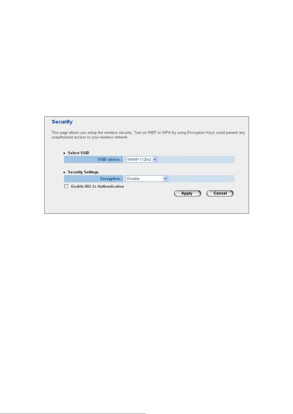
3.5 Security
This Access Point provides complete wireless LAN security functions, includes WEP, 802.1x,
802.1x with WEP, WPA-PSK and WPA RADIUS. With these security functions, you can prevent
your wireless LAN from illegal access. Please make sure your wireless stations use the sam e
security mechanism. In default, the security option is “Disable”.
Note: This access point can act as a station and an AP at the same time in “Universal
Repeater” mode. The security settings only apply to AP operation in “Universal Repeater” mode.
The station operation has no security.
31
Page 32

3.5.1 WEP
When you select 64-bit or 128-bit WEP key, you have to enter WEP keys to encrypt data. You
can enter four WEP keys and select one of them as default key. Then the access point will only
allow the clients configured with the same encryption keys for associ ation. You can use WEP
encryption in “AP mode”, “Station-Ad Hoc mode”, “Station-Infrastructure mode”, “AP
Bridge-WDS mode” and “Universal Repeater mode”.
If you would like to enable 802.1x Authentication also, please check the “Enable 802.1x
Authentication” and refer to section 3.4.2 for the detail settings.
Parameter Description
Encryption Select “WEP” in this option.
Key Length You can select the 64 or 128-bit key to encrypt transmitted data. Larger
WEP key length will provide higher level of security, but the throughput
will be lower.
Key Format You may select to select ASCII Characters (alphanumeric format) or
Hexadecimal Digits (in the “A-F”, “a-f” and “0-9” range) to be the WEP
Key.
Default Tx Key Select one of the four keys to encrypt your data.
Encryption Key 1 - Key 4 The WEP keys are used to encrypt data transmitted in the wireless
network. Fill the text box by following the rules below.
64-bit WEP: input 10-digit Hex values (in the “A-F”, “a-f” and “0-9”
range) or 5-digit ASCII character as the encryption keys.
128-bit WEP: input 26-digit Hex values (in the “A-F”, “a-f” and “0-9”
range) or 10-digit ASCII characters as the encryption keys.
32
Page 33

Enable 802.1x Authentication Check this box when you want to enable 802.1x authentication with
WEP encryption. You may refer to section 3.4.2 for detail settings.
After configuration complete, please click “Apply” button to save the configuration. Then you will
see a screen to prompt you the settings are saving successfully. You may press “Continue” for
configure other settings or “Apply” to restart WNAP-1120 with new configuration.
33
Page 34

3.5.2 802.1x
IEEE 802.1x is an authentication protocol. Every user must use a valid account to lo gin to this
Access Point before accessing the wireless LAN. The authentication is processed by a RADIUS
server. This mode only authenticates user by IEEE 802.1x, but it does not encryption the data
during communication. It is suggested to enable 802.1x and WEP at the same time.
Parameter Description
Encryption If you want to use 802.1x onl y, keep this setting in “Disable”.
Enable 802.1x Authentication Check this option to enable 802.1x function.
Use Internal MD5/PEAP
RADIUS Server
RADIUS Server IP Address
RADIUS Server Port
RADIUS Server Password
After configuration complete, please click “Apply” button to save the configuration. Then you will
see a screen to prompt you the settings are saving successfully. You may press “Co ntinue” for
configure other settings or “Apply” to restart WNAP-1120 with new configuration.
WNAP-1120 has built in a RADIUS server. You can check this option to
make the 802.1x authentication work with WNAP-1120 internal RADIUS
server. If you would like to work with an external RADIUS Server, just
leave this box blank and fill the fields below.
Enter RADIUS Server IP address.
Leave the default port setting or assign a new port number for this
option.
Enter the password that is configured in RADIUS Server.
34
Page 35

3.5.3 WPA pre-shared key
t
WiFi Protected Access (WPA) is an advanced security standard. You can use a pre-shared key
to authenticate wireless stations and encrypt data during communication. It uses TKIP or CCMP
(AES) to change the encryption key frequently. So the encryption key is not easy to be broken
by hackers. This can improve security very much.
Parameter Description
Encryption Select “WPA pre-shared key” in this option.
WPA (TKIP) TKIP can change the encryption key frequently to enhance the wireless
LAN security.
WPA Unicast
Cipher Suite
Pre-shared Key Format You may select to select Passphrase (alphanumeric format) or
Pre-shared Key The Pre-shared key is used to authenticate and encrypt data
WPA2 (AES) This use CCMP protocol to change encryption key frequently. AES can
provide high-level encryption to enhance the wireless LAN security.
WPA2 Mixed This will use TKIP or AES based on the other communication peer
automatically.
Hexadecimal Digits (in the “A-F”, “a-f” and “0-9” range) to be the
Pre-shared Key.
ransmitted in the wireless network. Fill the text box by following the
rules below.
Hex: input 64-digit Hex values (in the “A-F”, “a-f” and “0-9” range)
Passphrase: at least 8 characters.
After configuration complete, please click “Apply” button to save the configuration. Then you will
see a screen to prompt you the settings are saving successfully. You may press “Co ntinue” for
configure other settings or “Apply” to restart WNAP-1120 with new configuration.
35
Page 36

3.5
.4 WPA RADIUS
You can use a RADIUS server to authenticate wireless stations and provide the session ke y to
encrypt data during communication. It uses TKIP or CCMP (AES) to change the encryption
frequently. WNAP-1120 also provides an internal RADIUS server for user’s convenience.
Parameter Description
key
Encryption Select “WPA RADIUS” in this option.
WPA (TKIP) ge the encryption key frequentl y to enhance the wireless TKIP can chan
LAN security.
WPA Unicast
Cipher Suite
Use Internal MD5/PEAP
RADIUS Server
RADIUS Server IP Address
RADIUS Server Port
RADIUS Server Password
After configuration complete, please click “Apply” button to save the configuration. Then you will
WPA2 (AES) an This use CCMP protocol to change encryption key frequently . AES c
provide high-level encryption to enhance the wireless LAN security.
WPA2 Mixed IP or AES based on the other communication peer This will use TK
automatically.
WNAP-1120 has built in a RADIUS server. You can check this option to
make the 802.1x authentication work with WNAP-1120 internal RADIUS
server. If you would like to work with an exter
leave this box blank and fill the field
Enter RADIUS Server IP address.
default port setting or assign a new port number for this Leave the
option.
Enter the password that is configured in RADIUS Server.
s below.
nal RADIUS Server, just
see a screen to prompt you the settings are saving successfully. You may press “Co ntinue” for
configure other settings or “Apply” to restart WNAP-1120 with new configuration.
36
Page 37

3.6 RADIUS Server
WNAP-1120 has provided an internal RADIUS server to authenticate wireless station users. You have to
add user accounts to the RADIUS server manually. The wireless station user will use one of these
accounts to login to the Access Point before access the wireless LAN. You also have to add secret key to
the RADIUS server. RADIUS server client has to use one of these secret keys to login the RADIUS
server before asking for the authentication.
Parameter Description
Enable Radius Server Select to enable the RADIUS server.
User Profile
User Profile table
Add an user account
Remove user account from the table
This table records the accounts of users who are allowed to
access your wireless network. An account includes the “User
name” and “Password”. A w ireless LAN user has to enter correct
“Username” a
wireless LAN.
Fill in the “Username”, “Password” and “Re-Type Password” and
then click “Add”. This ne
account table below.
Click “Reset” to clear the fields.
If you want to remove an account from the table, select the
account in the table and then click “Delete Selected”. If you want
remove
nd “Password” before he/she accesses the
w account will be added into the
all user accounts from the table, just click “Delete All”
button.
37
Page 38

Reset Click “Reset” will clear your current selections.
Authentication Client
Authentication Client table
Add an authentication client
Remove authentication client from the
table
Reset Click “Reset” will clear your current selections.
This table records the clients of the RADIUS server that need to
authenticate wireless LAN users. Authentication client
information includes the “Client IP” and “Secret Key”. An
authentication client has to use the “Secret Key” to login to the
RADIUS server before it starts to authenticate wirele
users. An authentication client can be an access point.
Fill in the “Client IP”, “Secret Key” and “Re-Type Secret Key” of
the new authentication client and then click “Add”. Th
authentication client will be adde
Click “Reset” to clear the fields.
If you want to remove an authentication client from the table,
select the authentication client in the table and then click “Delete
Selected”. If you want remove all user au
from the table, just click “Delete All” button.
d into the table below.
ss LAN
is new
thentication clients
38
Page 39

3.7 MAC Filtering
Enabling the MAC Filtering feature would allow only authorized clients associating to the
Access Point.
Parameter Description
MAC Address Filtering T able This table records the MAC addresses of wireless stations you
allow to access your network. The “Comment” field is the
description of the wireless station and is helpful for you to
recognize the wireless station.
Enable Wireless Access Control Enable or disable the MAC Address Filtering function.
Add MAC address into the table In the bottom “New” area, fill in the “MAC Address” and
“Comment” of the wireless station, and then click “Add”. This
wireless station will be added into the “MAC Address Filtering
Table” above.
Remove MAC address from the table If you want to remove a MAC address from the “MAC Address
Filtering Table”, select the MAC address in the table and then
click “Delete Selected”. If you want to remove all MAC
addresses from the table, just click “Delete All” button.
Reset Click “Reset” will clear your current selections.
After configuration complete, please click “Apply” button to save the configuration. Then you will
see a screen to prompt you the settings are saving successfully. You may press “Co ntinue” for
configure other settings or “Apply” to restart WNAP-1120 with new configuration.
39
Page 40

3.8 System Utility
In this page, you can define the Access Point’s IP Address, Login Password and enable the
DHCP Server feature.
Parameter Description
Password Settings
Current Password Enter the current password (up to 15-digit alphanumeric string) of the
Access Point. The default password for WNAP-1120 is admin. Note that
the password is case-sensitive.
New Password Enter the password (up to 15-digit alphanumeric string) you want to login
to the Access Point. Note that the password is case-sensitive.
Re-Enter Password Reconfirm the password (up to 15-digit alphanumeric string) you want to
login to the Access Point. Note that the password is case-sensitive.
Management IP
IP Address Designate the Access Point’s IP Address. This IP Address should be
unique in your network. The default IP Address is 192.168.1.1.
Subnet Mask S pecify a Subnet Mask for your LAN segment. The default Subnet Mask of
the Access Point is 255.255.255.0.
Gateway Address The IP address of the default gateway of the subnet that this access point
resides in. It allows this access point be accessed by PC from deferent
subnet to do configuration.
DHCP Server Enable or disable the DHCP Server.
40
Page 41

DHCP Server
Default Gateway IP Specify the gateway IP in your network. This IP address should be
different from the Management IP.
Domain Name Server IP This is the ISP’s DNS server IP address that they gave you; or you can
specify your own preferred DNS server IP address.
Start IP/End IP You can designate a particular IP address range for your DHCP server to
issue IP addresses to your LAN Clients. By default the IP range is from:
Start IP 192.168.1.100 to End IP 192.168.1.200.
Domain Name You can specify the Domain Name for your Access Point.
Lease Time
After configuration complete, please click “Apply” button to save the configuration. Then you will
see a screen to prompt you the settings are saving successfully. You may press “Co ntinue” for
configure other settings or “Apply” to restart WNAP-1120 with new configuration.
The DHCP Server when enabled will temporarily give your LAN client an
IP address. In the Lease Time setting you can specify the time period that
the DHCP Server lends an IP address to your LAN clients. The DHCP
Server will change your LAN client’s IP address when this time threshold
period is reached.
3.9 Wireless Log
This screen is displayed when the Wireless client Status Log in the WNAP-1120 information on the
screen.
41
Page 42

3.10 System Time Zone
The time information is used for Log entries and Firewall settings. You can keep the default Time
Server address or set a new IP address for your router to synchronize its time.
Parameter
Set Time Zone
Time Server Address
Enable Daylight Savings
Description
Select the time zone of the country you are currently in. The router will
set its time based on your selection.
Remain it as default or, you can manually assign an IP address of the
Time Server. The information of Timer Server can be found in the
following URL link: http://www.eecis.udel.edu/~mills/ntp/servers.html or
http://www.ntp.org.
The router can also take Daylight savings into account. To enable this
function, check/tick the “Enable Function” box and select which days this
function will work.
42
Page 43

3.11 Configuration
The Configuration Tools screen allows you to save ( Backup) the W NAP-1120 current settings.
Saving settings provides an added protection and convenience for system backup. When you
save the configuration setting (Backup), you can re-load the saved configuration into the
WNAP-1120 through the Restore button. If extreme problems occur you can use the Restore
to Factory Default button. This will set all configurations to original default settings (e.g. when
you first purchased the Access Point).
43
Page 44

3.12 Upgrade
This page allows you to upgrade WNAP-1120 with latest firmware.
Parameter Description
Firmware Upgrade To upgrade the firmware of WNAP-1120, you need to download the firmware file
to your local hard disk, and enter that file name and path in the appropriate field
on this page. You can also use the “Browse…” button to find out the firmware file
on your PC. Press Apply button to start upgrade process. When the upgrade
process is complete, we suggest you to power off/on WNAP-1120 to make the
new firmware effect.
44
Page 45

3.13 Reset
You can reset the WNAP-1120 system if necessary. The reset function essentially reboots your
WNAP-1120 system.
Parameter Description
Reset In the event that the system stops responding correctly or in some way stops
functioning, you can perform a reset. Your settings will not be changed by reset
procedure. To perform the reset, click on the Apply button. You will be asked to
confirm your decision. Once the reset process is complete you may start using the
Access Point again.
45
Page 46

Appendix A Specification
Standard IEEE 802.11b/g , 802.11n Draft 2.0
Frequency Band 2.400~2.483 5GHz
Transfer Rate IEEE 802.11b: 11/5.5/2/1 Mbps
IEEE 802.11g: 54/48/36/24/18/12/9/6 Mbps
IEEE 802.11n: 300/270/243/240/216/180/162/120/108Mbps in 40Mhz mode
145/130/117/104/ 78Mbps in 20Mhz mode
Modulation 11b mode: CCK, DQPSK, DBPSK
11g mode: 64 QAM, 16 QAM, QPSK, BPSK
11n mode: 64 QAM, 16 QAM, QPSK, BPSK
Radio Technology Direct Sequence Spread Spectrum (DSSS)
Antenna Two 3dBi dipole antennas
Transmit Power 18dBm (max.)
LAN Interface 1-port RJ-45 UT P, Auto-MDI/MDI-X
Cabling Category 5/5e or above, 1-pair
LED Indicators PWR, WLAN, LNK
Power 12V DC, 1A
Temperature Operating :0 ~ 40 Degree C
Storage: -20 ~ 60 Degree C
Humidity Storage: 10 ~ 90% Non-Condensing
Storage Humidity: Max. 95% (Non-Condensing)
Dimension 144 x 88 x 32 mm
Weight 305g
Emission FCC Class B, CE-mark
46
Page 47

Appendix B Frequently Ask Question
This chapter provides answer to problems usually encountered d uring the installation and operation of
the Wireless Network Access Point. Read the description below to solve your problems.
Q. Can I run an application from a remote computer over the wireless network?
A. This will depend on whether or not the application is designed to be used over a net work. Consult the
application’s user guide to determine if it supports operation over a network.
Q. What is the WNAP-1120 IEEE 802.11n throughput?
A. The WNAP-11 20 Wireless LAN is 300Mbps in the 11n 1T2R theory. According to the distance and real
wireless environment, you will get the different throughput. The real throughput is 70~80 Mbps in the
clear wireless lab environment.
Q. What IEEE 802.11 features are supported?
A. The product supports the following IEEE 802.11 functions:
‧ CSMA/CA plus Acknowledge protocol
‧ Multi-Channel Roaming
‧ Automatic Rate Selection
‧ RTS/CTS feature
‧ Fragmentation
‧ Power Management
Q. What is Infrastructure?
A. An integrated wireless and wired LAN is called an Infrastructure configuration. Infrastructure is
applicable to enterprise scale for wireless access to central database, or wireless application for
mobile workers.
Q. What is Roaming?
A. Roaming is the ability of a portable computer user to communicate continuously while moving freely
throughout an area greater than that covered by a single Wireless Network Access Point. Before using
the roaming function, the workstation must make sure that it is the same channel number with the
Wireless Network Access Point of dedicated coverage area.
Q. When WNAP-1120 works with WDS mode, can wireless connect to it?
A. Yes, WDS mode is work as the AP and Bridge at the same time. So the wireless client can access to
WDS mode WNAP-1120 without problem. When wireless client connect to the remote site via WDS
mode, the performance will be 50% then access to the connecte d WDS mode WNAP-1120. Just like
connect to AP via a repeater.
47
Page 48

Q. How much wired client can connect to Station mode WNAP-1120?
A. We will suggest you connect max. 2 wired clients to a WNAP-1120. This more is not suit to connect a
large wired network. If you have much more clients has to connect via wireless, please set
WNAP-1120 to Bridge mode. Bridge mode will be suit to connect wired LANs together.
Q. Is WNAP-1120 Bridge mode compatible with other bridge mode device?
A. Yes. WNAP-1120 Bridge mode is compatible with WNAP-1120 and WNRT-625, WNRT-620 v2. They
are designed with the same chipset. So their bridge mode is compatible to each other.
Q. When I set WNAP-1120 to Universal Repeater mode, the PCs that connect to WNAP-1120 LAN
port cannot access to wireless network. Why?
A. Since Repeater is used to extend the AP’s coverage, the LAN port is for configuration purpose only.
The computer connected to the Repeater’s LAN port cannot access to wireless network.
48
Page 49

EC Declaration of Conformity
For the following equipment:
*Type of Product : 802.11n Wireless Access Point
*Model Number : WNAP-1120
* Produced by:
Manufacturer‘s Name : Planet Technology Corp.
Manufacturer‘s Address: 11F, No 96, Min Chuan Road
Hsin Tien, Taipei, Taiwan, R.O.C.
is herewith confirmed to comply with the requirements set out in the Council Directive on the
Approximation of the Laws of the Member States relating to
1999/5/EC R&TTE.
For the evaluation regarding the R&TTE the following standards were applied:
EN 300 328 V1.7.1 (2006-05)
EN 301 489-1 V1.6.1 (2005-09)
EN 301 489-17 V1.2.1 (2002-08)
EN 50385 (2002)
EN 60950-1
Responsible for marking this declarati o n i f the:
⌧
Manufacturer Authorized representative established within the EU
Authorized representative established within the EU (if applicable):
Company Name: Planet Technology Corp.
Company Address: 11F, No.96, Min Chuan Road, Hsin Tien, Taipei, Taiwan, R.O.C
Person responsible for making this declaration
Name, Surname Tom Shih
Position / Title : Product Manager
Taiwan
31 March, 2009
Place Date Legal Signature
PLANET TECHNOLOGY CORPORATION
e-mail: sales@planet.com.tw http://www.planet.com.tw
11F, No. 96, Min Chuan Road, Hsin Tien, Taipei, Taiwan, R.O.C. Tel:886-2-2219-9518 Fax:886-2-2219-9528
 Loading...