

Page 1
1
Wireless LAN PCMCIA Card
WL-3553
User’s Manual
Page 2

2
Copyright
Copyright 2004 by PLANET Technology Corp. All rights reserved. No part of this publication may
be reproduced, transmitted, transcribed, stored in a retrieval system, or translated into any language or
computer language, in any form or by any means, electronic, mechanical, magnetic, optical, chemical,
manual or otherwise, without the prior written permission of PLANET.
PLANET makes no representations or warranties, either expressed or implied, with respect to the
contents hereof and specifically disclaims any warranties, merchantability or fitness for any particular
purpose. Any software described in this manual is sold or licensed "as is". Should the programs prove
defective following their purchase, the buyer (and not PLANET, its distributor, or its dealer) assumes
the entire cost of all necessary servicing, repair, and any incidental or consequential damages resulting
from any defect in the software. Further, PLANET reserves the right to revise this publication and to
make changes from time to time in the contents hereof without obligation to notify any person of such
revision or changes.
All brand and product names mentioned in this manual are trademarks and/or registered trademarks
of their respective holders.
Federal Communication Commission Interference Statement
This equipment has been tested and found to comply with the limits for a Class B digital device,
pursuant to Part 15 of FCC Rules. These limits are designed to provide reasonable protection against
harmful interference in a residential installation. This equipment generates, uses, and can radiate radio
frequency energy and, if not installed and used in accordance with the instructions, may cause harmful
interference to radio communications. However, there is no guarantee that interference will not occur in
a particular installation. If this equipment does cause harmful interference to radio or television
reception, which can be determined by turning the equipment off and on, the user is encouraged to try
to correct the interference by one or more of the following measures:
1. Reorient or relocate the receiving antenna.
2. Increase the separation between the equipment and receiver.
3. Connect the equipment into an outlet on a circuit different from that to which the receiver is
connected.
4. Consult the dealer or an experienced radio technician for help.
FCC Caution
To assure continued compliance. (example-use only shielded interface cables when connecting to
computer or peripheral devices). Any changes or modifications not expressly approved by the party
responsible for compliance could void the user’s authority to operate the equipment.
This device complies with Part 15 of the FCC Rules. Operation is subject to the Following two
conditions: ( 1 ) This device may not cause harmful interference, and ( 2 ) this Device must accept any
interference received, including interference that may cause undesired operation.
Page 3

3
Federal Communication Commission (FCC) Radiation Exposure
Statement
This equipment complies with FCC radiation exposure set forth for an uncontrolled environment. In
order to avoid the possibility of exceeding the FCC radio frequency exposure limits, human proximity to
the antenna shall not be less than 20 cm (8 inches) during normal operation.
R&TTE Compliance Statement
This equipment complies with all the requirements of DIRECTIVE 1999/5/CE OF THE EUROPEAN
PARLIAMENT AND THE COUNCIL OF 9 March 1999 on radio equipment and telecommunication
terminal Equipment and the mutual recognition of their conformity (R&TTE)
The R&TTE Directive repeals and replaces in the directive 98/13/EEC (Telecommunications Terminal
Equipment and Satellite Earth Station Equipment) As of April 8,2000.
Safety
This equipment is designed with the utmost care for the safety of those who install and use it. However,
special attention must be paid to the dangers of electric shock and static electricity when working with
electrical equipment. All guidelines of this and of the computer manufacture must therefore be allowed
at all times to ensure the safe use of the equipment.
EU Countries Not Intended for Use
The ETSI version of this device is intended for home and office use in Austria Belgium, Denmark,
Finland, France (with Frequency channel restrictions). Germany, Greece, Ireland, Italy,
Luxembourg .The Netherlands, Portugal, Spain, Sweden and United Kingdom.
The ETSI version of this device is also authorized for use in EFTA member states Iceland,
Liechtenstein, Norway and Switzerland.
Potential restrictive use
France: Only channels 10,11,12 and 13
Revision
User’s Manual for PLANET Wireless LAN PCMCIA Adapter
Model: WL-3553
Rev: 2.0 (March, 2004)
Part No. EM-WL3553V2
Page 4

4
Table of Contents
CHAPTER 1 INTRODUCTION..............................................................1
1.1 FEATURES ...............................................................................................................................1
1.2 APPLICATIONS ..........................................................................................................................2
1.3 SPECIFICATION.........................................................................................................................4
1.4 PACKAGE CONTENTS ................................................................................................................4
1.5 MINIMUM SYSTEM REQUIREMENTS .............................................................................................5
1.6 INSTALLATION CONSIDERATIONS.................................................................................................5
CHAPTER 2 INSTALLATION PROCEDURE...................6
2.1 WINDOWS 98/ME/2000 DRIVER INSTALLATION ............................................................................6
2.2 WINDOWS XP/SERVER 2003 DRIVER INSTALLATION.....................................................................9
2.3 CONFIGURATION UTILITY INSTALLATION.....................................................................................11
CHAPTER 3 CONFIGURATION UTILITY........................12
CHAPTER 4 STATION MODE..............................................................13
4.1 GENERAL...............................................................................................................................13
4.2 PROFILE ................................................................................................................................13
4.3 AVAILABLE NETWORK..............................................................................................................15
4.4 ADVANCED.............................................................................................................................16
4.5 STATUS .................................................................................................................................17
4.6 STATISTICS ............................................................................................................................18
CHAPTER 5 AP MODE.....................................................................................19
5.1 GENERAL...............................................................................................................................19
5.2 ADVANCED.............................................................................................................................20
5.3 STATISTICS ............................................................................................................................21
CHAPTER 6 FREQUENTLY ASK QUESTION.............22
APPENDIX...........................................................................................................................23
Page 5

Chapter 1 Introduction
Thank you for purchasing PLANET WL-3553. This device is an IEEE 802.11b Wireless CardBus
PCMCIA Adapter. It can operate in either Ad-Hoc mode (Point to Point/Point to Multipoint without
Access Point) or Infrastructure mode (Point to Point/Point to Multipoint with Access Point). For new
advance function, AP mode, it can work as a software AP when there is no Access Point in your
Wireless LAN. It can be an AP for you to establish the Network with the clients in Infrastructure mode. It
operates in 2.4GHz unlicensed ISM band in the home or office environment.
The WL-3553 is compatible with Windows 98, Me, 2000, XP, Server 2003 and Linux. It supports
64/128-bit WEP (Wired Equivalent Privacy) Encryption. Its data rate support 11, 5.5, 2 and 1 Mbps.
With its auto-fallback function, the data rate can be move to lower speed if signal quality is not good
enough.
WL-3553 provided with a built-in dipole antenna and is connected to PC PCMCIA slot. Thus, it is
capable of being placed practically anywhere on or around your computer to get better signal quality
and longer connection distance. The WL-3553 has support full mobility and seamless roaming feature
for mobile users to keep network connection across Access Points. Its range of coverage is up to 350
feet indoor and 1100 feet outdoors.
1.1 Features
l Wireless connection without the hassles and cost of cabling
l Wireless LAN IEEE802.11b compliant
l Up to 11 Mbps high-speed Transfer Rate
l Base on the 2.4GHz Direct Sequence Spread Spectrum (DSSS) Technology
l Supports 64/128-bit WEP (Wired Equivalent Privacy) encryption
l Supports Ad-Hoc (Peer to Peer) communication and Infrastructure mode with Access Point
l Supports software AP mode
l Seamless integration with IEEE 802.3 LAN through WAP-1965, WAP-1960 or other IEEE 802.11b
compliant Access Point
l Support IEEE802.1x client
l Supports most popular operating systems including Windows 98/Me/2000/XP/Server 2003 and
Linux
l Build-in Diversity Patch Antenna
l Low Interference and High Susceptibility Guarantee Reliable Performance
l Plug-and -Play installation
l Supports Power Save mode
l Automatic rate fallback enables data security and reliability
l Supports 32-bit CardBus interface
Page 6
2
1.2 Applications
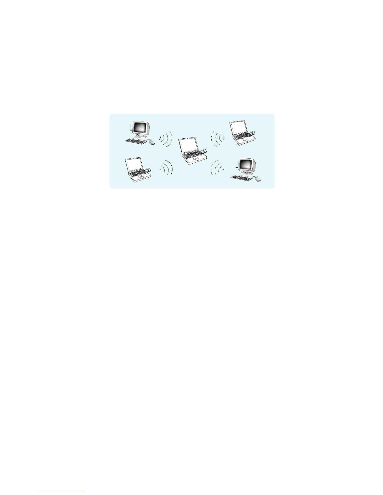
1.2.1 Access Point
WL-3553 provides software Access Point function for users can create the wireless network easily,
as they knew. In this function, it is not just a client anymore. All the wireless clients can connect to
each other via the AP mode WL-3553. For SOHO and SMB users, they can save the money for buy
a WL-3553 to instead Access Point to work.
Software
Access Point
1.2.2 Infrastructure
The WL-3553 provides access to a wired LAN for wireless workstations. An integrated wireless and
wired LAN is called an Infrastructure configuration. A group of WL-3553 PC users and an Access
Point compose a Basic Service Set (BSS). Each WL-3553 PC in a BSS can talk to any computer in
the wired LAN infrastructure via the Access Point.
An Infrastructure configuration extends the accessibility of a WL-3553 equipped PC to a wired LAN,
and doubles the effective wireless transmission range for 2 WL-3553 PCs. Since the Access Point is
able to forward data within its BSS, the effective transmission range in an infrastructure LAN is
doubled.
The use of a unique ID in a BSS is essential. All WL-3553 equipped PCs configured without roaming
options in an independent BSS must be configured with a BSS ID corresponding to the WL-3553
used in the BSS. Check your WL-3553 for its BSS ID or use the Site Survey function on
Configuration Utility program to determine the BSS ID.
The Infrastructure Wireless LAN configuration is appropriate for enterprise-scale wireless access to
a central database, or as a wireless application for mobile users.
Infrastructure mode also supports roaming capabilities for mobile users. More than one BSS can be
configured as an Extended Service Set (ESS). The continuous network allows users to roam freely
within an ESS. All WL-3553 PCs or other IEEE 802.11b compliant wireless adapter within one ESS
must be configured with the same ESS ID and use the same radio channel.
Before enabling an ESS with roaming capability, choosing a feasible radio channel and optimum
Access Point position is recommended. Proper Access Point positioning combined with a clear radio
signal will greatly enhance performance.
Page 7
3
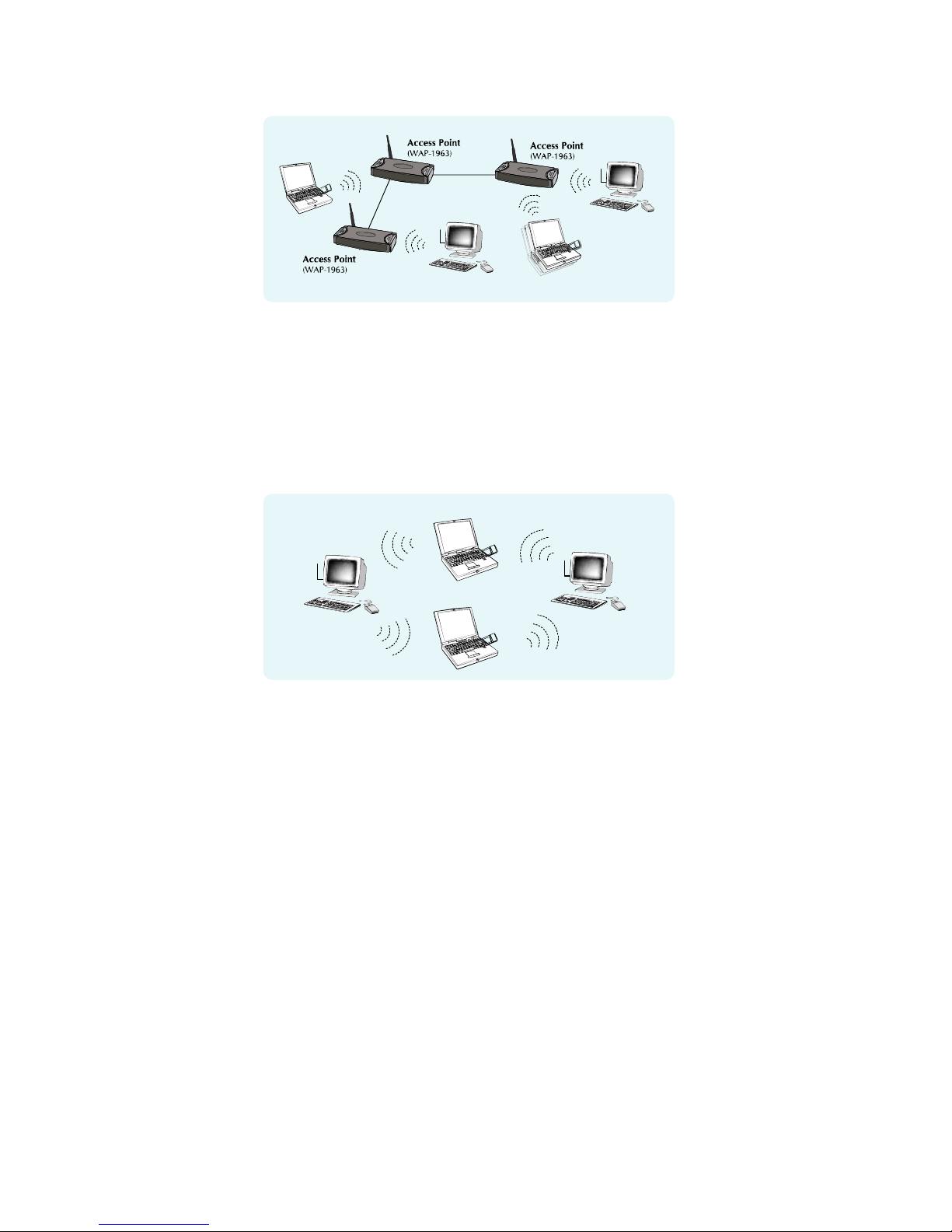
1.2.3 Ad-Hoc
An Ad-Hoc wireless LAN is a group of computers, each equipped with one WL-3553 adapter or other
wireless adapters, connected as an independent wireless LAN. Computers in a specific Ad-Hoc
wireless LAN must be configured to share the same radio channel.
Ad-Hoc wireless LAN configurations are appropriate for branch level departments or SOHO
operations.
(WL-3553)
(WL-3553)
WL-8303WL-8303
1.2.4 General Application
WL-3553 offers a fast, reliable, cost-effective solution for wireless client access to the network in
applications like these:
1. Remote access to corporate network information
E-mail, file transfer and terminal emulation.
2. Difficult-to-wire environments
Historical or old buildings, asbestos installations, and open area where wiring is difficult to
employ.
3. Frequently changing environments
Retailers, manufacturers and banks who frequently rearrange the workplace and change
location.
4. Temporary LANs for special projects or peak time
Trade shows, exhibitions and construction sites need temporary setup for a short time period.
Retailers, airline and shipping companies need additional workstations for a peak period.
Auditors require workgroups at customer sites.
5. Access to database for mobile workers
Page 8

4
Doctors, nurses, retailers, white-collar workers need access to database while being mobile in
the hospital, retail store or office campus.
6. SOHO (Small Office and Home Office) users
SOHO users need easy and quick installation of a small computer network.
7. High security connection
The wireless security network installs quickly and provides the flexibility to reconfigure easily.
1.3 Specification
Product Wire Free – 11Mbps Wireless LAN PCMCIA Adapter
Model Name WL-3553
Attach Interface PCMCIA Type II, CardBus
LED Indicators ACT, LNK
Operating Frequency / Channel 2.412~2.462GHz (FCC, Canada) / 11 Channels
2.412~2.4835GHz (TELEC, Japan) / 14 Channels
2.412~2.472GHz (ETSI, Europe) / 13 Channels
RF Modulation Direct Sequence Spread Spectrum (DSSS) Technology
(CCK, DQPSK, DBPSK)
RF Output Power 16dBm
Sensitivity -83dBm (@ PER<8%)
Data Rate 11, 5.5, 2, 1 Mbps with auto-rate fallback
Media Access Protocol CSMA/CA + ACK
Standard Antenna Build-in patch antenna
Range Up to 1100 feet outdoor and 350 feet indoor
Working Mode Ad-Hoc, Infrastructure, Access Point
Power Consumption TX: 3.3V, 340mA
RX: 3.3V, 160mA
Stand by / sleep mode: 3.3V, 20mA
Dimension (mm) 114*54*5 (L*W*H)
Humidity 0 ~ 90%, non-condensing (Operating and storage)
Temperature 0 ~ 55 degree C (Operating), -10~70 degree C(Storage)
Compatibility Windows 98, Me, 2000, XP, Server 2003 and Linux
Management Utility or Windows XP built-in management interface
STANDARDS COMPLIANCE
Electromagnetic Compatibility FCC Part 15 class B, CE Mark, ETSI 300 328
1.4 Package Contents
Before installation, please check the items of your package. The package should include the
Page 9

5
following items:
WL-3553 x 1
Quick Installation Guide x 1
Drivers and User’s Manual CD x 1
If any of the above items are missing, contact your supplier as soon as possible.
1.5 Minimum System Requirements
Before installation, please check the following requirements with your equipment.
• Operating System: Windows 98/Me/2000/XP/Server 2003 or Linux
• PC with CD-ROM drive
• One CardBus PCMCIA slot
1.6 Installation Considerations
l Please keep the number of walls and ceilings between the Access Point and clients. Each wall or
ceiling can reduce your wireless cover range form 3-90 feet. Position your Access points,
Residential Gateways, and computers so that the number of walls or ceilings is minimized.
l Building materials make a difference – A solid metal door or aluminum studs may have a negative
effect on range. Try to position Access Points, and computers with wireless adapters so that the
signal passes through drywall or open doorways and not other materials.
l Keep the wireless product away form electrical devices or appliances at least 3-6 foot, which may
generate extreme RF noise.
Page 10

6
Chapter 2 Installation Procedure
Before you proceed with the installation, it is necessary that you have enough information about the
Wireless PCMCIA Card. Use the Procedure described in below in this chapter to install under Windows
98/Me/2000/XP/Server 2003.
Note: If you ever install the other Wireless Card before, please uninstall the existed driver and
utility first. If this is the first time to install this device, please refer to the following steps to
complete the installation.
2.1 Windows 98/Me/2000 Driver Installation
Note: The following installation operates under Window 2000. Procedures will be similar to
Windows 98/Me. About Windows XP/Server 2003 driver installation, please refer to next
section.
1. Plug WL-3553 into your PC’s PCMCIA slot.
2. Power on the PC and insert Drivers and User’s manual CD into CD-ROM drive.
3. Windows will automatically detect this wireless card and ask the user to install driver. Please click
“Next”.
Page 11

7
4. Please select the first option and click “Next” to continue.
5. Select “Specify a location” and click “Next”.
6. You can click “Browse” to find the driver location. (Assume "E" is your CD-ROM drive, the driver
can be found in E:\Drivers\WL-3553\Win2000). Please click “OK” to continue.
Page 12

8
7. Windows will show this screen to prompt you that it found a driver for the device you are installing,
please click “Next” to continue.
8. Windows 2000 may tell you this driver doesn’t contain Microsoft digital signature. Don’t worry
about this; Pleaser click “Yes” to continue the installation.
Page 13

9
9. Please click “Finish” to complete the driver installation.
(For Win98/Me, Windows will ask you to restart your PC when driver installation finished.)
2.2 Windows XP/Server 2003 driver installation
Note: The following installation operates under Window XP. Procedures will be similar to
Window Server 2003.
1. Plug WL-3553 into your PC’s PCMCIA slot.
2. Power on the PC and insert Drivers and User’s manual CD into CD-ROM drive.
3. Windows XP will detect WL-3553 and ask you to install driver. Please select the second option
and click “Next”.
4. Please select “Include this location in the search” and then click “Browse” to find out WL-3553
driver location to install driver. (Assume "E" is your CD-ROM drive, you can find out WL-3553
Page 14

10
driver in E:\Drivers\WL-3553\WinXP). Please click “Next” to continue.
5. WinXP will show you this dialog box to prompt you the driver has not passed Windows logo
testing, please press “Continue Anyway” to continue.
6. Please click “Finish” to complete the driver installation.
Page 15

11
2.3 Configuration Utility Installation
1. Run “setup.exe” under “E:\Utility\WL-3553\” directory, or click the “Start” button and choose “Run”.
When the dialog box appears, enter “E:\Utility\WL-3553\setup.exe” (Assume “E” is your CD-ROM
drive). You will see the dialog box as the picture. Please click “Next” to continue.
2. Then the utility will copy to your PC.
Note: After the utility installed, it will auto start. If the card is not working properly, you may
restart your PC. If the situation still exist after computer reboot, you should make sure that
your system has free resources.
Page 16

12
Chapter 3 Configuration Utility
The configuration utility is a powerful application that helps you configure the Wireless LAN Adapter
and monitor the link status and the statistics during the communication process.
After configuration utility installation finished, the configuration utility will automatically start. You can
find the icon in the system tray, please double click the icon to make further configuration. When
you are in Windows XP/Server 2003, you may see the dialog box as below. Please click “OK”.
Then you will see the configuration utility main screen. In order to use this utility to configure WL-3553,
please clear the “Windows Zero Config” option in the bottom of the screen. Windows XP and Server
2003 have provided a wireless configuration program for users to configure their wireless card without
install manufacturer’s utility. When wireless card installed, this program will auto start. If you want to use
our configuration utility to configure WL-3553, you have to disable the Windows built-in wireless
program (Windows Zero Config Service) firstly. Then you can use our utility to configure.
u Refresh: When you install two WL-3553s in your PC, you just need to install the utility once. If
you cannot see those cards, please click “Refresh”.
u Modes: WL-3553 has support Station Mode and Access Point Mode. Pleaser refers to Chapter 4
Station Mode and Chapter 5 Access Point Mode to know the detail settings.
u View: This option is use to enable/disable Status Bar.
u Help: This will show you the configuration utility version.
u Show Tray Icon: If you don’t want to see the icon in system tray, you may clear this option.
u Radio Off: When enable, WL-3553 will stop working.
u Windows Zero Config: Enable/disable Windows Zero Config Service.
u Close: Close configure screen. When click the icon in system tray, this screen will appear again.
Page 17

13
Chapter 4 Station Mode
4.1 General
In this option, you can check the current settings and the Signal Strength of the WL-3553.
4.2 Profile
In this option, you can check and modify the profiles.
u Add: When you want to add a profile manually, please click this bottom. Then you can see
the dialog box as below. Enter the settings as you want and click “OK” to save as a profile.
Page 18

14
Ø Profile Name: The name of this profile.
Ø Network Name (SSID): Shows and can be configured the SSID of the BSS that
willing to join.
Ø This is a computer –to-computer (ad hoc) network; wireless access points are
not use. : When you want this card to be a Ad-Hoc node. Please tick this option.
Ø Channel: Shows the number of the radio channel used for the networking. This
parameter is not active in the infrastructure operation mode.
Ø Data encryption (WEP enabled): You can tick this option for enabling WEP
function.
Ø Network Authentication (Shared mode): With this setting, allows communication
only with other devices with identical WEP settings.
Ø ASCII: When this option is selected. The WEP key format will be ASCII (American
Standard Code for Information Interchange, 0-9, a-z, A-Z). Otherwise, the WEP key
format will be HEX (Hexadecimal code, 0-9,a-f, A-F).
Ø Passphrase: You can enter the charters into the field. It will create the WEP keys
automatically.
Ø Key Length: Please select the WEP key Length. This option will function when the
Passphrase selected. You can decide the WEP key to 64bit or 128bit.
Ø Network Key: You can define the WEP (Wired Equivalent Privacy) Key values by
yourself.
Ø Confirm network key: Please enter the WEP key values again here.
Ø Key index (advanced): There are 4 keys available for the WEP function. Please
select one of them for WEP to operate.
Page 19

15
u Remove: Select a profile of the list and click this button, then the selected profile will be
deleted.
u Edit: Select the profile which you want to modify and click this button. Then you can change
the settings of the profile. After modification, please click “OK” to save.
u Duplicate: Select the profile which you want to copy and click this button. Configuration
utility will copy the profile and ask you to give a name for this profile.
u Set Default: If you want to set one of the profiles to be the first option which WL-3553 will
connected when your PC bootup. Please select the profile and click this button.
4.3 Available Network
This screen shows the APs or Adapters which available for WL-3553 to connect. When operating in
work mode “Any”, it will show the available APs and Adapters at the same time.
Click “ Refresh “ to collect the BSSID and Channel information of all the wireless devices around you.
If you wish to connect to any device on the “Available Network (s)” list, select the device on the list and
click “Add to Profile”, then you can see a dialog box as below, please click “OK”. WL-3553 will connect
to the selected device and create a profile for the selected device automatically.
Page 20

16
4.4 Advanced
In this option, you can have some advanced settings for WL-3553 working.
u Power Save: Shows Power Management modes. There are two optional selections for this
mode.
Ø None: Disable Power Save mode.
Ø Min: Enable the adapter in the power saving mode when it is idle, but some
components of the adapter is still alive. In this mode, the power consumption is larger
than “Max“ mode.
Ø Max: Adapter will enter power saving mode when it is idle.
Page 21

17
u Wireless Mode: You can select this card to work in which wireless standard. WL-3553 is
just support 802.11b.
u Preamble Mode: Preamble type defines the length of CRC block in the frames during the
wireless communication. “Short Preamble” is suitable for high traffic wireless network. “Long
Preamble” can provide more reliable communication.
u Channel Plan: Please refer to standard of your country to select the frequency domain.
When different frequency domain selected, the Channel number will also be changed.
u Data Rate: Select the Data Rate. There are 1 Mbps, 2Mbps, 5.5 Mbps, 11 Mbps, and Auto
mode. If Auto Mode is been selected, the device will select the best transfer rate
automatically.
u Fragmentation threshold: The size at which packets will be fragmented. Choose a setting
within a range from 256 to 2346 bytes.
u RTS Threshold: Minimum packet size to require an RTS (Request To Send). For packets
smaller than this threshold, an RTS is not sent and the packet is transmitted directly to the
WLAN. This is the option for the RTS Threshold activation.
u Save Log: When you feel the card works incorrect, you may save the Log file to your
provider to diagnostic.
u Set Default: The settings of this page will reset to default by click this button.
u Apply: After configure, please click this button to save the settings.
4.5 Status
In this option, you can check the current status of WL-3553.
Page 22

18
4.6 Statistics
In this option. You can get the real time information about the packet transmission and receiving
status.
Page 23

19
Chapter 5 AP Mode
5.1 General
In this option, you can see current SSID and BSSID of AP mode WL-3553. You may press the
“Config” button to configure WL-3553 as an AP for the wireless clients connected. If there are
some clients connect to AP mode WL-3553, you can see their information in the Association Table.
After click “Config” button, you can see the dialog box as below for the configuration of AP mode
WL-3553.
Page 24

20
5.2 Advanced
In this option, you can have some advanced settings for WL-3553 working.
u Beacon Interval: The interval of time that this access point broadcast a beacon. Beacon is
used to synchronize the wireless network.
u DTIM Period: Shows the client how often the beacon contains a delivery traffic indication
message. Input range is from 1 to 65535. By default, it is set to 3.
u Preamble Mode: Preamble type defines the length of CRC block in the frames during the
wireless communication. “Short Preamble” is suitable for high traffic wireless network. “Long
Preamble” can provide more reliable communication.
u Data Rate: Select the Data Rate. There are 1 Mbps, 2Mbps, 5.5 Mbps, 11 Mbps, and Auto
mode. If Auto Mode is been selected, the device will select the best transfer rate
automatically.
u Security:
Ø Open Authentication: With this setting, the station in the WLAN can receives and
transmits data from Access Point (null authentication).
Ø Shared Authentication: With this setting, allows communication only with other
devices with identical WEP settings.
Ø Both: With this setting, stations can communicate with the Access Point either with or
without data encryption. It will detect the AP that it connected is using which
Authentication mode and use the same mode to communicate.
u Set Defaults: The settings of this page will reset to default by click this button.
u Apply: After configure, please click this button to save the settings.
Page 25

21
5.3 Statistics
In this option. You can get the real time information about the packet transmission and receiving
status. You can click “Reset” button to clear the record to recount.
Page 26

22
Chapter 6 Frequently Ask Question
ü Why WAP-3000 and WL-3553 cannot work properly?
If you want the WAP-3000 to works with WL-3553, please fixed the data rate of WAP-3000 to
11Mbps. Because the WAP-3000 chipset and WL-3553 are not fully compatible, you need to
make this setting for them to connect each other.
ü How to create a new Ad-Hoc network with WL-3553?
If you want to create a new Ad-Hoc network with WL-3553, please add a new profile and
checked the setting “This is a computer-to-computer (ad hoc) network; wireless access points
are not used” of this profile. Then set this profile to default. When this setting is checked,
WL-3553 will work in Ad-Hoc mode. If unchecked, WL-3553 will work in Infrastructure mode.
ü Does AP mode WL-3553 work like a stand along Access Point?
Yes, AP mode WL-3553 is work likes a stand along Access Point when you use it to your
wireless network for the wireless clients to connected. When you run site survey function of your
wireless clients, you can find the AP mode WL-3553 and connected.
Page 27

23
Appendix
This section provides some technology document of IEEE802.11b. Read the description below to know
the standards about IEEE802.11b.
ü What is the IEEE 802.11b standard?
The IEEE 802.11b Wireless LAN standards subcommittee, which is formulating a standard for
the industry. The objective is to enable wireless LAN hardware from different manufactures to
communicate.
ü What IEEE 802.11 features are supported?
The product supports the following IEEE 802.11 functions:
• CSMA/CA plus Acknowledge protocol
• Multi-Channel Roaming
• Automatic Rate Selection
• RTS/CTS feature
• Fragmentation
• Power Management
ü What is Ad-hoc?
An Ad-hoc integrated wireless LAN is a group of computers, each with a WLAN adapter,
Connected as an independent wireless LAN. Ad-hoc wireless LAN is applicable at a
departmental scale for a branch or SOHO operation.
ü What is Infrastructure?
An integrated wireless and wired LAN is called an Infrastructure configuration. Infrastructure is
applicable to enterprise scale for wireless access to central database, or wireless application for
mobile workers.
ü What is BSS ID?
A specific Ad-hoc LAN is called a Basic Service Set (BSS). Computers in a BSS must be
configured with the same BSS ID.
ü What is WEP?
WEP is Wired Equivalent Privacy, a data privacy mechanism based on a 64/128 bit shared key
algorithm, as described in the IEEE 802.11b standard.
ü Can Wireless products support printer sharing?
Wireless products perform the same function as LAN products. Therefore, Wireless products
can work with Netware, Windows NT/2000/XP, or other LAN operating systems to support
printer or file sharing.
ü Would the information be intercepted while transmitting on air?
WLAN features two-fold protection in security. On the hardware side, as with Direct Sequence
Page 28

24
Spread Spectrum technology, it has the inherent security feature of scrambling. On the software
side, WLAN series offer the encryption function (WEP) to enhance security and Access Control.
Users can set it up depending upon their needs.
ü What is DSSS?What is FHSS?And what are their differences?
Frequency-hopping-spread-spectrum (FHSS) uses a narrowband carrier that changes
frequency in a pattern that is known to both transmitter and receiver. Properly synchronized, the
net effect is to maintain a single logical channel. To an unintended receiver, FHSS appears to be
short-duration impulse noise. Direct-sequence spread-spectrum (DSSS) generates a redundant
bit pattern for each bit to be transmitted. This bit pattern is called a chip (or chipping code). The
longer the chip, the greater the probability that the original data can be recovered. Even if one or
more bits in the chip are damaged during transmission, statistical techniques embedded in the
radio can recover the original data without-the need for retransmission. To an unintended
receiver, DSSS appears as low power wideband noise and is rejected (ignored) by most
narrowband receivers.
ü What is Spread Spectrum?
Spread Spectrum technology is a wideband radio frequency technique developed by the military
for use in reliable, secure, mission-critical communication systems. It is designed to trade off
bandwidth efficiency for reliability, integrity, and security. In other words, more bandwidth is
consumed than in the case of narrowband transmission, but the trade off produces a signal that
is, in effect, louder and thus easier to detect, provided that the receiver knows the parameters of
the spread-spectrum signal being broadcast. If a receiver is not tuned to the right frequency, a
spread –spectrum signal looks like background noise. There are two main alternatives, Direct
Sequence Spread Spectrum (DSSS) and Frequency Hopping Spread Spectrum (FHSS).
 Loading...