

Page 1

Web Hub
WH-2400M
WH-2400S
Web/SNMP Manageable Ethernet Hub
Page 2

Page 3

i
Trademarks
Copyright PLANET Technology Corp. 1998.
Contents subject to revision without prior notice.
PLANET is a registered trademark of PLANET Technology Corp. All
other trademarks belong to their respective owners.
FCC Warning
This device has been tested and found to comply with limits for a Class A
digital device, pursuant to Part 15 of the FCC Rules. These limits are
designed to provide reasonable protection against harmful interference
when the equipment is operated in a commercial environment. This
equipment generates, uses and can radiate radio frequency energy and, if
not installed and used in accordance with the user’s manual, may cause
interference in which case user will be required to correct the interference
at his own expense.
CE Mark Warning
This is a Class A product. In a domestic environment this product may
cause radio interference in which case the user may be required to take
adequate measures.
Reversion
User's manual for PLANET Web Hub
Models: WH-2400M / WH-2400S
Rev: 1.0 (Feb. 1998)
Page 4

Page 5

Table of Contents
CHAPTER 1. INTRODUCTION...........................................................1-1
About Web Hub ................................................................................1-1
Key Features ....................................................................................1-2
CHAPTER 2. HARDWARE OVERVIEW...............................................2-1
Front Panel Layout ...........................................................................2-1
Ports....................................................................................................... 2-2
LEDs...................................................................................................... 2-3
Common LEDs................................................................................... 2-4
Unit ID ................................................................................................... 2-5
Exclusive LEDs.................................................................................. 2-7
Rear Panel Layout.......................................................................... 2-11
CHAPTER 3. INSTALLATION............................................................3-1
Before You Begin.............................................................................. 3-1
Rack Mounting .................................................................................3-1
Star Topology................................................................................... 3-2
Star Cascading M-Link Ports................................................................... 3-2
Using the AUI Port.................................................................................. 3-3
Using the Console Port............................................................................ 3-3
Connecting Other Devices....................................................................... 3-3
Connecting Workstations .................................................................... 3-4
Connecting Switches ........................................................................... 3-5
CHAPTER 4. CONSOLE OPERATIONS ..............................................4-1
Software Setup..................................................................................4-1
Configuring the System........................................................................... 4-1
Terminal Program............................................................................... 4-1
Login Screen.....................................................................................4-5
Main Menu....................................................................................... 4-6
1. System Information Menu............................................................... 4-8
2. Management Setup Menu................................................................ 4-9
3. Device Control Menu.....................................................................4-15
4. User Authentication Menu .............................................................4-18
5. System Utility................................................................................4-20
CHAPTER 5. SNMP AND WEB MANAGEMENT: OVERVIEW................5-1
SNMP Management..........................................................................5-1
In-band................................................................................................... 5-2
Out-of-band ............................................................................................ 5-2
Managing from ....................................................................................... 5-2
SNMPc Platform ................................................................................. 5-2
Page 6

HP Overview Platform........................................................................ 5-2
Web Management................................................................................... 5-3
APPENDIX TECHNICAL SPECIFICATIONS...........................................A-1
Page 7

Introduction
WH-2400M / WH-2400S User's Manual
1-1A
Chapter 1
Introduction
About Web Hub
Web Hub is a versatile network solution with extensive management capabilities,
either through Console, Web or SNMP.
Web Hub’s (LRSC) Long Range Star Topology makes connecting networks
spread over large areas easy and convenient.
The LED Indicator Panel provides an effective means for monitoring the
network with extensive LED indicators for easy viewing ports Activity,
Utilization, Collision and other functions.
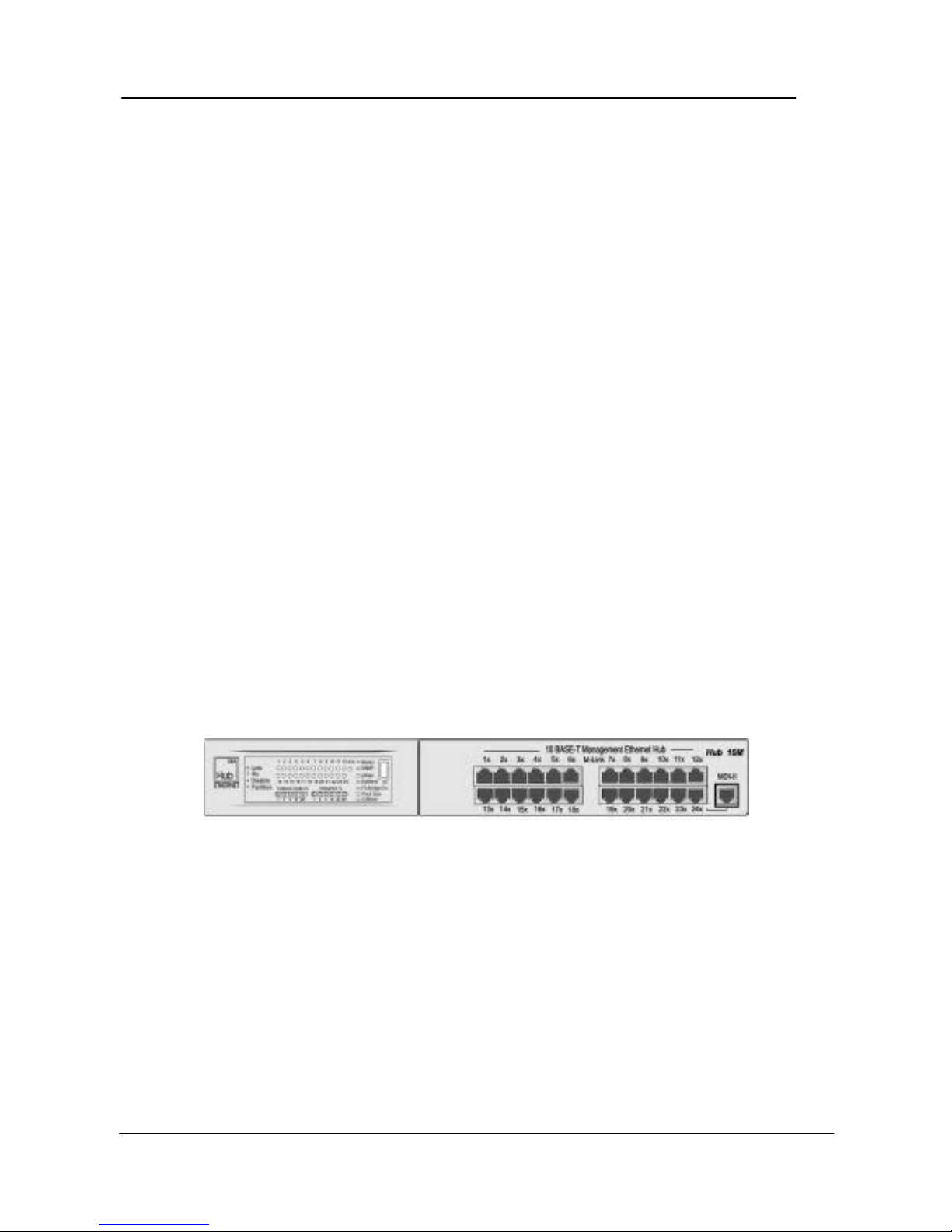
Figure 1.1 Web Hub WH-2400M/WH-2400S
WH-2400M
WH-2400S WH-2400S
Page 8

Introduction
PLANET Web Hub
1-2
Key Features
• 24 10Base-T (RJ-45) ports.
• 1-AUI Backbone port.
• Μemory for Network Management (WH-2400M only)
♦ Flash memory: 1MB
♦ EEPROM: 8KB
♦ DRAM: 2MB
♦ CPU: RISC CPU at 20MHz.
• (LRSC) Long Range Star Cascaded Hub Stack providing:
♦ More reliability than the conventional daisy-chain solutions
as any link failure affects the particular slave hub only, the rest
of the network continues to function and managed.
♦ Low per port management cost, as up to 208 ports (8 slaves)
can be managed by a single Master.
♦ Substantial saving in the cost of cabling as the slave hubs can
be distributed 100m away from the Master hub.
♦ Large network area coverage – 4 times that of any
conventional solution as the radius of the wiring area becomes
200m as against 100m with any other solution.
♦ Single link (UTP cable) for network and Mgmt. traffic
flowing separately.
• WEB Based Management
♦ Management from anywhere and any platform using a WEB
Browser.
♦ Complete web server embedded in device.
♦ Integrated HTML forms and Java applets for dynamic, real-
time status update and monitoring.
Page 9

Introduction
WH-2400M / WH-2400S User's Manual
1-3
♦ Standard web server security for total network protection.
♦ Easy-to-use familiar point & click interface.
♦ Photographic-Quality View to configure/monitor the device.
• SNMP Network Management
♦ Supporting standard RFC 1157 SNMP, RFC 1213 MIB-II, RFC
1516 Repeater MIBs, and PLANET proprietary MIBs.
♦ Supporting RFC 1757 RMON Groups 1,2,3 and 9.
♦ In-band/ ∗ Out-of-band management.
♦ Bootp server and TFTP software download supported.
♦ Console management via RS-232 (DB-9) port using a VT100
terminal/PC emulating terminal.
♦ Device Managers for Standard platforms such as HP- OpenView
and SNMPc.
• Extensive front panel LEDs viz. SNMP, WWW, Unit ID, Collision ratio,
Utilization ratio , FCS/Align, Runts, Late Collisions, Link, Disable, Rx,
Partition for complete status indication.
• Wide variety of ports including MDI-X, MDI-II uplink, and AUI (flexible
in future) backbone ports to facilitate easy network design and integration.
• Automatic Unit I.D. setting on all the hubs in the stack.
• Simple and Cost-effective upgrade by means of a WH-2400M master hub
to Switch 1000M swap, without losing on the port-level management.
• Unmatched price/performance – Value for money.
Page 10

Introduction
PLANET Web Hub
1-4
Page 11
Hardware Overview
WH-2400M / WH-2400S User's Manual
2-1
Chapter 2
Hardware Overview
This Chapter describes the hardware in detail, complete with illustrations of
every feature for a quick and easy understanding of Web Hub. The common
features of both the Master and Slave are described together and specific features
to each individual device are described separately.
Front Panel Layout
The Master Hub’s (WH-2400) front panel combines an LED Panel, 24 MDI-X
ports and an MDI-II port as shown in Fig. 2.1.
Figure 2.1 WH-2400M Font Panel.
Page 12
Hardware Overview
PLANET Web Hub
2-2
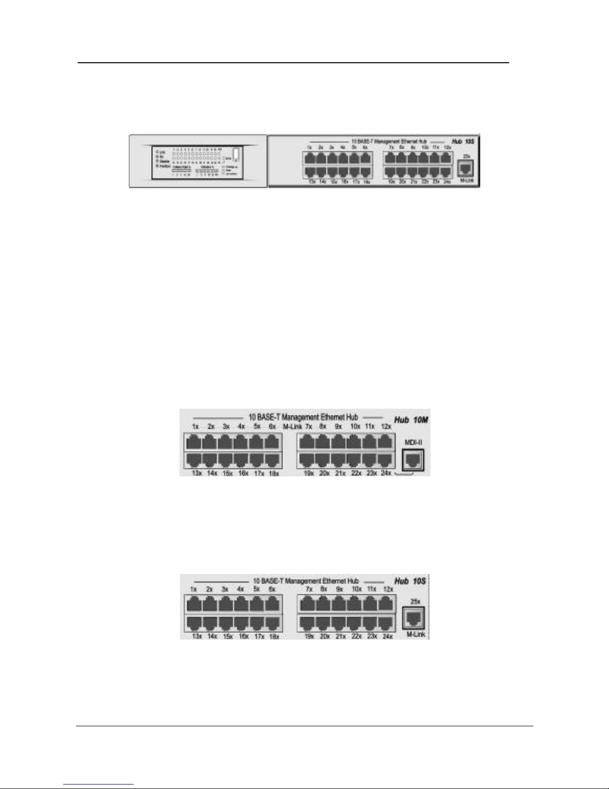
The Slave Hub’s (WH-2400S) front panel combines an LED Panel, 24 MDI-
X ports and an M-Link port as shown in Fig. 2.1.
Figure 2.2 WH-2400S Font Panel.
Ports
There are 25 10Mbps UTP ports on the front panel of both WH-2400M and WH2400S. In the case of WH-2400M ports 1~8 are shared M-Link ports for Uplink
Slave hubs (WH-2400S) network traffic. As well as Management traffic these
ports could also be used to connect workstations as any other MDI-X ports.
There is also an MDI-II interface port that is shared with Port 24 as shown in Fig.
2.3.
Figure 2.3 WH-2400M Ports.
In the case of WH-2400S there are 24 MDI-X ports and an M-Link port (MDI-II
Interface port) used for cascading to the Master hub as shown in Fig. 2.4.
Figure 2.4 WH-2400S Ports.
Page 13
Hardware Overview
WH-2400M / WH-2400S User's Manual
2-3
LEDs
The LED panels for both, WH-2400M and WH-2400S are a storehouse of
information, which visually indicate the physical connections, traffic flow,
Utilization, and Collision. The LED functions are described under Common
LEDs for those that are common to both WH-2400M and WH-2400S and
Exclusive LEDs for those are exclusive to either WH-2400M or WH-2400S.
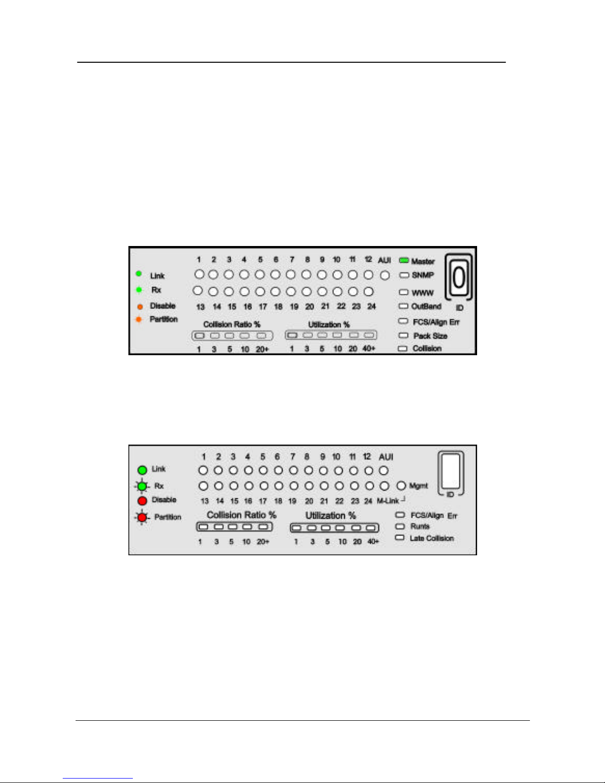
Fig. 2.5 illustrates the LED Panel for WH-2400M.
Figure 2.5 WH-2400M LED Panel.
Fig. 2.6 illustrates the LED Panel for WH-2400S.
Figure 2.6 WH-2400S LED Panel.
Page 14
Hardware Overview
PLANET Web Hub
2-4
Common LEDs
Most LEDs that are common to both WH-2400M & WH-2400S and are
explained in this section.
Port
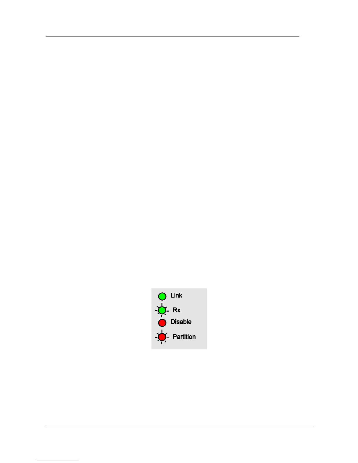
There is an LED for every port indicating the following status conditions of the
port. The legend located on the left of the ports LED shows the relationship
between the LEDs and the ports status at any given time.
• Link: The LED glows green in color indicating a link is up on any
particular port.
• RX: The LED blinks green in color indicating a port is receiving
data.
• Disable:The LED glows amber in color indicating a port has been
disabled by the administrator.
• Partition: The LED blinks amber in color indicating the port has been
partitioned OFF in the event of a malfunction.The LED goes
off as soon as the port has recovered.
Figure 2.7 LED Legend.
Page 15
Hardware Overview
WH-2400M / WH-2400S User's Manual
2-5
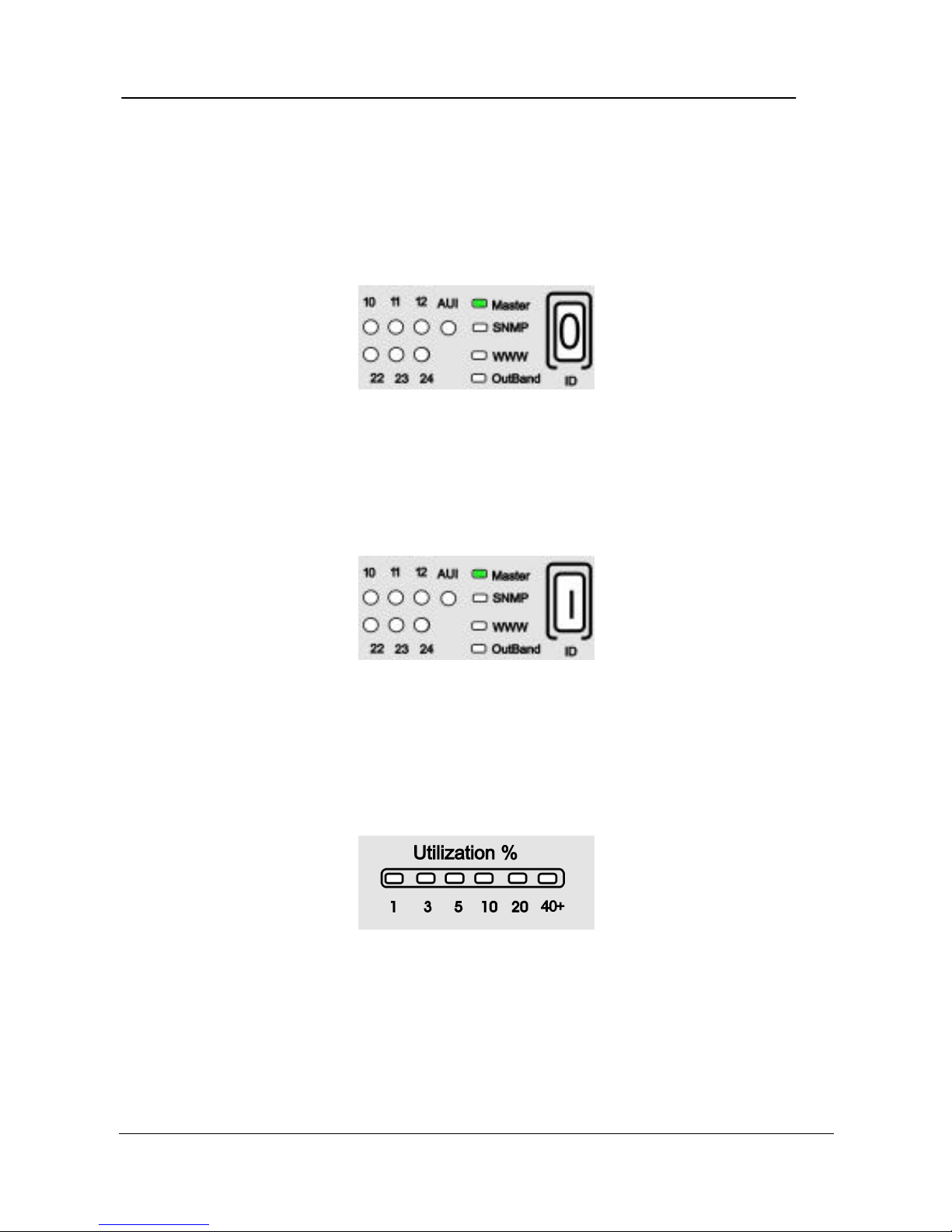
Unit ID
A Unit ID is automatically assigned to each hub in the stack as soon as the
machine boots up. The ID LED indicates the assigned Unit ID number. In a
stand-alone case, the ID number will be read as “0”.
Figure 2.8 WH-2400M ID LED.
When slave hubs are cascaded to the Master hub they are automatically assigned
the numbers 2~9, while the Master assumes ID “1”
Utilization %
The Utilization % LEDs indicate the usage percent of the network bandwidth. It
is dynamic in nature, changing with the bandwidth usage at any given time.
Figure 2.9 Utilization % LED.
Page 16
Hardware Overview
PLANET Web Hub
2-6
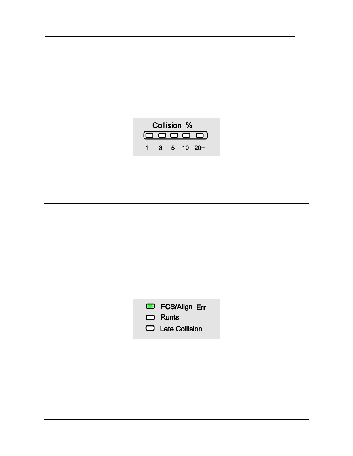
Collision Ratio %
The Collision % LEDs indicate the percentage of collision. Collisions occur
when two or more devices connected to a hub attempt to transmit data
simultaneously. When a collision occurs, the system aborts then transmits after a
random wait period.
Figure 2.10 Collision %.
The Collision percent can be calculated using the following formula.
Collision Ratio = (number of packets collided / number of packets transmitted) *
100.
FCS/Align Err
The FCS/Align Err LED glows, amber indicating there were corrupted packets
during transmissions. Alignment error occurs, when not all the bytes in a packet
are received.
Figure 2.11 FCS/Align LED.
Page 17
Hardware Overview
WH-2400M / WH-2400S User's Manual
2-7
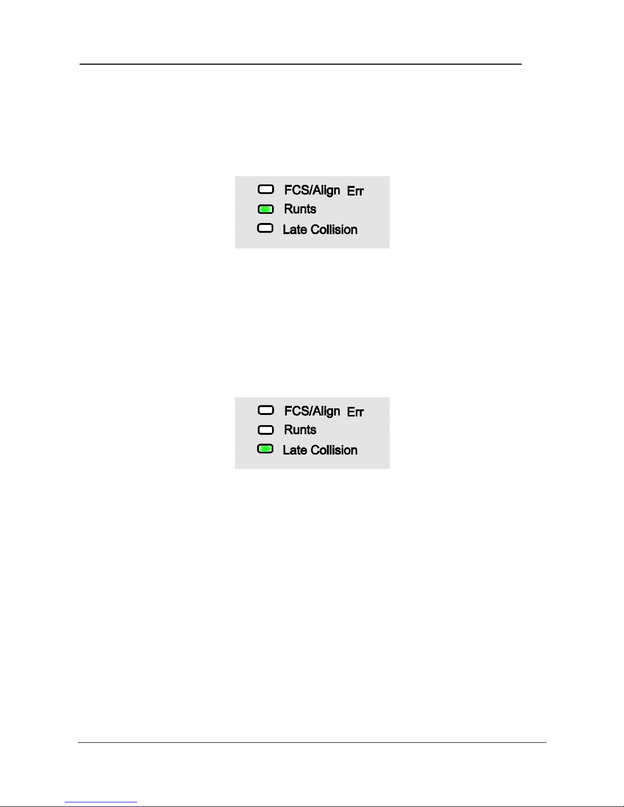
Runts
The Runts LED glows amber when the packets received are smaller than 64
bytes, the minimum valid Ethernet packet-size.
Figure 2.12 Runts.
Late Collision
The Late Collision LED glows, amber when collisions occur after 512 bits are
received causing an incomplete transmission.
Figure 2.13 Late Collision.
Exclusive LEDs
Some LEDs are exclusive to either WH-2400M or WH-2400S, their purpose is
described in this section.
Page 18
Hardware Overview
PLANET Web Hub
2-8
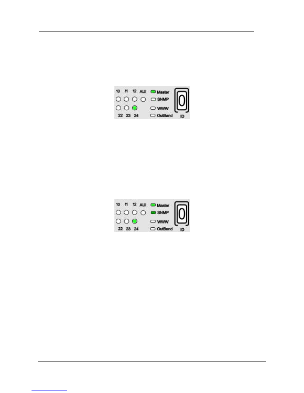
Master
The Master LED is exclusive to WH-2400M and glows green in color indicating
the hub is a Master hub. The LED at port 24 glows, green indicating the Uplink.
Figure 2.14 Master.
SNMP
The SNMP LED is exclusive to WH-2400M and glows green in color indicating
the hub is being monitored through the SNMP management program. The LED
at port 24 glows, green indicating the Uplink.
Figure 2.15 SNMP.
Page 19

Hardware Overview
WH-2400M / WH-2400S User's Manual
2-9
WWW
The WWW LED is exclusive to WH-2400M and glows green in color indicating
the hub is being monitored through the WWW management program. The LED
at port 24 glows, green indicating the Uplink.
Figure 2.16 WWW.
Out-Of-Band
The Out-Of-Band LED is exclusive to WH-2400M and glows green in color
indicating the hub is being monitored through the Console management program.
Figure 2.17 Out-Of-Band.
Page 20

Hardware Overview
PLANET Web Hub
2-10
M Link
This LED is exclusive to WH-2400S and glows green in color indicating that the
Slave is connected to one of the Master’s M-Link ports (1~8).
Figure 2.18 M-Link LED.
Mgmt
When a WH-2400S slave is connected to one of WH-2400M’s M-Link ports
(1~8) and is being managed through a management program, both WH-2400S’s
M-Link and Mgmt LEDs glows green in color.
Figure 2.19 Mgmt LED.
Page 21

Hardware Overview
WH-2400M / WH-2400S User's Manual
2-11
Rear Panel Layout
On WH-2400M’s rear panel there is an AUI port for linking to a backbone and a
Console Port (RS 232 Port) used in Out-Of-Band SNMP management.
Figure 2.20 HubWH-2400M Rear Panel.
On WH-2400S’s rear panel there is an AUI port for linking to a backbone.
Figure 2.21 HubWH-2400S Rear Panel.
Page 22

Hardware Overview
PLANET Web Hub
2-12
Page 23

Installation
WH-2400M / WH-2400S User's Manual
3-1
Chapter 3
Installation
Before You Begin
The hardware should be installed in a cool dry place. Leave at least 10 cm of
space around the hub for proper ventilation. In regards to power requirements,
Web Hub can operate in the input range of 100-240V AC.
Rack Mounting
Web Hub is 1.25U high and can be mounted in standard EIA 19” racks. Align
the mounting ears on the sides of the unit with the slot over the holes. Secure
screws tightly to fix the brackets to the device. Then place the device into the 19
inch rack and affix it with screws. Please ensure that the ventilation holes remain
unblocked.
Figure 3.1 Rack Mounting.
Page 24

Installation
PLANET Web Hub
3-2
Star Topology
The stack is built based on Star Topology, which offers the following advantages
over Daisy Chaining.
• Allows up to 8 Managed Slave hubs to be uplinked through ports 1~8.
• Maximum 100 meter segments allow very flexible physical configurations.
• Additional unmanaged hub can be linked to ports 9~24.
Star Cascading M-Link Ports
Figure 3.2 Star Topology.
Page 25

Installation
WH-2400M / WH-2400S User's Manual
3-3
Using the AUI Port
The AUI port located on the hubs rear panel is used to link to a backbone or to
integrate with a legacy LAN.
Figure 3.3 AUI Port.
Using the Console Port
Connect an RS 232 serial cable to the Console Port of WH-2400M and to a PC
or Notebook computer’s available COM port.
Figure 3.4 Console Port.
Connecting Other Devices
Other devices such as Workstations, Servers, Switches etc. can be easily be
connected to Web Hub.
Page 26

Installation
PLANET Web Hub
3-4
Connecting Workstations
Workstations can be connected to Web Hub’s Master or Slaves MDI-X Ports
(UTP Port) as shown in Fig. 3.5.
Figure 3.5 Connecting Workstations.
Page 27

Installation
WH-2400M / WH-2400S User's Manual
3-5
Connecting Switches
A Web Hub domain can be connected to switch as shown in Fig. 3.6.
Figure 3.6 Connecting Switches.
Page 28

Installation
PLANET Web Hub
3-6
Page 29

Console Operations
WH-2400M / WH-2400S User's Manual
4-1
Chapter 4
Console Operations
Software Setup
Web Hub’s internal software must be configured to enable its management
features. The first time, a minimal configuration must be done using the System
Console, thereafter further configuration, monitoring and other management can
be done several ways, including the System Console, Web Management and
SNMP management.
Configuring the System
To configure the system, connect an RS-232 serial cable to a COM port on a PC
or notebook computer and to the serial port of the Master Hub as show below.
Note: Do not use a null mode cable.
Figure 4.1 Connecting a PC via Console Port.
Terminal Program
Page 30

Console Operations
PLANET Web Hub
4-2
A Terminal Program is required to communicate with WH-2400M internal
software. Windows95 provides a suitable program called "HyperTerminal" and
is accessed from the Start menu. Click START, then Programs, Accessories and
then HyperTerminal.
Figure 4.2 Terminal Program.
An MS-DOS type terminal program can also make the connection with the
Master Hubs built in software, however this section describes using Windows
95s HyperTerminal.
From the HyperTerminal Screen double click the Hypertrm.exe icon.
Figure 4.3 Hypertrm.exe Icon
The Connection Description Screen is displayed. Type a name in the Name
panel to identify the connection, choose an icon (optional) and click OK.
Page 31

Console Operations
WH-2400M / WH-2400S User's Manual
4-3
Figure 4.4 New Connection Screen.
The following screen prompts for your country info, area code, telephone
number and the modem type. Since you won’t be dialing out via a modem you
only need to set the COM port. Click the arrow at the right of the “Connect
using” label.
Figure 4.5 Phone Number Screen.
Page 32

Console Operations
PLANET Web Hub
4-4
Select the correct COM port and press ENTER on the keyboard.
Figure 4.6 Selecting a COM port.
In the final screen all settings must be set correctly, Bits/sec “9600”, Data bits
“8”, Parity “None”, Stop bits “1” and Flow Control “Hardware” as in the figure
below. Click the OK button and the link to Web Hub will be complete.
Figure 4.7 Port Settings.
Page 33

Console Operations
WH-2400M / WH-2400S User's Manual
4-5
Login Screen
The login screen appears, similar to Figure 4.8. Enter the User Name and
Password (case sensitive). If there is no text in the Hyper Terminal screen at this
point, try entering the User Name and press Enter, the text should then appear.
The Error message “Input incorrect !!!! Press <Enter> to retry”, appears at
the bottom of the login screen if the Password or User Name is entered
incorrectly. Press ENTER to reset the User Name and Password fields to nothing
and enter them again making sure the spelling is correct. Press ENTER on the
keyboard to load the Main Menu.
WH-2400M/WH-2400S
W W EEEEE BBBBB H H U U BBBBB
W W W E EEE BBBB HHHH U U BBBB
W W EEEEE BBBBB H H UU BBBBB
User name [ I ]
Password [ ]
Figure 4.8 Main Banner of Run Time Local Consule Menu.
Page 34

Console Operations
PLANET Web Hub
4-6
Main Menu
The Main Menu Screen appears similar to Fig. 4.9 with 5 menu items.
Use the following keyboards keys to navigate through the menu and select a submenu. These keyboard commands are common to all menus.
• TAB KEY: Use the TAB key to select any of the six sub menus.
• ENTER KEY: Press the ENTER key after selecting a menu item with
the TAB key to view the selection’s sub-menu.
• EXIT: Return to the previous menu.
• HELP: Select HELP, to view keyboard commands.
WH-2400M/WH-2400S
-Main Menu-
System Information
Management Setup
Device Control
User Authentication
System Utility
EXIT HELP
Use <Tab> key to select the item, and press the <Enter>...
Figure 4.9 Main Menu of Run Time Local Console.
Page 35

Console Operations
WH-2400M / WH-2400S User's Manual
4-7
Help Menu
The help menu explains additional keyboards commands that can be used
throughout the Console Program. Press ESC to return to previous menu.
WH-2400M/WH-2400S
-Help Menu-
<Ctrl>-Q : Invoke Help Menu
<Ctrl>-R : Refresh Screen
[Enter] : Confirm Input
[TAB] : Go to next Tabstop
<Ctrl>-Z : Go to next Tabstop
<Ctrl>-W : Go to previous Tabstop
<Ctrl>-S/<Ctrl>-A : Select/Toggle <FIELD> value
[ESC] TO GO BACK
Figure 4.10 Help Menu.
Page 36

Console Operations
PLANET Web Hub
4-8
1. System Information Menu
The System Information Menu provides version identification for the
hardware and software. The System Contact and System Location fields
can be customized, and saved. Use the following keyboard commands to
navigate the menu.
♦ SAVE: Saves the configuration settings without confirmation.
♦ EXIT: Exits up one menu level.
♦ TO MAIN MENU: Returns to the Main Menu Screen.
♦ HELP: Goes to the help screen.
WH-2400M/WH-2400S
-System Information Menu-
System Description: Intelligent Ethernet Hub10M
Product Version: V 1
BOOT ROM Version: V 2.1.1
System Software Version: V 2.1.1
Web-Page Version: V 2.1.1
System Object ID: 1.3.6.1.4.200.1...
System Up Time: 0 days 0 hr. 0 min. 0 sec.
System Contact: [ ]
System Name: [10Mbps Ethernet Hub ]
System Location: [ ]
System Manager: Web and SNMP
MIB Supported:
RFC 1213, RFC1215, RFC1516, PLANET proprietary MIB
SAVE EXIT TO MAIN MENU HELP
Figure 4.11 System Information Menu
Page 37

Console Operations
WH-2400M / WH-2400S User's Manual
4-9
2. Management Setup Menu
The Management Setup Menu has 5 sub-menus used to configure the
Network, Serial Port, SNMP, Trap, and Web.
• Network Configuration: Configure Network address’s.
• Serial Port Configuration: View serial port configuration.
• SNMP Community Setup: Configure community names and access.
• Trap Community Setup: Setup community trap address’s.
• Web Configuration: Enable or Disable Web access.
WH-2400M/WH-2400S
-Management Setup Menu-
Network Configuration
Serial Port Configuration
SNMP Community Setup
Trap Manager Community Setup
Web Configuration
EXIT TO MAIN MENU HELP
Use <Tab> key to select the item, and press the <Enter>...
Figure 4.12 Management Setup Menu of WH-2400M Console.
Page 38

Console Operations
PLANET Web Hub
4-10
a. Network Configuration
The Network Configuration Menu displays the configuration
settings and allows for new configuration settings. New settings can
be entered under the “New” column and saved without confirmation
by selecting SAVE and pressing Enter.
WH-2400M/WH-2400S
-Network Configuration Menu-
Network Interface: <1>
Interface Type:
MAC Address: 00-E0-95-00-00-06
Configuration: Current New
IP Address: 210.68.0.98 [210.68. 0.98]
Subnet Mask: 255.255.255.0 [255.255.255.0]
Default Gateway: 0.0.0.0 [0.0.0.0]
SAVE EXIT TO MAIN MENU HELP
Figure 4.13 Network Configuration Menu.
Page 39

Console Operations
WH-2400M / WH-2400S User's Manual
4-11
b. Serial Port Configuration
Serial Port Configurations menu displays the serial port
configuration. These settings are fixed as set through the Terminal
Program, discussed at the beginning of this chapter.
WH-2400M/WH-2400S
-Serial Port Configuration Menu-
Operation Mode: <CONSOLE>Mode
Baud Rate: 9600 Bps
Character Size: 8 Bits
Parity: N Parity
Stop Bits: 1 Bits
*** Fixed configuration, can not be changed. ***
EXIT TO MAIN MENU HELP
Figure 4.14 CONSOLE Mode Configuration Menu
Page 40

Console Operations
PLANET Web Hub
4-12
c. SNMP Community Setup
The SNMP Community Setup is used to enter and edit community
names and set their Access Rights and Status. To add a community
name, enter the new name in the Input panel, and press the TAB key
to highlight the Access Rights panel, use the arrow keys (or CTRL +
S) to set the Access Rights. Next press the TAB key to highlight the
Status panel and set the status. Select one of the following
commands:
♦ Add: Adds the new name entered in the Input panel.
♦ Delete: Deletes the name entered in the Input panel.
♦ Update: Updates the settings of the name entered in the Input
panel.
WH-2400M/WH-2400S
-SNMP Community Menu-
Index SNMP Community Name Access Right Status
---------- --------------------------------- ------------------ --------------1 public <Read Only> <Disable>
2 private <Read/Write> <Enable>
3
4
5
6
------- ------------------------------ ----------------- ------------Input: [ ] <Read Only> <Disable>
ADD DELETE UPDATE EXIT TO MAIN MENU HELP
Figure 4.15 SNMP Community Configuration Menu
Page 41

Console Operations
WH-2400M / WH-2400S User's Manual
4-13
d. Trap Manager Community Configuration
Menu
WH-2400M/WH-2400S
Trap Manager Community Menu - 1
Index Trap Manager Community Name IP Address Status
---------- ------------------------------------------- -----------------...-------------1 [0.0.0.0] <Inactive>
2 [0.0.0.0] <Inactive>
3 [0.0.0.0] <Inactive>
4 [0.0.0.0] <Inactive>
5 [0.0.0.0] <Inactive>
6 [0.0.0.0] <Inactive>
***Use <Tab> or arrow keys to select index <Enter> to EDIT***
EXITTO MAIN MENU HELP
Figure 4.16 Trap Manager Community Configuration Menu
Page 42

Console Operations
PLANET Web Hub
4-14
e. Web Configuration
The Web Configuration can be enabled or disabled and determine
whether Web Management can be implemented. Press Ctrl + S keys
to toggle between Enable/Disable. Save the new setting.
♦ Enable: Web Management is enabled.
♦ Disable: Web Management is disabled.
WH-2400M/WH-2400S
-Web Configuration Menu-
Web Management Function: <Enable>
SAVE EXIT TO MAIN MENU HELP
Figure 4.17 Web Configuration Menu
Page 43

Console Operations
WH-2400M / WH-2400S User's Manual
4-15
3. Device Control Menu
The Device Control Menu is used to view and or configure each hub and its
ports.
Repeater Group Control/Status menu item provides a menu for configuring
each hub in the stack, such as naming the hub, and setting administration
status.
Repeater Port Control/Status menu item provides a menu for configuring
each port of the selected hub, such as naming ports and and setting
administration status.
WH-2400M/WH-2400S
-Device Control Menu-
Repeater Group Control/Status
Repeater Port Control/Status
EXIT TO MAIN MENU HELP
Use <Tab> key to select the item, and press the <Enter>
Figure 4.18 Device Control Menu
Page 44

Console Operations
PLANET Web Hub
4-16
a. Repeater Group Control/Status
Group Number (Unit ID) refers to the hub ID, a hub ID number can
be entered via the keyboard or use Prev. Group, Next Group
commands.
♦ Prev Group/Next Group: Cycle through Hub ID numbers press
Enter when the desired hub ID is reached.
Group Admin. State can be set to Enable or Disable by pressing Ctrl
+ S to cycle the options.
A Device Name of up to 24 character can be entered to name the
selected hub. The Device Role panel displays a hub as Master or
Slave.
The new settings must be saved before taking effect.
WH-2400M/WH-2400S
-Repeater Group Control/Status Menu-
Group Number (Unit ID): [ 1 ]
----------------------------------------------Group Status: Operation
Group Admin. State: < Enable >
Device Serial Number: 00000000
Device Name: [ ]
Device Role: Master
PRE GROUP NEXT GROUP SAVE EXIT TO MAIN MENU HELP
Figure 4.19 Repeater Group Control/Status Menu
Page 45

Console Operations
WH-2400M / WH-2400S User's Manual
4-17
b. Repeater Port Control/Status
Repeater Port Control/Status menu is used to view the status and
configure the ports of the hubs in the stack. Select the Hub ID in the
Group Number panel, then select the Port Number.
The Port Status will be displayed and Port State and Port Name can
be configured for ports that are Link Up or Link Down.
WH-2400M/WH-2400S
Repeater Port Control/Status Menu
>>Group Number: [ 1 ] Port Number: [ 1 ]
---------------------------------------------------------------------------Port Status:
Link: Link Up / Link Down
Link Polarity: Normal / Reversed
Auto Partition: Not Partitioned / Auto Partitioned
Interface Type: 10Base / AUI / UpLink
Operation Status: Yes
Port State:
Link Test < Enable >
Auto Polarity Reversal Enable
Administrator State < Disable >
Port Name: [ ] (max 8 bytes)
PRE GROUP NEXT PORT PRE GROUP NEXT GROUP SAVE EXIT TO MAIN MENU HELP
Figure 4.20 Repeater Port Control/Status Menu
Page 46

Console Operations
PLANET Web Hub
4-18
4. User Authentication Menu
User Name, Passwords and Privilege can be added, deleted and updated
through the User Authentication menu and sub menu.
Highlight the desired Index number and press Enter to bring up the sub
menu. Through the sub menu edit, add and update the system with up to six
user logon configurations.
♦ User Name: Up to 12 characters and case sensitive.
♦ Password: Up to 6 characters and case sensitive.
♦ Privilege: Read/Write or Read Only.
WH-2400M/WH-2400S
User Authentication Menu
Index User Name Password Privilege
-------- ------------- ----------- ----------1 [HUB10] [*****] Read/Write
2 [GUEST] [*****] Read Only
3
4
5
6
***Use <Tab> key to select the item, and press the <Enter>***
SAVE EXIT TO MAIN MENU HELP
Figure 4.21 User Authentication Menu
Page 47

Console Operations
WH-2400M / WH-2400S User's Manual
4-19
a. User Authentication Sub-Menu
Enter a new User Name and Password configuration or edit an
existing configuration and set the Privilege status.
♦ User Name: Up to 12 characters and case sensitive.
♦ Password: Up to 6 characters and case sensitive.
♦ Read/Write: User can logon with Read and Write privileges.
♦ Read Only: User can logon with Read Only privileges.
♦ Add: Use the Add command for new User configuration.
♦ Update: Use the Update command when editing existing
configurations.
♦ Delete: Use delete to remove a configuration.
WH-2400M/WH-2400S
User Authentication Menu - 1-
User Name Password Privilege
------------- ----------- ----------[HUB10] [*****] Read/Write
***Use <Tab> key to select the item, and press the <Enter>***
ADD DELETE UPDATE EXIT TO MAIN MENU HELP
Figure 4.22 User Authentication Menu-1
Page 48

Console Operations
PLANET Web Hub
4-20
5. System Utility
The System Utility menu has 3 sub menus to download system software,
restart the system and reset to factory settings.
• System Download: This utility can be used to download upgrade versions
of the system software should they become available.
• System Restart: Restarts the system from the Console Program.
• Factory Reset: Resets all settings back to factory settings including user
name and password.
WH-2400M/WH-2400S
-System Utility Menu-
System Download
System Restart
Factory Reset
EXITTO MAIN MENU HELP
Use <Tab> key to select the item, and press the <Enter>...
Figure 4.23 System Utility Menu of Web Hub Local Console
Page 49

Console Operations
WH-2400M / WH-2400S User's Manual
4-21
a. System Download Menu
To download system files the Boot Server IP Address must be
known as well as the name and location of the files.
Press Crtl S to select “Bootp Request (so that an X appears in the
brackets). Enter the Boot Server IP Address, then select System
Software Download and enter the file name complete with the path.
Follow the same procedure for Web-Pages Database Information
Download.
Highlight SAVE and press enter to save the download settings.
WH-2400M/WH-2400S-System Download Menu
( ) Bootp Request
File Download Request:
Boot Server IP Address: [0.0.0.0]
( ) System Software Download
Filename: [c:\WHUB1.CDE ]
( ) Web-Pages Database Information Download
Filename: [c:\WH24.CDE ]
SAVE EXITTO MAIN MENU HELP
Figure 4.24 System Download Menu
The download will start after restarting the system. If a download is incomplete,
it may be necessary to do a Factory Reset, thereby loosing all custom settings.
Page 50

Console Operations
PLANET Web Hub
4-22
b. System Restart Menu
The system can be restarted “cold” or “warm” started. Use Crtl S to
toggle between the two settings and then select the EXECUTE
command and press Enter. The system will reload and the logon
screen will prompt for user name and password.
WH-2400M/WH-2400S
-System Restart Menu-
System Restart:< Cold Start >
EXECUTE EXIT TO MAIN MENU HELP
Figure 4.25 System Reset Menu
Page 51

Console Operations
WH-2400M / WH-2400S User's Manual
4-23
c. Factory Reset
The setting for Network Configuration is “Not Reset”, “Reset from
BOOTP” or “Reset to Factory Default”, use Ctrl + S to toggle the
settings.
User Authentication Configuration setting is “Not Reset” or “Reset to
Factory Default”, use Ctrl + S to toggle the settings.
All customized settings including passwords will be lost and
returned to the factory settings.
WH-2400M/WH-2400S
-Factory Reset Menu-
Network Configuration: <Not Reset >
Factory Default:
IP Address 0.0.0.0
Subnet Mask 255.255.255.0
Default Gateway 0.0.0.0
User Authentication Configuration: <Not Reset >
Factory Default:
User Name Password Privilege
------------- ----------- -----------HUB10 HUB10 Read/Write
EXECUTE EXIT TO MAIN MENU HELP
Figure 4.26 Factory Reset System Configuration Data
Page 52

Console Operations
PLANET Web Hub
4-24
Page 53

SNMP and Web Management: Overview
WH-2400M / WH-2400S User's Manual
5-1
Chapter 5
SNMP and Web
Management: Overview
SNMP Management
SNMP (Simple Network Management Protocol), is a protocol designed to give a
user the capability to remotely manage a computer network. The management
functions fall into four types:
• Configuration
Configuration Management is used to make the desired settings for
devices and their ports, such as naming them so that they can be
identified quickly and easily.
• Monitoring
Monitoring the Status of hubs and their ports is essential in order to
analyze and optimize overall network performance.
• Security
Security has several purposes such as protecting the
systems configuration from being inadvertently altered by
unknowledgeable users to safeguarding sensitive information from
unauthorized persons.
Page 54

SNMP and Web Management: Overview
PLANET Web Hub
5-2
• Failure
Failure Management is two-fold in nature, that is Prevention and
Correction.
♦ Prevention is preparing the system for possible problems before
they happen.
♦ Correction is the ability fix problems that can’t be prevented,
quickly as possible to minimize the disruption of the network.
In-band
In-band management is accomplished from within the network, that is, by any
device that is linked up, either by cable or through the web.
Out-of-band
Out-of-band management is accomplished through the Console Management
Program via the Console (serial) port and cannot be accomplished from within
the network.
Managing from
SNMPc Platform
HP Overview Platform
HP Overview Platform is Hewlett Packard’s management program.
Page 55

SNMP and Web Management: Overview
WH-2400M / WH-2400S User's Manual
5-3
Web Management
WH-2400M embedded web server integrates HTML forms and Java™ applets
for dynamic, real-time status update and monitoring and Standard Web Server
security for total network protection.
For a complete understanding of Web Management, see Web Hub Software
Manual.
Page 56

SNMP and Web Management: Overview
PLANET Web Hub
5-4
Page 57

Appendix A
WH-2400M / WH-2400S User's Manual
A-1
Appendix A
Technical
Specifications
Page 58

Page 59

Appendix A
WH-2400M / WH-2400S User's Manual
A-1
Models WH-2400M WH-2400S
Standards
Compliance
IEEE 802.3 10BASE-T & 10BASE-5 Ethernet
24 10BASE-T (RJ-45) ports
Number of Ports
8 M-Link master ports shared with ports 1~8
1 MDI-II Uplink port (RJ-45) shared with port 24
1 Console port (RS-232-C DB-9)
1 M-Link port
with MDI-II
Interface
Unit ID, Collision ratio, Utilization ratio, FCS/Align, Runts, and Late
Collision per unit, Link, Rx, Disable, & Partition per port
LED Display
Master, SNMP, WWW and Outband (console)
port
M-Link
Management
Topology
-Star Connection using M-Link ports on the master
-Up to 8 slave hubs per master on UTP media
Distributed slave hubs: 100 meters away from the master
Single link (UTP cable) for network and Mgnt. traffic, flowing
separately
-Automatic Unit I.D. assignment
Memory for
Network
Management
Flash memory: 1MB
EEPROM: 8KB
DRAM: 2MB
CPU: RISC CPU at 20MHz
N/A
Web Based
Management
-Complete web server embedded in device
-Integrated HTML forms and Java™ applets for dynamic, real-time
status update and monitor
-Standard web server security for total network protection
-Easy–to-use familiar point & click interface
-Photographic-quality views to configure/monitor the device
-Management form anywhere and any platform using a WEB
browser.
SNMP Network
Monitoring
-Supporting standard RFC 1157 SNMP, RFC 1213 MIB-II, RFC
1516 Repeater MIBs, and PLANET proprietary MIBs
-Supporting RFC 1757 RMON Groups 1,2,3, and 9 *
-In-band & Out-of-band management*
-Bootp server and TFTP software download supported
-Console management via RS-232 (DB-9) port using a VT-100
terminal/PC emulating a terminal
Power
Requirements
90-240 VAC, 50/60 Hz
Internal universal power supply
Environment Operating Temperature: 0°C to 50° C
Storage Temperature: -30° C to 60° C
Operating Humidity: 5% to 95% non-condensing
Safety
Regulations
CUL (UL & CSA), LVD
EMI Certifications CE Mark, FCC Class A, VCCI Class 1
Dimensions W x D x H: 440 x 221 x 56.5 mm (1.25 U height)
Weight 5.0 kg
Mounting Standard EIA19” rack mounting
Page 60

Appendix A
PLANET Web Hub
A-2
EMWH2400M/S
 Loading...