

Page 1
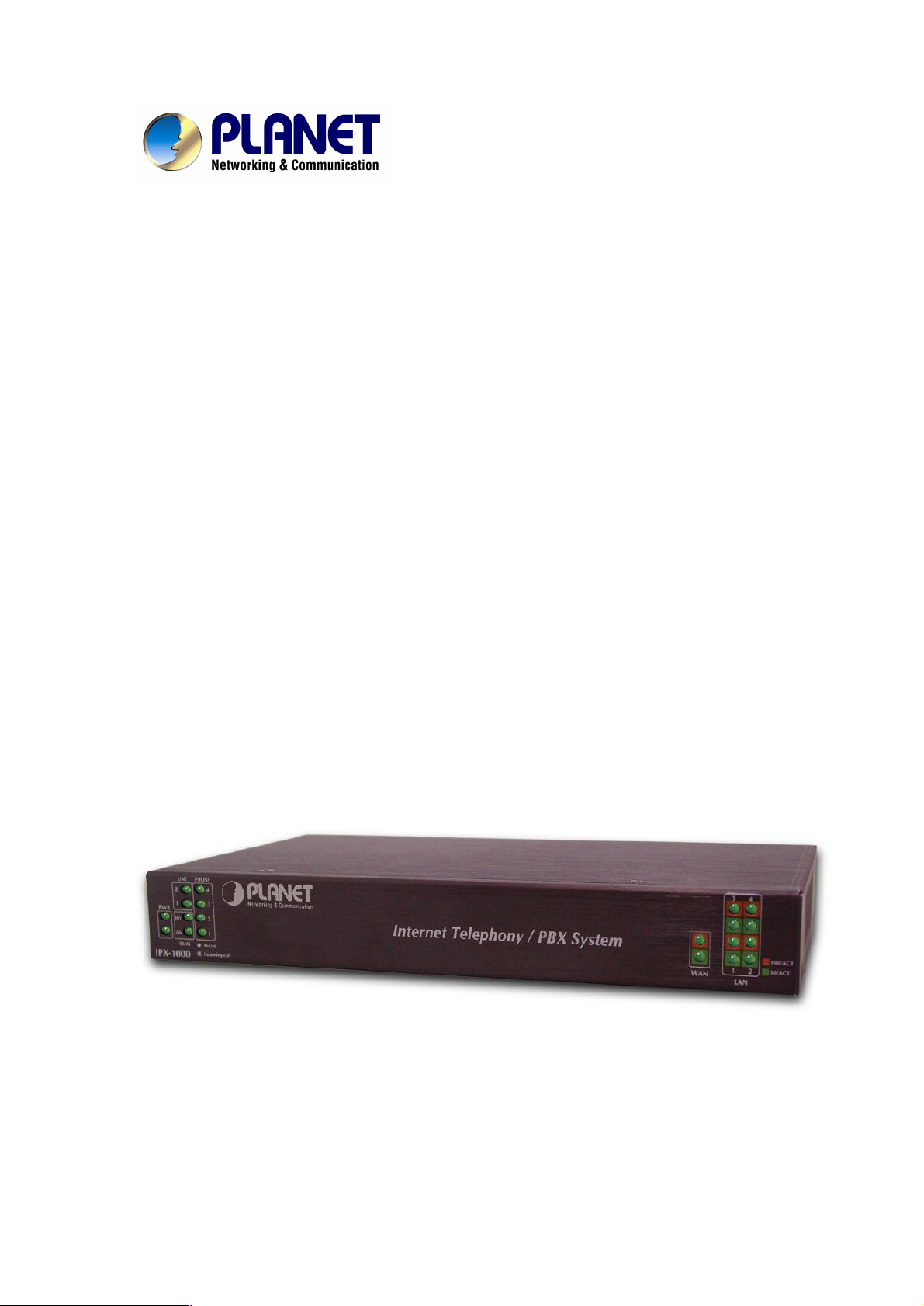
Internet Telephony /PBX System
IPX-1000
User’s manual
1
Page 2

Copyright
Copyright (C) 2004 PLANET Technology Corp. All rights reserved.
The products and programs described in this User’s Manual are licensed products of PLANET Technology, This
User’s Manual contains proprietary information protected by copyright, and this User ’s Manual and all
accompanying hardware, software, and documentation are copyrighted.
No part of this User’s Manual may be copied, photocopied, reproduced, translated, or reduced to any electronic
medium or machine-readable form by any means by electronic or mechanical. Including photocopying, recording,
or information storage and retrieval systems, for any purpose other than the purchaser's personal use, and without
the prior express written permission of PLANET Technology.
Disclaimer
PLANET Technology does not warrant that the hardware will work properly in all environments and applications,
and makes no warranty and representation, either implied or expressed, with respect to the quality, performance,
merchantability, or fitness for a particular purpose.
PLANET has made every effort to ensure that this User’s Manual is accurate; PLANET disclaims liability for any
inaccuracies or omissions that may have occurred.
Information in this User’s Manual is subject to change without notice and does not represent a commitment on the
part of PLANET. PLANET assumes no responsibility for any inaccuracies that may be contained in this User ’s
Manual. PLANET makes no commitment to update or keep current the information in this User ’s Manual, and
reserves the right to make improvements to this User’s Manual and/or to the products described in this User’s
Manual, at any time without notice.
If you find information in this manual that is incorrect, misleading, or incomplete, we would appreciate your
comments and suggestions.
CE mark Warning
The is a class B device, In a domestic environment, this product may cause radio interference, in which case the
user may be required to take adequate measures.
Trademarks
The PLANET logo is a trademark of PLANET Technology. This documentation may refer to numerous hardware
and software products by their trade names. In most, if not all cases, their respective companies claim these
designations as trademarks or registered trademarks.
Revision
User’s Manual for Internet Telephony PBX System
Model: IPX-1000
Rev: 1.0 (July 2004)
Part No. EM-IPX1000V1
2
Page 3

TABLE OF CONTENTS
Chapter 1 Introduction.........................................................................1
Overview.............................................................................................................1
Package Content................................................................................................2
Physical Details..................................................................................................2
LED Display & Button...................................................................................2
Physical Interfaces........................................................................................3
Chapter 2 Preparations & Installation.................................................4
Physical Installation Requirement....................................................................4
Administration Interface....................................................................................6
LAN/WAN Interface quick configurations......................................................6
Web configuration access:............................................................................6
Preparation before beginning web administration on IPX-1000....................8
Checking TCP/IP settings on Windows 95/98...............................................8
Checking TCP/IP settings on Windows NT.................................................10
Checking TCP/IP Settings - Windows 2000:...............................................13
Checking TCP/IP Settings - Windows XP...................................................15
LAN IP address configuration via web configuration interface....................17
WAN IP address configuration via web configuration interface...................17
Internet Access Setup.................................................................................18
Chapter 3 Network Service Configurations......................................20
Configuring and monitoring your IPX-1000 from web browser...................20
Overview on the web interface of IPX-1000................................................20
Manipulation of IPX-1000 via web browser.................................................20
LAN/WAN Configuration.............................................................................21
DHCP Server Configuration........................................................................26
Internet Sharing..........................................................................................27
Advanced Internet Configuration................................................................28
Firewall Configuration.................................................................................34
QoS Configuration......................................................................................35
DDNS.........................................................................................................38
VPN Configuration......................................................................................39
Chapter 4 Telephone Service Configurations...................................42
IPX-1000 Telephony Functions.......................................................................42
System........................................................................................................42
PBX Configuration......................................................................................43
Co/Extension line Configuration.................................................................47
Toll Table.....................................................................................................51
3
Page 4

H.323 Configuration....................................................................................51
Calling party configuration .................................................................................53
VoIP & PSTN..............................................................................................55
VoIP user....................................................................................................56
Appendix A: IPX-1000 Telephone Commands..................................58
Appendix B: Specifications...............................................................67
4
Page 5

Chapter 1
1
Introduction
Overview
IPX-1000 is a full function PBX system with extra built-in features like auto-attendant; voicemail, VoIP
(Internet Phone), and various network services. It provides a solid, uniform platform for both voice
communications as well as network communications. Built on state-of-the-art embedded technology,
IPX-1000 offers a seamlessly integrated solution for the telecommunication needs of modern times. Its
versatile and expandable design makes IPX-1000 an ideal choice for companies of small to medium
sizes.
PBX Functions
• IPX-1000 provides 6 analog ports to interface with 2 CO lines and 4 extension lines. Since all ports
are analog, no extra hardware is needed to connect analog devices.
• IPX-1000 allows the use of regular telephones instead of expensive digital telephones, resulting in
even more cost savings.
• IPX-1000 does not utilize the network for conventional telephony functions; therefore it adds no load
to the network and is not subject to network conditions/failures.
VoIP Functions
IPX-1000 provides two “H.323” VoIP resources as standard, VoIP functions are transparently
integrated with conventional telephony functions in the IPX-1000 design, and a uniform user interface is
provided for both conventional and VoIP functions.
Advanced Internet Functions
IPX-1000 provides advanced Internet service:
· DHCP server. Dynamic Host Configuration Protocol provides a dynamic IP address to PCs and
other devices upon request.
· PPPoE. The Internet (WAN port) connection supports PPPoE (PPP over Ethernet), as well as
Direct Connection type services.
· Virtual DMZ. The DMZ (DeMilitarized Zone) feature will allow un-restricted bi-directional traffic
passed through IPX, this will bring great convenience while configuring Internet applications
· Support VPN. Provides an easy-to-follow configuration interface to quickly setup the common VPN
deployment scenarios between each of the machines to minimize support requirements.
1
Page 6
Package Content
The contents of your product should contain the following items:
IPX-1000 unit
Power adapter
Quick Installation Guide
User’s Manual CD
RJ-45 cable x 1
RJ-11 cable x 1
Physical Details
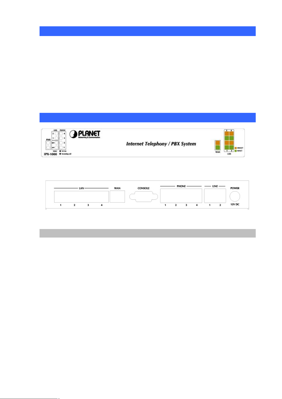
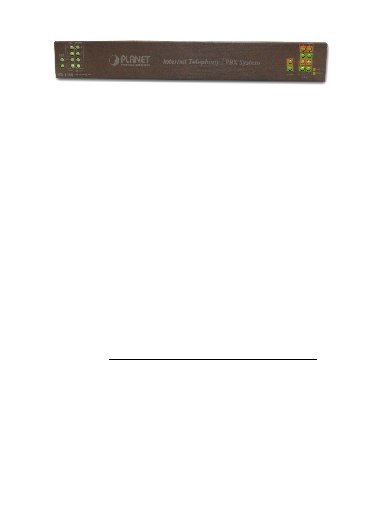
Front Panel of IPX-1000
LED Display & Button
Rear Panel of IPX-1000
2
Page 7

to a 10/100 Mbps Ethernet network / xDSL
Indicator Color Activity Indication
PWR
Green On Power is supplied to the gateway.
Ÿ 80V
Ÿ 24V
LAN
Ÿ 10/ACT
Ÿ 100/ACT
WAN
Ÿ 10/ACT
Ÿ 100/ACT
LINE
Voice Channels
1-2
PHONE
Voice Channels
1-4
Green On Line status diagnostic
Green
Orange
Green
Orange
Green Off
Green Off
On
On
On
On
On
Blinking
On
Blinking
Data is presented on LAN.
The gateway is connected to LAN.
Data is presented on WAN.
The gateway is connected to WAN.
The line is idle.
The line is being used.
The line is ringing.
The line is idle.
The line is being used.
The line is ringing.
Physical Interfaces
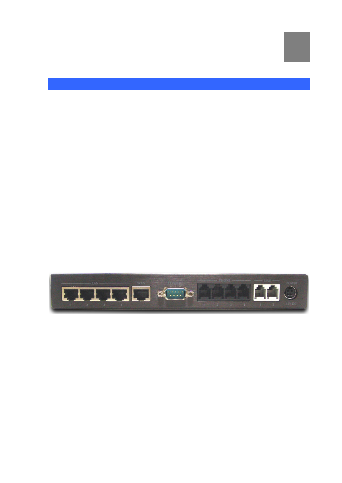
IPX-1000 is equipped with a WAN interface with 10/100 Mbps auto-negotiation capability, 4 LAN
Ethernet ports with 10/100 Mbps auto-negotiation, auto-MDI/MDI-X capability. In addition to the
LAN/WAN Ethernet interface ports, there is a 9-pin RS-232 interface port, four RJ-11 telephony
interface ports on the rear panel. Their functions are described below:
Port Label Function
RJ-45 LAN
RJ-45 WAN
9-pin RS-232 Console
RJ-11 (Line1~2) PSTN/CO line
RJ-11 (TEL1~4) Telephony
Connecting IPX to a 10/100 Mbps Ethernet network
Connecting IPX
/Cable modem for Internet access
Factory use.
Connected directly to the PSTN analog line/CO line.
Connected Telephone to PBX for voice communication
3
Page 8
Chapter 2
2
Preparations & Installation
Physical Installation Requirement
· Network cables. Use standard 10/100BaseT network (UTP) cables with RJ45 connectors.
· TCP/IP protocol must be installed on all PCs.
For Internet Access, an Internet Access account with an ISP, and either of a DSL or Cable modem
(for WAN port usage)
1. Choose an Installation Site
Select a suitable place on the network to install IPX-1000.
Ensure IPX-1000 and the DSL/Cable modem are powered OFF.
2.Connecting to LAN
Using UTP cables, connect all your LAN devices (PC, NB, HUB, switch…) to the LAN ports on the
IPX-1000. The corresponding “LAN” light(s) on the front panel will turn on. Wait a minute or two
for all LAN devices to establish links with the IPX-1000. The network related installation is now
complete and you should be able to access the Internet.
3. Connect WAN Cable
Connect the DSL or Cable modem to the WAN port on IPX-1000. Use the cable supplied with
your DSL/Cable modem. If no cable was supplied, use a standard cable.
Using a UTP cable, connect the LAN port on the ADSL/cable modem to the WAN port on the
IPX-1000. Turn on the ADSL/cable modem and make sure its READY light is on steadily. If the
READY light keeps blinking, contact your Internet service provider (ISP) and fix the problem
before going to the next step.
If the connection is made properly, the “WAN” light on the front panel will turn on.
4
Page 9
4.Connecting power
Connection of incorrect telephony devices to the telephony
. For example,
t 1 to
ë
• Plug the power supply into the IPX-1000.
• Plug the power cord into a power outlet. Three lights (“Power”, “24V”, and “80V”) on the front
panel will turn on, indicating that the system is up and running.
5. Check the LEDs
• The PWR LED should be ON.
• For each LAN (PC) connection, the LAN LNK/ACT LED should be ON (provided the PC is also
ON.)
• The WAN LED should be ON.
6. Connecting to the telephony devices
· Connecting to PSTN/CO line
Connect CO line(s) to IPX-1000’s line 1 and/or line 2. The “Line 1” and/or “Line 2” light(s)
on the front panel will turn on.
· Connecting to Telephone
Connect telephone(s) to Tel 1 ~ Tel 4 (Extension 1 ~ Extension 4)
Note
ports can cause permanent damage to the IPX
the PSTN line should NOT be connected to the Tel por
4 on IPX-1000.
5
Page 10
Administration Interface
In general cases, the LAN IP address is the default gateway
of LAN side workstations for Internet access, and the WAN
is the IP address for remote calling party
i
PLANET IPX-1000 provides GUI (Web based, Graphical User Interface) for machine management and
administration.
LAN/WAN Interface quick configurations
PLANET IPX-1000 comes with two defaults IP address, default LAN side IP address is “192.168.0.1”,
and default WAN side IP address is “172.16.0.1”. You may use any PC to connect to the LAN port of
IPX-1000 to start machine administration.
Hint
IP of IPX-1000
to connect with.
Web configuration access:
To start IPX-1000 web configuration, you must have one of these web browsers installed on computer
for web management
· Netscape Communicator 4.03 or higher
· Microsoft Internet Explorer 4.01 or higher with Java support
Default LAN interface IP address of IPX-1000 is 192.168.0.1. You may now open your web browser,
and insert http://192.168.0.1 in the address bar of your web browser to logon IPX-1000 web
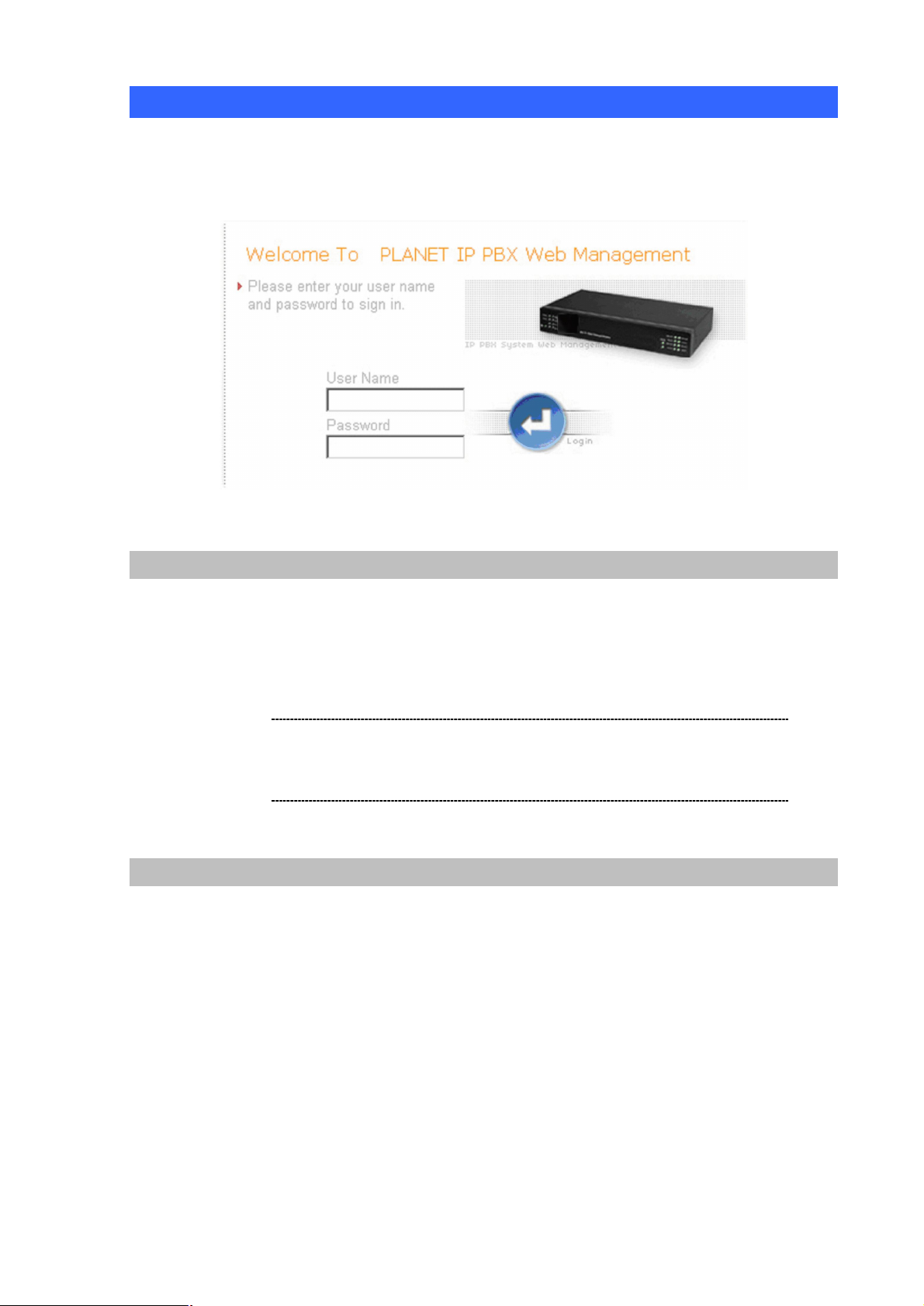
configuration page.
IPX-1000 will prompt for sign in User Name / Password, please enter: admin / 123 to continue machine
Web Management.
6
Page 11

Default WAN interface IP address of IPX-1000 is 172.16.0.1. You may now open your web browser, and
ë
TCP/IP, please refer to related chapter on user’s manual
CD or consult your network administrator for proper network
insert http://172.16.0.1 in the address bar of your web browser to logon IPX-1000 web configuration
page.
IPX-1000 will prompt for sign in User Name and Password, please enter: admin / 123 to continue
machine Web Management.
Note
Please locate your PC in the same network segment
(192.168.0.x) of IPX-1000. If you’re not familiar with
configurations.
7
Page 12
Preparation before beginning web administration on IPX-1000
In this section, we’ll introduce steps of how to setup a PC to communicate with IPX-1000 and Internet
access related parameters through TCP/IP protocol configuration.
Before starting web browser to connect to IPX-1000, please check TCP/IP configurations on PC: the
PC must be configured either as a DHCP client and or fixed IP allocation on the intranet or Internet.
After ensuring TCP/IP configuration on the managing workstation, you may connect to web
administration page of IPX-1000 either from intranet, or Internet
Following are guidelines of setting up TCP/IP configurations on different OS platform
Checking TCP/IP settings on Windows 95/98
If there is no TCP/IP installed on your Windows 95 or Windows 98, you must add the protocol and
change the settings on your PC.
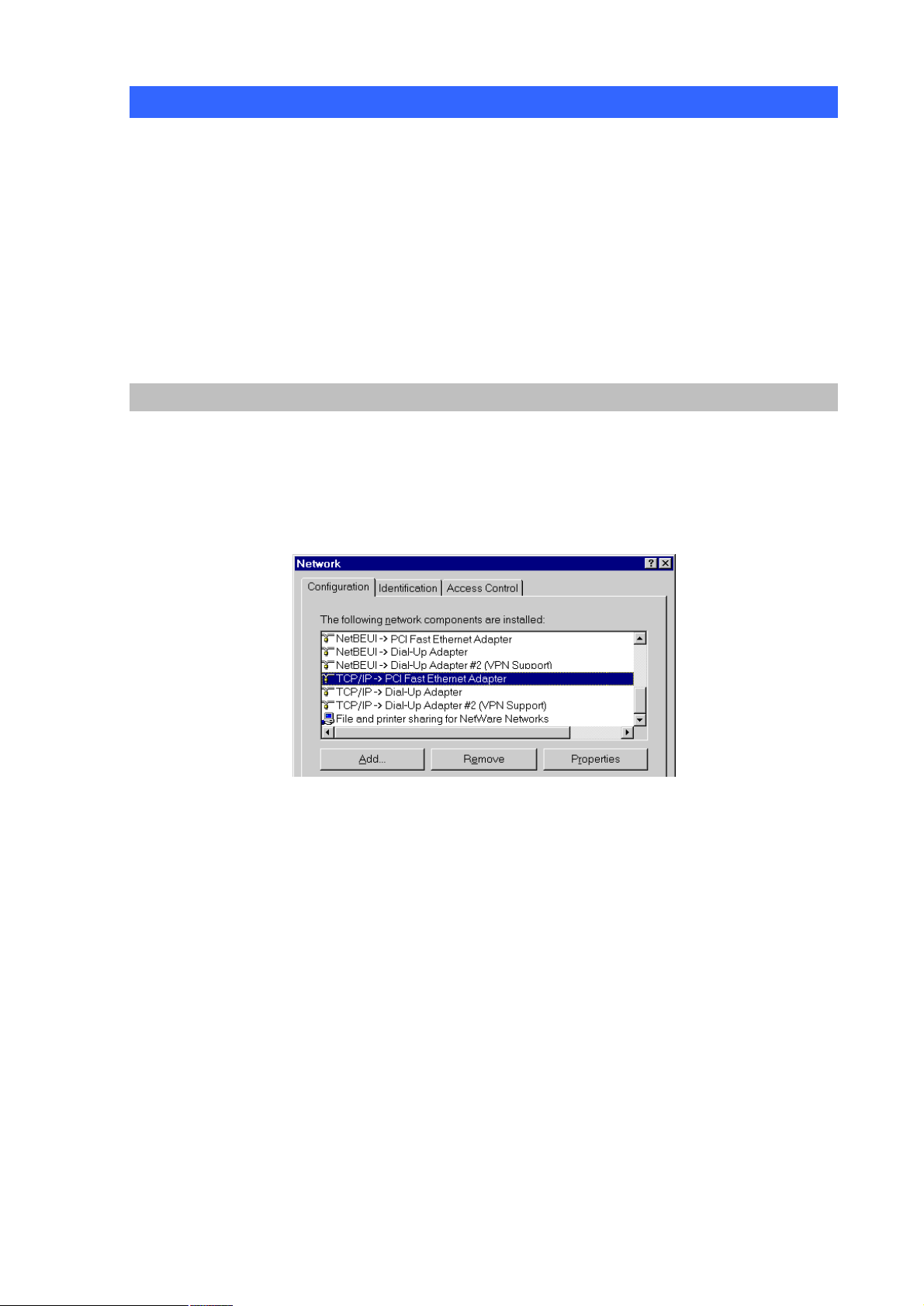
Step 1 Open the Control Panel, and double-clicking the Network icon. The Network window appears
Step 2 If TCP/IP protocol shown in the network window, please continue to the next step. If it is not
shown, please add TCP/IP protocol support as follows:
a. Clicking Add.
b. Double-clicking Protocol in the Select Network Component Type window, then the
Select Network Protocol window appears.
c. Choose Microsoft for the manufacturer.
d. Choose TCP/IP for the network protocol.
e. Clicking OK, and the Network window appears.
Step 3.1 Change the TCP/IP settings to use DHCP as follows (DHCP environment):
a. Double-clicking the first TCP/IP cable icon. The TCP/IP Properties window appears.
b. Verify that the IP Address tab has Obtain an IP address automatically selected and
that the IP Address and Subnet Mask fields are grayed out.
8
Page 13
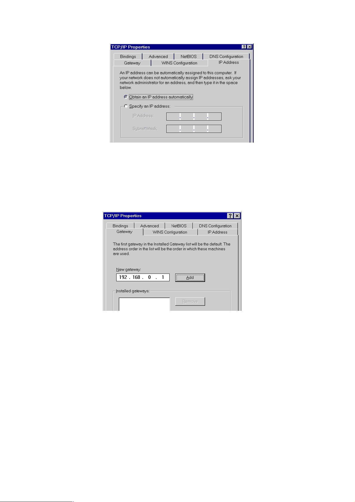
Step 3.2 Change the TCP/IP settings to use DHCP as follows (Fixed IP allocation):
If there is no DHCP server in your network, please consult your network administrator the
TCP/IP parameters of your PC, and insert the obtained data in IP address tab. To access
different IP segment (for example, from LAN to Internet), you will need to assign the
gateway and DNS (for Internet access) in your PC.
Step 4 Add the DNS server given to you by your ISP or network administrator:
a. Clicking the DNS Configuration tab.
b. Clicking Enable DNS.
c. Enter your host name in the Host field.
d. Enter your domain name in the Domain field.
e. Enter the IP address of the DNS server in the DNS Server Search Order field.
f. Clicking Add. The IP address displays in the window below the field.
9
Page 14

10
Step 5 Clicking OK, and reboot machine to make the modifications effective in your PC.
Checking TCP/IP settings on Windows NT
Obtain an IP address from a DHCP Server
Select Control Panel - Network, and, on the Protocols tab, select the TCP/IP protocol, as shown
below.
Windows NT4.0 - TCP/IP
a) Clicking the Properties button to see a screen like the one below.
Page 15
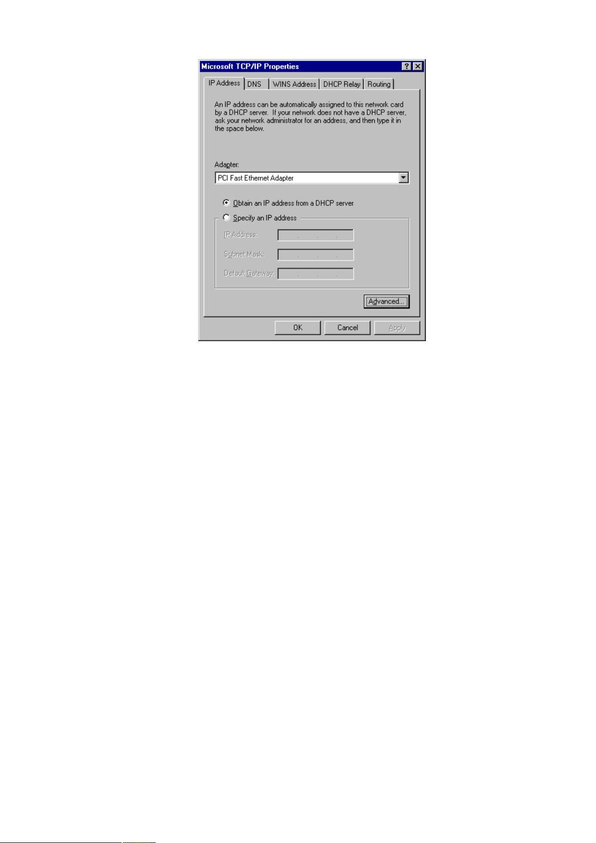
Windows NT4.0 - IP Address
b) Select the network card for your LAN.
c) Select the appropriate radio button - Obtain an IP address from a DHCP Server or
Specify an IP Address, as explained.
Specify an IP Address
If your PC is already configured with an IP address, check with your network administrator before
making the following changes.
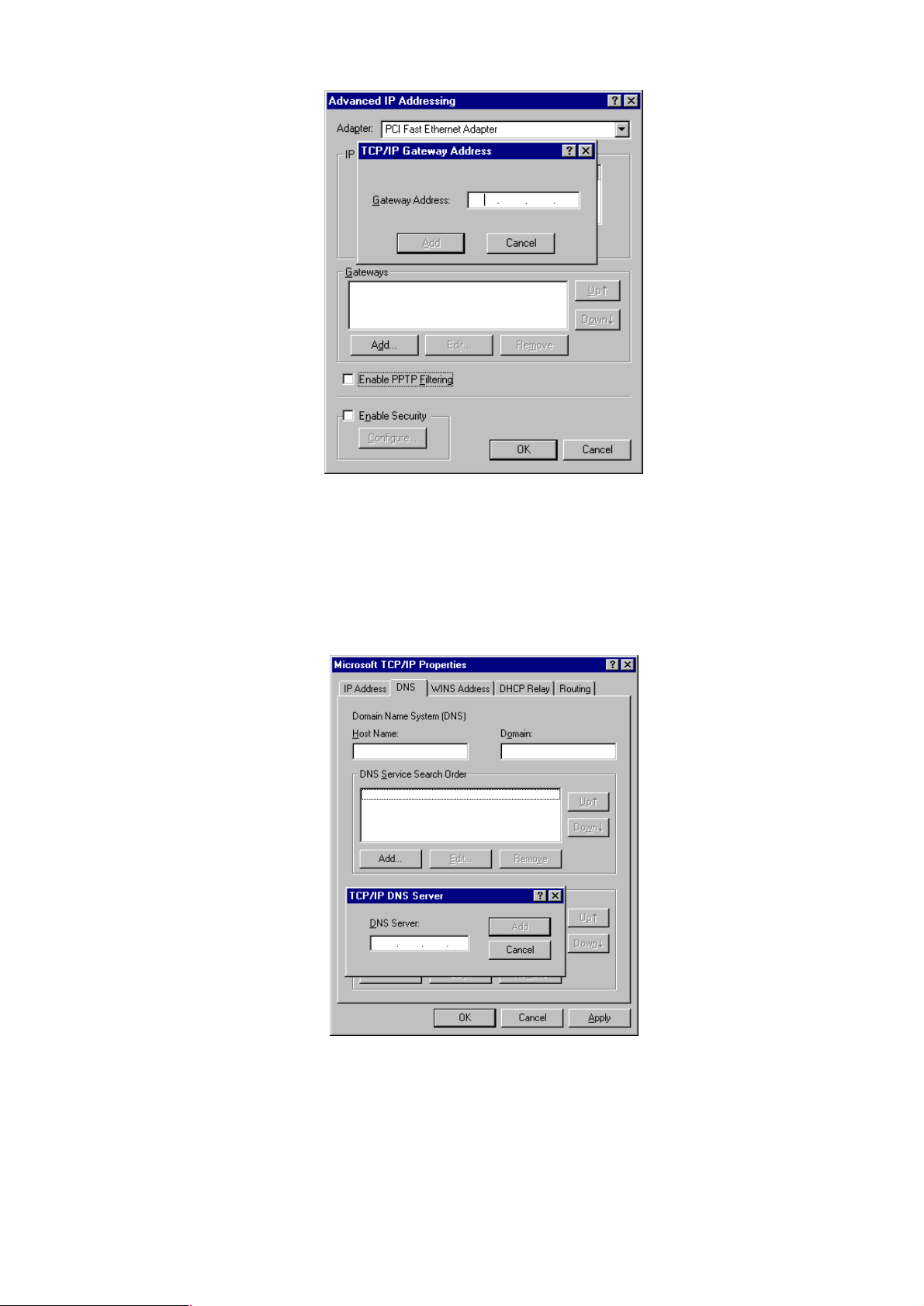
a) The Default Gateway must be set to match your network environment. To set this:
· Clicking the Advanced button on the screen above.
· On the following screen, clicking the Add button in the Gateways panel, and enter gateway IP
address, as shown below.
· If necessary, use the Up button to make the inserted on the first entry in the Gateways list.
11
Page 16
12
Windows NT4.0 - Add Gateway
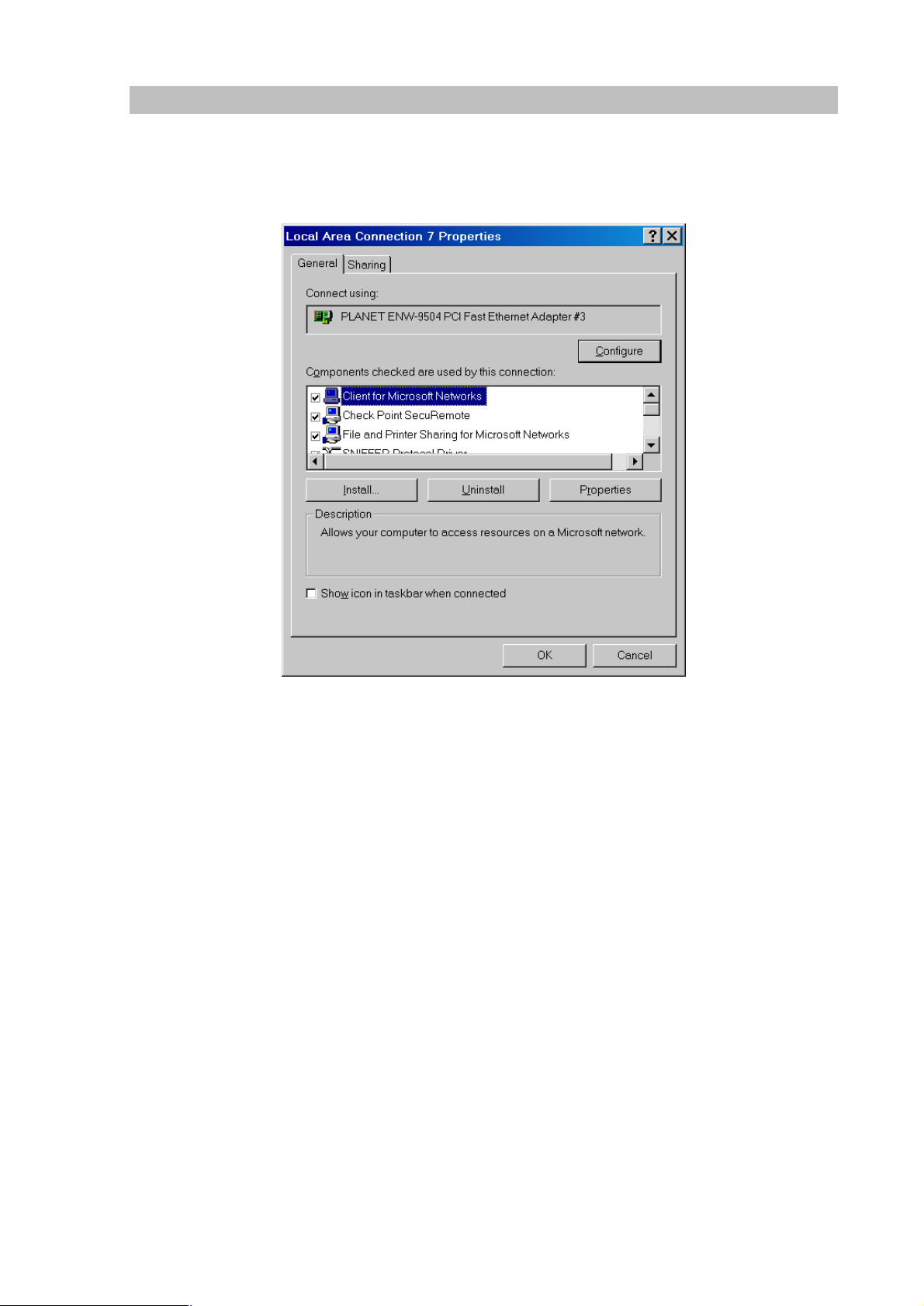
b) The DNS should be set to the address provided by your ISP, as follows:
· Clicking the DNS tab.
· On the DNS screen, shown below, clicking the Add button (under DNS Service Search Order), and
enter the DNS provided by your ISP.
Windows NT4.0 – DNS
Page 17
13
Checking TCP/IP Settings - Windows 2000:
Select Control Panel - Network and Dial-up Connection.
a) Right - clicking the Local Area Connection icon and select Properties. You should see a screen
like the following:
Network Configuration (Win 2000)
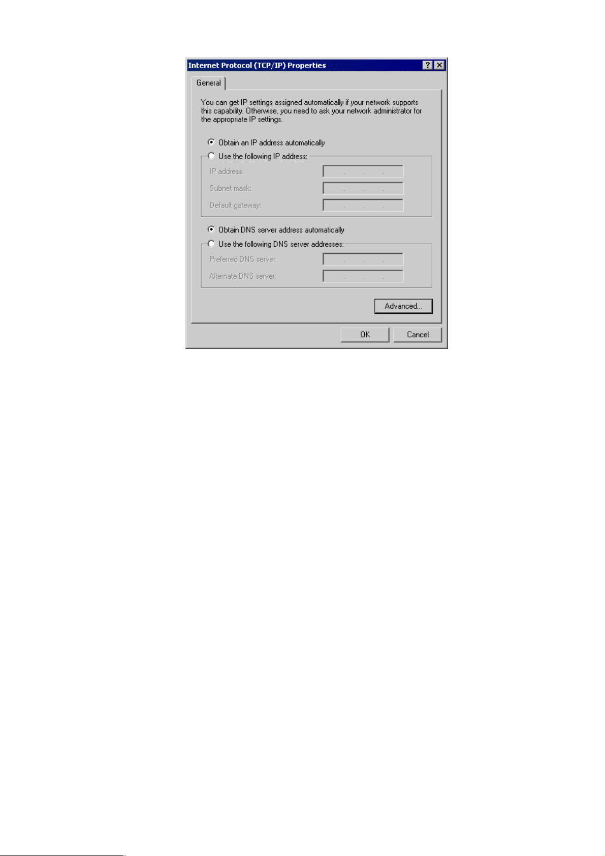
b) Select the TCP/IP protocol for your network card.
c) Clicking on the Properties button. You should then see a screen like the following.
Page 18
14
TCP/IP Properties (Win 2000)
Ensure your TCP/IP settings are correct with one of the following description.
Using DHCP
To use DHCP, select the radio button Obtain an IP Address automatically. This is the default Windows
setting. If your networking environment is a DHCP environment, Using this option is recommended.
Restart your PC to ensure it obtains an IP Address from DHCP server.
Using a fixed IP Address ("Use the following IP Address")
If your PC is already configured, check with your network administrator before making the following
changes.
· Enter gateway IP address obtained from network administrator in the Default gateway field and
clicking OK. If the DNS Server fields are empty, select Use the following DNS server addresses, and
enter the DNS address obtained from network administrator or addresses provided by your ISP,
then clicking OK.
Page 19

15
Checking TCP/IP Settings - Windows XP
Select Control Panel - Network Connection.
a) Right - clicking the Local Area Connection icon and select Properties. You should see a
screen like the following:
Network Configuration (Windows XP)
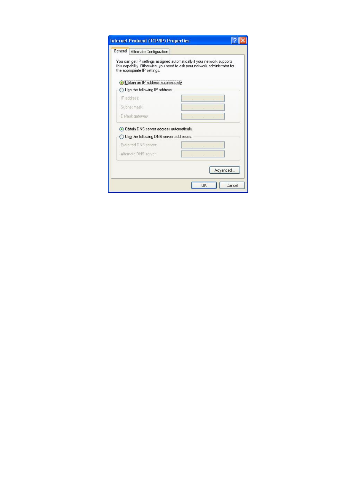
b) Select the TCP/IP protocol for your network card.
c) Clicking on the Properties button. You should then see a screen like the following.
Page 20
16
TCP/IP Properties (Windows XP)
Ensure your TCP/IP settings are correct with one of the following description.
Using DHCP
To use DHCP, select the radio button Obtain an IP Address automatically. This is the default Windows
setting. If your networking environment is a DHCP environment, Using this option is recommended.
Restart your PC to ensure it obtains an IP Address from DHCP server.
Using a fixed IP Address ("Use the following IP Address")
If your PC is already configured, check with your network administrator before making the following
changes.
Enter gateway IP address obtained from network administrator in the Default gateway field and clicking
OK. If the DNS Server fields are empty, select Use the following DNS server addresses, and enters the
DNS address obtained from network administrator or addresses provided by your ISP, then clicking
OK.
Page 21
17
LAN IP address configuration via web configuration interface
Execute your web browser, and insert the IP address (default: 192.168.0.1) of IPX in the adddress bar.
After logging on machine with username/password (default: admin / 123), browse to “LAN/WAN
Configuration” --> “LAN configuration” menu:
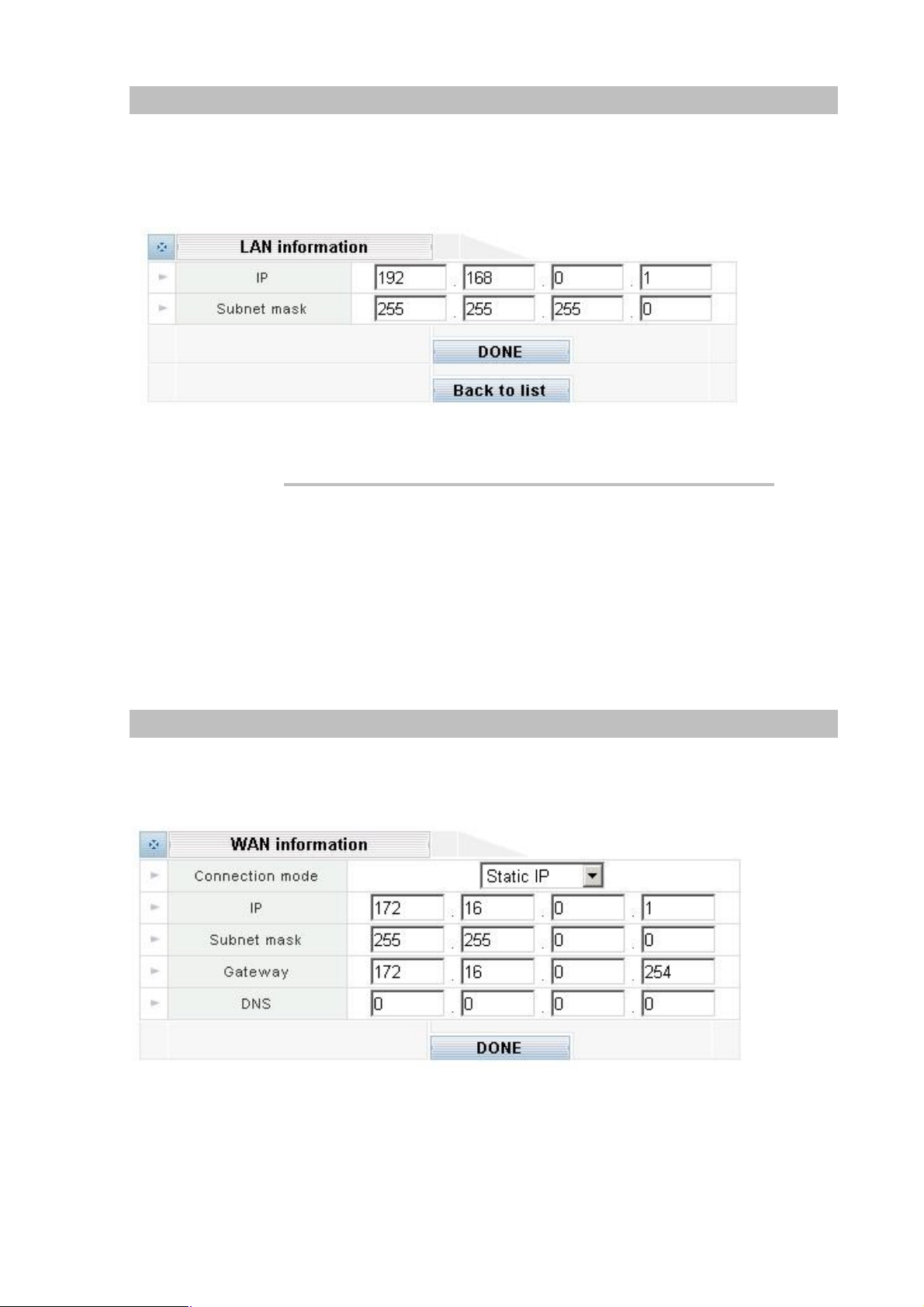
The LAN information Parameter Description of IPX-1000
IP LAN IP address of IPX-1000
Default: 192.168.0.1
Subnet mask LAN mask of IPX-1000
Default: 255.255.255.0
WAN IP address configuration via web configuration interface
Execute your web browser, and insert the IP address (default: 172.16.0.1) of IPX in the adddress bar.
After logging on machine with username/password (default: admin / 123), browse to “LAN/WAN
Configuration” --> “WAN configuration” menu, you will see the configuration screen below:
Page 22

18
Internet Access Setup
command from command prompt to get response from an Internet
i
Hint
· When WAN interface of IPX-1000 is properly configured, with default Windows TCP/IP settings, no
changes need to be made on LAN side PC for Internet access.
· If using a specified (fixed) IP address on your PC, refer to the user manual for details of the
required changes:
· The Gateway must be set to the IP address of IPX-1000
· The DNS should be set to the address provided by your ISP.
For Windows 9x/ME/2000
Ÿ Select Start Menu - Settings - Control Panel - Internet Options.
Ÿ Select the Connection tab, and clicking the Setup button.
Ÿ Select "I want to set up my Internet connection manually, or I want to connect through a local
area network (LAN)" and clicking Next.
Ÿ Select "I connect through a local area network (LAN)" and clicking Next.
Ÿ Ensure all of the boxes on the following Local area network Internet Configuration screen
are unchecked.
Ÿ Check the "No" option when prompted "Do you want to set up an Internet mail account
now?”
Ÿ Clicking Finish to close the Internet Connection Wizard.
Setup is now completed.
For Windows XP
Ÿ Select Start Menu - Control Panel - Network and Internet Connections.
Ÿ Select Set up or change your Internet Connection.
Ÿ Select the Connection tab, and clicking the Setup button.
Ÿ Cancel the pop-up "Location Information" screen.
Ÿ Clicking Next on the "New Connection Wizard" screen.
Ÿ Select "Connect to the Internet" and clicking Next.
Ÿ Select "Set up my connection manually" and clicking Next.
Ÿ Check "Connect using a broadband connection that is always on" and clicking Next.
Clicking Finish to close the New Connection Wizard. Setup is now completed.
To verify the Internet connection, you may start ping
node/site.
Page 23

19
onse from the remote site, please
is properly installed, LAN connection is OK, and
is not
working, or your PC's IP address is not compatible with
If your PC is using a fixed IP Address, its IP Address must
be within the range 192.168.0.2 to 192.168.0.254 to be
's default IP Address of
8.0.1. Also, the Network Mask must be set to
are on the
same network segment. (If you don't have a router, this
must be the case.)
i Hint
If you’re unable to get resp
check the following:
IPX-1000
it is powered ON.
You can test the connection by using the "ping" command:
ping 192.168.0.1
If no response is received, either the connection
IPX-1000's IP Address.
compatible with IPX-1000
192.16
255.255.255.0.Ensure that your PC and IPX-1000
Page 24
20
Chapter 3
3
Network Service Configurations
Configuring and monitoring your IPX-1000 from web browser
The IPX-1000 integrates a web-based graphical user interface that can cover most configurations
and machine status monitoring. Via standard, web browser, you can configure and check machine
status from anywhere around the world.
Overview on the web interface of IPX-1000
With web graphical user interface, you may have:
w More comprehensive setting feel than traditional command line interface.
w Provides user input data fields, check boxes, and for changing machine configuration settings
w Displays machine running configuration
To start IPX-1000 web configuration, you must have one of these web browsers installed on
computer for management
w Netscape Communicator 4.03 or higher
w Microsoft Internet Explorer 5.01 or higher with Java support
Manipulation of IPX-1000 via web browser
Log on IPX-1000 via web browser
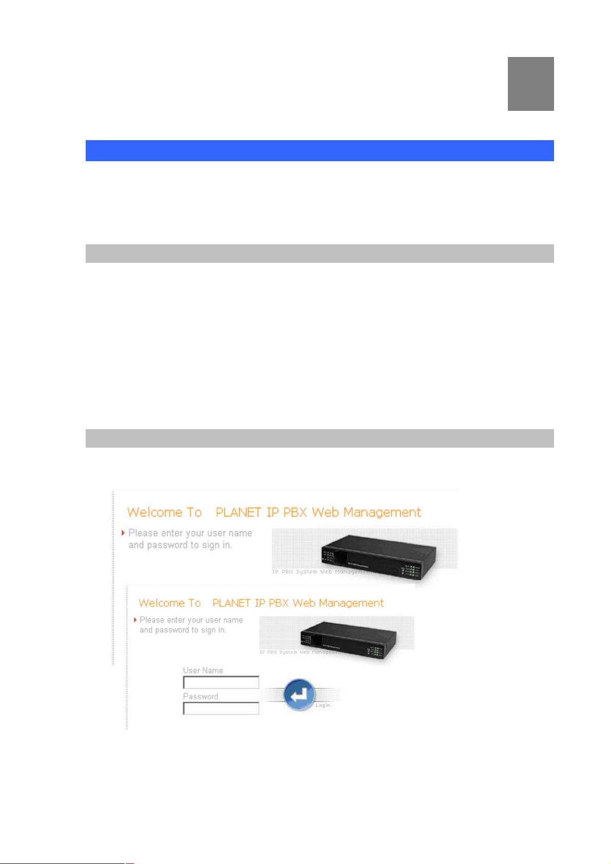
After TCP/IP configurations on your PC, you may now open your web browser, and input
http://192.168.0.1 to logon IPX-1000 web configuration page.
IPX-1000 will prompt for logon username/password: admin / 123
IPX-1000 logon page
(Log on IPX-1000 via username/password: admin /123)
Page 25
21
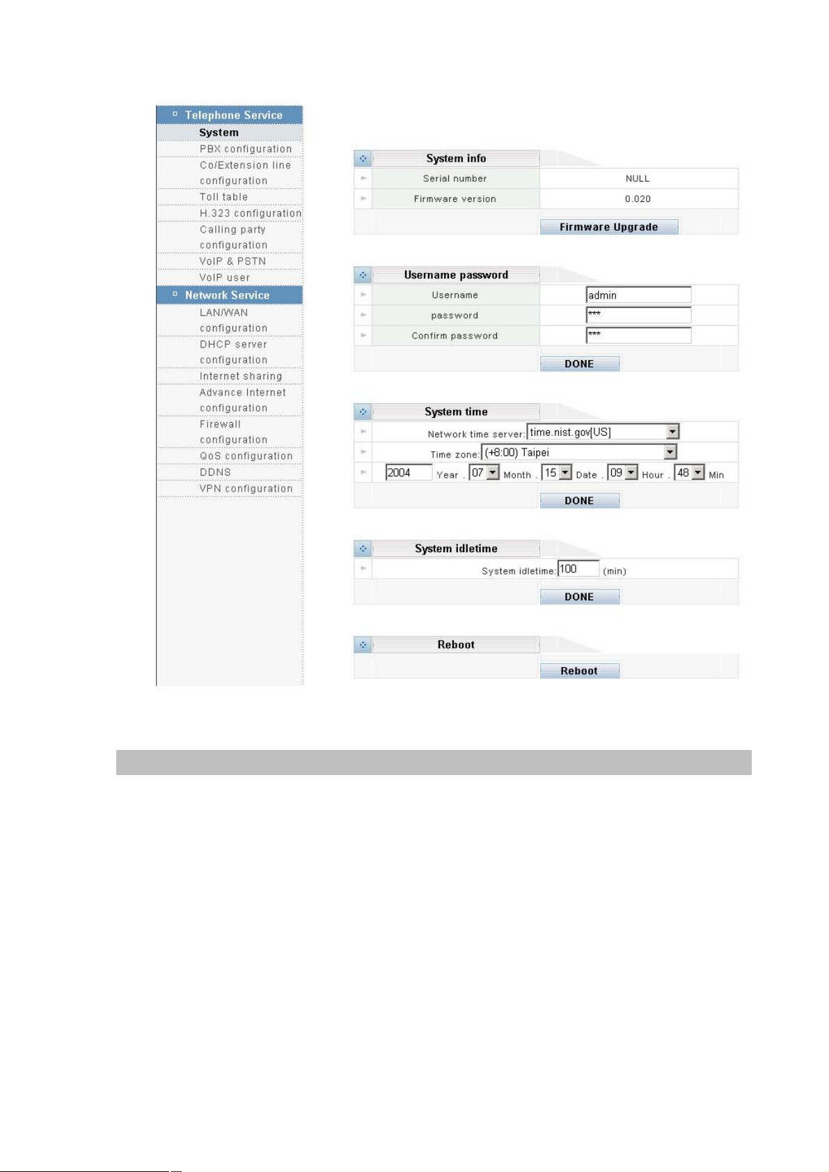
IPX-1000 main page
LAN/WAN Configuration
Please select “LAN/WAN Configuration” on the Network Service configuration menu. After entering
“LAN/WAN Configuration” page. and please clicking LAN configuraion button, the configuration
screen is shown below.
Page 26
22
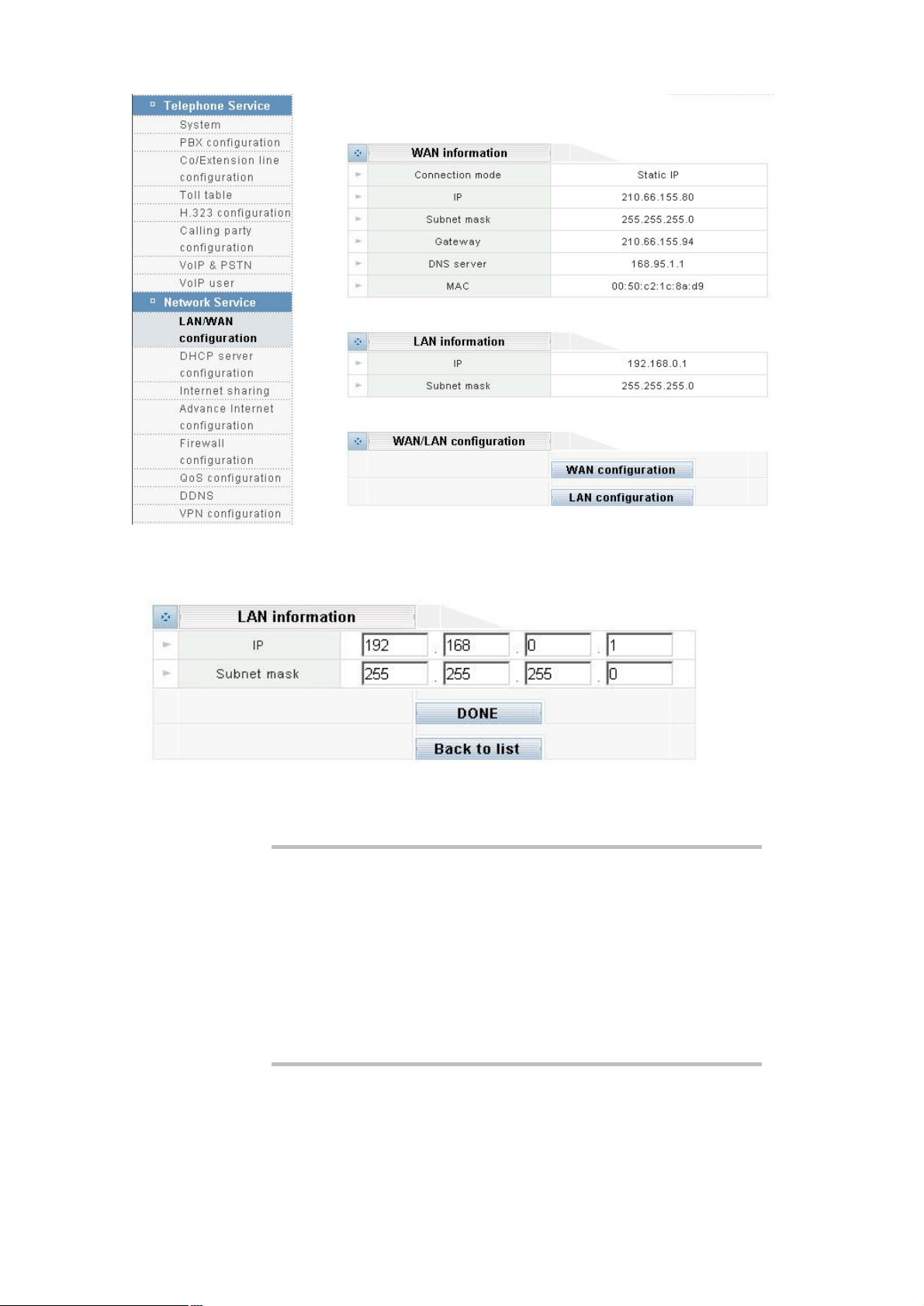
LAN information
Please clicking LAN configuraion button, the configuration screen is shown below.
The LAN infornation Parameter Description of IPX-1000
IP LAN IP address of IPX-1000
Default: 192.168.0.1
Subnet mask LAN mask of IPX-1000
Default: 255.255.255.0
WAN information
Please clicking WAN configuraion button, the configuration screen is shown below.
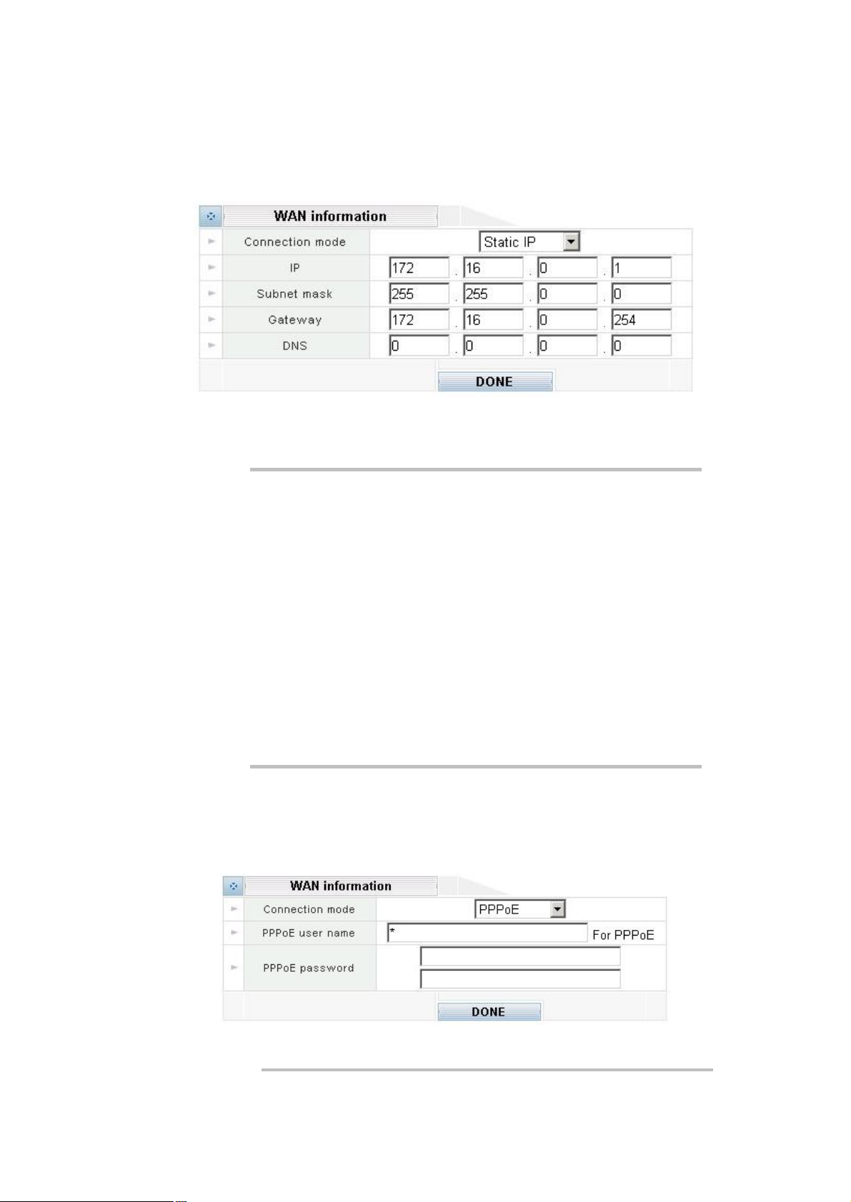
WAN connection type in IPX-1000
The Internet connection type supported in IPX-1000 are PPPoE, DHCP client and the fixed IP
Page 27
23
allocation. Please be sure to choose proper connection type for Internet access.
Fixed IP alloaction
Certain ISP provides a fixed IP address to each of its subscriber. This parameter allows users to setup
the fixed IP address assigned by ISP. Your ISP should provide all the information requied for Internet
access.
The WAN information Parameter Description of IPX-1000
IP WAN IP address of IPX-1000
Default: 172.16.0.1
Subnet mask WAN mask of IPX-1000
Default: 255.255.0.0
Gateway WAN Gateway of IPX-1000
Default: 172.16.0.254
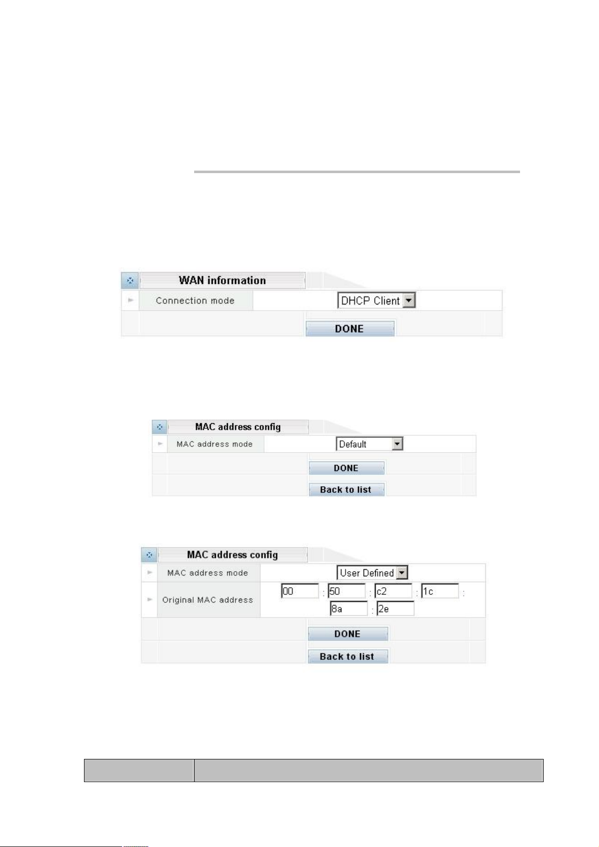
PPPoE connection
If theISP demands PPPoE connection for Internet access, please select PPPoE as connection type,
and insert the username/password by your ISP to connect you to the Internet.
The PPPoE configuration Parameter Description of IPX-1000
Username User name for PPPoE connection
Page 28
24
Default: null
Password Password for PPPoE connection
Default: null
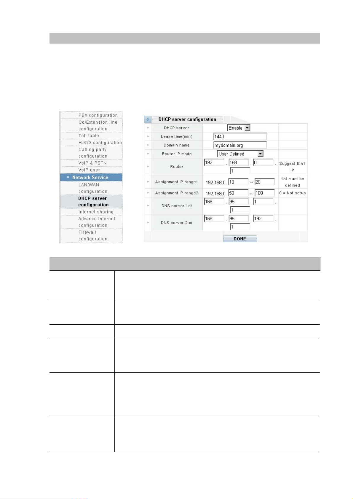
DHCP connection
Please choose the DHCP client connection if ISP automatically assigns IP address for Internet
connecton. Some ISP may require additional information such as Host Name, Domain Name and MAC
address.
MAC Address config
In most cases the MAC address does not need to be set manually. However, it may be necessary for
some cable modem users to set the MAC address manually. In that case, simply enter the new MAC
address and clicking on the DONE button.
Please select User Defined mode of the MAC address mode:
In most cases the MAC address does not need to be set manually. However, it may be necessary for
some cable modem users to set the MAC address manually. In that case, simply enter the new MAC
address and clicking on the DONE button.
Connection Type Date required
Page 29

25
Static IP IP, Subnet mask, Gateway, IP address of DNSserver
/IP
PPPoE Username, Password
DHCP client
i Hint
Usually, noon. But some SIP may require a particular Host name,
Domain name, or MAC (physical) address.
Please consult your ISP personnel to obtain proper PPPoE
address related information, and input carefully.
If Internet connection cannot be established, please
double-check the parameters configured in IPX-1000 or
contact the ISP service staff for support information.
Page 30
26
DHCP Server Configuration
1000’s LAN
ange
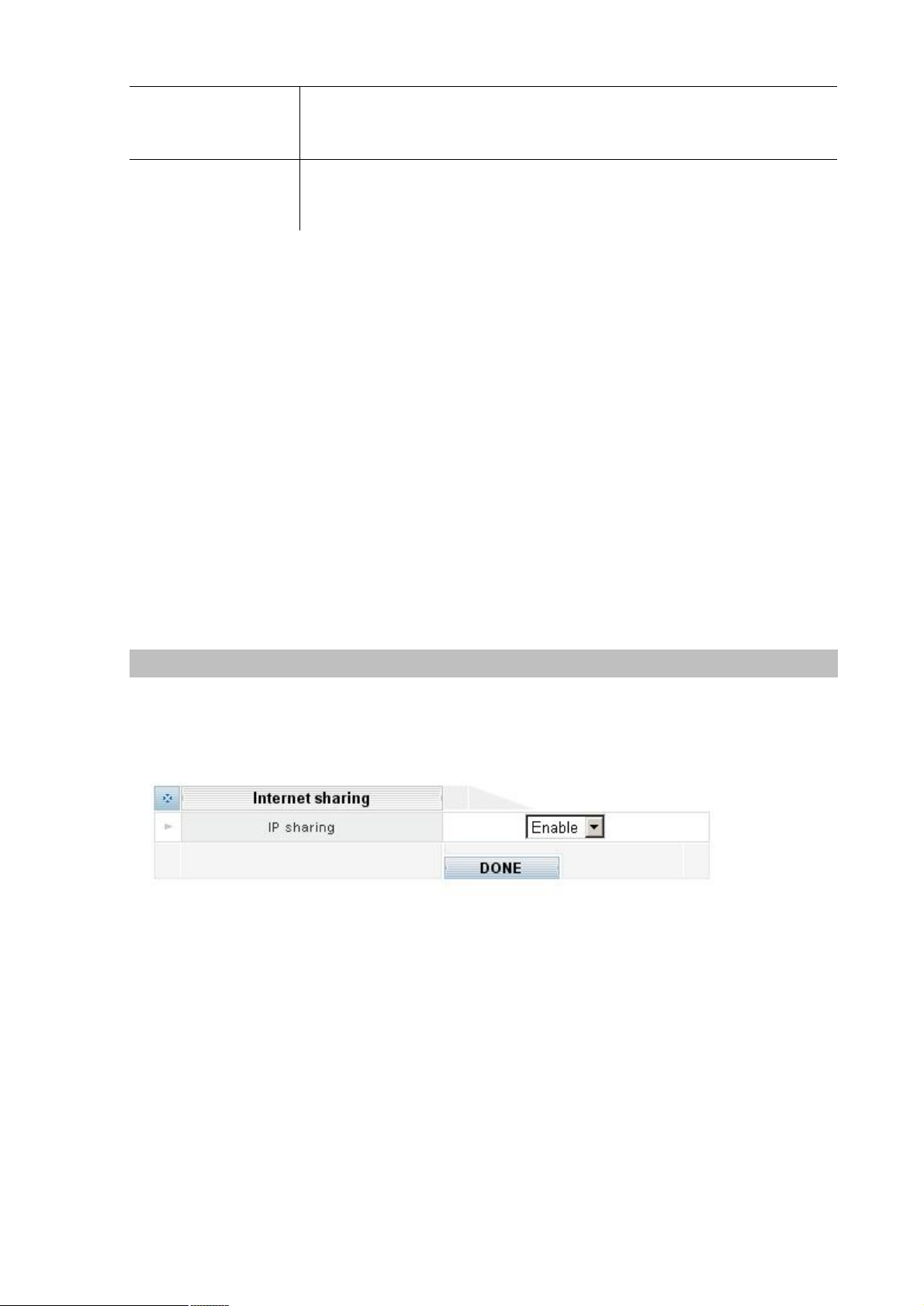
IPX-1000 has a built-in DHCP server that can automatically assign dynamic IP addresses to client PCs
connected to its LAN ports, simplifying the task of IP address management. You can set up two IP
address ranges for the DHCP server to use – the second range will be used only after the first range is
all used up. Being able to set up two IP address ranges makes the system more flexible in terms of IP
address usage.
Please select the DHCP server configuration icon:
Parameter Description
Enabele / Disable
DHCP server
Lease Time (min)
Domain Name Please insert the domain name of the IPX-1000.
Router IP
Assignment IP range
1
Please make sure all the following parameters are set properly before
enabling the DHCP server.
1440 (default value)
The lease time is measured in minutes.
Please insert the router’s IP address of the IPX-1000.
If you want to use IPX-1000’s internal router, please insert the IPXIP address here, or use another router on the LAN then insert its IP address
here instead.
Please insert the first IP address range. The values must be within 1 ~ 254,
and the end value must be greater than the start value.
Note that the first three numbers (unchangeable) should be the same as the
first three numbers of IPX-1000’s LAN IP address. If not, then you must
correct IPX-1000’s LAN IP address setting first.
Assignnment IP r
2
Please insert the second IP address range. The DHCP server will start to use
the second range only after the first range is all used up. If you don’t need to
use the second range, please instert zero for both the start value and the end
value.
Page 31
27
Please insert the first (or the only) DNS server’s IP address. If this IP address
the second DNS server’s IP address. This IP address is optional.
DNS server 1st
DNS Server 2st
is set incorrectly, your PC will not be able to access web sites via domain
names.
Please insert
If you don’t need to uset the 2nd DNS server, please insert zero for the 2nd
DNS server.
DONE
Clicking ing on the DONE button to apply the changes. After clicking ing on the DONE button, the
system refuses to save the changes (reverting back to the old settings), then you need to request a
new IP address for your PC from the DHCP server.
To request a new IP address from the DHCP server, follow these steps:
1. Open the Command Prompt window (sometimes called DOS window) from Windows.
2. If you are using Windows 95/98, enter “ipconfig /release_all”. After the command is completed,
enter “ipconfig /renew_all”.
3. If you are using Windows 2000/XP, enter “ipconfig /release”. After the command is completed,
enter “ipconfig /renew”.
4. If you want to know your PC’s new IP address, enter “ipconfig”.
Internet Sharing
This page allows you to enable the Private IP address and no need to apply from your MIS, but you
must responsible that the routing information out gone to the other network. The benefit of the Private
IP address is can be shared with different party for saving IP number.
Page 32
28
Advanced Internet Configuration
Advanced Internet configuraton - also called IP masquerade, is a process of translating the source
header of IP packets so they will be routable across wide area networks
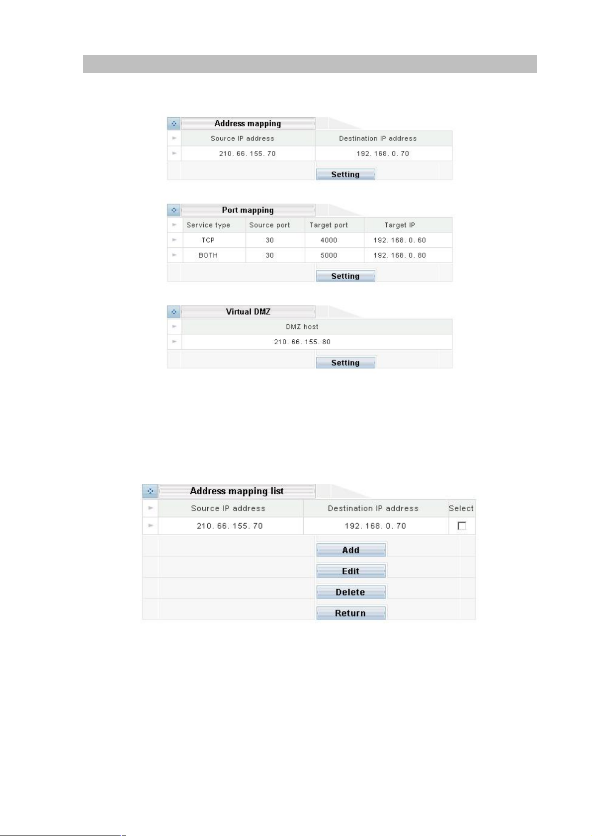
Address mapping
This feature allows public IP address to be associated with one computer on your LAN. All outgoing
traffic from that PC will be associated with that public IP address. Any traffic sent to that IP address will
be forwarded to the specified PC uses the private IP you set here.
Please click Setting button to enter into Address mapping configuration:
Add:Clicking Add botton to step up the machine the packet want to be transferred.
Source IP address: Please fill the pulbic IP address which packet want to be transferred.
Destination IP address: Please fill the target private IP address which packet be transferred
to.
Edit:Please select the IP transparented, clicking Edit to modify the public and private IP Address.
Remember to save after changing.
Delete:Please select the IP transparented,clicking delete to remove the IP you don’t want to
transparent.
Return:Go back to the last page
Page 33
29
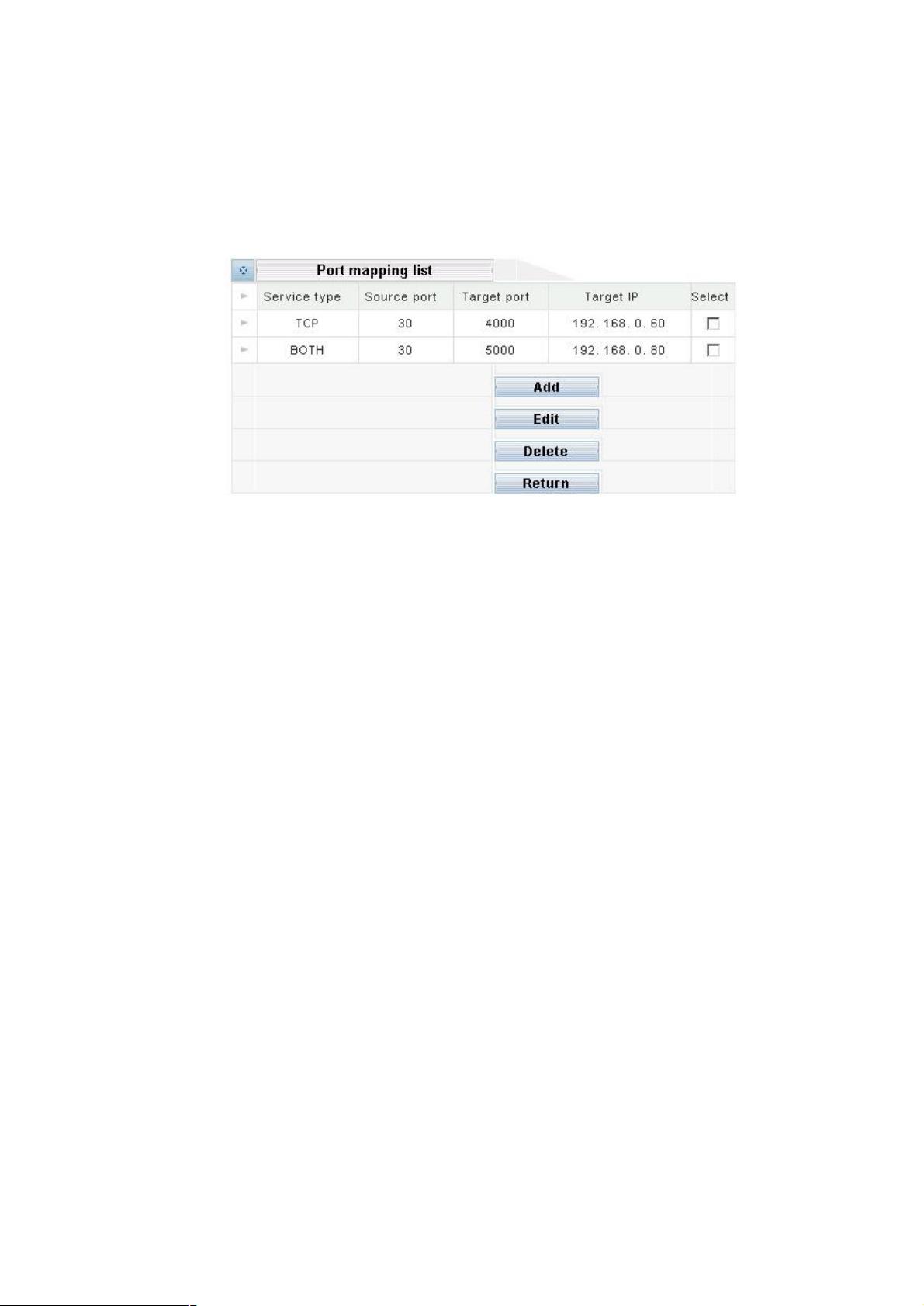
Port mapping
Port mapping (or Port Address Translation - PAT) is the process where packets arriving to a particular
IP address/port can be translated and thus redirected to a different IP/port. This functionality is a way to
create a persistent passage through NAT. Port Mapping is only necessary for incoming connections,
not returning traffic.
Please click Setting button to enter into Port mapping configuration:
Add:Clicking Add botton to step up the machine the packet want to be transferred.
Service type: Please make sure the protocol type service use.
TCP(Transmission Control Protocol),UDP(User Datagram Protocol) or BOTH
Source port: Please fill the port service using
Target port: Please fill the port service will be transferred to
Target IP: Please fill the IP Address of the responsible machine
Edit:Please select the service port transparented,clicking Edit to modify the port and IP Address.
Remember to save after changing.
Delete:Please select the service transparented,clicking delete to remove the service you don’t want
to transparent.
Return:Go back to the last page
Virtual DMZ
In certain situations, you may want to set up a virtual DMZ on one of the computers on your network.
When you establish a virtual DMZ, you open all inbound ports and direct the base station to forward
certain inbound data packets (those that are not in response to a transmission initiated by a local
networked computer and not handled through application-triggered or persistent port forwarding) to a
particular computer on your local network. This computer becomes the DMZ host.
A virtual DMZ, however, should be used only in very specific situations. The computer that hosts the
virtual DMZ is fully exposed to the Internet, and is thus susceptible to malicious attacks and
unauthorized access. If a hacker were to upload a virus to the virtual DMZ, the virus could spread to all
the computers on your network.
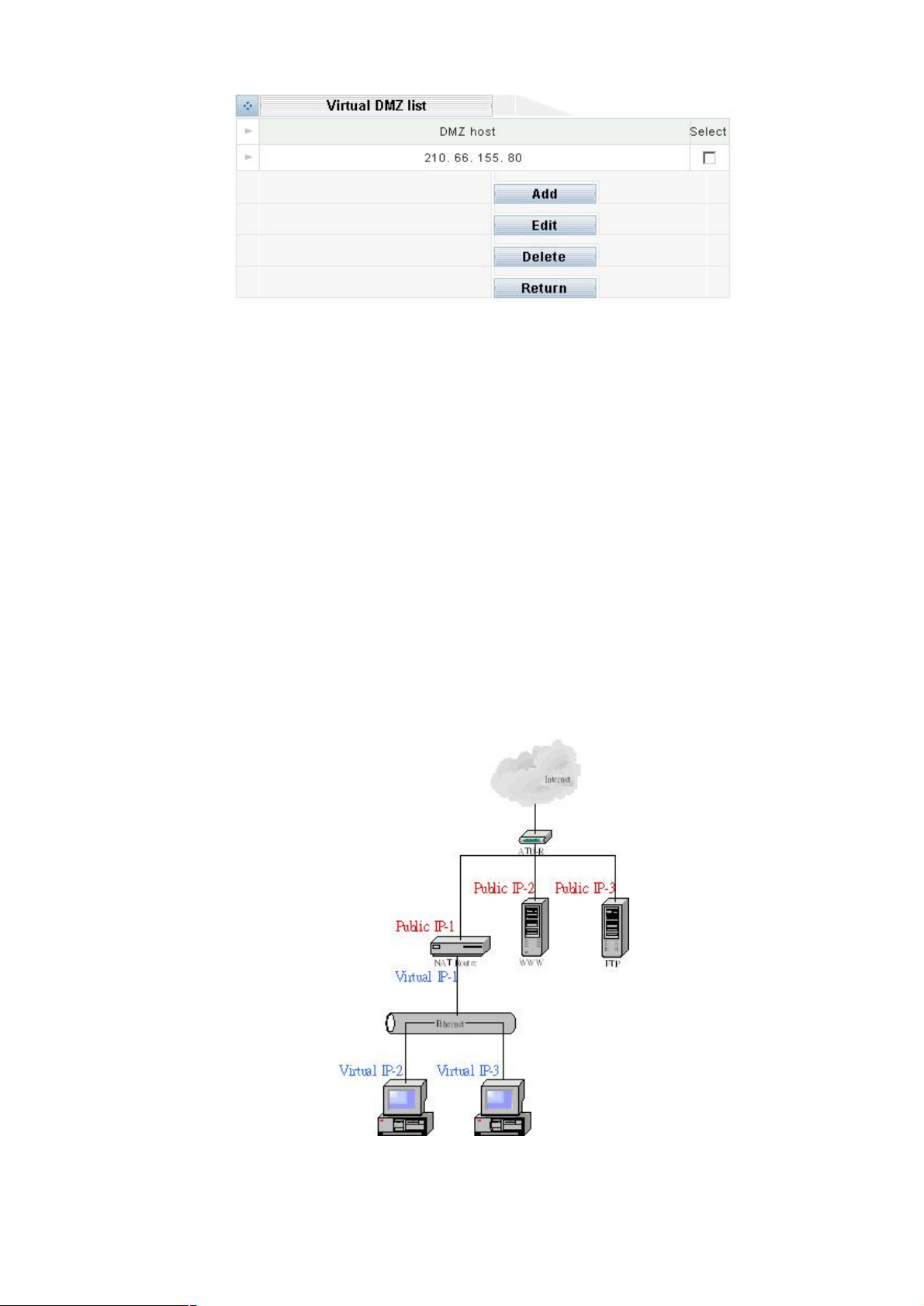
Please click Setting button to enter into Virtual DMZ configuration:
Page 34
30
Add:Clicking Add botton to step up the machine you want to transparent. The configuration will show
the place to let you fill the IP Address.
Note: The ping command can’t be used to call the machine set to transparent mode.
Edit:select the IP transparented,clicking Edit to modify the IP Adderss. Remember to save after
changing.
Delete:select the IP transparented , clicking delete to remove the machine you don’t want to
transparent.
Return:Go back to the last page.
Address Mapping vs. Virtual DMZ
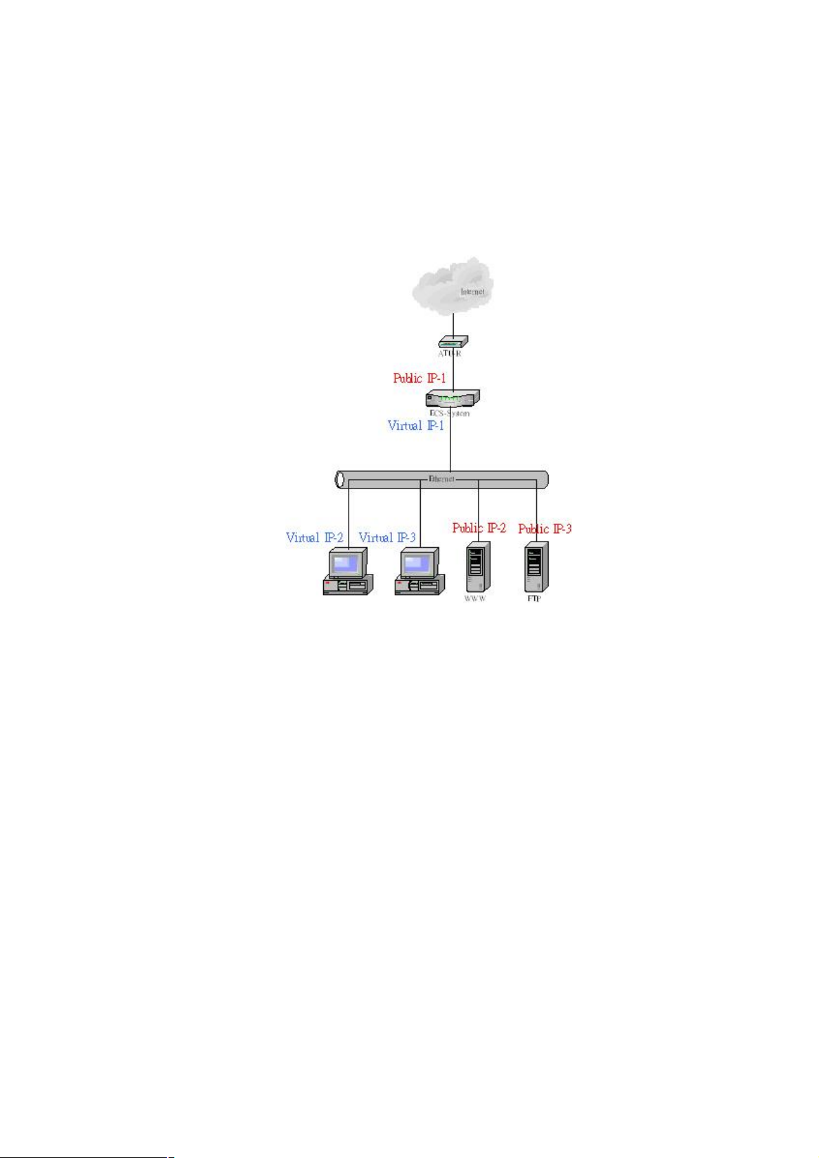
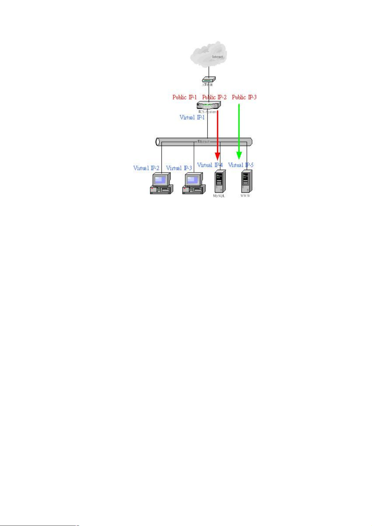
The standard framework of the Intranet
The figure below is the simplest way to construct the intranet. User can access the single server used
public IP address provided by enterprise
The IPX Virtual DMZ framework
Page 35
31
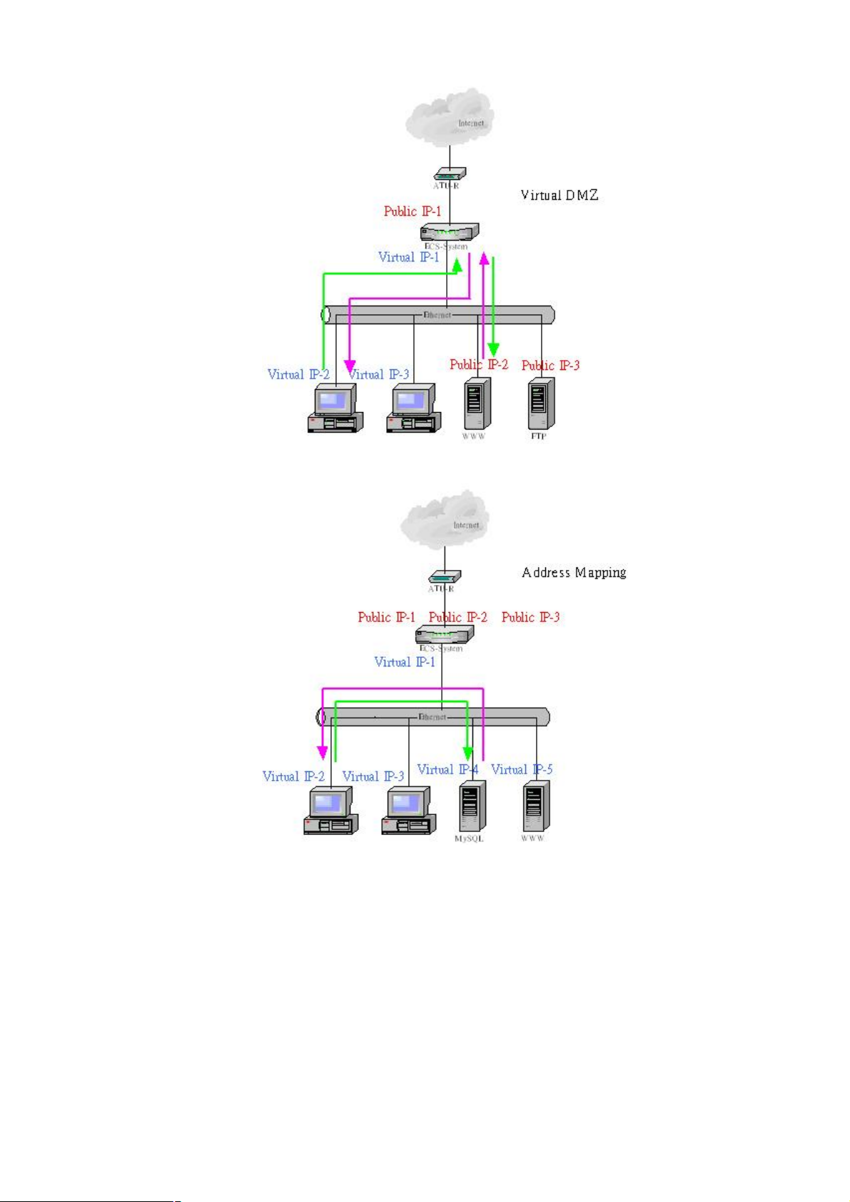
Can change the intranet framework by using Virtual DMZ; can make use of Virtual DMZ to replace the
standard intranet structure without changing the any setting, including the setting of Public IP-2 and
IP-3, and user still can access the server formerly.
To cantrast the standard and Virtual DMZ framework, because all traffic through server Public IP2 and
Public IP3 will be control by IPX-1000, The IPX-1000 have more authority to provide bandwidth for
VoIP
Another important point is the protecting by Firewall. All accessing can be defended and filtered by
IPX-1000. But one thing have to be pay attention, the factory setting about allows all service to pass
through Firewall. So you need to configure your Firewall before contruct the Virtual DMZ framework.
The IPX Address Mapping framework
IPX system’s address mapping framework is designed for the service like Oracle, Internet’s user can
access MySQL existing in intranet.
The point is user accessing the service through virtual IP normally. If you permit user accessing from
Internet, you have to step up a public IP mapping to a private IP. Besides the address mapping, you
can do the work using Port mapping. The matter is the protocol of some service using random port.
The advantage of traffic control provides by Virtual DMZ also by Address Mapping, but you need pay
attention to the configuration of firewall.
Page 36
32
The Contrast of Virtual DMZ and Address Mapping
Decision about using Virtual DMZ and Address Mapping is decided by private or public IP which server
uses. If server is public IP, it is better to establish Virtual DMZ framework. If server is private IP and
permit accessing for Internet, address mapping or port mapping is ideal solution. The purpose is not to
change the infrastructure and setting formally.
We suggest that it is better to use Port Mapping or Address Mapping when server needs to provide
accessing for Internet. The reason is the Virtual DMZ framework will occupy more bandwidth and cause
the System loading bigger. See the figure, all traffic will through IPX-1000 when PC in intranet want to
access server, but Address Mapping won’t.
Merely, no matter Internet or intranet accesses server using public IP in Virtual DMZ framework but
Address Mapping is more complicate. Internet needs public IP to access Server when intranet needs
private IP.
Both of them are the method to provide service for user, just according to the convenient you
considerate!
Page 37
33
Page 38
34
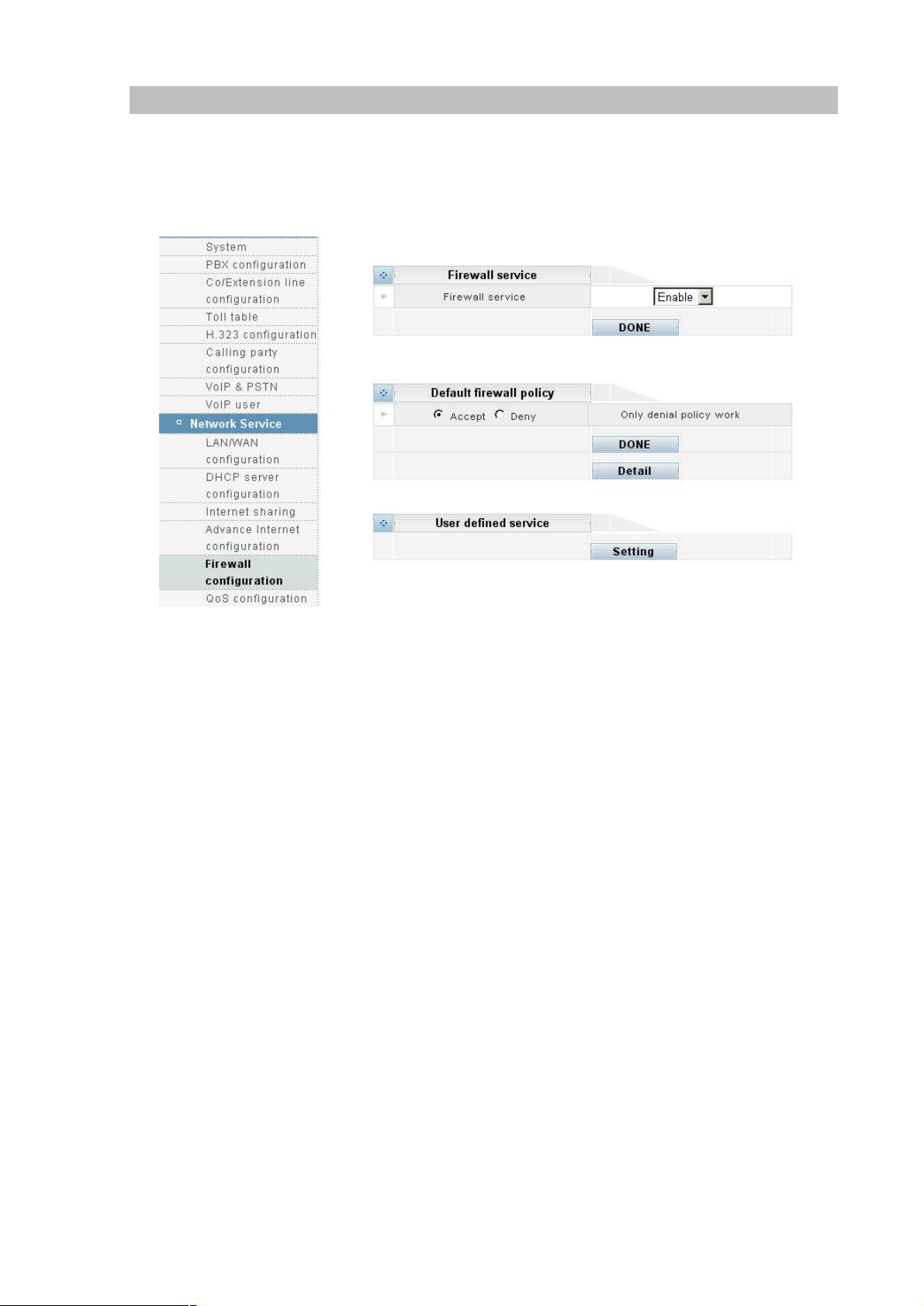
Firewall Configuration
A firewall is designed to prevent unauthorized access to and/or from a private network. It can stop
inappropriate communications into and out of the LAN, preventing hacker attacks. IPX-1000’s built-in
firewall provides hardware based network security via the following two mechanisms. Pleaae select the
Firewall configuration icon:
Firewall service
”Enable”: Enable the Firewall service; ”Disable”: Disable the Firewall service.
Please make sure all the following parameters are set properly before enabling the firewall.
Default firewall policy
Firewall provides Accept mode and Deny mode. The difference between the Accept and Deny mode is
the rule or service you set in detail will be denied to access under the Accept mode but will be permit to
under the Deny mode. On the countary, the rule or service you don’t set in detail will be permit to
access under the Accept mode but denied under Deny mode.
User defind service
You can define the private rule or service yourself by setting user defind service. The rule you defined
will list on the web. The rule will be added to the service of Firewall policy automatically.
Service Name:give a name to the service and it will be list in the firewall policy.
Service Type:the transit protocol service uses
Service Port:the port service uses
Page 39
35
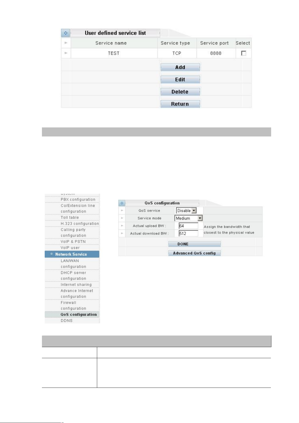
QoS Configuration
QoS (Quality of Service) regulates the bandwidth used by each network services. QoS can prevent this
from happening and make more efficient use of the available bandwidth. QoS is also needed for certain
network services (such as IP phone) where it is essential to guarantee a minimum level of bandwidth in
order for the service to be usable.
Note: All bandwidth (BW) numbers shown above are in units of kbit/second.
Please select the QoS configuration icon:
Parameter Description
QoS service Enable or Disable QoS.Service
Voice Good: voice communication has higher priority
Service mode
Medium: no priority between voice and data
Data Good: data communication has higher priority
Page 40
36
From the drop down list, select the actual upload bandwidth
(upload speed). In
ë
Actual upload BW
Actual download BW
some cases the actual bandwidth may be smaller than what your ISP claims.
Select the closest value based on your real life experience instead of what
your ISP claims.
From the drop down list, select the actual download bandwidth (download
speed). In some cases this bandwidth may be smaller than what your ISP
claims. Select the closest value based on your real life experience instead of
what your ISP claims.
DONE
Clicking on the DONE button to apply the changes.
Note
l The unit for QoS configuration is kbit/sec
l Actual BW > Maximum BW > Guaranteed BW
l Actual BW > Upload and Download Guaranteed BW
Advanced QoS config
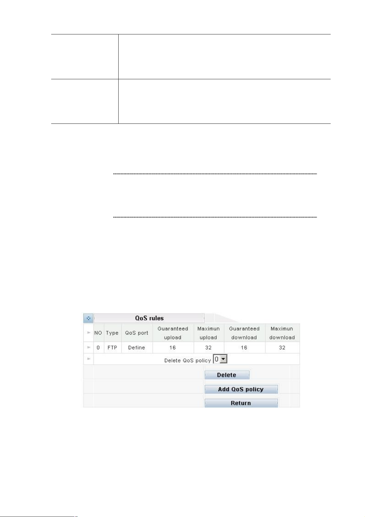
IPX-1000 provides two standard rules: one for H323 (IP phone) and the other for FTP. Usually you
want to guarantee a minimum bandwidth for H323 in order to have an acceptable IP phone quality. And
you may want to limit the bandwidth for FTP so the network will not perform poorly when someone is
uploading or downloading a large file. Note that if “-1” is entered into any BW (bandwidth) field, it means
that no QoS is applied to that particular bandwidth. For example, if all four BW fields are entered “-1” for
FTP, it means that FTP is not regulated by QoS at all (this is generally not a good idea).
Delete:
To delete a user rule, simply select its number from the drop down list and clicking on the
DELETE button.
Add QoS policy:
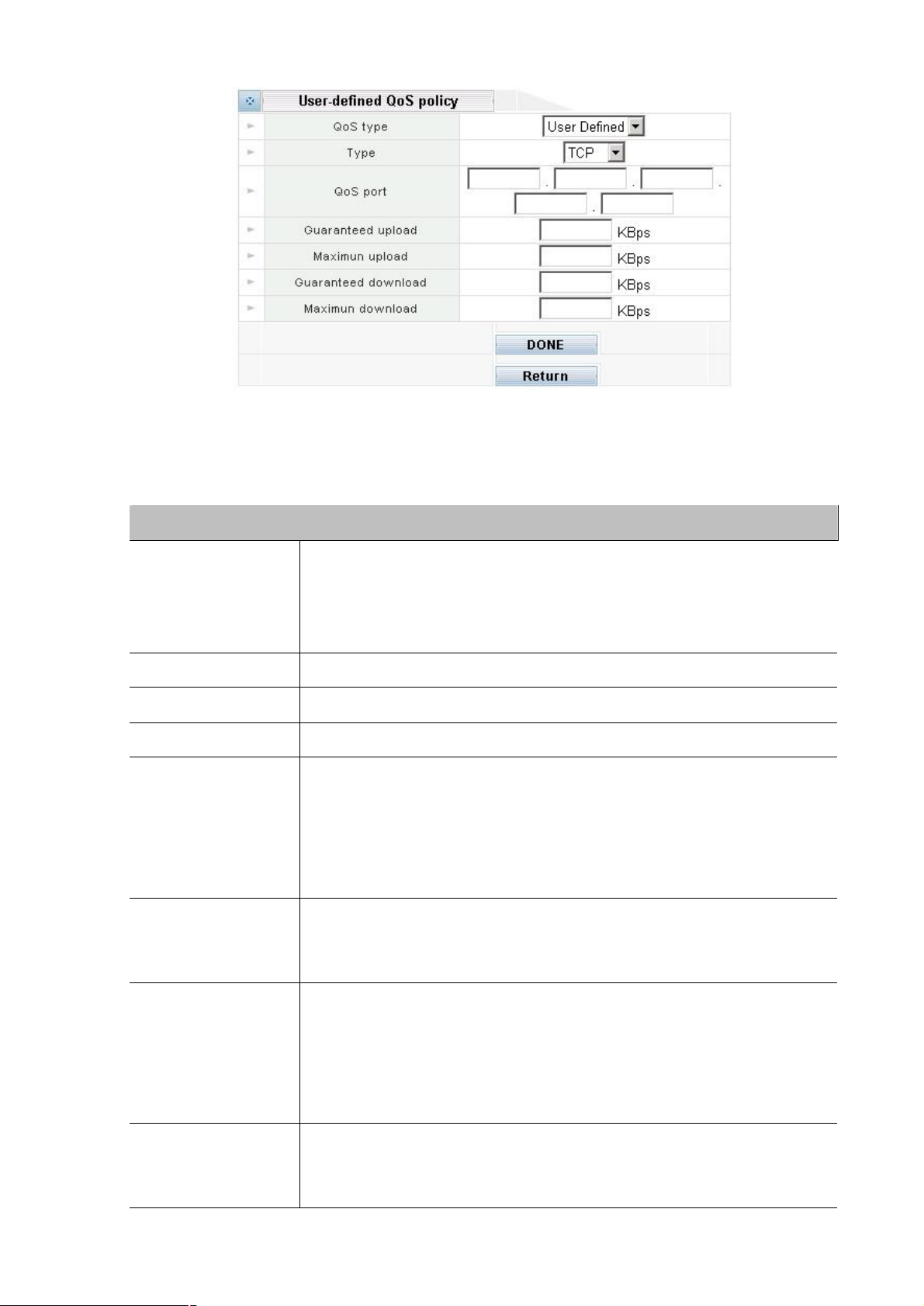
Please clicking Add QoS policy button to add a User-defined QoS policy:
Page 41
37
DONE
1” is entered into any BW
QoS is applied to that particular bandwidth.
it means
the service is guaranteed to have this
available to it no matter how busy the network is. Note that
e the
performance of others since a portion of the upload bandwidth is set aside and
the service will not be allowed to use more than
able. Note that this bandwidth
the service is guaranteed to have this
available to it no matter how busy the network is. Note that
service may degrade the
performance of others since a portion of the download bandwidth is set aside
the service will not be allowed to use more
bandwidth even if more bandwidth is available. Note that this
Clicking on the DONE button to apply the changes.
Return
Go back to the last page.
Parameter Description
Up to ten user rules can be defined. Note that if “-
QoS rules
No
Type
Qos Port
Guaranteed upload
Maximum upload
(bandwidth) field, it means that no
For example, if all four BW fields are entered “-1” for a certain rule,
this rule is not regulated by QoS at all and you might as well delete it.
The rule number automatically assigned to the rule by the system.
TCP, UDP or BOTH (TCP plus UDP).
Up to 5 ports can be defined in each rule.
Guaranteed upload bandwidth –
bandwidth
guaranteeing an upload bandwidth for a service may degrad
not available to other services.
Maximum upload bandwidth –
this bandwidth even if more bandwidth is avail
cannot be larger than the Actual Upload BW.
Guaranteed download bandwidth –
bandwidth
Guaranteed download
Maximum download
guaranteeing an download bandwidth for a
and not available to other services.
Maximum download bandwidth –
than this
bandwidth cannot be larger than the Actual Download BW.
Page 42
38
DDNS
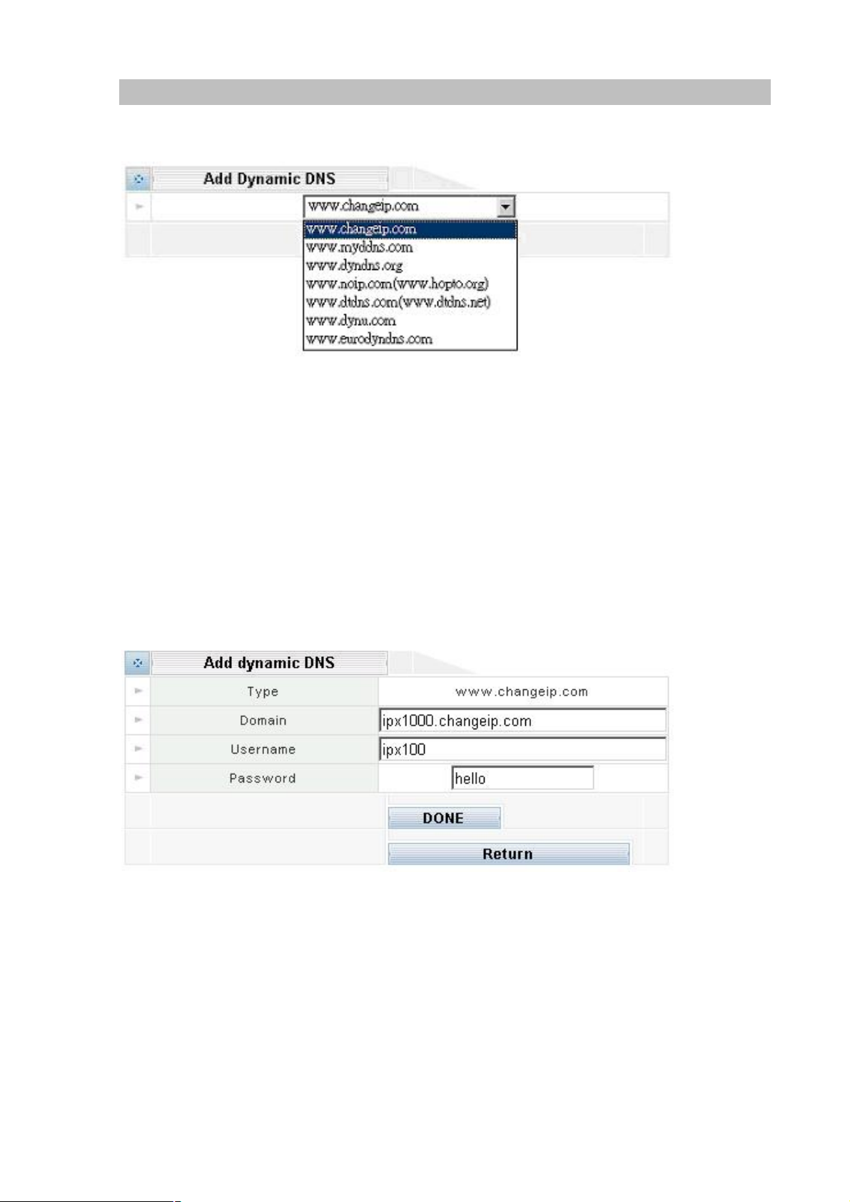
This device supports many popular Dynamic DNS service providers. Select the company that you want
to join then clicks Add button. There are seven DDNS service provides of your choices.
Note1: This Device only allows register to one DDNS service provider.
Note2: Before using this DDNS service, you should apply an account first.
Note3: This device can support DDNS service provider have various choice of
user define names by selecting the appropriate company.
Selecting one DDNS service provider. For example, www.changeip.com
After get an account from DDNS service provider.
You should have the following information.
Domain: DDNS domain name.
Username: User login name for DDNS service.
Password: User password for DDNS Service.
Please clicking DONE button, you will see the configuration screen below:
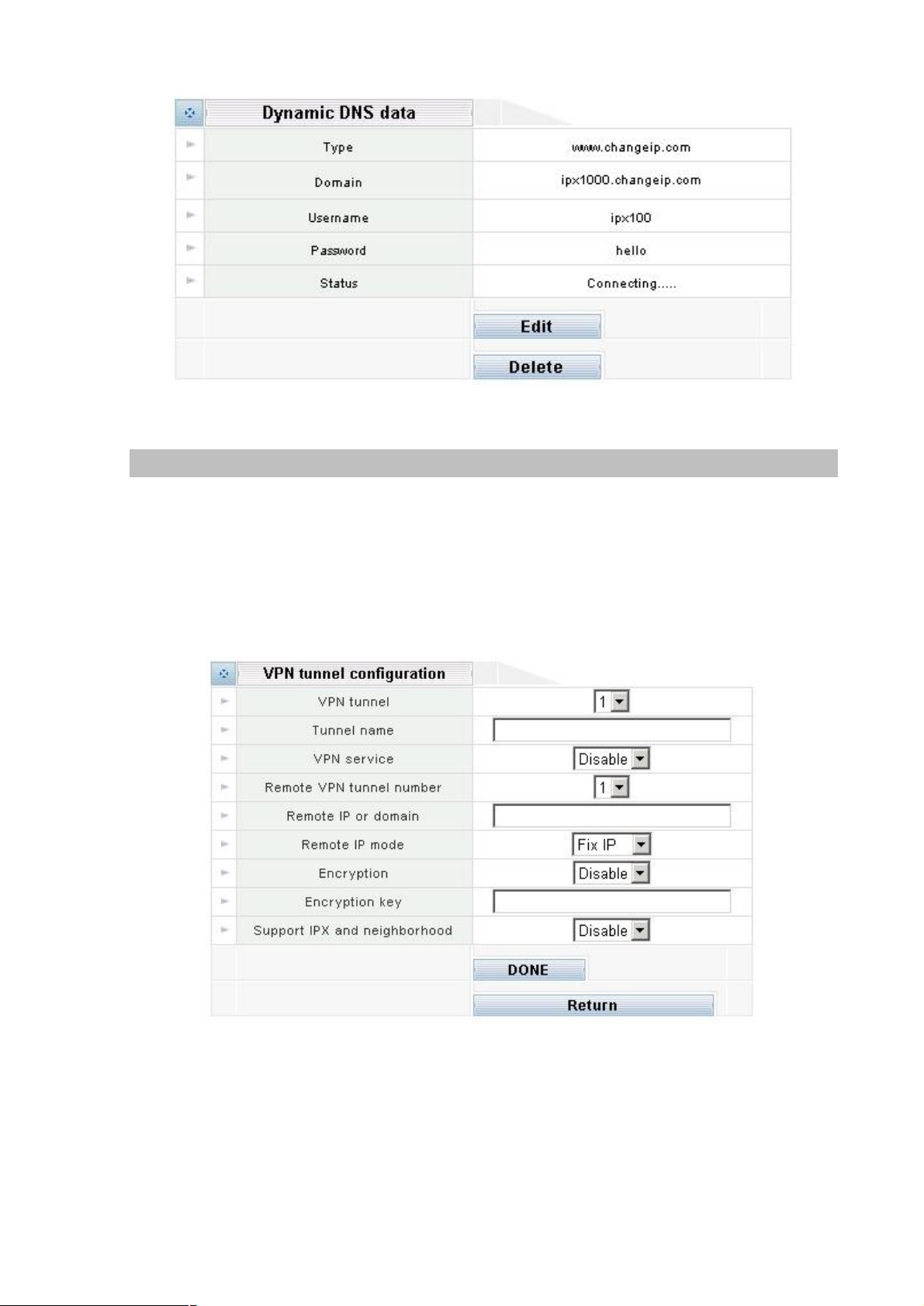
The screen could choice Edit or Delete the DDNS account.
Type: The DDNS service provider you have selected.
Domain: DDNS domain name.
Username: User login name for DDNS service.
Password: User password for DDNS Service.
Stauts: Connecting à Trying to connect DDNS server.
Connected à Successfully connected to DDNS server.
Page 43
39
VPN Configuration
The IPX Series VPN Client creates a Virtual Private Network (VPN) connection between one IPX
machine and the other corporate IPX machine’s network to maintain the confidentiality of private data.
The IPX Series VPN Client provides an easy-to-use solution for secure, encrypted access through the
Internet for remote users. The IPX Series’ user establishes the VPN connections policies for the IPX
Series VPN Clients each other.
Please clicking Add button to enter into VPN tunnel configuration:
Page 44

40
Parameter Description
by the other side to which num of the tunnel can be connected. This option has
the right
IPX Series’ VPN service supports max 4 connections. Tunnel num can be tell
VPN tunnel
relative to “Remote VPN tunnel number”.
Tunnel name Type a human-friendly name for your new connection.
VPN service Decide to Enable or Disable this tunnel.
The tunnel number of the remote site we connected. Verify that the tunnel
Remote VPN tunnel
number
number of the remote site is correct or change as necessary, check with the
remote system’s administrator to make sure that they have given you
tunnel num on the VPN
Remote IP or domain
Remote IP mode
Encryption
Encryption key
Support IPX and
neighborhood
Type in the valid Internet address or domain name of the remote IPX Series
machine you are trying to connect to.
Please open the drop down menu labeled to decide remote IP mode is fix or
float one.
Please open the drop down menu labeled to enable or disable encryption on
the tunnel.
Please fill encrypted key the same as the remote IPX series machine. Note:
passwords are case sensitive!
Please check “NetBIOS over TCP/IP” and “IPX/SPX” if that protocol is both in
use in the local and the destination (VPN) network, then you can open the
drop down menu labeled to decide whether use this function.
IPX VPN provides powerful VPN router feature and user-friendly web setup for SOHO & enterprises.
This IPX VPN provides four features as below.
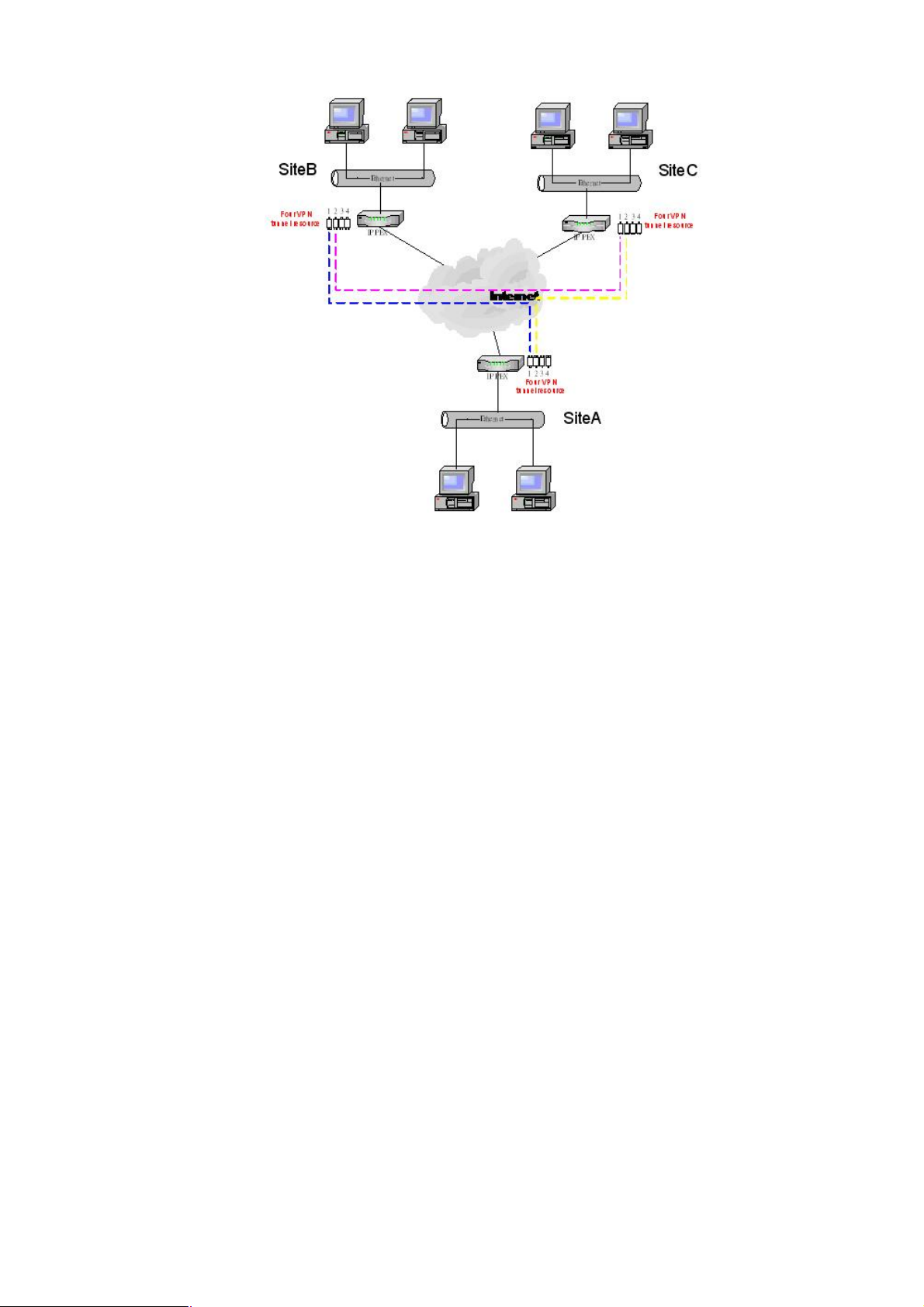
1. It provides up to four sections of peer-to-peer VPN tunnels.
IPX VPN supports 4 channel of VPN resources. In other words, any IPX VPN could connect up to four
IPX VPN units.
Page 45
41
Example:
Site A wants to establish VPN connection to site B & C.
Site B wants to establish VPN connection to site C.
First, site A select tunnel 1 as the channel to site B then site B select tunnel 1 to complete this
connection.
Second, site A select tunnel 2 as the channel to site C then site C select tunnel 2 to complete this
connection.
Third, site B select tunnel 2 as the channel to site C then site C select tunnel 1 to complete this
connection.
2. The packet could be encrypted or non-encrypted.
IPX VPN router supports peer-to-peer packets encryption. It uses 128Bit encryption. User could enable
encryption or disable encryption for each connection.
3. IPX & neighborhood.
IPX VPN provides an easier way to make Windows user to find other computer by name. It supports
Microsoft neighborhood & IPX by enable IPX and Neighborhood.
4. IP address setup
IPX VPN could support both FIX IP & Float IP address
In general, peer-to-peer VPN connection requires two end points have Static IP address. Because of
IPX VPN could support DDNS service and allowing remote site to enter domain name. Therefore, by
select Float IP and DDNS domain as the remote IP address, IPX VPN could find end point both FIX IP
non-Fix IP address.
Please note that to prevent potential collision in the VPN environment. It requires
end_point-to-end_point uses IP address ranges differently.
For example, Site A LAN IP 192.168.0.x. Site B LAN IP 192.168.1.x
Page 46
42
Chapter 4
4
Do not interrupt the upgrading procedure during proceeding; or
Telephone Service Configurations
IPX-1000 Telephony Functions
IPX-1000 comes standard with 2 CO ports and 4 extension ports. Basically any analog telephones can
be used, but it is better to use telephones with a “Flash” key which generates hook flashes within the
range of 100 ~ 700 milliseconds. The Flash key is used in many operations such as transferring a call.
Although you can flash the hook manually without using the Flash key, it will be quite inconvenient and
subject to timing errors.
System
System info
Serial Number: factory S/N#
Firmware Version: software version
Firmware upgrade: software update
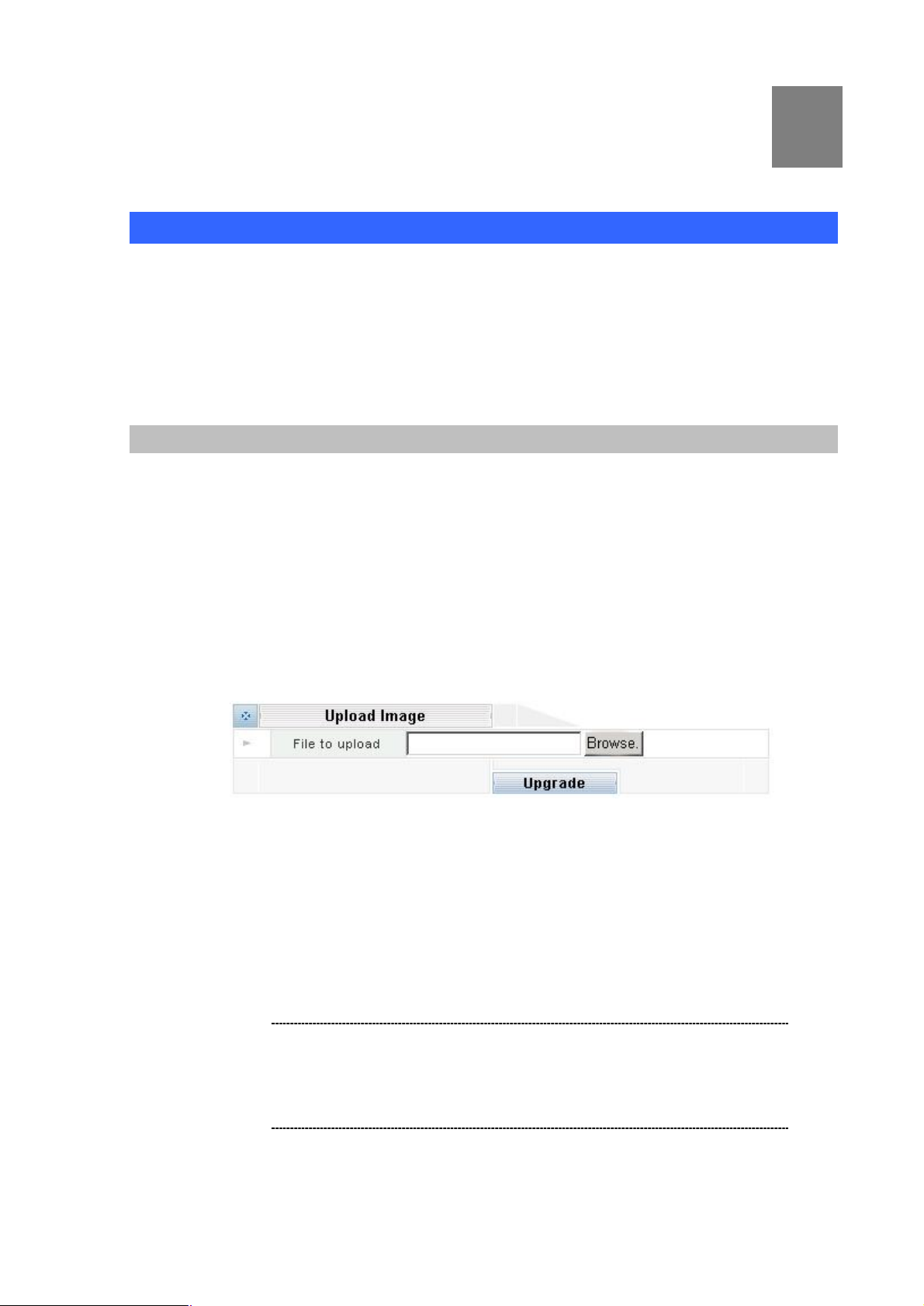
You can upgrade the Firmware by clicking the Upgrade Firmware button. You need to obtain the
firmware upgrade file first.
This screen is displayed when you clicking the Upgrade Firmware button on the Status screen.
This screen allows you upgrade the Firmware (software) in your IPX-1000. Before using this
screen, your must download the upgrade file to your PC.
Please follow this procedure:
Clicking “Upgrade Firmware” button, a dialog box appears. Use “Browse” button to locate the
upgrade file in your computer, then clicking “Start Upgrade” to start the upgrading.
i Hint
l The upgrade may take several minutes.
l When the upgrade is completed, the IPX-1000 will restart. This
will cause any existing connections to be terminated.
l
the inner component might be permanently damaged.
Page 47
43
Username password
Call ID (Caller ID Pass
the check mark
Username: 16 characters (a~z, A~Z, 0~9)
Confirm Password: password confirmed
Password: 16 characters (a~z, A~Z, 0~9)
System time
Network Time Server: time server select
Time Zone: time zone select
System idle time
System idle time: default 20min (1 to 1000min)
Reboot
Reboot: system reboot
PBX Configuration
IPX-1000 comes standard with 2 CO lines and 4 extension lines. Basically any analog telephones can
be used, but it is better to use telephones with a “Flash” key which generates hook flashes within the
range of 100 ~ 700 milliseconds. The Flash key is used in many operations such as transferring a call.
Although you can flash the hook manually without using the Flash key, it will be quite inconvenient and
subject to timing errors.
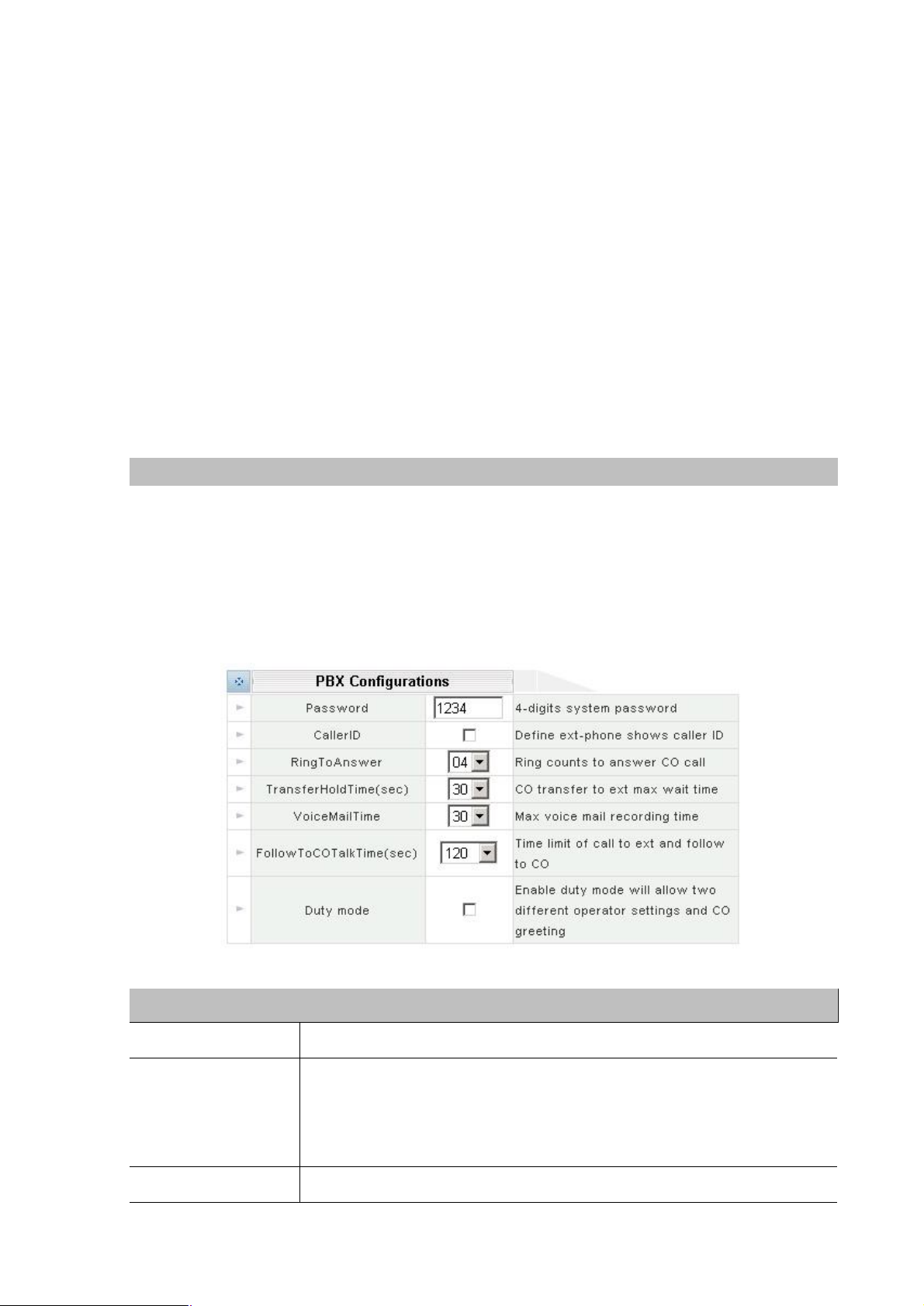
Please select the PBX configuration icon:
Parameter Description
Password This is the password used to login the system.
Please clicking on the box to enable Caller ID Pass Through - a check mark
will appear in the box. If Caller ID Pass Through is enabled, the system will
Through)
Ring To Answer Number of rings the system will wait before answering incoming calls.
pass caller ID information through to the extensions. Otherwise, it will not.
Clicking on the box again to disable Caller ID Pass Through –
will disappear from the box.
Page 48
44
Transfer Hold Time
Transfer
seconds), the system will cancel the transfer and try
a CO
ble the duty mode operation, which allows you
(Transfer Recall Time)
After being transferred to an extension, if a call is not answered within
Recall Time (measured in
to re-transfer the call to either the voicemail box of that extension or the
operator, based on the caller’s choice..
Voicemail Time (Max.
Voicemail Length)
Follow To CO Talk
Time (Max. OPF
Duration)
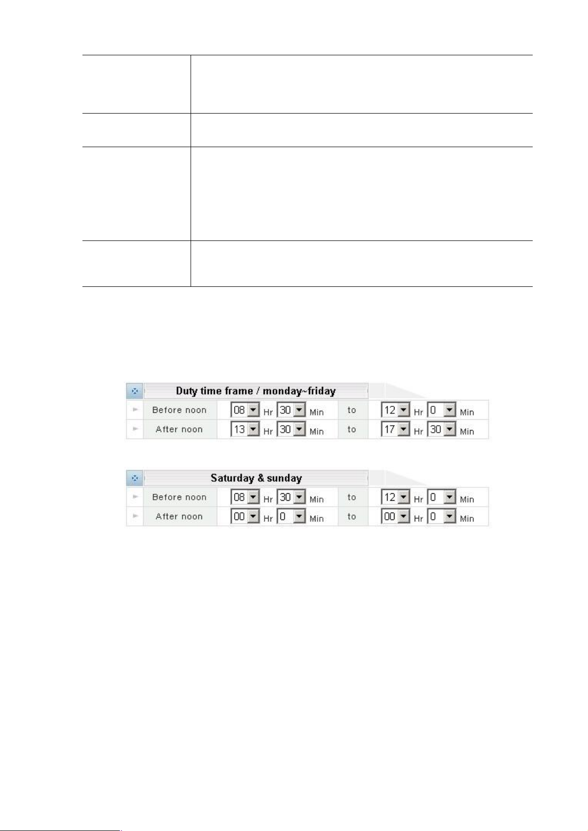
Duty Mode.
Duty Time frame
The system works in the regular mode (On-Duty Mode) during the duty time, and in the Off-Duty Mode
outside the duty time. The day is partitioned into two time sections (Section 1 and Section 2),
accommodating lunch break and such. Weekdays (Monday thru Friday) and weekends (Saturday and
Sunday) are also separated for greater flexibility.
This is the maximum recording time (in seconds) that the caller is allowed to
leave a voicemail message. Maximum setting is 50 seconds.
This is the maximum duration (in seconds) allowed for an OPF (Off-Premises
Forwarding). If an extension has OPF enabled, an incoming call to that
extension will be automatically forwarded to an off-premises location via
line. If the call comes in from a CO line originally, then a total of two CO lines
will be involved in establishing this communication link. This is why you may
want to put a limit on the duration of an OPF so that it does not tie up two CO
lines for an extended period of time.
Pleaese checks this box to ena
to define two duty times: on-duty and offduty. The system can be set up to
work differently in these two duty times.
Page 49
45
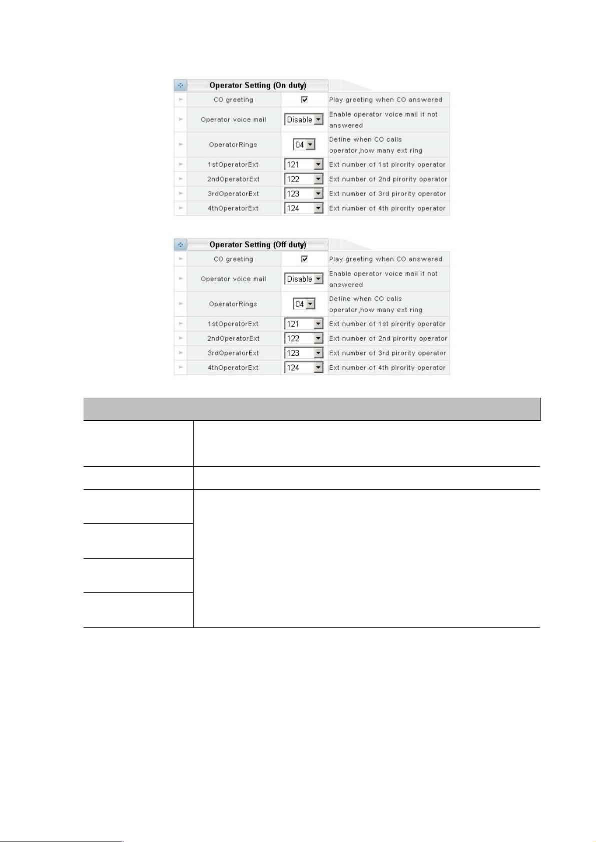
Operator Setting (On duty) / (Off duty)
This is the code that a caller dials to get to the operator. Your choices are “0”
must be different from the CO Access Code
Enter up to four operator extensions here. Operators are prioritized. The first
he first operator
the system
Parameter Description
CO Greeting
Operator Voicemail Enable operator voicemail if the operator fails to answer the call.
1st Operator
Extension
2nd Operator
Extension
3rd Operator
Extension
4th Operator
Extension
Save configurations
Please click on the DONE button to apply the changes.
(recommended) and “9. This code
(see above).
operator has the highest priority, which means he/she will be t
that the system will try to access. If the first operator is busy, then
will try the second operator, and etc.
Advanced PBX config
Advanced PBX configuration is the procedures of configuring the busy tone on Planet IPX -1000.
IPX-1000 in order to release line ports after PSTN caller party is hung up.
A caller makes a telephone call to IPX-1000 from PBX/PSTN side and calls to other VoIP device
through the IPX-1000. If the IP side of other VoIP devices do not answer the call and the caller hang
Page 50
46
up, PBX/PSTN will give IPX-1000 a busy tone automatically. If the other VoIP device of IP side answers
and hangs up the phone, the IPX-1000 will release the line port automatically without analyzing busy
tone from PBX/PSTN.
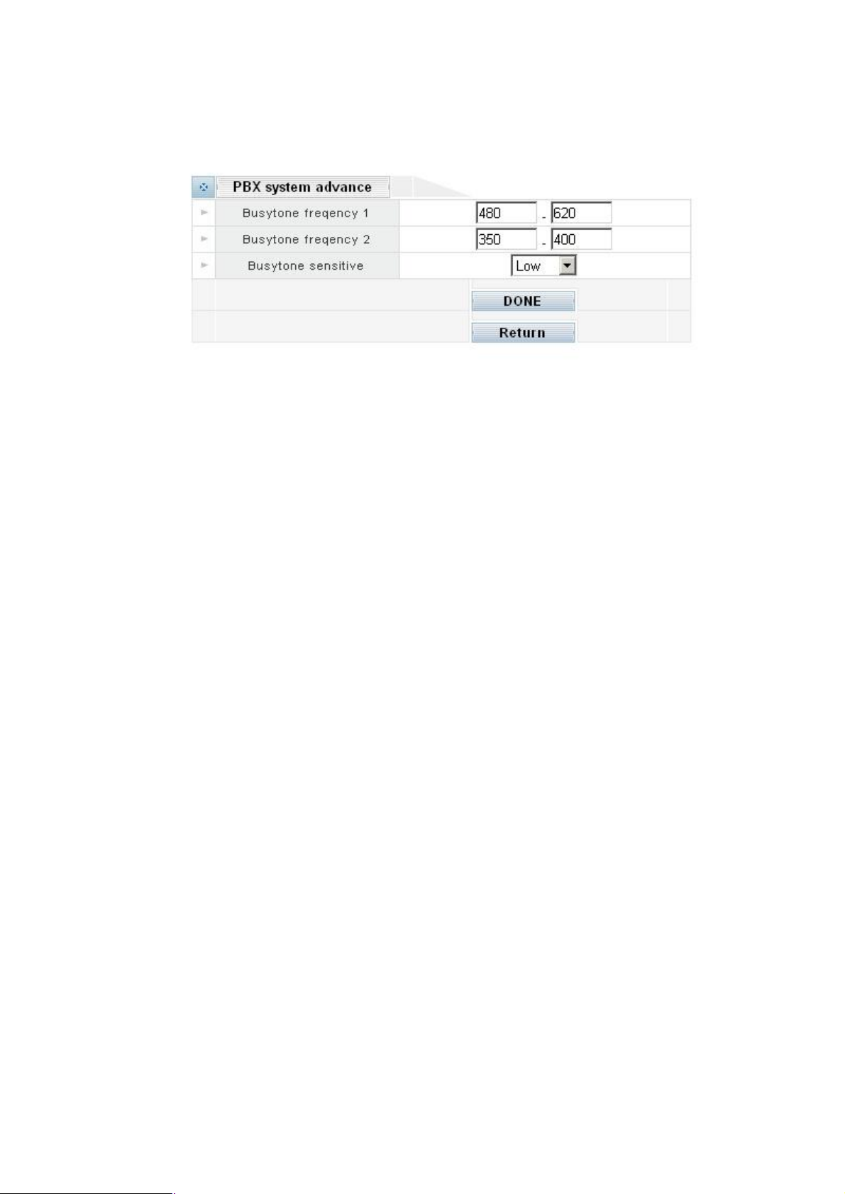
PBX system advance
There are three parameters received from PBX/PSTN.
Busy tone frequency 1
Busy tone frequency 2
Busy tone sensitive: High, Median, Low level
Because the different rule and frequency from other countries, parameters have to be properly
configured to recognize busy tone correctly.
How to configure busytone on IPX-1000
IPX-1000 has a default setting of busytone (busytone frequency 1; busytone frequency 2 and busytone
sensitive), which is based on busytone of the Taiwan Telecom PSTN network. If the busytone was
recognized correctly, the DSP IC in IPX-1000 will release the line port connected to PBX/PSTN
immediately when detecting of busytone. Otherwise it may be released after one minute or lock this line
permanently. The tone table parameters are shown as following example:
Busytone frequency 1:
480/620: Low frequency is 480 HZ, High frequency is 620 HZ
Busytone frequency 2:
400/450: Low frequency is 400 HZ, High frequency is 450 HZ
Most busy tone of PSTN or PBX is composed by two different frequencies, in Taiwan, for example,
480Hz+620Hz. In such case, you have to assign the two frequency values. But in some area, the busy
tone frequency may be composed by only one frequency; in this case, you have to assign the two fields
with same value. For example, if your PSTN busy tone is single frequency, let’s say 450Hz. Then you
have to fill the two fields with 450/450. The IPX-1000 will recognize them as single frequency.
The IPX-1000 allows you to enter two groups of busy tone setting. Because in many cases.
The gateway has to detect two sources of busy tone. One from PSTN side and the other from PBX side.
So it is necessary to have two groups of setting.
If the IPX-1000 can’t hang up the phone, maybe it is because the PBX/PSTN
Frequency is not the value as default shown as above; you need to adjust Tone Table parameters
manually
Page 51
47
Adjust Tone Table parameters manually
If you are sure that the busy tone frequency has been properly set, but the IPX-1000 still cannot release
the line port in three seconds, try to adjust the busy tone sensitivity. The default value is “Median”, the
“High” sensitivity will decrease the qualify condition of busy tone and make it more easy to detect busy
tone. And the “Low” sensitivity will make it more difficult to recognize busy tone. Sometimes, human
speech may cause DSP false recognize as busy tone. If so, lower sensitivity will reduce such problem.
But in any case, if the line port of IPX-1000 was locked, please use “disconnect” in CO & EXT selection
to release the line locked
Co/Extension line Configuration
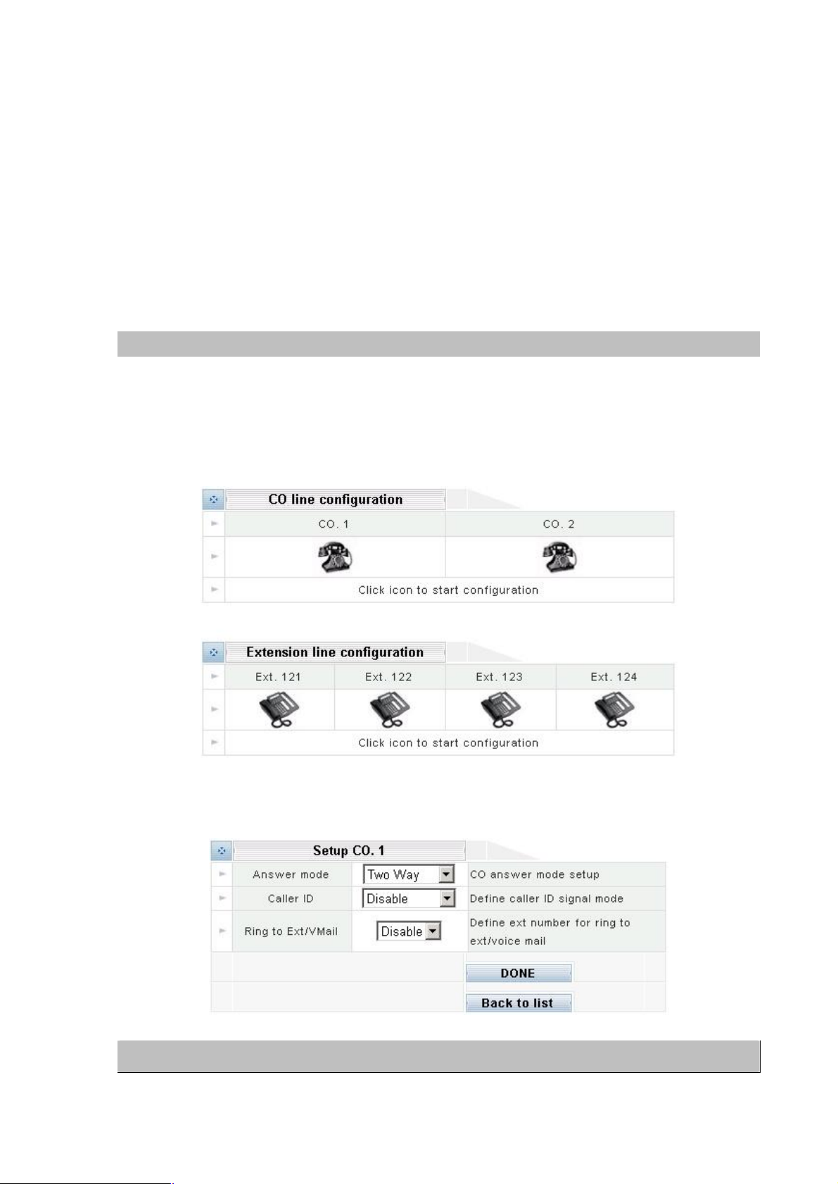
CO & Ext Setup
This menu lists all CO lines and extensions. However, it does not mean that all these lines have
physical connections. For an unconnected or unused CO line, you should enter its setup menu and set
its operation mode to “Disabled”. This way the system knows which CO line(s) should never be
accessed. To set up a CO line or an extension, clicking on its icon.
CO line configuration
Please clicking Co line telephoen icon to enter into Setup CO.x:
Parameter Description
Page 52

48
Answer Mode
Ring Through Extension (see below) directly, bypassing the system’s auto
transferred to the
directly, bypassing the system’s
the following three caller ID types: FSK, DTMF before ring,
your local phone company to find out
please
Specify which extension the ring through functions will use for this particular
(Operation Mode)
Each CO line can operate in one of the following modes.
Shutdown:
This line is totally disabled – usually used for unconnected CO ports.
Dial In Only:
This line can only be used to receive calls.
Dial Out Only:
This line can only be used to make calls.
Two-Way:
This line can be used to both receive and make calls.
Direct Ring (Ring Through):
This line is two-way, but incoming calls on this line will be transferred to the
attendant.
Voicemail (Ring Through Voicemail):
This line is two-way, but incoming calls on this line will be
voicemail box for the Ring Through Extension
auto attendant.
Operator Voicemail
Caller ID
Ring2Ext/VMail (Ring
Through Extension)
DONE
Clicking on the DONE button to apply the changes.
Extension line configuration
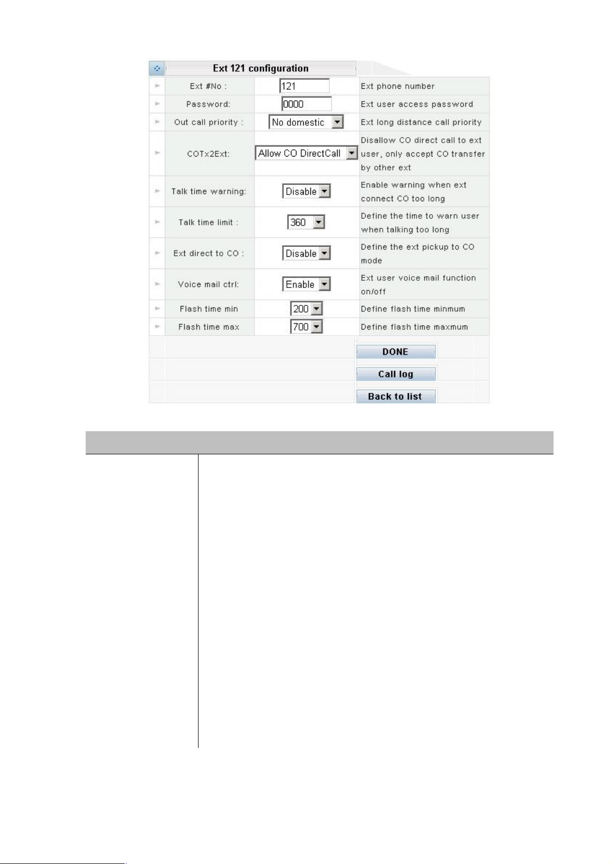
Please clicking Extension line telephone icon to enter into Ext xxx configuration:
Enable operator voicemail if the operator fails to answer the call.
IPX-1000 supports
DTMF after ring. Please check with
which type is used in your area. The caller ID information will be passed
through to the extension if Caller ID Pass Through function is enabled (
refer to “PBX config”).
CO line.
Page 53
49
The range is 100~899 and you are free to assign any number in this range to
e assigned the same number, the
physical port
number first. If that extension busy, the system will then try the one with the
Usage
You can restrict the outward dialing capability with this function if you also set
tem whether the dialed number is
Extension No.
Parameter Description
an extension. If two or more extensions ar
system will try to transfer the call to the one with the lowest
second lowest port number, and so on.
Password
Out Call Priority (Toll
Restriction)
Please insert the four-digit number. This password is used in the
Control function described below.
up the Toll Table. The Toll Table tells the sys
local, domestic long distance or international.
Unlimited:
No restriction at all.
No City Call:
Only internal dialing is allowed. No outward dialing is allowed.
No Domestic:
Only internal dialing and domestic local dialing are allowed.
No International:
All are allowed except international dialing.
Page 54
50
COTX2EXT (Incoming
CO Transfer)
If this feature is enabled, incoming CO calls can be transferred to this
unction).
extension directly. Therefore, the only way for an outside caller to talk to this
)
In order to prevent people from talking on the phone for too long, the system
is reached.
function,
Measured in seconds, this is the time the system will wait before playing the
If this function is enabled, you can pick up the phone and make an outside call
first. In this case, you will need
calling
Minimum flash time measured in milliseconds. A flash shorter than the
Maximum flash time measured in milliseconds. A flash longer than the
up instead of a flash.
extension by the system (via the auto attendant or the Ring Through f
If this feature is disabled, incoming calls cannot be transferred to this
extension is to call another extension (which allows Direct Inward Transfer
first, and ask to be transferred manually to this extension.
Talk Time Warning
(Usage Abuse
Reminder)
Talk Time Limit
(Usage Abuse Time)
EXT. Direct To CO
(Direct CO Access)
Voicemail Control
Flash Time Min.
Flash Time Max.
DONE
Clicking on the DONE button to apply the changes.
can be set up to play a reminder tone when the Usage Abuse Time
The call will then be disconnected forcefully in 30 seconds. This
however, does not apply to internal communications (extension to extension).
reminder tone as described above.
directly without pressing the CO Access Code
to press the “#” key first in order to access other system features or
other extensions.
ON: Turn on operator voicemail.
OFF: Turn off operator voicemail.
minimum flash time will be ignored. Recommended value is 100 ms.
maximum flash time will be considered as a hangRecommended value is 700 ms.
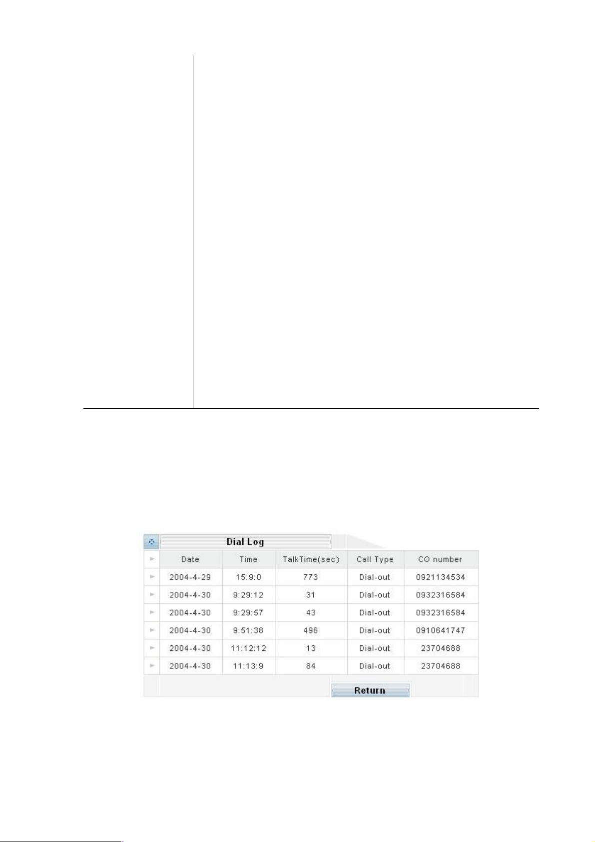
Call Details Log
Clicking here to access the Call Details Log. The Call Details Log keeps a record of all outside related
calling details (both inbound and outbound) for this extension in the past 7 days.
Back To List
Clicking here to return to the previous menu listing all CO and extension lines.
Page 55
51
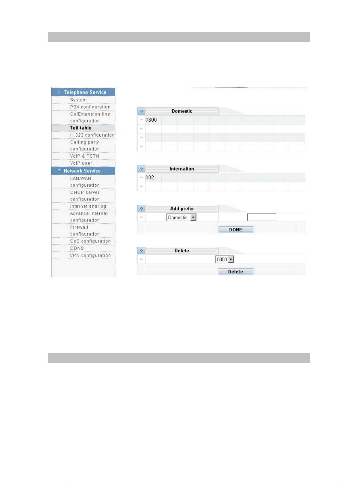
Toll Table
If you enable Local or Domestic toll restriction, you must set up the Toll Table so that the system knows
whether an outward dialing is local, Domestic long distance or international. When entering the prefix
digits, do not include the CO Access Code (the code that must be dialed before making an outbound
call). Please select the Toll table icon:
Add Prefix
Select either Domestic or International from the drop down list; enter the prefix in the blank box, and
clicking on the DONE button. Here Domestic means Domestic long distance.
Delete Prefix
Select the prefix from the drop down list and clicking on the DELETE button.
H.323 Configuration
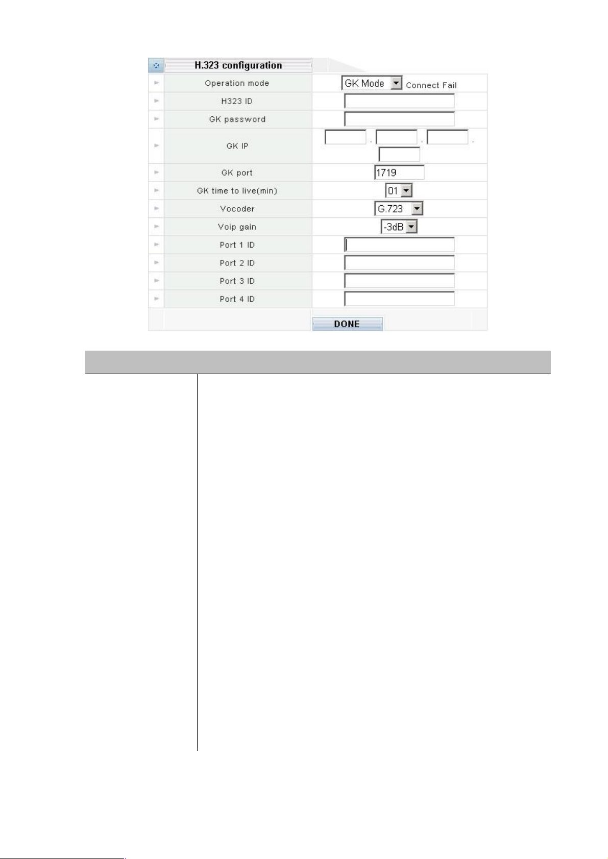
IPX-1000 supports the “H.323” VoIP phone standard. There are two modes of operation: P2P mode
and GK mode.
l The P2P mode allows for direct communication and is used when both parties have static IP
address.
l The GK mode is used when at lease one party has dynamic IP address. The Gatekeeper acts like
an address-translating middleman. Every time connects to the Internet; the PC will automatically
register with the Gatekeeper to let it know about current IP address. You can then communicate
with other members of the same Gatekeeper service.
Page 56
52
mode and GK mode, as described above. If you select
any Gatekeeper related items
You can restrict the outward dialing capability with this function if you also set
tells the system whether the dialed number is
the password that you need to register with (login) the
service provider if you
h
the port used by the Gatekeeper service. Consult with your
1000 results
echo when communicate with another VoIP device, you have to adjust
Consult with your Gatekeeper service
Parameter Description
Your choices are P2P
Operation Mode
H323 ID Please insert the name for your own reference.
the P2P mode, you don’t need to set up
described below.
Out Call Priority (Toll
Restriction)
GK Password
GK IP
GK Port
GK time to live (min) Gatekeeper searching time.
Vocoder Voice compression type.G.723.1 or G.729a.
VoIP gain
Port 1 ID, Port 2 ID
up the Toll Table. The Toll Table
local, Domestic long distance or international.
Please insert
Gatekeeper service. Consult with your Gatekeeper
don’t know.
Please insert the IP address of your Gatekeeper service provider. Consult wit
your Gatekeeper service provider.
Please insert
Gatekeeper service provider.
Alignment VoIP gain, default value is –3dB. For example, if IPX-
IPX-1000’s VoIP gain till the echo is disappear.
Please insert the ID for port 1 and 2.
provider if you don’t know.
Note that, in general, each port ID must be unique.
DONE
Clicking on the DONE button to apply the changes.
Page 57
53
Calling party configuration
select a mode to use when communicating
1000 and requires both parties to have static IP
1000, using this mode is highly
mode, their systems know more about each other’s capabilities. This mode
equires both parties to have static IP address. This mode is
You must use this mode if at least one party does not have static IP address.
eeper service with which both parties are
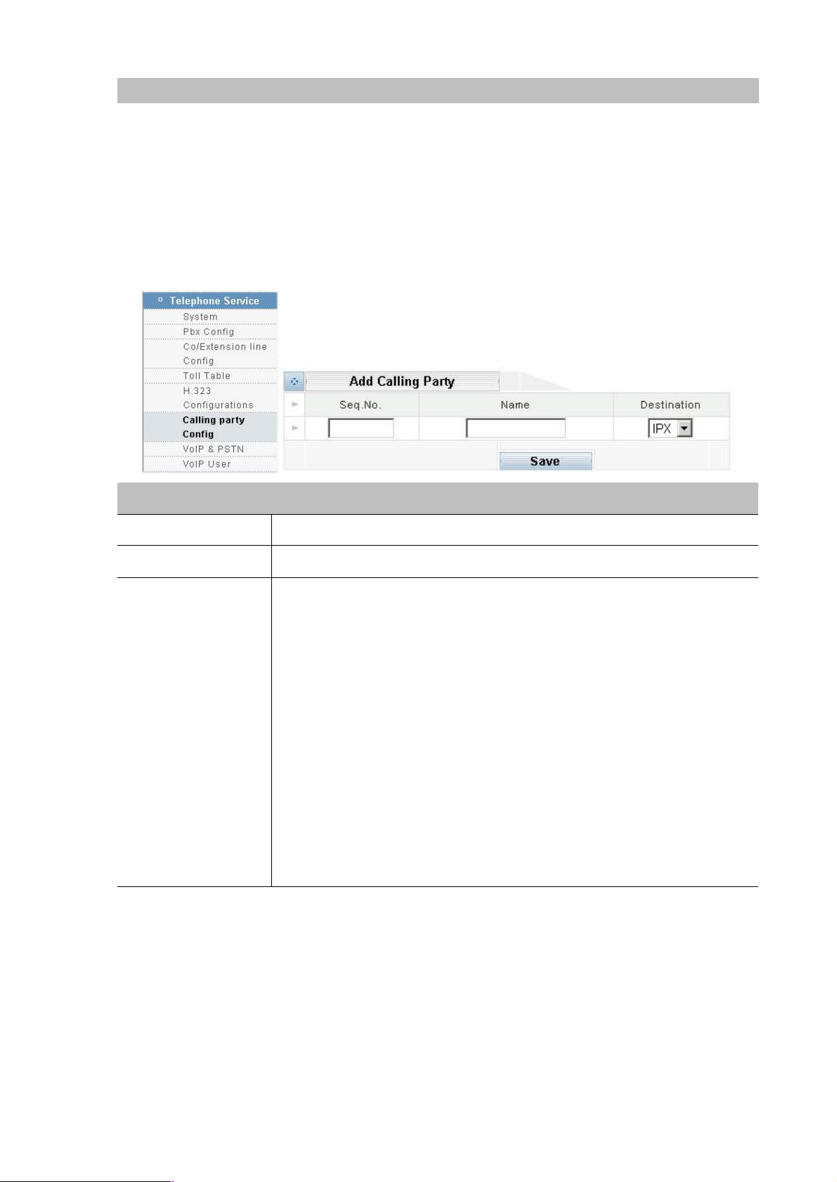
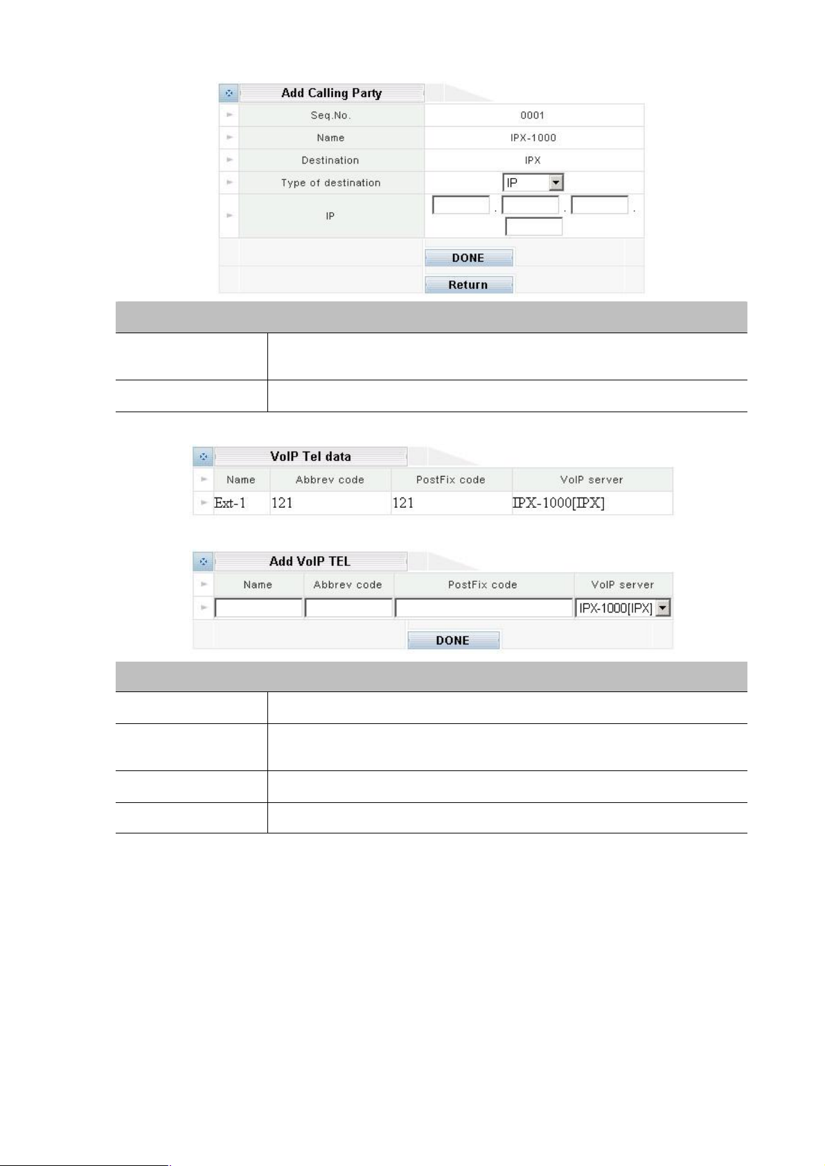
This is where you enter the details of all the VoIP servers that you want to communicate with. An IP
phone call involves two VoIP servers: your IPX-1000 and the VoIP server at the other end. Both VoIP
servers must be in the same mode when communicating with each other. Therefore, in addition to
setting up your own system properly, you must also advise the other party to set up their system with
the same mode. Here is a description on the three available modes.
Add Calling Party
Parameter Description
Seq No. Please assign a unique number to each server.
Name Please insert the name for your own reference.
From the drop down list, please
with this server.
IPX Mode:
This mode is unique to IPXaddress. If the other party also uses IPXrecommended but not mandatory. When two parties communicate in the IPX
Destination
DONE
Clicking on the DONE button to add an entry. A new menu will appear for you to enter the other
offers better Off-Net controls.
GW Mode:
This mode r
usually used when the other party uses an H.323 system other than IPX-1000.
GK Mode:
The call is made through a Gatek
registered.
server’s IP address or domain name.
Page 58
54
Parameter Description
to use when communicating with
That code is better defined as same as
Type of destination
IP/Domain Please insert the IP address or Domain name
Please click the Seq.No or Name link to enter into VoIP Tel data
From the drop down list, please select a type
this destination.
Parameter Description
Name Please insert the username of the remote extension
Abbrev code
Please insertthe number you dial (
remote extension number and different from local extension number)
PostFix code Please insert the number of the remote extension
VoIP server Please selection the destination device.
Page 59
55
VoIP & PSTN
Net calls with unknown
privilege is known if and only if the call is
of
Net calls have unknown privilege, therefore are regulated by this
Dialing Code to be consisted of a “9” followed by a
toll restriction
if the toll restriction of the
are not
not a virtual user of the remote office cannot
Dialing Code to be consisted of a “9” followed by
ere is no toll restriction for this
Password cannot make
Net calls,
this level. Use this level with caution because
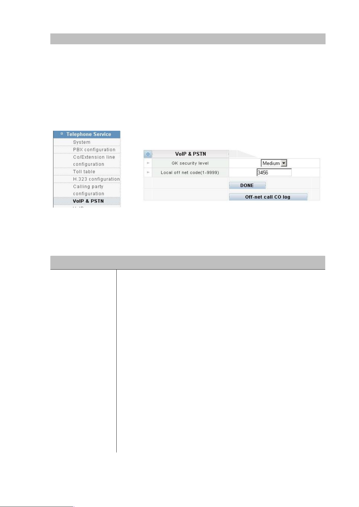
Based on the distributed architecture concept, VoIP extensions are off-premises extensions reachable
through VoIP calling party. You can call a VoIP extension by dialing a simple extension number as if
you are dialing a local extension, although the VoIP extension may be physically located in a remote
office thousands of miles away. Since the call is established via the Internet, voice quality may be
subject to network conditions. In addition to calling remote offices, you can also use VoIP extension to
go Off-Net – a way to make outbound calls from the remote office. The main reason for making Off-Net
calls is to save long distance charges. Please select the VoIP & PSTN icon:
GK Security Level
(Off-Net Security
Level)
Parameter Description
The Off-Net Security Level controls all incoming Offprivilege. An incoming Off-Net call’s
in IPX mode and originated from a remote extension. All other types
incoming Offsetting.
High:
This level requires the Postvalid Virtual User ID and Virtual User Password. The user’s
setting will restrict the Off-Net call. For example,
virtual user is set to “Local”, then the Off-Net call can only be made to local
numbers. If the toll restriction is set to “Internal”, then Off-Net calls
allowed. Also, people who are
make Off-Net calls via this office.
Medium:
This level requires the Postthe Local Off-Net Password (described later). Th
level. People who don’t know the Local Off-Net
Off-Net calls via this office.
Low:
This level requires just a “9” as the Post-Dialing Code to make Offand there is no toll restriction for
it allows virtually everyone to make Off-Net calls.
Page 60
56
Local off net code
Net Password which is
Net Privilege Level is set to
(Local Off-Net
Password)
Please select a four-digit number as the Local Offrequired to make Off-Net calls when the Off“medium” (as described above).
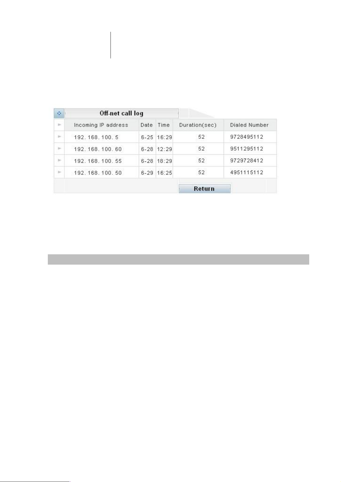
Off-net call CO log
Please clicking Off-net CO log button to view a log for all Off-net calls. The information includes
Incoming IP address, date, time, duration, and called number.
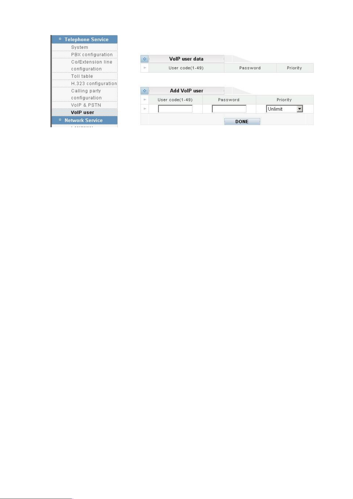
VoIP user
VoIP user date
VoIP user date is users who want to make Off-Net calls through this office. If the Off-Net Security Level
is set to high, a non-IPX Off-Net call will be allowed only if the caller is a VoIP User of this office. Up to
50 VoIP Users can be set up here.
User code (1~49)
Enter a unique three-digit number, ranging from 000 to 049.
Password
Enter a four-digit number, ranging from 0000 to 9999.
Priority (Privilege)
From the drop down list, select a privilege level you want to assign to this VoIP User.
DONE
Click on the DONE button to add the entry.
Page 61
57
Page 62

58
Appendix A: IPX-1000 Telephone Commands
CO (the central office line) Dialing Process
Dial
Hint
Dial
Hint
0: transfer to operator
When an inbound call is received, the system will play the System Greeting Message first. If
the caller dial “0” does not press any key during the entire period (both message playing and 3
second waiting time), the call will be transferred to an operator automatically.
*2 : the call will be transferred to the voicemail system.
Press “1” = leave a message
Press “2” = Mailbox Password (default value is “0000”)
“1” = hear new messages
“2” = hear old messages
“3” = change password
“4” = change Follow-Me setting
“5” = set Follow-Me number
When listening to the playback of a message or conversation, you may interrupt it by pressing
the Flash key or the Recall key on the phone.
Dial
Hint
EXT (extention) Dialing Process
Dial
Hint
100〜899 : the call will be transferred to local or remote(VoIP) extention
Transferred to local extention:
Dial the extention number during the greeting message.
Transferred to remote extention (VoIP):
Dial the extention number during the greeting message, and caller will hear the alert sound
“du-lu-ru” from system
9: the CO Access Code is set to be
User must dial “9” to request a CO line first. The request is permitted after hearing the CO dial
tone and you can start making the call. On the contrary, the request will be denied because all
lines are busy or the extension is not allowed to make outside calls, you will hear a message
to that effect.
Page 63

59
Dial
*2: entry major mode and voice-mail system.
Hint
Dial
Hint
Press “1” = leave a message
Press “2” = Mailbox Password (default value is “0000”)
“1” = hear new messages
“2” = hear old messages
“3” = change password
“4” = change Follow-Me setting
“5” = set Follow-Me number
When listening to the playback of a message or conversation, you may interrupt it by pressing
the Flash key or the Recall key on the phone.
*8:Call pickup
You can answer an incoming call that is ringing at another extension from your phone without
leaving your desk. The following types can pick up a extension’s call. Dial *8 when the other
extension is ringing.
Dial
Hint
Dial
Flash(100ms〜700ms)/Recall:Call transfer
How to transfer a call?
First, you should press the Flash key and the call will be hold on the line.
Second, dial the extension number and hang up.
The call will be transferred after finishing the two steps.
When the extension answers, you may talk to it before hanging up, too. The call will not be
transferred until you hang up.
If the extension is busy without voicemail or does not want to answer this call, you may cancel
the transfer by pressing the Flash key again. The call will then come back to you instead of
being transferred to the extension.
If the extension is busy with voicemail, the call will be transferred to its voicemail box
automatically. In this case you should hang up the phone immediately and let the caller hear
the personal greeting message.
#01〜#30: the personal command setting
Hint
If you use Planet IP-PBX system, there may have some of the useful personal phone
commands described below. Please refer to “Personal phone command manual” on page 52.
Page 64

60
Dial
#31XXXX〜#60XXXX:
Hint
Personal Phone Command List
command
The system command setting (where “XXXX” represents PCBX system’s password and the
default value is “1234”), please refer to “System phone commands manual” on page 52.
Feature Default
#01 Personal Voice Announce 1
Call Forwarding Setting
#02
#03
#04
#05
#06 Call Pickup Accept or Drop 0
#07
(0=cancel the forwarding;1=leave message;2=Walking Extension;
3=forward to outside party)
The function is reserved
The function is reserved
The function is reserved
Timed Reminder(MM.DD.HH.MM,8 digits)
0
0
#08
#09
#10
#11 Automatic Callback Busy (only for extension) 1
#12
#13
#14
#15
#16
#17 Time Service 0
#18
#19 Extension Number Directory 0
#20
The function is reserved
The function is reserved
The function is reserved
The function is reserved
The function is reserved
The function is reserved
The function is reserved
The function is reserved
The function is reserved
The function is reserved
Introduction of the Personal Command
Dial
#01: Personal Voice Announce
Page 65

61
Hint
Incoming calls that meet specific predefined criteria be answered automatically by your
extension. Enabling/Disabling according to the extension is set on the mode of “cancal the
forwarding” or “leave message”. You can enable or disable Voice Announce at any time. The
Voice Announce state is shown only if your extension is set on forwarding to your voicemail
box as explained on “#02” Call Forwarding Setting
#02: Call Forwarding Setting
Dial
Hint
Note
(0=cancel the forwarding;1=leave message;2=Walking Extension;3=forward to outside
party)
You can have your incoming calls forwarded to a specified destination by dialing “#02”. You
can set 4 modes after hearing the voice announce.
“0” cancel the forwarding.
“1” You can set the extension’s voice mail as a forward destination. When extension receive
incoming call, outside party will hear the personal voice announce you recorded before and
will be ask for leaving message.
“2” You can set another extension as the forward destination. When extension receive
incoming call, outside party will be transfer to the extension appointed to forward.
“3” You can set your mobile telephone as the forward destination when you go outside the
office. When extension receive incoming call, system will catch a CO line and will transfer the
call to the phone number you set before.
You have to ask your administrator to open the function of. If you discover your extension is
limited, please chech the setting in Toll Table function.
Dial
Hint
Dial
Hint
#07: Timed Reminder(MM.DD.HH.MM,8 digits)
Please dial “#07” to set alarm according to
Month (01~12) two digit.
Day (01~31) two digit.
Hour (00~23) two digit.
Minute (00~59) two digits.
You can receive an alarm at your telephone to remind you of a meeting, appointment or as a
wakeup call. When you go off–hook to answer; you will hear the time announced by system or
your prerecorded message. The alarm will keep ringing in 30 second. If you don’t answer
during this time, the IPX system will save the prerecorded message in the voicemail and
enable the light of the phone at the same time.
#11: Automatic Callback Busy(only for extension)
You can dial “#11” to set the other extension to receive callback ringing when the extension
Page 66

62
becomes idle.
Your extension will starts ringing automatically when the extension you set answer the
callback ringing.
Dial
Hint
Dial
Hint
System Phone Command List
System Phone Command Setting (XXXX is the password of the PCBX system,and the default value is
“1234”;You have to dial the password after dialing command)
Command
#17: Time Service
You can check the current time of the system by dialing “#17”
#19: Extension Number Directory
You can check the extension number by dialing “#19”, and the system will display the
“physical number of the extension”, “group number”, “extension number” in turn. It’s very
convenient to set up IPX machine at the beginning by using this function.
Feature Default
#30
PBX Password Changing 0
#31
#32
#33
#34
#35
#36
#37
#38
#39
#40
#41
#42
#43
The function is reserved
The function is reserved
Reset to Default Value 0
The function is reserved
The function is reserved
The function is reserved
The function is reserved
The function is reserved
The function is reserved
The function is reserved
The function is reserved
The function is reserved
Off Duty Greeting Record 0
#44
#45
The function is reserved
The function is reserved
Page 67

63
#46
The function is reserved
#47
#48
#49
#50
#51
#52
#53
Introduction of the System Command
The detail explain about the command (You have to add system’s password behind the command to
finish the setting)
Dial
Hint
#30:Password Changing(4 digit)
You can assign a password for IPX system by dialing “#30XXXX”. The voice will ask you to
The function is reserved
The function is reserved
On Duty Greeting Record 0
The function is reserved
The function is reserved
The function is reserved
The function is reserved
Dial
Hint
Dial
Hint
enter 4-digit number to change the factory value of the system.
#33:Reset(S:0=reset the password to ‘0000’;S:1=clear the data and setting of the
extension)
The command “#33XXXX” is used to clear the data like recording and voice mail on your
extension. There are two selections. “0” is changing the extension’s password to the default
value “0000”, but keep the data and setting on the extension. “1” is not only change the
password to default value “0000” but all information will be changed to factory value that
include recording and voice mail.
#43:Record/Review Off-Duty System Greeting Message
Maximum recording time is 60 seconds. When you are finished, carefully hang up the phone
in order to minimize the noise at the end. To review the off-duty system-greeting message,
enter “#43” alone without the system password. The message will be played after about 2
seconds.
Dial
Hint
#49:Record/Review On-Duty System Greeting Message
Maximum recording time is 60 seconds. When you are finished, carefully hang up the phone
in order to minimize the noise at the end. To review the off-duty system-greeting message,
Page 68

64
enter “#49” alone without the system password. The message will be played after about 2
seconds.
Introduction of the Useful Command
How to listen your voice mail?
Hint
Note
On your desk à dial “*2” à follow the process system ask
At the other desk à dial “*2” à enter your extension number à follow the process system
ask
At the outside party à after hearing IVR, please dial “*2” à enter your extension number à
follow the process system ask
The process of enter the voice mail:
Dial “1”:leave the massage for master.
Dial “2”:reserve for master à
“2”:listen the voice mail;
“3”:change extension’s password;
“4”:call forward set;
“5”:enter the forwarded number
(The default password value is “0000”, and when you listen the voice mail, you can use
“Recall” or “Flash” to disconnect forced)
Dial “###” to finish Last Number Redial
Hint
Hint
This is convenient when calling the same outside party again.
How to transfer the call to another extension?
(1) Talk à dial “Flash” or “Recall” à dial the extension number you want to transfer to à off
hook after talking to extension or the extension is busy à dial “Flash” or “Recall” again à
receive the talking to the call wanted to be transfer
(2) Talk à dial “Flash” or “Recall” à dial the extension number you want to transfer to à talk
to the extension à off hook à transfer the call to the destination
(3) Talk à dial “Flash” or “Recall” à dial the extension number you want to transfer to à off
hook à transfer the call to the destination (the call will be transfer to voice mail or operator if
the extension is busy)
How to record you’re personal voice announce?
Page 69

65
Hint
On your desk
At the other desk
follow the process system ask
At the outside party
your extension number
Dial
voice announce from
Hint Off hook à dial “#33XXXX” à enter your extension number+“0”à finish
Off hookà dial “#01”à record after hearing “beep” alarm à record your personal voice
announce à on hook carefully
How do you do if you forget your extension password?
NOTE
Hint
If you enter your extension number+“1” after dialing the command, all of the data and setting
including the voice mail will be clear. So you have to use this function carefully.
How to set your time alarm?
Off hook à dial “#07” à enter month, day, hour and minite totally 8 digit (For example: you
have to dial "01021520” to represent January 2, 3 o’clock and 20 minite pm)à you can on
hook directly or on hook after recording the message.
Introduction of the *key
* Key
*1
*2
Function Method
Reserved
Voice mail and
Master mode
à dial “*2” à follow the process system ask
à dial “*2” à enter your extension number à
*3
*4
Record personal
outside party
Reserved
à after hearing IVR, please dial “*2” à enter
à follow the process system ask
The process of enter the voice mail:
Dial “1”:leave the massage for master.
“2”:reserve for master à
“2”:listen the voice mail;
“3”:change extension’s password;
“4”:call forward set;
“5”:enter the forwarded number
*3 + system’s password
Page 70

66
*5
H323 ID mode
Dial
*6
dialing
GW mode dialing
*5 + “another machine’s port ID registered on the same
GateKeeper” + “# key”
To ring the remote GW; IP-Phone or the operator of IPX machine.
Example: you can dial *5 13023886798 # to ring the remote GW;
IP-Phone or the operator of IPX machine.
Dial
*5 + “another machine’s port ID registered on the same
GateKeeper” + “the extension of the IPX machine” + “#key”
To ring the remote GW; IP-Phone or the operator of IPX machine.
Example: you can dial *5 13023886798 177 # to ring the 177
extension of IPX machine register under the same GateKeeper.
Dial
*6 + “No. In the VoIP Server selection” + “the extension of that
machine” + “# key”
To ring the remote extension speedy through VoIP.
*7
*8
*9
*0
Example: you can dial *6 0001 177 # to ring the 177 extension of
Dial
*6 + “No. In VoIP Server selection” + “# key”
To ring the operator of the remote IPX Series machine through VoIP.
Example: you can dial *6 0001 # to ring the operator of No.0001
IPX machine in VoIP Server selection.
Speed dial
Call Pickup
Reserved now
Pick up incoming call ringing at the other extension
Reserved
Reserved
No.0001 machine in VoIP Server selection.
Page 71

67
Appendix B: Specifications
Model IPX-1000
Dimensions (mm) 215 (L) x 30 (H) x 132 (W)
Operating Temperature 0~50 degree C, 10~90% humidity
VoIP Standard H.323,
Compression G.723/G.729
Echo Cancellation G.165/G.168 25ms
Network Protocol: TCP/IP, NAT, DHCP, HTTP, DNS
Network Interface: LAN 4 * 10/100 Mbps RJ-45
Network Interface: WAN 2 * 10/100 Mbps RJ-45
Power Adapter 12 V, 3.3A
 Loading...