

Pitney Bowes DA80F, DA95F, WF81, WF96 Service Manual
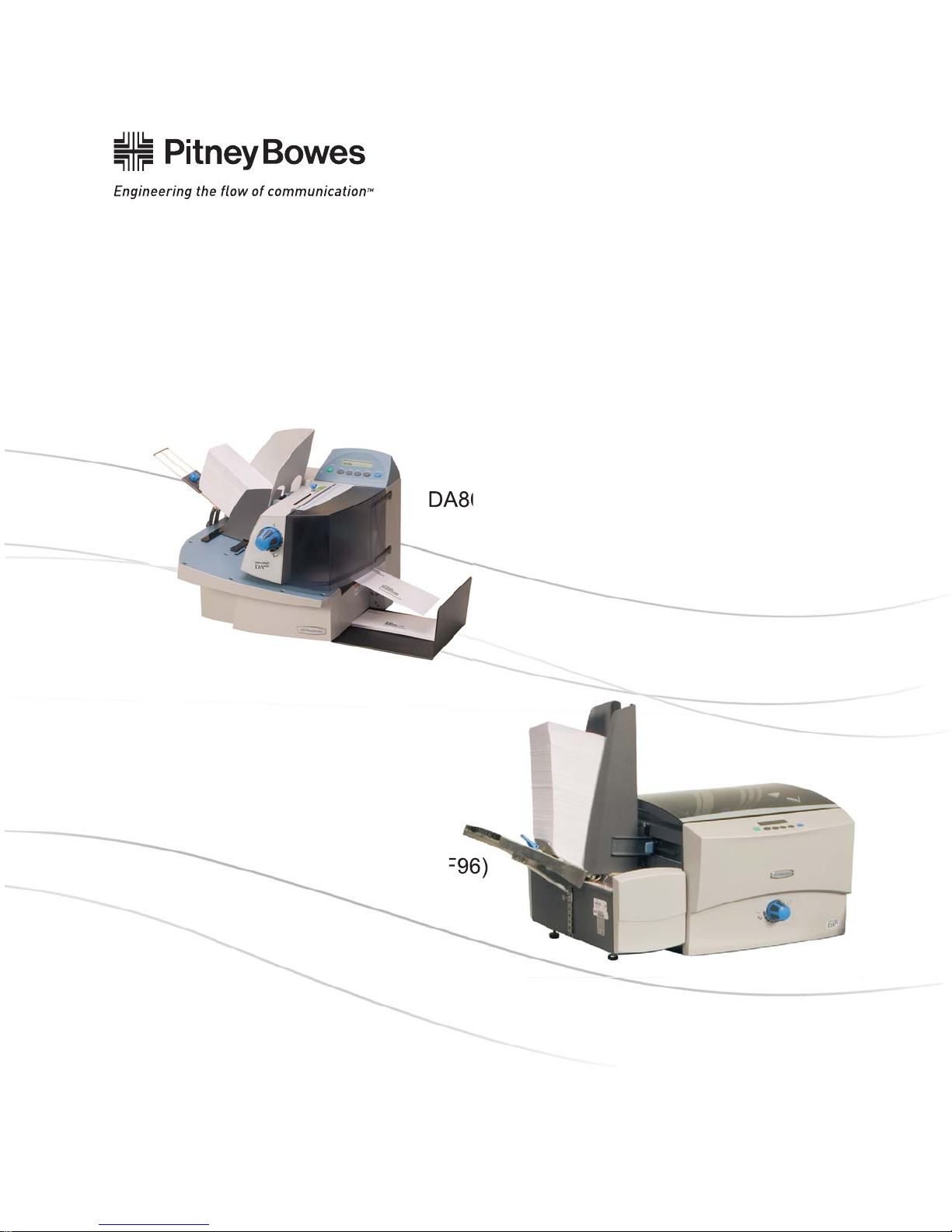
DA80F and DA95F
AddressRight™ Fixed Head Printers
DA80F (WF81)
DA95F (WF96)
Service Manual

FCC Compliance
This equipment had been tested and found to comply with the limits for a Class A digital device,
pursuant to Part 15 of the FCC rules. These limits are designed to provide reasonable protection
against interference when the equipment is operated in a commercial environment. This equipment
generates, uses, and can radiate radio frequency energy, and if not installed and used in accordance
with the users manuals, may cause harmful interference to radio communications. Operation of this
equipment in a residential area is likely to cause harmful interference in which case the user will be
required to correct the interference at his own expense.
Shielded cables must be used with this unit to insure compliance with Class A limits.
Canadian DOC Compliance
This digital apparatus does not exceed in the Class A limits for radio noise emissions from digital ap-
paratus set out in the Interference-causing Equipment Regulations (Standard ICES-003) of the Canadian Department of Communications.
Le present appareil numerique n’emet pas de bruits radioelectriques depassant les limites applicables aux appareils numeriques de la class A prescrites dans le Reglement sur le brouillage radioelectrique edicte par le ministere des Communications du Canada.
NOTE: This equipment has been tested and found to comply with the U.S. Standard for Safety
UL1950, Third Edition, Safety of Information Technology Equipment including Electrical Business
Equipment and Canadian Standards C22.2 No 950-95, Third Edition, Safety of Information Technology Equipment including Electrical Business Equipment
First Edition, December 2007
SV61962 Rev. A
©2007 Pitney Bowes Inc.
All rights reserved. This book may not be reproduced in whole or in part in any fashion or stored in a
retrieval system of any type or transmitted by any means, electronically or mechanically, without the
express written permission of Pitney Bowes Inc.
We have made every reasonable effort to assure the accuracy and usefulness of this manual, however, we cannot assume responsibility for errors or omissions or liability for the misuse or misapplication of our products.

Table of Contents
Chapter 1 – Introduction
1.1 Purpose of this Manual .............................................................. 1-1
1.2 Related Publications .................................................................. 1-1
1.3 Book Organization ..................................................................... 1-2
1.4 Safety ........................................................................................ 1-2
Chapter 2 – Specifi cations
2.1 Product Description ................................................................... 2-1
2.2 System Requirements ............................................................... 2-1
2.3 Physical Equipment Specifications ............................................ 2-2
2.4 Print Specifications .................................................................... 2-3
2.5 Material Specifications............................................................... 2-7
Chapter 3 - Theory
3.1 Changes From Earlier Models .................................................. 3-1
3.2 Printer Architecture .................................................................... 3-2
3.3 Operating Sequence.................................................................. 3-6
Chapter 4 - Troubleshooting/Diagnostics
4.2 Block Diagrams ........................................................................ 4-2
4.3 Main Controller Board Diagnostics ........................................... 4-4
4.4 Error Codes ............................................................................... 4-9
4.5 Print Samples for Troubleshooting .......................................... 4-12
4.6 Feeding Issues ........................................................................ 4-14
4.7 Printing Issues ......................................................................... 4-19
4.8 Display Issues ......................................................................... 4-23
4.9 Miscellaneous Issues .............................................................. 4-23
DA80F/DA95F AddressRight™ Printers Service Manual (SV61962 Rev. A)
iii

Table of Contents
Chapter 5 - Removal & Replacement
5.1 List of Procedures...................................................................... 5-1
DA80F (WF81) Parts Removal
5.2 Rear Cover and Keyboard/LCD Display Board ......................... 5-3
5.3 Main Processor Board ............................................................... 5-4
5.4 Encoder Assembly .................................................................... 5-6
5.5 Paper Top Sensor Assembly (Emitter) ...................................... 5-9
5.6 Paper Bottom Sensor Assembly (Receiver) .............................. 5-9
5.7 Feeder Sensor Assembly (Emitter and Receiver) ................... 5-10
5.8 Front Bottom Cover Assembly ..................................................5-11
5.9 Transport Timing Belt .............................................................. 5-12
5.10 Feed Motor Timing Belt ......................................................... 5-13
5.11 Feed Roller Pulley and Feed Roller Assembly ...................... 5-14
5.12 Feed Motor Assembly and Encoder Harness Assembly........ 5-16
5.13 Transport Motor Assembly ..................................................... 5-18
5.14 H-Block Assembly (Media Separators) .................................. 5-20
5.15 Print Head Cables and Print Head Boards ............................ 5-21
5.16 Entry Idler Roller Arm ............................................................ 5-28
5.17A Feed Deck ............................................................................ 5-30
5.17B Front Plate Assembly ........................................................... 5-32
5.18 Transport (Metal Grit) Roller .................................................. 5-34
5.19 Exit (Rubber) Roller ............................................................... 5-35
5.20 Power Supply ........................................................................ 5-36
5.21 Print Head Access Door ........................................................ 5-38
DA95F (WF96) Parts Removal
Standard Feeder (WF9S)
5.22 Rear Cover/Side Guides ....................................................... 5-39
5.23 Lower Sensor Receiver Assembly ......................................... 5-41
5.24 Feeder Top Sensor (Emitter) Assembly ................................. 5-42
5.25 “H Block” Roller (Media Separator) ...................................... 5-43
5.26 Feed Belts and Rollers .......................................................... 5-44
5.27 Motor/Drive Assembly............................................................ 5-46
iv DA80F/DA95F AddressRight™ Printers Service Manual (SV61962 Rev. A)

Table of Contents
Chapter 5 - Removal & Replacement (continued)
DA95F (WF96) Parts Removal
Printer Section
5.28 Printer Top Cover ................................................................... 5-48
5.29 Front Cover and Keyboard/LCD Display Board..................... 5-49
5.30 Rear Cover and Processor Board ......................................... 5-51
5.31 Paper Sensor and Sensor Bar............................................... 5-54
5.32 Entry Roller Support Assembly .............................................. 5-55
5.33 Intermediate Idler Rollers Assembly ...................................... 5-56
5.34 Idler Roller Support (“Module A”) Assembly .......................... 5-57
5.35 Idler Roller Support (“Module B”) Assembly .......................... 5-58
5.36 Print Head Cables and Print Head Boards ............................ 5-59
5.37 Belt Drive Assembly............................................................... 5-67
5.38 Media Belts ............................................................................ 5-69
5.39 Encoder Assembly ................................................................. 5-71
5.40 Drive Belt/Motor Assembly .................................................... 5-74
5.41 Power Supply ........................................................................ 5-75
Chapter 6 - Adjustments
6.1 List of Adjustments ................................................................... 6-1
Adjustments for All Models
6.2 LCD Display .............................................................................. 6-2
6.3 Feeder Sensor Test and Calibration ......................................... 6-2
DA80F (WF81) Adjustments
6.4 Leveling the Print Head Assembly to Deck (Belts) .................. 6-3
DA95F (WF96) Adjustments
6.5 Leveling the Print Head Assembly to Deck............................... 6-5
6.6 Adjustable Thickness Knob and Eccentric Sprockets ................ 6-6
Chapter 7 - Maintenance Procedures
7.1 General Maintenance ................................................................ 7-1
7.2 Specific Maintenance ............................................................... 7-2
DA80F/DA95F AddressRight™ Printers Service Manual (SV61962 Rev. A)
v

Table of Contents
Appendix A – Printer Control Panel Menus and Utilities
A.1 Control Panel Menus for the Printer ..........................................A-1
A.2 LCD Control Panel Menu .........................................................A-3
A.2 LCD Main Menu .......................................................................A-4
A.3 LCD Setup Menu ......................................................................A-9
A.4 LCD Service Menu ................................................................. A-19
A.5 Setting Factory Defaults (from LCD Menu) ............................. A-24
A.6 Updating Firmware .................................................................A-26
Appendix B – Printer Communications
B.1 Communication Scenarios ........................................................B-1
B.2 Troubleshooting Tables .............................................................B-4
B.3 Testing Printer Communications Within a Network ...................B-6
Appendix C – Schematics
Main Processor Board for Both Printers ...........................................C-2
DA80F (WF81) Printer Block Diagram .............................................C-3
DA95F (WF96) Printer Block Diagram .............................................C-4
Appendix D – Print Head Alignment
D.1 Reason for this Appendix ..........................................................D-1
D.2 Print Head Alignment Procedure...............................................D-2
Appendix E – Printing Standards
E.1 USPS® Delivery Point Barcode (DPBC) ...................................E-1
E.2 USPS® PLANET Code Barcode ...............................................E-3
Index ..........................................................................I-1
vi DA80F/DA95F AddressRight™ Printers Service Manual (SV61962 Rev. A)

1 • Introduction
1.1 Purpose of
this Manual
1.2 Related
Publications/
Information
This manual contains instructions for troubleshooting and site repair of DA80F
(WF81) and DA95F (WF96) AddressRight™ fixed head printers. It also includes
complete product specifications and a section on theory for training purposes.
For reference, the table below shows the predecessor fixed head models.
New
Marketing
Model
DA80F WF81 Black and
DA95F WF96 Black and
DA80F Operator Guide SV61722
DA80F Parts List SV62033
DA95F Operator Guide SV61749
New
PCN
Printing
Capability
spot color
spot color
Speed Predecessor
Marketing
Model
Up to 22,000
#10 or DL
envelopes
per hour
Up to 30,000
#10 or DL
envelopes
per hour
DA400 W400
DA950 W803
Predecessor
PCN
DA95F Parts List SV62034
DA80/DA95F Hardware Install (US/Canada only) SV61747
DA80/DA95F Hardware Install (outside of US/Canada) SV61774
AddressRight Printer Drivers and
Envelope Designer™ Plus Software Install SV61108
Customer Tutorial for Setting up a DAxxx Series Printer
Using the AddressRight Printer Control Panel Application SV61986
For other information on the printers, refer to these sources:
• Software Control Panel Application (on the host PC) - see the help sys-
tem on the software.
• FAQs document - see the Customer Service website under the product
page for AddressRight™ printers.
• Training - see Enhanced AddressRight™ Fixed Head Printers Self-Directed Course (GMS-MC-03248) at My Portfolio on the Pitney Bowes intranet.
• Training Job Aids - print the job aids for the software control panel appli-
cation (GMS-MC-03248JA) at My Portfolio on the Pitney Bowes intranet.
DA80F/DA95F AddressRight™ Printers Service Manual (SV61962 Rev. A)
1-1

1 • Introduction
1.3 Book
Organization
1.4 Safety
Chapter 1: Introductory and safety information
Chapter 2: Product specifications
Chapter 3: Theory of operation
Chapter 4: Troubleshooting and Diagnostics
Chapter 5: Removal and replacement procedures
Chapter 5: Adjustment procedures
Chapter 7: Maintenance procedures
Appendix A: Printer Control Panel Menus
Appendix B: Printer Communications
Appendix C: Schematics/Diagrams
Appendix D: Print Head Alignment
Appendix E: Printing Standards
Warning messages appear throughout this manual to alert you to potentially
hazardous con di tions. Two designations indicate their relative seriousness:
WARNING! Calls attention to improper practices that
could result in a potentially serious, even lethal injury to
you or the customer.
CAUTION! Calls attention to practices that could
cause minor injury to you or a customer or that could
damage equipment or material.
Familiarize yourself with proper procedures and methods before you install,
operate or re pair the equipment to avoid personal injury or damage to the
equipment. If you train service peo ple or equip ment operators, it is important to
explain safety precautions to your students and en cour age safety awareness.
Personal Safety
Follow these precautions for your own safety:
• Treat every circuit like a gun that may be loaded. It may not be “live,” but be
sure. Check with a neon tester or voltmeter, or simply unplug the machine.
• Know how to turn off power in the work area and get help in an emer gen cy.
• Don’t un der es ti mate the danger of shock: 1 mA (1/1000 amp) is un com fort able; 5 mA is dan ger ous —you may jump back and be injured; 12 mA
causes hand muscles to con tract, so you can not free your self; 24 mA has
proven fatal; and 100 mA (1/10 amp) is likely to be fa tal.
1-2 DA80F/DA95F AddressRight™ Printers Service Manual (SV61962 Rev. A)

Introduction • 1
1.4 Safety
Personal Safety (continued)
• Don’t work on equipment under power unless it’s absolutely necessary.
If you must, use extreme cau tion. Don’t grasp two sides of a live circuit
at the same time—use one hand when reach ing into a cir cuit, touching
a ground ed case or chas sis with that wrist or el bow if pos si ble. This pre vents cur rent from passing through vital organs. Observe this rule when
con nect ing or dis con nect ing plugs or leads, or mak ing any adjustments
on a live cir cuit.
• Use the right tools for the job. A tool which slips can cause a short—or a
shock. Don’t reach into a circuit with metal tools, or while wearing rings or
a watch. Even in low voltage cir cuits, a metal object can short circuit two
terminals. When work ing on live cir cuits, use tools with in su lat ed handles
and try to keep your tool hand grounded.
• Don’t bypass safety devices, particularly fuses. Three-wire outlets (120
Vac) are designed to ground equipment to make it safe. If a hot wire
shorts to a grounded frame, the only result is an open fuse. If a hot wire
shorts to an ungrounded frame, the frame itself be comes hot and po ten tial ly dangerous. A fuse is a weak link in a circuit, de signed to break down
before any thing else does. The maximum safe cur rent in a circuit is de ter mined by the de sign ers. Too large a fuse can pass excessive current,
dam ag ing expensive equipment.
• For electrical fires, use Type C, BC or ABC extinguishers only. Don’t use
soda acid or other liq uid stream extinguishers. They will damage elec tri cal equipment and present a shock hazard to the user.
• Digital equipment can be easily damaged or destroyed by static charges.
Mi cro pro ces sors and other integrated circuits con tain tiny transistors not
much more than a mil lionth of an inch across, which operate at 5 to 12
volts.
• Be extremely careful when lifting heavy equipment. Follow the guidelines
below:
a. Squat to lift and lower. DO NOT bend at the waist.
b. Keep your low back bowed in while bending over.
c. Keep the weight as close to you as possible.
d. Bow your back in and raise up with your head first.
e. If you must turn, turn with your feet, not your body.
f. Never jerk or twist!
g. Put the weight down by keeping your low back bowed in.
h. Keep your feet apart, staggered if possible.
i. Wear shoes with non-slip soles.
j. Get help if you need it.
DA80F/DA95F AddressRight™ Printers Service Manual (SV61962 Rev. A)
1-3

1 • Introduction
1.4 Safety
Electrostatic Discharge (ESD) Procedures
Follow these guidelines to protect sen si tive equipment from static damage:
• Always use a wrist grounding strap and anti-static mat when working on
equipment sensitive to electrostatic discharge. These items are furnished
in the ESD Field Service Kit, L-8351.
• Ground yourself before reaching into the equip ment, or touch ing any
circuit board or other electrical component. Just touch ing a doorknob or
metal work bench may be enough, but the best guarantee is to turn the
machine off but leave it plugged in, and ground your self on the chassis,
which is grounded through the three-wire power cord.
• Be careful of rugs—even a few steps can recharge you. Re-ground yourself whenever you’ve walked away and re turned to the ma chine. Rugs
are a major source of static build up in the body.
• Take greater precautions as the objects you handle get smaller. A board
in the machine is better protected than one that is not plugged in; a chip
on a board is better protected than one in your hand.
• Stay away from metal conductors. The plastic and resin that chips and
boards are made of are much better insulators than metal. It’s most important to keep your hands away from any metal which contacts the data.
In particular, this means the long connector along the bottom of each
board, and the pins coming out of the chips. These signal and data lines
are directly connected to the fragile inner circuits of the chips. When handling a board, try not to touch the connector; when handling a chip, try
not to touch the pins.
1-4 DA80F/DA95F AddressRight™ Printers Service Manual (SV61962 Rev. A)

2 • Specifications
2.1 Product
Description
2.2 System
Requirements
The DA80F (WF81) and DA95F (WF96) ink jet printers are fixed head type
desktop models used to print addresses, graphics and other information, in
black ink and spot color on a wide range of material sizes, construction and
composition. The operator can define the font, placement, print quality and bar
code characteristics for the printed addresses.
Customer PCs must meet the following minimum requirements:
• CPU: Pentium III 500MHz. or greater, 500MB RAM or more preferred
• USB Cable/Ethernet Cables cable are supplied with the printer. If the
customer chooses to use another USB cable, it must be no longer than
15 feet (5 meters).
• Windows 2000 SP4, Windows XP Pro SP2, Windows Server 2003 SP1
w/latest Service Pack, and Windows Vista
• Dot Net v2.0
• 5MB Disk space
• Administrative rights to install software
2.3 Physical
Equipment
Specifications
Physical Dimensions
DA80F
17.9" (455mm) high; 18.5" (470mm) wide; 17.7" (450mm) deep
DA95F:
15” (380mm) high; 24” (609.6mm) wide; 27” (685.8mm) deep
Weight
DA80F:
53 lbs. (24 kg), including print cartridges and output stacker.
DA95F:
88 lbs. (39.9 kg), Feeder 28 lbs. (12.7 kg), Printer/Feeder 116 lbs. (52.6 kg)
Electrical
Domestic: 100-240 VAC, 50/60 Hz, 5.0 A
Power Consumption: 575 Watts, 1962 BTU/hr.
Agency Approvals
TUV/UL/cUL/VDE-GS - Refer to the FCC and CE statements at the front of
this manual for more information.
DA80F/DA95F AddressRight™ Printers Service Manual (SV61962 Rev. A)
2-1

2 • Specifications
2.3 Physical
Equipment
Specifications
Interface
USB, Ethernet
Control Language
PCL5, enhanced
Environmental Limits
Operating Conditions and Longterm Storage
• Temperature: 55 to 95°F (10 to 35°C)
• Humidity: 8 to 80%
• Maximum Wet Bulb Temperature: 80°F (27°C)
Shipment Conditions
• Temperature (Printer): -4 to 140°F (-20° to 60°C)
• Humidity (Supplies): 5 to 85%
• Maximum Wet Bulb Temperature: 85°F (29°C)
Noise Level
DA80F
The sound pressure level at the operator’s position for this equipment as measured in any mode using ANSI and ISO Standards is no more than 75 dB(A).
DA95F
The sound pressure level at the operator’s position for this equipment as measured in any mode using ANSI and ISO Standards is no more than 76 dB(A).
2-2 DA80F/DA95F AddressRight™ Printers Service Manual (SV61962 Rev. A)

Specifications • 2
2.4 Print
Specifications
Print Modes (Print Resolution)
The printers have four print resolutions; they are Executive (600 DPI), Letter
(300 DPI), Draft (200 DPI), and Super Draft (150 DPI), which represent the
horizontal density. Additionally, there are two Light Mode settings (ON and
OFF), which represent the vertical density. When Light Mode is “ON”, the
vertical density setting is 300 DPI; when Light Mode is “OFF” the vertical density setting is 600 DPI. Refer to the table below for print mode options.
Print Quality With Light Mode set to
"ON"
Executive 600 x 300 DPI 600 x 600 DPI
Letter 300 x 300 DPI 300 x 600 DPI
Draft 200 x 300 DPI 200 x 600 DPI
Super Draft 150 x 300 DPI 150 x 600 DPI
With Light Mode set to
"OFF"
Fonts
Resident Fonts
Arial, Comic Sans MS, Courier New, Georgia, Impact, Kino, MSLogo, Symbol, Tahoma, Times New Roman, Trebuchet MS, Verdana, Webdings, Wingdings, plus there must be included one OCR and one Code 39 font. (All fonts
are scalable from 4 to 108 pt size.)
Resident Font Enhancements
Bold, Underline, Italic
Downloadable Fonts
Supports TrueType and Bitmapped fonts.
Downloadable Graphics
Supports Bitmap and PCL Raster images up to 40 sq in. (258 sq. cm). This
translates to images up to 3" x 13.3" (76mm x 338mm) for the DF95.
User-Definable Parameters
• Font Characteristics
• Address Placement
• Barcode Characteristics
• Print Quality
Barcode Printing Position
The printer can print a barcode in one of three positions:
• Above the address block
• Below the address block
DA80F/DA95F AddressRight™ Printers Service Manual (SV61962 Rev. A)
2-3

2 • Specifications
2.4 Print
Specifications
✍
TIP: Do not attempt
to print "high density"
barcodes, that is, those
barcodes whose narrow elements are less
than 0.010" (.254mm).
Barcode Printing Types Position
All the printers in the DA Series can print the following barcodes:
1-Dimensional
• USPS Certified POSTNET barcode. All types of barcodes can be printable including FIM, 3 of 9, 4 state barcode (USPS, UK, Canadian, Euro,
Australia, etc.) and others.
• Planet barcode for delivery confirmation services.
• The printer is also capable of printing any barcode rendered by a Windows® True Type font.
2-Dimensional
The printers are capable of printing a USPS Certified IBIP barcode as well as
all types of 2-D barcodes defined for the UK, Canada, Europe, Australia, etc.,
and others to the defined standards. Reference applicable Postal Standards.
NOTE: Do not attempt to print "high density" barcodes. The narrow elements
should not be less than 0.010" (.254mm).
Special Note on FIM Barcode
FIM (Face Identification Marking) barcode was developed by the USPS as
part of their POSTNET barcoding system. It is normally used by high-volume
mailers to put on return envelopes for their customers’ invoices.
When the invoices are mailed back in their return envelope, the USPS sorts
and processes this mail according to what version of FIM barcode is used on
the envelope: FIM A (Postage required, POSTNET bar code included), FIM
C (Postage prepaid, POSTNET bar code included), and FIM D (Postage required, POSTNET bar code not included).
One of the requirements of the FIM barcode is that it needs to be printed on
the edge of the envelope (typically printed in the top right corner). Any attempt to print to the exact edge of the envelope is liable to "miss" the edge
occasionally. Because of these issues, we cannot guarantee full USPS
compliance for printing FIM barcode. As a result, some of our high-volume
customers used pre-printed envelopes containing the FIM barcode that meet
USPS printing specifications.
However, if you want to try printing the FIM using our printers, the Pitney
Bowes Envelope Designer Plus software allows you to place a FIM graphic
on the envelope. You can obtain photo-ready graphics directly from the
USPS (the Envelope Designer software itself can not create the FIM barcode
graphic).
2-4 DA80F/DA95F AddressRight™ Printers Service Manual (SV61962 Rev. A)
Specifications • 2
2.4 Print
Specifications
Effective Print Area
The printable width is the width of the piece measured from the right side of
the piece of mail. The printable height is 1.5" (38mm) for the DA80F and 3”
(76mm) fro the DA95F.
NOTES:
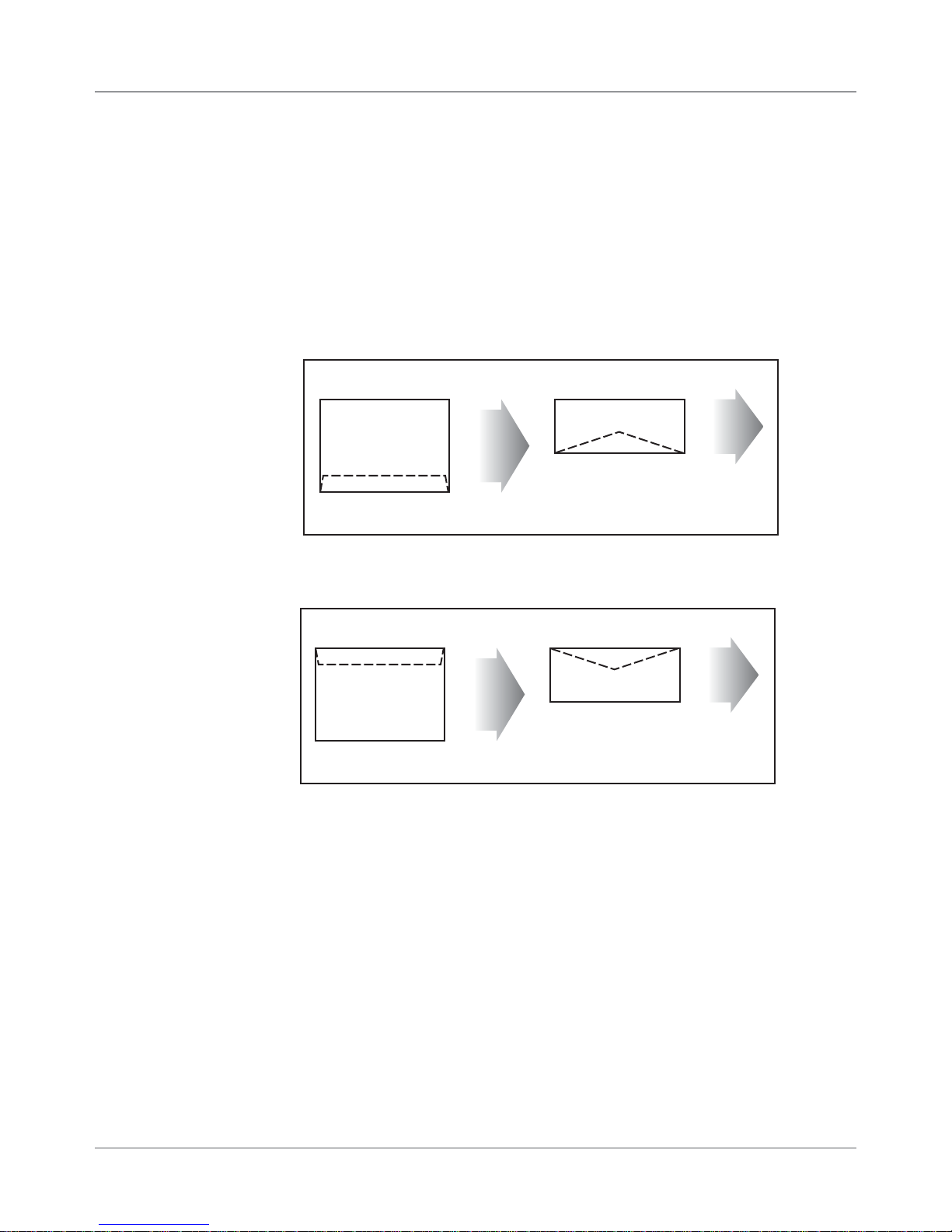
• All envelopes should be loaded so the side to be printed faces up, flap
faces down, stacked to feed with the left or right edge first. See example
that follows.
Example of Normal Orientation
This Side Prints
This Side Prints
Flap down, close to operator
Feed Edge
feeds into
printer.
Flap down, close to operator
• If running an inverted job (image prints upside down on media) your envelopes will load like the example below.
Feed Edge
feeds into
printer.
Example of Inverted Orientation
Feed Edge
feeds into
printer.
This Side Prints
Flap down, and away
from operator
Feed Edge
feeds into
printer.
This Side Prints
Flap down, and away
from operator
• All edges are viewed from the front surface of the material.
• Two clear zones, each 0.3" (7.6mm) wide, are required on the piece of
mail to allow clearance for the exit rollers.
• Printing is allowed to the top edge of the media, however print quality will
be degraded.
Print Heads
Able to produce spot color by swapping a black cartridge with a color cartridge on any head.
DA80F: 3 head capacity
DA95F: 6 head capacity
DA80F/DA95F AddressRight™ Printers Service Manual (SV61962 Rev. A)
2-5
2 • Specifications
2.4 Print
Specifications
Inkjet Cartridges
Cartridges are operator replaceable. The ink supply cartridges for the
DA80F and DA95F are the same ones used on their predecessor models
(see table on page 1-1). The table below lists some common order numbers for replacement cartridges. For a complete list of ink cartridges, go to
http://www.pb.com/supplies. In the Find Your Supplies field on the left pan-
el, select “AddressRight” from the dropdown list provided. Follow the links for
the model of your printer from the web page that displays.
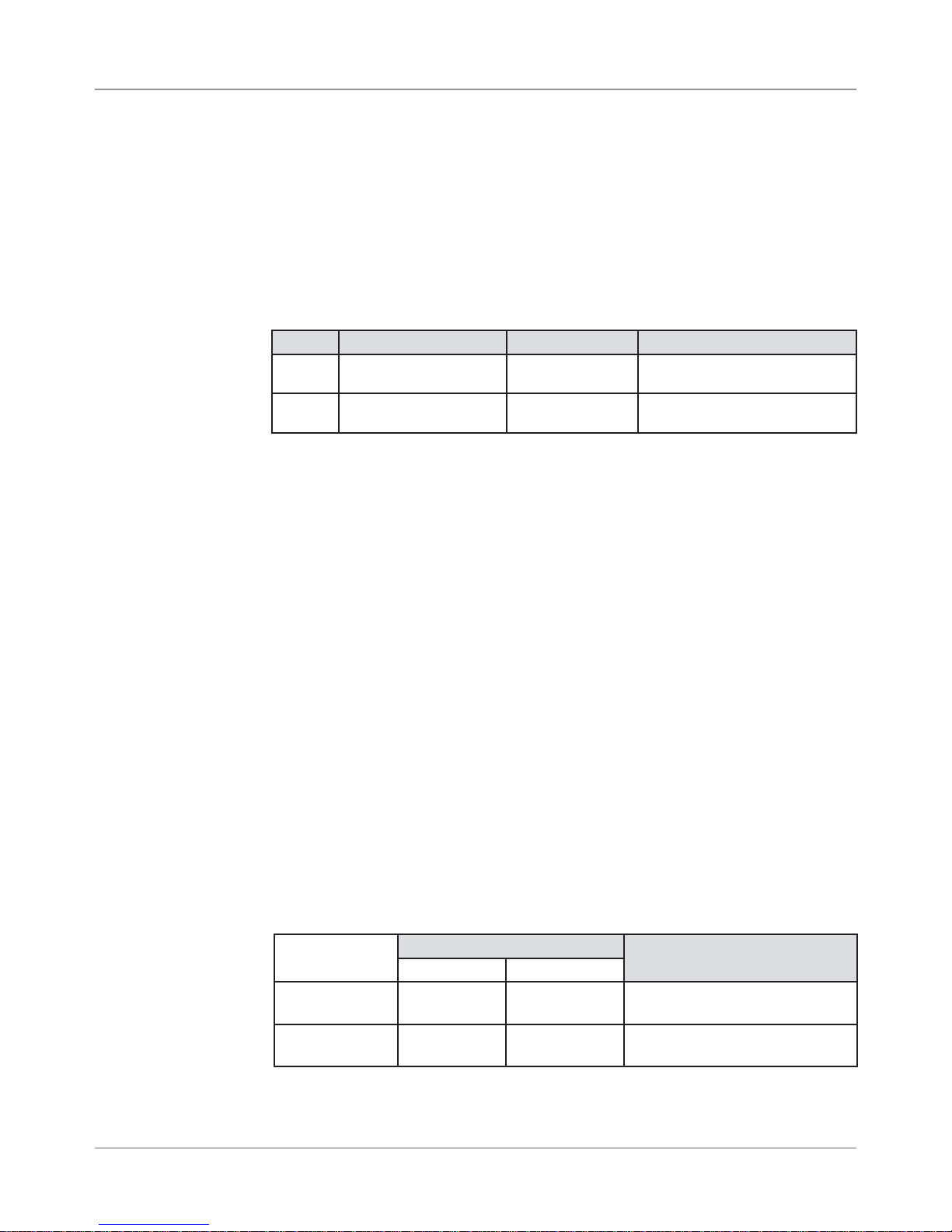
Model Printing Capability Black Cartridge Color Cartridge
DA80F Black and Spot Color
DA95F Black and Spot Color
HP Versatile Black
C8842A
HP Versatile Black
C8842A
HP 45 Spot Color Cartridges
Approved
HP 45 Spot Color Cartridges
Approved
Useful Life
User replaceable black and color ink jet cartridges. A cartridge printing 3 line
addresses with "light" mode off will provide approximately 30,000 pieces in
executive mode, 60,000 letter, 90,000 draft and 120,000 super draft, depending printer settings, materials and image density.
Print Position Accuracy
For a #10 or DL envelope (Acclaim #10 WW Commercial, Regular):
• Horizontal: within +/- 1.5 mm
• Vertical: within +/- 1.5 mm
• Skew: within +/- 1 degree
For other media:
• Horizontal: within +/- 3.0 mm
• Vertical: within +/- 3.0 mm
• Skew: within +/- 2-1/2 degrees
Recommended Usage
The printers have been tested under many different conditions. Use of the
printer should fall within these piece usage recommendations:
Monthly Piece Usage Product Life
Typical Maximum
DA80F 176,000 240,000 5 years or 14,400,000 cycles
(whichever comes first)
DA95F 480,000 1,000,000 5 years or 60,000,000 cycles
(whichever comes first)
NOTE: Usage beyond the maximum monthly pieces is not covered by the
Equipment Maintenance Agreement (EMA).
2-6 DA80F/DA95F AddressRight™ Printers Service Manual (SV61962 Rev. A)
Specifications • 2
2.4 Print
Specifications
✍
TIP: Any network
the print data has to
flow through to reach
the printer may affect (reduce) printer
throughput.
2.5 Material
Specifications
Throughput
DA80F: 22,000 envelopes hour
DA95F: 30,000 envelope per hour
Based on:
• "Super Draft" mode print quality
• 3-line destination address
• 18 characters per line
• 12-point character size
• Time New Roman font
NOTE: Adding graphics and/or printing at a higher resolution (e.g., Draft, Let-
ter, Executive mode) will decrease throughput.
For envelope addressing purposes, the printer is compatible with any word
processor or database application that can print a mailing label.
The paper types listed below are approved for use with the printer. Please note
that the dimensional limits above apply in all cases, and that all media (enve-
lopes, postcards, flats, etc.) should be without windows.
• White Wove
• Bond paper
• Recycled paper
• Coated paper
• Card stock
• Brown kraft
• Manila
• Perforations
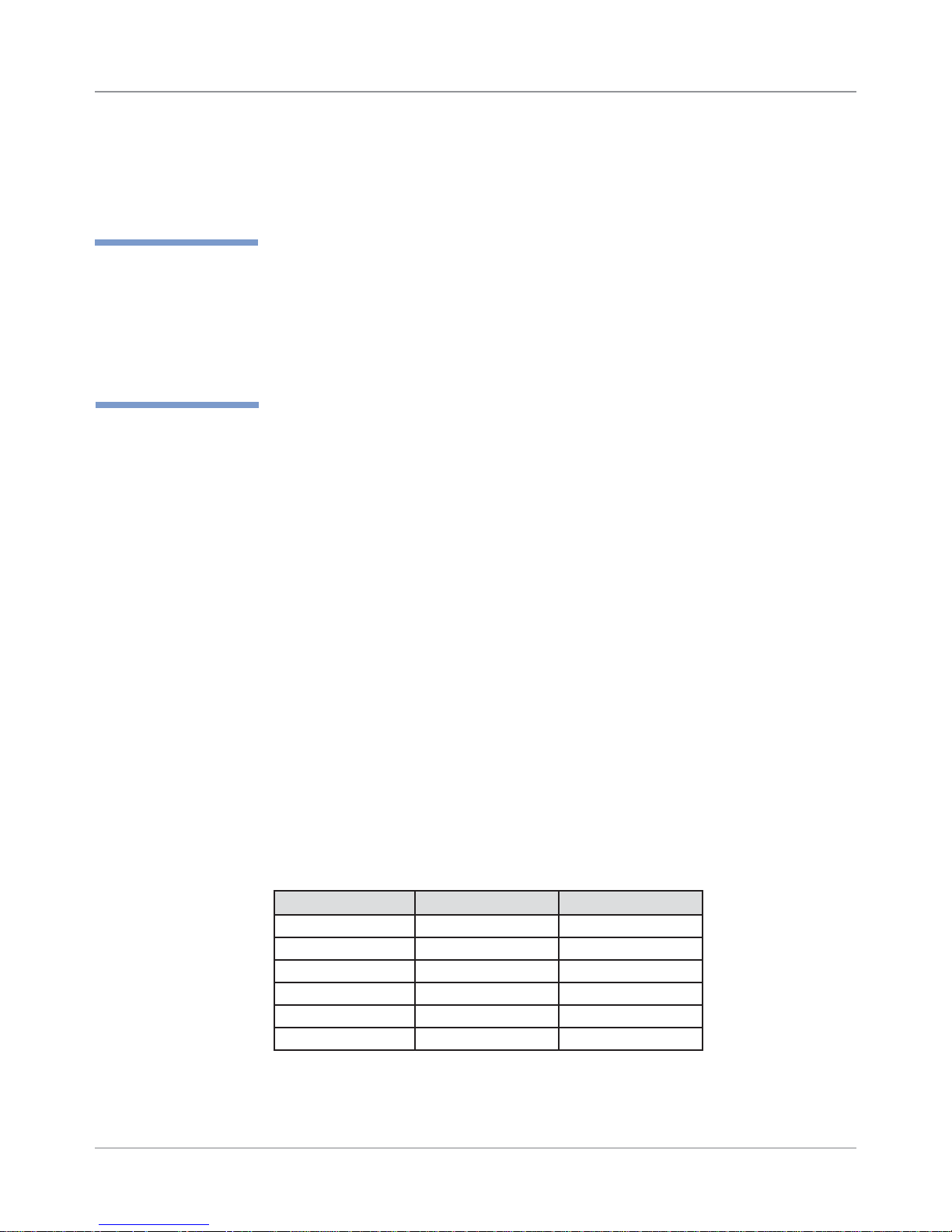
Refer to the table below for media size specifications.
Media Sizes
DA80F DA95F
Min. width 5" (127 mm) 5" (127 mm)
Max. width 14" (355 mm) 14" (355 mm)
Min. height (length) 3.5" (89 mm) 3.5" (89 mm)
Max. height (length) 15.5" (393 mm) 15.5" (393 mm)
Min. thickness 0.003" (0.08 mm) 0.003" (0.08 mm)
Max. thickness 0.25" (6.3 mm) 0.50" (12.7 mm)
Input Feeder Capacity
DA80F/DA95F: 500 #10 or DL Envelopes
DA80F/DA95F AddressRight™ Printers Service Manual (SV61962 Rev. A)
2-7

2 • Specifications
2.5 Material
Specifications
Approved Media
• Envelopes normally have a flap along the long edge and are processed
by the printer non-flap edge first (see illustration)
Non-flap
Lead Edge
Flap Edge
(flap faces down)
Envelopes may have either a diagonal or straight edge along the enve-
lope flap. Envelopes may have either a diagonal or straight edge along
the envelope flap. Stuffing materials must be machine folded (C, Z, or 1/2
folded) or cut sheets.
• Booklets are defined as media having physical dimensions 6" x 9”
(152mm x 229mm) or larger. Booklets have an opening along their long
edge which is covered by a flap with an adhesive seal.
• Catalog Envelopes have an opening along their short edge which is
closed by a flap with an adhesive seal. A catalog may consist of multiple
pages bound by adhesive or tabs on the feed edge or at 90 degrees with
respect to the feed edge. Material that is too stiff will cause feed problems.
• Postcards have no folds or bends. The printable side may have a higher
surface roughness than the non-printable side.
• Self-mailers may be of “C,” “Z,” or half-folded construction. They may not
exceed the maximum allowable thickness as specified on the previous
page and must be tabbed per postal regulations. Half-folds and tri-folds
must be machine produced.
• A catalog may consist of multiple pages bound by adhesive or tabs on
the feed edge or at 90 degrees with respect to the feed edge.
2
• Sheet stock may consist of 20 to 28 lb. (75 to 105g/m
) bond as well as
60 to 80 lb. (220 to 300g/m2) coated stock. The size and thickness constraints specified above apply.
2-8 DA80F/DA95F AddressRight™ Printers Service Manual (SV61962 Rev. A)
Specifications • 2
2.5 Material
Specifications
Unapproved Material
• Contaminants – material with visible material loss (loose powder, ink, sur-
face glaze, etc.) when hung free over a clean surface and struck sharply
with a standard wood ruler.
• NCR paper
• Special Materials – materials that are sensitive to heat such as thermal
papers, any pressure-sensitive materials, and materials that are sensitive
to minor magnetic fields.
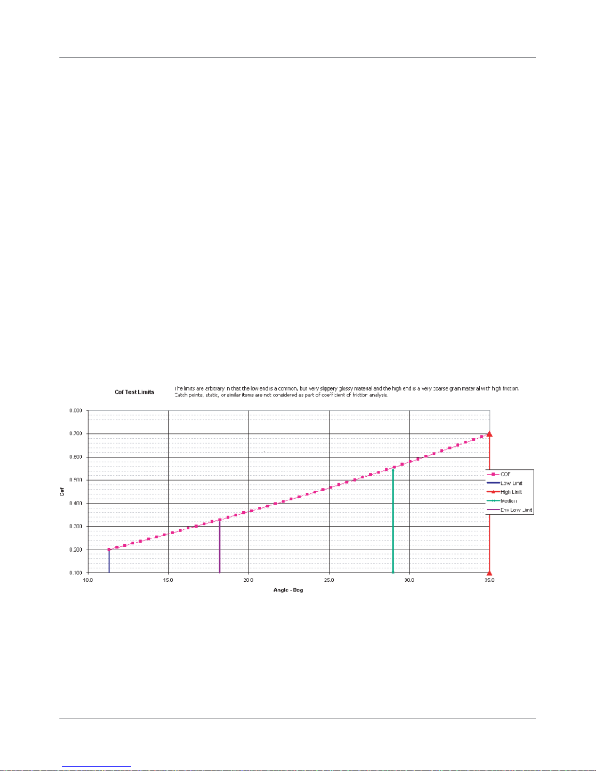
• Excessively Glossy Paper – this is material whose surface frictions falls
outside the guidelines given here (and in chart below).
- Material shall not slide when placed on a 18% slope (10.2 degrees).
- Envelopes shall not slide when placed on a 33% slope (18.2 degrees).
- Material shall slide when placed on a 70% slope (35 degrees).
To test material for proper surface friction (a clipboard is ideal for this test):
1. Secure bottom piece to slope and place ten pieces on top of the bot-
tom piece. Material shall be tested with short edge leading.
2. Raise the clipboard until any portion of the stack begins to slide. The
height to length ratio of the clipboard is the % slope. .
DA80F/DA95F AddressRight™ Printers Service Manual (SV61962 Rev. A)
2-9
2 • Specifications
2.5 Material
Specifications
✍
*Chou #3 Yoko, Chou
#4 Tate, and Hagaki
sizes cannot be used
with DA80F/DA95F
because they do not
meet the minimum
envelope width of
127mm (5 inches)
when run through the
printer in their usual
orientation.
Common Envelope/Paper Sizes
Paper Name Displayed in List Size (Width) Size (Height)
US/Canada Envelope/Paper Sizes
ENV_9 Envelope #9 8⅞"3⅞"
ENV_10 Envelope #10 9½" 4⅛"
ENV_11 Envelope #11 10⅜" 4½"
ENV_12 Envelope #12 11" 4¾"
PPR_Booklet_9_12 Booklet 9 x 12 12" 9"
ENV_MONARCH Envelope Monarch 7½" 3⅞"
PPR_Card_4_6 Card 6 x 4 6" 4"
PPR_Card_5_7 Card 7 x 5 7" 5"
LETTER Letter 8½" 11"
LEGAL Legal 8½" 14"
EXECUTIVE Executive 7¼" 10½ in
European Envelope/Paper Sizes
ENV_B4 Envelope B4 353mm 250mm
ENV_B5 Envelope B5 250mm 176mm
ENV_B6 Envelope B6 176mm 125mm
ENV_C4 Envelope C4 324mm 229mm
ENV_C5 Envelope C5 229mm 162mm
ENV_C6 Envelope C6 162mm 114mm
ENV_C65 Envelope C65 229mm 114mm
PG_ENV_C76 Envelope C76 162mm 81mm
PG_ENV_C7 Envelope C7 114mm 81mm
ENV_DL Envelope DL 220mm 110mm
ENV_DLX Envelope DLX 235mm 120mm
ENV_DLE Envelope DLE 225mm 114mm
A4 A4 210mm 297mm
A5 A5 148mm 210mm
Asian Envelope/Paper Sizes
Envelope 12JE 140mm 265mm
Envelope 9JE 190mm 265mm
Envelope 6JE 215mm 305mm
Envelope ZL [China] 230mm 120mm
Chou #3 Yoko* 120mm 235mm
Chou #4 Tate* 90mm 205mm
Hagaki* 100mm 148mm
Postcard #3 165mm 102mm
Postcard #4 183mm 100mm
Maximum Paper Size 14" (356mm) 15.5" (394mm)
2-10 DA80F/DA95F AddressRight™ Printers Service Manual (SV61962 Rev. A)

3 • Theory
3.1 Changes
From Earlier
Models
The DA80F (three print heads) and DA95F (six print heads) are fixed head,
ink jet desktop printers. The DA80F (WF81) and DA95F (WF96) printers are
based on the previous Pitney Bowes fixed head printers (DA400 and DA950,
respectively). For those familiar with the older models, the changes implemented include:
• Updated Main Board, as well as LCD/Keyboard Board/Print Head Driver
Board. Same Main Board used in both DA80F/DA95F models. Now
100% RoHS compliant.
• Elimination of Centronics (parallel) connector; replaced by Ethernet connector (USB port kept)
• Improved paper sensor calibration now accessible via LCD Service menu
• New options on the LCD control panel menus for greater flexibility and
control
• Introduction of a Pitney Bowes “software control panel” (running under
Windows on a separate PC) which mimics the features of the printer’s LCD
control panel while also adding more diagnostic and administrative features
• Control panel menu supports bulk cartridge ink management (“low ink“
warning now works when using these types of cartridges)
• Removed large transformer and replaced with heavier duty power supply
(allows a graceful shutdown of the printer and for the software parameters
to be saved). Same supply as used in DA5xx/DA7xx shuttle-head printers.
• Print heads now raise up straight (instead of to the side) which allows
easier access to wipe and clean the print heads
• One printer software for all functionality (uses PB monolithic driver)
• Support for 18 languages in the Operator Guide, soft control panel, and
drivers
DA95F-Specific Improvements
• Removed feeder board (used in predecessor DA950 model)
• New exit sensor and new feeder deck extension
• New “feet” on bottom of feeder allows better alignment of feeder
• Two new idler roller assemblies provide better control of the media
through the print path resulting in better print quality and more accurate
placement of printed items
DA80F-Specific Improvements
• New feeder clutch added
• Added auto-tensioner on drive belts.
• Media thickness range increased from 1/8” to ¼”
DA80F/DA95F AddressRight™ Printers Service Manual (SV61962 Rev. A)
3-1

3 • Theory
3.2 Printer
Architecture
The printer system is made up of several sub-systems (see also Figure 3-1):
• Universal Power Supply - The universal power supply has auto sensing/
switching for input voltage and intelligent shutdown capability. It ensures
proper parking of the cartridges in the maintenance station and proper
shutdown of the software. (It is the same supply used in the midrange
DM series mailing machines.)
• System Controller - The system controller is comprised of the overall op-
erating system in the firmware that controls the behavior of the system
and coordinates activities between the other sections.
• User Interface - The user interface is the LCD display, the buttons, and
the software to drive it within the firmware.
• Feeder and Transport Motion Control - The feeder and transport motion
control is responsible for feeding and positioning the envelope beneath
the printer for printing. All material motion is controlled by the transport
motor and firmware.
• Head Management - The head management controls the proper operation
of the print cartridges.
• Communications - The communications hardware and firmware are re-
sponsible for the interface to the host PC through which print streams are
received and passed to the system controller for parsing and rendering.
Power
Universal Power
Supply
Communications
USB Ethernet
Busy/Error
System
Controller
Head
Management
Display
Te xt
User Interface
Motion Control
Operator
Input
Feeder
and
Transport
LED
3-2 DA80F/DA95F AddressRight™ Printers Service Manual (SV61962 Rev. A)
Figure 3-1 Printer System Functional Architecture
Theory • 3
3.2 Printer
Architecture
✍
TIP: Module A =
Print Heads 1, 2, 3
Module B =
Print Heads 4, 5, 6
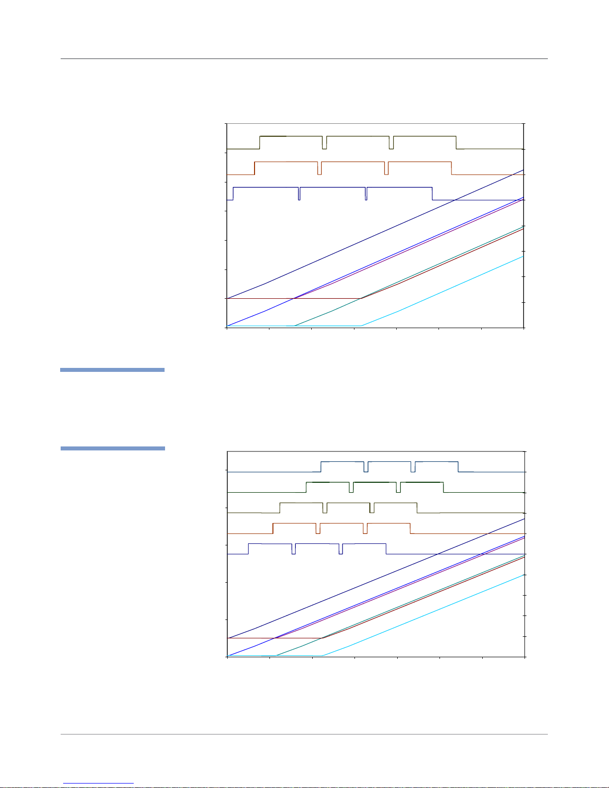
Throughput
Cycle Time
Values
Material #10 Envelope
Model
22828
0.158
60.000
50.000
40.000
30.000
20.000
10.000
0.000
-10.000
0.0000 0.1000 0.2000 0.3000 0.4000 0.5000 0.6000 0.7000
WF81
Figure 3-2 DA80F (WF81) Printer Timing Diagram
Throughput 32230
Cycle Time 0.112
90.000
70.000
Print Sensor
50.000
Values
30.000
pcs/hr
sec
Module A Printing
Feeder Sensor
pcs/hr
sec
Exit Sensor
Module A Printing
Module B Printing
Print Sensor
Timing Diagram
Piece 1 Piece 3Piece 2
Time
Timing Diagram
Feeder Sensor
Piece 1 Piece 3
Piece 2
1.5
1
0.5
0
-0.5
-1
-1.5
-2
-2.5
2.5
2
1.5
1
0.5
0
-0.5
-1
10.000
-10.000
Material #10 Envelope
Model WF96
DA80F/DA95F AddressRight™ Printers Service Manual (SV61962 Rev. A)
-1.5
-2
-2.5
0.0000 0.1000 0.2000 0.3000 0.4000 0.5000 0.6000 0.7000
Time
Figure 3-3 DA95F (WF96) Printer Timing Diagram
3-3
3 • Theory
3.2 Printer
Architecture
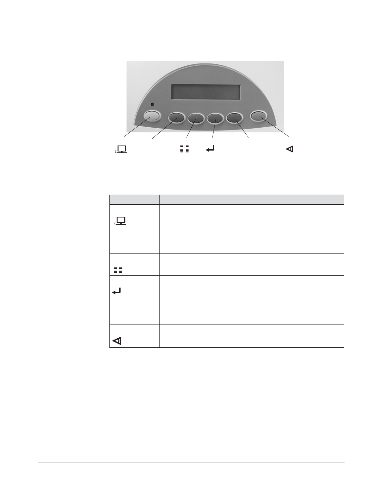
On Line
_
Menu Enter
+
Test Env.
Figure 3-4 User Interface ( Control Panel) on Printer
The buttons on the control panel perform the following functions:
Button Description
ON LINE
_
(minus)
Menu
Enter
(plus)
+
Test Env
• Toggles (switches) between ON LINE (communicates with host
PC) and OFF LINE (no communications with host PC).
• Exits the menu system.
• Decrements a value.
• Moves backwards through a choice list.
• Negative response to query.
• Enters the menu system when OFF LINE.
• Exits a submenu.
• Selects and/or saves the displayed value.
• Causes system to perform described action.
• Advances to next screen.
• Increments a value.
• Moves forward through a choice list.
• Affirmative response to a query.
• Prints a test piece when OFF LINE.
• Prints a report for specific menu items.
NOTE: See Appendix A, Printer Control Panel Menus for a full explanation of
all the menu options.
3-4 DA80F/DA95F AddressRight™ Printers Service Manual (SV61962 Rev. A)

Theory • 3
3.3 Operating
Sequence
When the printer is either, “off line” (led is unlit) and the [test] button is depressed, or the printer is “on line” (led is lit) and a valid address is received
from the computer, the belt drive motor will be energized. A belt, driven by
the motor, drives the belt drive roller assembly which in turn drives the media
belts.
The printer motor will be energized. The printer belt connects the printer motor to the transport roller and exit roller. The processor board will compare
the speed of the encoder on the transport roller to calculate the desired
speed.
The feed motor will be energized, and the feed rollers and feed belt will rotate, pushing the bottom piece of media between the rollers and the “h” block
media separators. The frictional design of the “h” block media separator is to
restrict all but the bottom piece of media.
The feed roller moves the piece of media between the entry idler rollers and
the transport rollers. The speed differential between the transport rollers and
the feed rollers will create a gap between the moving pieces. The feeder
photo sensor assembly is energized as the piece of media is pushed out.
The transport roller continues to push the leading edge of the media into the
path of the printer sensor. When the leading edge of the media is detected
by the printer sensor assembly, two things occur:
• Position counting begins so that printing will occur at the preprogrammed
position on the media. This pre-programmed position is set in the address layout or is controlled by the software driver.
• The media is captured between the exit roller and the exit idler roller
where it is ejected from the printer. In the DA95F, an exit sensor captures
the piece exit data.
This process is repeated until all the records in the file are printed.
DA80F/DA95F AddressRight™ Printers Service Manual (SV61962 Rev. A)
3-5

3 • Theory
3-6 DA80F/DA95F AddressRight™ Printers Service Manual (SV61962 Rev. A)

4 • Troubleshooting/Diagnostics
4.1
Troubleshooting
Overview
✍
TIP: See Appendix B
- Printer Communications, for troubleshoot-
ing problems relating to
networking and printer
communications.
This chapter discusses printer troubleshooting in the following sections:
4.2 Block Diagrams ........................................................................ 4-2
4.3 Main Controller Board Diagnostics ........................................... 4-4
4.4 Error Codes ............................................................................... 4-9
4.5 Print Samples for Troubleshooting .......................................... 4-12
4.6 Feeding Issues ........................................................................ 4-14
4.7 Printing Issues ......................................................................... 4-19
4.8 Display Issues ......................................................................... 4-23
4.9 Miscellaneous Issues .............................................................. 4-23
When You Start Y our Troubleshooting
When any paper handling/printing errors begin to occur frequently, perform
the following standard printer setup procedures in the order given. There is
a high likelihood that performing these procedures will correct the error. If
these procedures do not correct the problem, then refer to the troubleshoot-
ing tables starting on page 4-14 for further actions, including part removal/
replacement.
Standard Printer Setup Procedures
(see DA80F or DA95F Operator Guides for specific instructions)
1. Verify that the output stack is not backing up into paper path
2. Recheck standard feeder setup procedures:
a. Adjust the “H” blocks
b. Adjust input ramp
c. Adjust feed guide
d. Verify stack weight limits
e. Adjust side guides
f. Check feed roller/belt surface for glazing
3. Check the thickness adjustment on the print heads
4. Check all adjustable nips for position and tension
5. Clean the paper path
6. Sensors:
a. Clean Sensors
b. Calibrate Sensors
c. Check Sensor Operation
DA80F/DA95F AddressRight™ Printers Service Manual (SV61962 Rev. A)
4-1
4 • Troubleshooting/Diagnostics
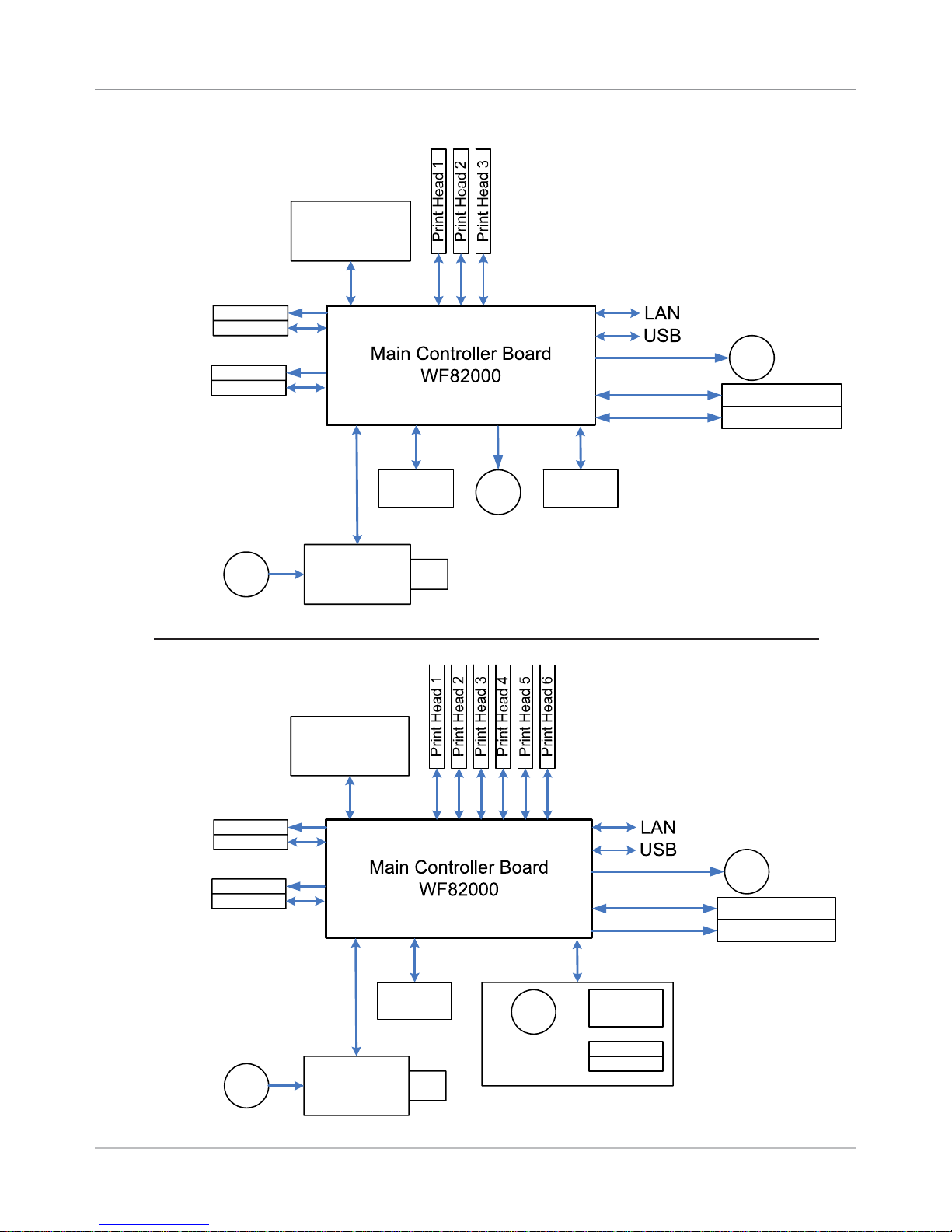
4.2 Block
Diagrams
Control Panel &
Display Board
WS82002
Paper Sensor
Emitter
Receiver
Feeder Sensor
Emitter
Receiver
Universal
AC Fan
Power Input
Power Supply
WS80001
Shaft
Encoder
M
Feeder Motor
Figure 4-1 DA80F (WF81)
Printer Block Diagram
Transport Motor
M
PB Stacker
Bryce Stacker
Feeder
Encoder
Control Panel &
Display Board
WS82002
Paper Sensor
Emitter
Receiver
Exit Sensor
Emitter
Receiver
Universal
AC Fan
Power Input
Power Supply
WS80001
Shaft
Encoder
M
Feeder Motor
External Feeder
Figure 4-2 DA95F (WF96)
Printer Block Diagram
Transport Motor
M
PB Stacker
Hi Speed Feeder
Feeder
Encoder
Emitter
Receiver
Feeder Sensor
4-2 DA80F/DA95F AddressRight™ Printers Service Manual (SV61962 Rev. A)
3RZHU
6ZLWFK
,(&
FRQQHFWRU
8VHU,QWHUIDFH
/&'%XWWRQV
IURP.0DFKLQH
)(0$%DFNOLJKW/&'
)HHGHU
0RWRU
'&%UXVK
:6
9'&
([LW6HQVRU .
:65HFHLYHU237(.23
+%ULGJH
'ULYHU
6,
&38 6+
5HQHVDV6+
+'%3$'9
99
6'5$0
07/&0
0%0LFURQ
9
)/$6+
()-&
0%,QWHO
9
0LG-HW
3RZHU
VXSSO\
)XVH
;LOLQ[)3*$
6SDUWDQ(6HULHV
;&6()7*&
999
..6<67(0
%/2&.',$*5$0
..
0DLQ%RDUG
7UDQVSRUW
0RWRU
'&%UXVK
:6
9'&
+%ULGJH
'ULYHU
6,
5HJXODWLRQIRU
999
999
9
86%)XQFWLRQ
3KLOLSV
,63$
(WKHUQHW
606&
/$1&
IRUWHVWRQO\
5(6(7
&LUFXLWU\
56
'ULYHU
</HH
(QFRGHUDWVKDIW+3
+('6$&35.
+('0%&35.
9$
9$
',3
6ZLWFK
-
ELW
'$7$
ELW
'$7$
)5$0
0+]
-7$*
-7$*
0+]0+]
ELW'DWDELW'DWD
&RQILJ3LQIRU..
WKUX3DSHUVHQVRUUHFHLYHU
5HG/('
*UHHQ/('
-
--
-.
/$1
86%
)$1
'(
-
-5$7\SH%
-5$0DJQHWLFV/('
([LW6HQVRU .
:6(PLWWHU237(.23%
&RQILJ3LQIRU6:9HUFRQWURO
,54
,5/
(QFRGHUDWPRWRU
+3+('6)
&35
)HHGHU6HQVRU .
:6(PLWWHU237(.23%
)HHGHU6HQVRU .
:65HFHLYHU237(.23
3DSHU6HQVRU ..
:65HFHLYHU237(.23
3DSHU6HQVRU..
:6(PLWWHU237(.23%
-
- - - -
3+ 3+ 3+ 3+ 3+ 3+
)HHGHU
'ULYHU
.
6WDFNHU
'ULYHU
.
+L6SHHG
)HHGHU
'ULYHU
.
)HHGHU
0RWRU
(QFRGHU
6HQVRU
3%6WDFNHU,)
-
%U\FH
6WDFNHU,)
,&WR'$
0$;
5HFHLYHU
&LUFXLWU\
3LQ3LQ
-.
-.
-.
- -
-
-
-
-
:).
:).
-
-
-
.RQO\
.RQO\
.RQO\
3RZHU6XSSO\
$VVHPEO\
-
-
-
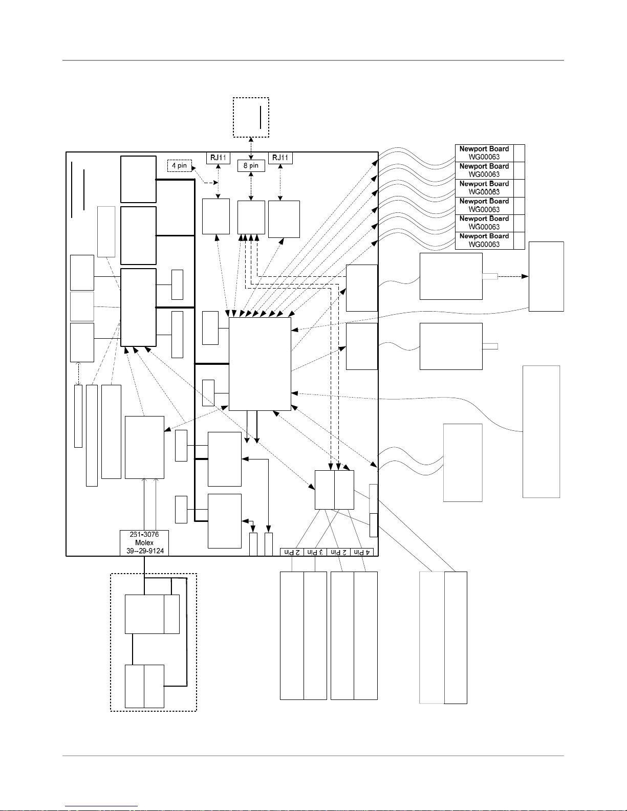
4.2 Block
Diagrams
Troubleshooting/Diagnostics • 4
Figure 4-3 DA80F (WF81)/DA95F (WF96) Printer Detailed Block Diagram
DA80F/DA95F AddressRight™ Printers Service Manual (SV61962 Rev. A)
4-3
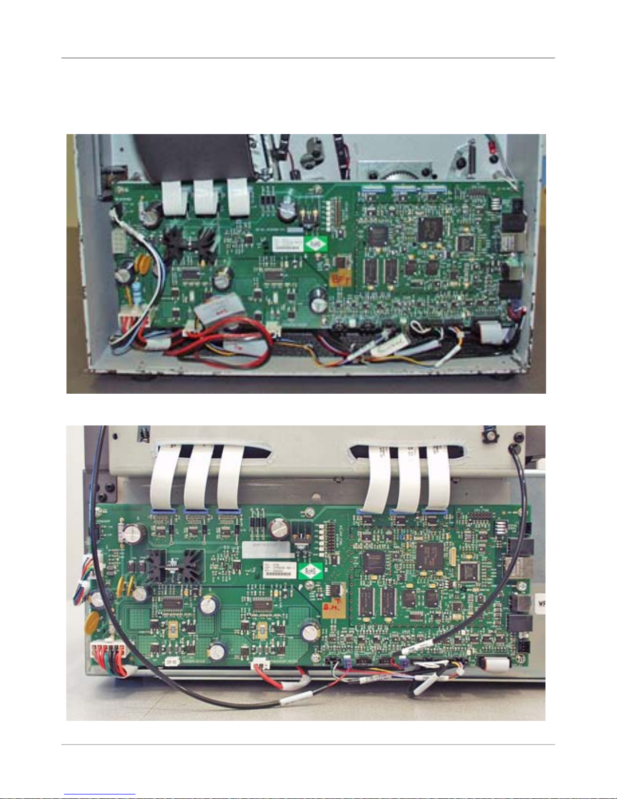
4 • Troubleshooting/Diagnostics
4.3 Main Controller
Board Diagnostics
Figure 4-3 Main Controller Board Mounted in DA80F (WF81) Printer
Figure 4-4 Main Controller Board Mounted in DA95F (WF96) Printer
4-4 DA80F/DA95F AddressRight™ Printers Service Manual (SV61962 Rev. A)
 Loading...