

Page 1
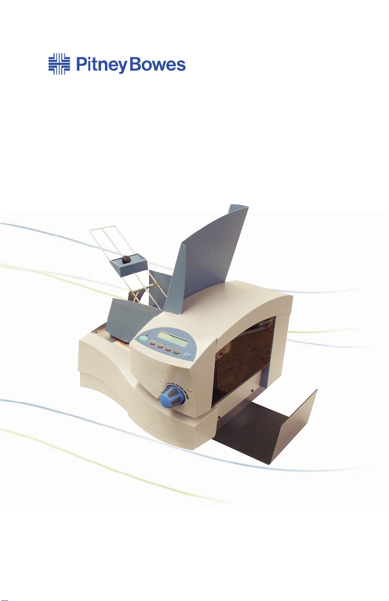
AddressRight™DA Series Printer
DA70S, DA75S
Operator Guide
US/International English Version
Page 2

NOTICE
The use of this information by the recipient or others for purposes
other than the repair, adjustment or operation of Pitney Bowes
equipment may constitute an infringement of patent and/or other
intellectual property rights of Pitney Bowes or others. Pitney Bowes
assumes no responsibility for any such use of the information.
Except as provided in writing, duly signed by an officer of Pitney
Bowes, no license, either express or implied, under any Pitney
Bowes or any third party’s patent, copyright, or other intellectual
property rights is granted by providing this information.
SV61665 Rev. D
Fourth Edition, December, 2006.
©2006 Pitney Bowes Inc. All rights reserved.
This book may not be reproduced in whole or in part in any fashion
or stored in a retrieval system of any type or transmitted by any
means, electronically or mechanically, without the express written
permission of Pitney Bowes.
We have made every reasonable effort to assure the accuracy and
usefulness of this manual, however we can not assume responsibility
for errors or omissions or liability for the misuse or misapplication of
our products.
Envelope Designer and SmartMailer are registered trademarks
of Pitney Bowes, Inc. Microsoft and Windows are trademarks or
registered trademarks of Microsoft Corporation.
NOTE: DA70S/DA75S
The similarity of the DA70S and DA75S printers allows their features
and operation to be documented together. The principle difference
in these printers is that the DA75S is a color printer that uses both
a black and color ink cartridge. The DA70S only uses a black ink
cartridge.
The photos and illustrations in this document are of the DA75S
printer, but representative of each printer.
IMPORTANT: Model and feature availability varies by country.
Contact your machine supplier for more information. This guide
covers all models and features. Inclusion within this guide does not
guarantee availability of a particular model or feature within your
country.
Page 3

Conforms to the Following:
FCC Rules
NOTE: This equipment has been tested and found to comply with
the limits for a Class A digital device, pursuant to part 15 of the FCC
Rules. These limits are designed to provide reasonable protection
against interference when the equipment is operated in a commercial
environment. This equipment generates, uses, and can radiate
radio frequency energy and, if not installed and used in accordance
with the instruction manual, may cause interference to radio
communications. Operation of this equipment in a residential area is
likely to cause interference in which case the user will be required to
correct the interference at his own expense.
CAUTION: Changes or modifications to this equipment not
expressly approved by the party responsible for compliance could
void the user’s authority to operate the equipment.
Shielded USB cables must be used with this equipment to ensure
compliance with the limits. Use of unshielded USB cables is
prohibited.
WARNING! This is a Class A product. In a domestic environment
this product may cause radio interference in which case the user
may be required to take adequate measures.
EMC Directive 89/336/EEC
Low Voltage Directive 73/23/EEC
Tested for compliance by TUV Rheinland Product Safety
to meet regulatory requirements in USA, Canada, and Europe.
Also Conforms to:
Directive 2002/96/EC (OJ:L37/24/2003) on waste electrical and
electronic equipment (The WEEE Directive)
Directive 2002/95/EC of the European Parliament and of the Council
of 27 January 2003 on the restriction of the use of certain hazardous
substances in electrical and electronic equipment.
Page 4

Table of Contents
Contact Information List
USA Contacts .......................................................................iii
Canada Contacts ..................................................................iii
Other Country Contacts .......................................................iv
Chapter 1 - Introduction
Welcome to the DA70S/DA75S Ink Jet Printer ..................1-2
Using This Guide ...............................................................1-2
System Requirements .......................................................1-2
Getting Help .......................................................................1-3
Online Help ................................................................ 1-3
Printer Options ...................................................................1-3
Important Safety Notes ......................................................1-4
Other Informational Cautions ..................................... 1-5
Important Safety Notes for the EU Only ..................... 1-6
Printer Parts and Locations ...............................................1-7
Chapter 2 - Printer Basics
Printer Features Overview .................................................2-2
Setting Up a Job ................................................................2-3
1. Setting the Separator Gap ................................... 2-3
2. Centering the Input Guide under the Material .....2-5
3. Setting the Feed Angle ........................................ 2-6
4. Setting the Feed Ramp ........................................ 2-8
5. Position the Side Guide ....................................... 2-9
6. Loading Material ................................................ 2-10
7. Adjusting the Media Thickness Knob .................2-11
8. Adjusting the Exit Rollers ................................... 2-12
9. Printing a Test Piece .......................................... 2-13
Printer Driver Software ....................................................2-13
Selecting Printer Properties ..................................... 2-13
Using the Control Panel ...................................................2-14
Using the Menus ..............................................................2-15
Using the Main Menu ............................................... 2-16
Using the Setup Menu ............................................. 2-17
iSV61665 Rev. D
Page 5

Table of Contents
Chapter 3 - Printer Maintenance
Preventive Maintenance ....................................................3-2
Print Quality Problems .......................................................3-2
Cleaning the Exit Rollers ...................................................3-3
Cleaning the Sensor ..........................................................3-3
Cleaning the Printhead Shaft .............................................3-3
Cleaning the Floor Assembly and Top Cover ....................3-4
Purging the Printhead ........................................................3-4
Installing and Removing the Ink Jet Cartridges .................3-5
Installing the Ink Jet Cartridges (Color & Black) ........ 3-5
Removing the Ink Jet Cartridges ................................ 3-6
CMYK Printing Alignment (DA75S ONLY) .........................3-8
Chapter 4 - Troubleshooting
Problems and Solutions .....................................................4-2
Feed Problems ..................................................................4-2
Print Quality Problems .......................................................4-3
Interface Problems ............................................................4-4
Motor Problems .................................................................4-4
Barcode Problems .............................................................4-5
Other Problems .................................................................4-6
Appendix A - Specifications
Equipment Specifications ................................................. A-2
Material Specifications ...................................................... A-9
Appendix B - Glossary
Glossary ........................................................................... B-1
Index
Index ...................................................................................I-1
ii SV61665 Rev. D
Page 6

Contact Information List
USA Contacts
Product Name - DA70S or DA75S
▪ For frequently asked questions, go to: www.pb.com and click on
Customer Support.
▪ To place requests for service or training, go to: www.pb.com and
click on My Account.
▪ To order supplies and accessories, call the Supply Line™ at:
1.800.243.7824 or go to: www.pb.com and click on Online
Store.
▪ To view and pay invoices online, go to: www.pb.com and click
on My Account.
▪ To view inventory, go to: www.pb.com and click on My Account.
▪ For direct questions, call: 1.800.522.0020. Customer Service
Representatives are available Monday through Friday, 8:00 AM
- 8:00 PM ET.
Canada Contacts
Product Name - DA70S or DA75S
▪ For frequently asked questions or to order supplies, go to:
www.pitneybowes.ca
▪ For direct questions, call: 1.800.672.6937. Customer Service
Representatives are available Monday through Friday, 8:30 AM
- 4:00 PM ET.
iiiSV61665 Rev. D
Page 7

Contact Information List
Other Country Contacts
Contact information is given in a separate publication supplied with
the product.
iv SV61665 Rev. D
Page 8

1 • Introduction
The DA70S/DA75S printer is a versatile, easy-to-use desktop
printer designed for addressing applications. This chapter
explains what's in this guide, and tells you how to order
supplies and where to get more information about using your
printer.
Welcome to the DA70S/DA75S Ink Jet Printer ...................1-2
Using This Guide ................................................................1-2
System Requirements ........................................................1-3
Getting Help........................................................................1-3
Online Help ..................................................................1-3
Printer Options....................................................................1-4
Ordering Supplies ...............................................................1-4
Important Safety Notes .......................................................1-5
Printer Parts and Locations ................................................1-6
1-1SV61665 Rev. D
Page 9

1 • Introduction
Welcome to the DA70S/DA75S Ink Jet Printer
The DA70S/DA75S ink jet printer is a desktop printer used to print
addresses, graphics and other information, in color (DA75S only),
on a wide range of material of various sizes, construction and
composition. You can define the font, placement, print quality and
barcode characteristics for your addresses.
Using This Guide
Refer to this guide for information about printer setup, operation and
troubleshooting. It is divided into the following chapters:
Chapter 1, Introduction - Contains an overview of the Operator
Guide, Help resources, safety information, as well as printer parts
and locations.
Chapter 2, Printer Basics - Explains how to set up your printer to
run a job.
Chapter 3, Printer Maintenance - Describes how to keep the printer
clean and functioning properly.
Chapter 4, Troubleshooting - Contains a list of possible problems
and their solutions.
Appendix A, Specifications - Provides hardware and material
specifications. Your printer will run at its best when your material
conforms to our specifications.
Appendix B, Glossary - Explains the meanings of common terms
used with address printing equipment.
System Requirements
In order to operate the printer with your computer, your system must
meet the following requirements:
CPU: Pentium III 500MHz. or greater, 500MB RAM or more
preferred
Operating System: Windows 2000/2003 Server/XP
USB Cable or Ethernet Cable: A USB cable is supplied with your
printer. If you choose to use another cable, make sure it isn't any
longer than 16 feet (5m).
1-2 SV61665 Rev. D
Page 10

Introduction • 1
Getting Help
As you use your printer, there may be times when you need help
to solve a specific application problem, or you may want additional
information about printer operation.
Refer to the Contact Information List at the front of this guide for
more information or in the separate contact sheet supplied with your
machine.
Online Help
The Print Driver for your printer has a built-in help system. To get to
the driver, click on Properties from Windows print dialog box. Rightclick on items in question for the "What's This" Help button.
If you're using programs such as Envelope Designer™ or
SmartMailer™, press the F1 key while you're using the program
to display information about the open screen. Select the Help
menu to display a list of topics or search for a term. Refer to the
documentation supplied with these programs for more information.
NOTE: The availability of software varies by country. Refer to your
machine supplier for details of software available to you.
Printer Options
There are several options available for your addressing printer, such
as ink drying equipment which may reduce smudging on glossy
stock, stackers, and envelope designing software.
NOTE: The availability of software and product varies by country.
Refer to your machine supplier for availability details in your
country.
1-3SV61665 Rev. D
Page 11

1 • Introduction
Important Safety Notes
Follow the normal safety precautions for all office equipment:
• It is recommended that you use only Pitney Bowes approved
supplies, in particular aerosol dusters. Improper storage and
use of aerosol dusters or flammable aerosol dusters, can cause
an explosive-like condition that could result in a personal injury
and/or property damage. Never use aerosol dusters labeled
flammable and always read instructions and safety precautions
on the duster container label.
• To obtain supplies, please contact our Supply Line™ to place
orders. Material Safety Data Sheets can be obtained on the web
or from our Supply Line™. Refer to the Contact Information List
for more information.
• Use the power cord supplied with the machine and plug it into
a properly grounded wall outlet located near the machine and
easily accessible. Failure to properly ground the machine can
result in severe personal injury and/or fire.
• Avoid touching moving parts or materials while the machine is in
use. Keep hands, loose clothing, jewelry and long hair away from
all moving parts.
• Do not remove covers or defeat safety interlock switches. Covers
enclose hazardous parts that should only be accessed by
properly trained service personnel. Immediately report to service
any damaged or non-functioning components that renders the
unit unsafe.
• Place the unit in an accessible location to allow for proper
venting of the equipment and to facilitate servicing.
• The power cord wall plug is the primary means of disconnecting
the machine from the AC supply.
• Do not use an adapter plug on the line cord or wall outlet.
• Do not remove the ground pin from the line cord.
• Avoid using wall outlets that are controlled by wall switches, or
shared with other equipment.
• Do not route the power cord over sharp edges or trap between
furniture.
1-4 SV61665 Rev. D
Page 12

Introduction • 1
• Ensure there is no strain on the power cord and that it does not
become jammed between the equipment, walls or furniture.
• Be certain the area in front of the wall receptacle into which the
machine is plugged is free from obstruction.
• Before clearing a jam, be sure machine mechanisms come to a
stop.
• When removing jammed material, avoid using too much force to
protect against minor personal injury and damaging equipment.
• To prevent overheating, do not cover the vent openings.
• Operation of this equipment without periodic maintenance will
inhibit optimum operating performance and could cause the
equipment to malfunction. Contact your machine supplier for
required service schedule.
• Read all instructions before attempting to operate the equipment.
• Use this equipment only for its intended purpose.
Other Informational Cautions
NOTES:
• In case of an ink spill, leaking ink, or excessive ink
accumulation, immediately disconnect the power cord plug
from the wall outlet and call your machine supplier for a
cleaning.
• Always follow the specific occupational safety and health
standards for your workplace.
• Avoid using wall outlets that are controlled by wall switches,
or shared with other equipment. If a wall outlet controlled by
a wall switch is used, mail could be interrupted if the printer is
plugged in when the wall switch is used to turn power off.
1-5SV61665 Rev. D
Page 13
1 • Introduction
Important Safety Notes for the EU Only
In some countries the equipment is supplied with a moulded mains
lead and plug. In other countries, or if the supplied lead is not used,
the following information applies:
1. An approved mains lead for the country concerned must be
used.
2. As the colours of the wires in the mains lead of this equipment
may not correspond with the coloured markings identifying the
terminals in your plug, proceed as follows:
- The wire which is coloured green and yellow must be
connected to the terminal in the plug which is marked with
the letter “E” or by the earth symbol (
or green and yellow.
- The wire which is coloured blue must be connected to the
terminal which is marked with the letter “N” or coloured
black.
- The wire which is coloured brown must be connected to the
terminal which is marked with the letter “L” or coloured red.
3. The wires in the supplied mains lead are coloured in accordance
with the following code:
Green and Yellow - Earth
Blue - Neutral
Brown - Live
) or coloured green
WARNING! THIS EQUIPMENT MUST BE
EARTHED. The socket outlet should be near to the
equipment and should be easily accessible.
1-6 SV61665 Rev. D
Page 14

Introduction • 1
Printer Parts and Locations
The figure below calls out key machine components, each of which
is briefly described in the text that follows. Refer to the figure below
for component location.
2
1
3
6
4
5
7
8
11
10
9
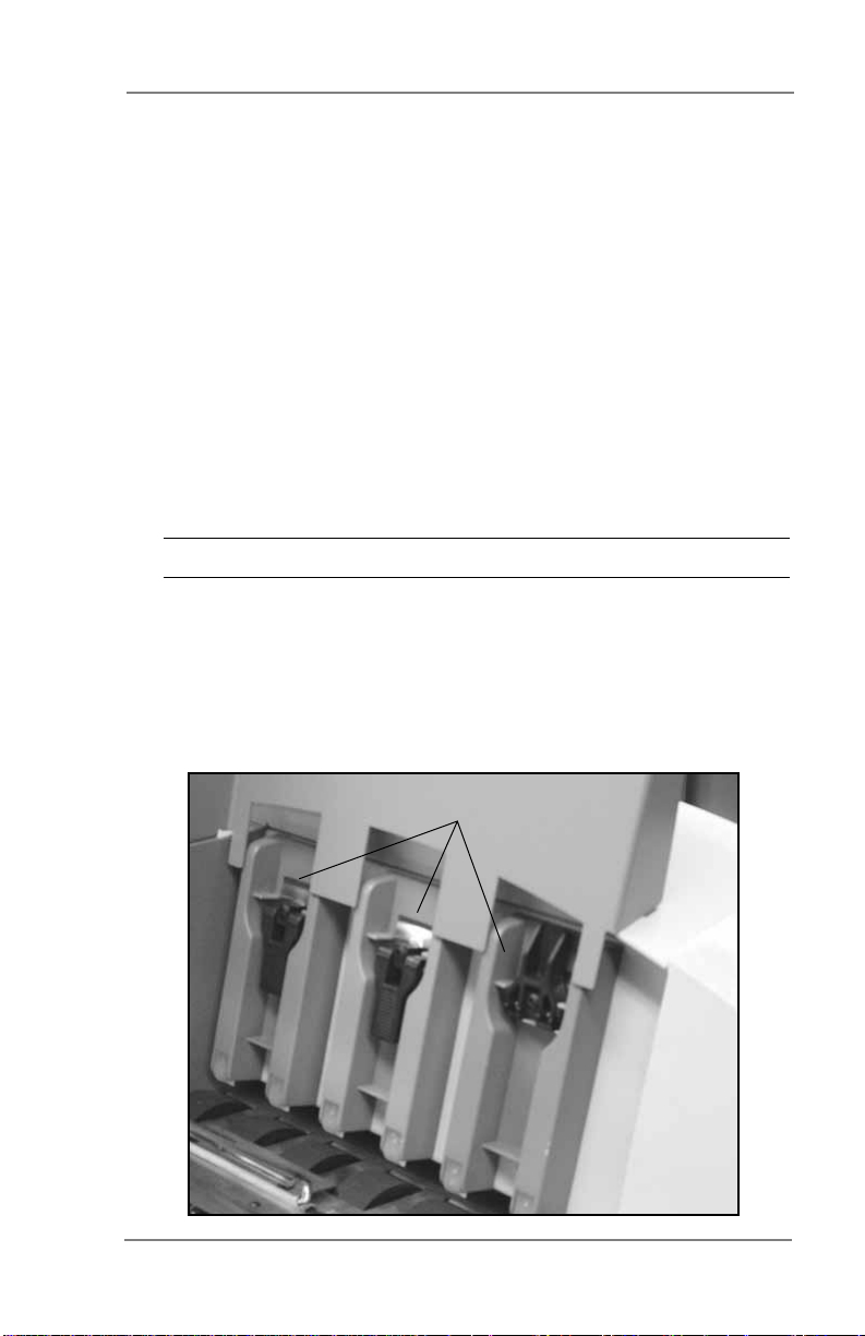
H-Block Separators - Adjust to the thickness of your
1
material. The gap between the H-Block separator fingers
and the feed rollers should be just enough to allow a single
piece to feed through the printer.
1-7SV61665 Rev. D
Page 15

1 • Introduction
Feed Ramp and Lock Knob - The feed ramp adds a gentle
2
slope to the stack to help feeding. Lower the ramp until the
top of the bottom piece in the stack reaches the middle of
the ramp. Secure the ramp with the lock knob.
Input Guide - Supports the material stack.
3
Input Guide Slide and Lock Knob - Move the slide up and
4
down to adjust the feed angle to accommodate the weight
of the material you're running. Move the slide forward and
back to adjust its side-to-side position of the input guide so
it's centered under the stack Secure the slide with the lock
knob.
Media Thickness Knob - The media thickness knob sets
5
the distance between the printhead and the material.
Control Panel - Use the control panel buttons to access
6
printer menus, define print options, run the print job, position
the print carriage and turn the printer on and off line.
Interface Panel (Not Shown) - Located on the lower part of
7
the rear cover, the panel has the ON/OFF switch, USB and
Ethernet cable connectors and power cord receptacle. See
figure on page 1-9.
Side Guide - Helps confine the stack. Adjust to the width of
8
your material plus 1/16" (2mm) clearance.
Output Stacker Tray - Printed material is deposited in the
9
stacker (catch) tray. The tray holds about 5" (130mm) of
material.
Printer Area Door Assembly (Not Shown) - Open to gain
10
access to the printer cartridges and exit rollers. See figure
on page 1-9.
Exit Rollers (Not Shown) - Guides the printed material as it
11
exits the printer. Adjust so that each roller overlaps the edge
of the material by 1/4" (6mm). See figure on page 1-9.
1-8 SV61665 Rev. D
Page 16
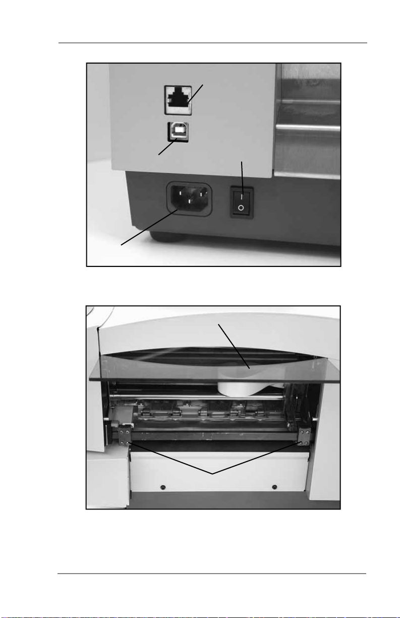
Introduction • 1
Ethernet Connector
USB Connector
Power Receptacle
Printer Interface Panel
Printer Area Door
ON/OFF Switch
Exit Rollers
Exit Rollers and Printer Area Door (Open)
1-9SV61665 Rev. D
Page 17

1 • Introduction
This page is intentionally blank.
1-10 SV61665 Rev. D
Page 18
2 • Printer Basics
In this chapter you'll learn about key printer features and how
to adjust it to meet the requirements of your print jobs.
Printer Features Overview ..................................................2-2
Setting Up a Job .................................................................2-3
1. Setting the Separator Gap .....................................2-3
2. Centering the Input Guide under the Material .......2-5
3. Setting the Feed Angle ..........................................2-6
4. Setting the Feed Ramp ..........................................2-8
5. Position the Side Guide .........................................2-9
6. Loading Material ..................................................2-10
7. Adjusting the Media Thickness Knob ..................2-11
8. Adjusting the Exit Rollers .....................................2-12
9. Printing a Test Piece ............................................2-13
Printer Driver Software .....................................................2-13
Selecting Printer Properties .......................................2-13
Using the Control Panel....................................................2-14
Using the Menus...............................................................2-15
Using the Main Menu .................................................2-16
Using the Setup Menu ...............................................2-17
2-1SV61665 Rev. D
Page 19

2 • Printer Basics
Printer Features Overview
This section provides a brief overview of the printer features. Refer to
Appendix A, Specifications, for detailed specifications for the printer,
including specific requirements for using each type of material.
Speed (pieces per hour)
Printer speed refers to the number of pieces of mail that can be
processed in an hour. The printer can process up to 14,000 #10
or DL envelopes per hour, depending on the address content and
configuration. Printer speed depends on the number of characters
per line, the number of lines, character size, font, interface, barcode,
material size and graphics.
Print Qualities
Draft, Letter, Executive with optional Light Mode
Internal Fonts
13 (14 including Code 3 of 9 Barcode).
Font Size
Font size refers to the size of each typeface. The printer uses from 4
to 144 point size for internal or downloaded fonts.
Media Size
The printer can print on the following range of material sizes.
Width Height Thickness
Minimum 3.5" (89 mm) 3.5" (89 mm) .003" (.08 mm)
Maximum 15.5" (394 mm) 15" (381 mm) .25" (6.35 mm)
Approved Media Types
The printer can be used with envelopes, booklets, catalog envelopes,
postcards, self mailers, and paper. All envelopes must be without
windows. Any folded material needs to be tabbed.
2-2 SV61665 Rev. D
Page 20
Printer Basics • 2
Setting Up a Job
Setting up a print job means adjusting the printer to accommodate
the width, height, thickness and weight of your material.
There are two things that determine how reliably your printer feeds:
the setup adjustments and the quality of your material. A good setup
minimizes misfeeds and jams. And your printer will perform at its best
when you run material that falls within our published specifications.
Please see Appendix A, Specifications for complete material
specifications.
1. Setting the Separator Gap
Whenever you switch from one material type to another, you
need to set the gap between the separators and the feed roller
before printing begins.
NOTE: There are three positions of the "H" Blocks.
• Lever fully down - adjusted to media thickness (ready to
operate).
• Lever midpoint - not adjusted to any media (free floating on
media, not set up to operate).
• Lever fully up - locked in the up position, not adjusted to any
media thickness.
H-Blocks
2-3SV61665 Rev. D
Page 21

2 • Printer Basics
Setting the Proper Feed Gap
A. Loosen the lock knobs to unlock all three H-Blocks.
B. Lift the H-Blocks to their highest position and lock in place.
C. Place a sample piece of material between the separator
fingers (the lower section of the H-Blocks) and the feed
roller.
D. Lower only the H-Blocks that come in direct contact with the
material and let them touch the material.
E. Lock each separator in place. When lowering the H-Blocks,
check that the material is between the separator tabs and
the feed roller.
Setup Example Using #10 or DL Envelopes:
A. When you set the feed gap for a #10 or DL envelope, note
that the width of the envelope will fall completely under the
inside and middle H-Blocks, but only half way under the
outer H-Block. Follow steps B through D to fix this.
B. Remove the side guide.
C. Place a second envelope next to the first, under the outer
H-Block. Place the second envelope flap down with the short
edge under the outer H-Block.
D. Lock the separator in place.
NOTE: If the separator gap is not set properly, the printer will
misfeed.
• If the gap is too big, the printer will feed doubles (two or
more pieces at the same time).
• If the gap is too small, material will jam at the feed roller
entrance.
2-4 SV61665 Rev. D
Page 22
Printer Basics • 2
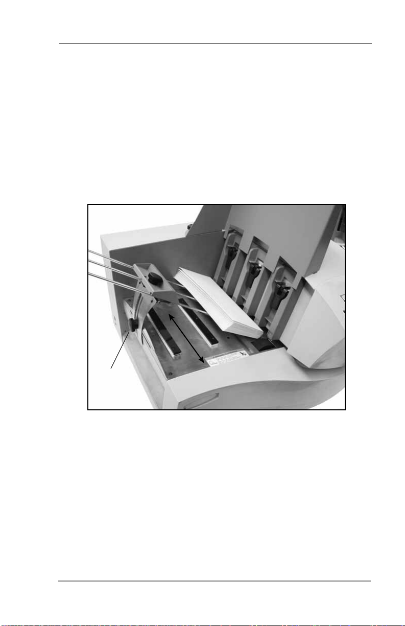
2. Centering the Input Guide under the Material
This adjustment helps eliminate skewing.
A. Place a sample piece of material in the feed area, up against
the support plate.
B. Unlock the knob on the input guide slide by turning
counterclockwise.
C. Slide the input guide forward or back as required to center it
under the sample piece of mail.
D. Turn the lock knob clockwise to secure the input guide.
Knob
Slide input guide forward or
back to center under mail.
2-5SV61665 Rev. D
Page 23
2 • Printer Basics
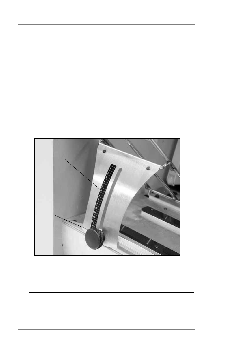
3. Setting the Feed Angle
The height of the input guide depends on the type of material
you're running:
• Heavy material—adjust to a low angle
• Standard material—adjust to the center (45 degree angle)
• Light material—adjust to a high angle
To make the adjustment:
A. Unlock the knob on the input guide slide by turning
counterclockwise.
B. Move the input guide up or down as required by sliding the
retaining knob.
Scale
Knob
C. Turn the lock knob clockwise to secure the input guide.
NOTE: Center line of the knob aligns with relative number of
the scale. Refer to the scale on following page.
2-6 SV61665 Rev. D
Page 24

Printer Basics • 2
1
2
3
4
5
6
7
8
9
10
11
12
13
14
15
The center of the knob aligns in the 6 to 7
range for a typical 8 1/2" x 11" or A4 sheet of
copy paper.
The center of the knob aligns in the 10 to 12
range for a typical # 10 or DL envelope.
The center of the knob aligns in the 14 to 15
range for a typical 90 to 100 lb. (340 to 380
g/m2) stock post card.
NOTE: The settings shown above are suggested settings. You can
adjust the input guide accordingly (up or down) until the desired
feed throughput is achieved.
2-7SV61665 Rev. D
Page 25

2 • Printer Basics
4. Setting the Feed Ramp
A. Slide the ramp to the top of the input guide.
B. With the Feed Gap properly set for one piece of media, slide
the ramp down.
C. Add a stack of media and adjust the ramp downward until
the first piece of media is resting half way down the angle of
the ramp surface as pictured below.
NOTE: This picture is shown without the side guide, for ease
of illustration.
2-8 SV61665 Rev. D
Page 26

Printer Basics • 2
5. Position the Side Guide
Your printer comes with two side guides—a long one and a short
one. Use the long side guide for #10 or DL envelopes and larger
materials. Use the short side guide for materials smaller than a
#10 or DL envelope.
It is important that the side guide not be adjusted tight against
the media.
To position the side guide:
A. Place a sample piece or trial stack of material in the input
area.
B. Slide the side guide until it almost touches the stack of
material.
C. Check that there's about 1/16" (2mm) clearance (the
thickness of a dime) between the side guide and the stack.
NOTE: Proper clearance is important. If you push the side
guide tight up against the stack, it could impede feeding and
cause jams. If the clearance is too great, pieces could skew as
they feed into the printer.
Adjust Side
Guide to media
width.
2-9SV61665 Rev. D
Page 27

2 • Printer Basics
6. Loading Material
Once your printer is set up, you can load material and make a
test print. Avoid misfeeds by following these precautions:
A. Make sure the input area is free of dust and other matter.
B. Take a manageable amount of material and while holding
it as shown, fan all sides of the material to separate each
piece. This step helps keep misfeeds to a minimum.
C. Tamp the material on a flat surface, making sure that the
stack is square.
D. Shingle the stack as you load it into the input area. Load
envelopes so the side to be printed faces up. Flaps should
be down and oriented away from the feed roller (flaps
trailing).
E. Position the right edge of the envelopes flush against the
support plate. Begin with just a few envelopes to start the
stack and get the proper contour, then add several more
pieces. Then, add the remainder of the stack.
NOTE: Envelope feeding is generally more reliable if there
are more than just a couple of envelopes in the input bin.
F. Adjust the position of the feed ramp as described in this
chapter.
2-10 SV61665 Rev. D
Page 28

Printer Basics • 2
7. Adjusting the Media Thickness Knob
The media thickness knob sets the distance between the
printhead and the material. Use it to compensate for different
material thicknesses and to increase clarity of the printing.
A. Estimate the thickness of the material to be run.
NOTE: All material in a run must be the same thickness.
For envelopes with 0 - 2 inserts, start with the media
thickness knob set as shown below. For 1/4" (6mm) thick
material, start with setting all the way at the Thick side. For
1/8" (3mm), start 1/2 way.
B. While running
test samples,
turn the knob
counterclockwise to
close the gap
until the desired
quality of printing
is obtained.
NOTE: Adjusting the media thickness knob too far counter
clockwise may cause smearing or jamming.
A NOTE ABOUT PRINT QUALITY: This printer is designed to
feed and print on a range of materials with various finishes and
coatings. However, the sharpness of the print may vary with
different materials, depending on how absorbent the surface is,
as well as other qualities.
You'll get best results using white wove bonded stock. Printing
is less sharp on Tyvek, recycled and glossy material. It is also
possible that ink may not dry thoroughly on certain very glossy
materials. Always test high gloss materials for their drying
qualities before you buy them in quantity and attempt to run a
print job.
2-11SV61665 Rev. D
Page 29

2 • Printer Basics
8. Adjusting the Exit Rollers
Adjust the exit rollers so they overlap the left and right edges of
the material by 1/4" (6mm). Rotate the release lever to vertical
then slide the rollers from side to side to make the adjustment
and press the lever down to lock. Must be down and latched to
operate.
Exit Roller
Release Lever
IMPORTANT: Make sure the rollers do not touch any printed
area of the material. If this happens, the rollers will act like a
printing press and imprint a faint impression at incremental
distances on the material. If this happens, move the roller or
rollers toward the nearest clear zone, that is, an area free of
printing.
Output Stack Height
The output stacker holds up to five inches of material before
it becomes necessary to remove the stack from the bin. The
optional power stacker increases capacity to 300 #10 or DL
envelopes.
NOTE: As the stack approaches the 5" (130mm) limit, there is
a potential for stacking misfeed (pieces not neatly stacked one
on top of the other). This can cause envelopes to stack out of
printed sequence.
2-12 SV61665 Rev. D
Exit Slide Rollers (in
jam-clearing position)
Page 30

Printer Basics • 2
9. Printing a Test Piece
Print a test piece to ensure the material is loaded properly.
(Or you can use a single test piece if you'd like to check your
setup adjustments.) Use the Control Panel keys to print a test
piece. Refer to Using the Control Panel in this chapter for more
information.
Check the print quality. If it's not what you want, adjust the media
thickness lever as required and run another test piece. When
you're satisfied with the setup adjustments, you're ready to run
the job.
Printer Driver Software
Before you can use your printer with your computer, you must install
a printer driver. The driver gives your computer information about the
printer you're using, and tells the printer about the settings you want
to use in your print job.
If you have not previously installed the printer driver on your
computer, refer to the installation instructions furnished with it.
The printer drivers are contained on a CD that comes with your
printer. To set up, follow the instructions as shown in the installer.
Selecting Printer Properties
This section describes printer properties and use of the windows
for selecting the available options. To access the main properties
window, follow these steps:
1. Click the Start button in the task bar, then select Settings.
2. Click Printers. The Printer window displays.
3. Right click the Pitney Bowes printer icon, then left click the
Properties option.
The Properties window opens and displays seven tabs, each of
which allows access to different printer options. An explanation of the
items on each tab is available by doing the following:
• Right click an item to display the "What's This" button.
• Right or left click this button to display the information about the
selected item.
Options may differ depending on which software drivers are used.
2-13SV61665 Rev. D
Page 31

2 • Printer Basics
Using the Control Panel
Use the buttons on the control panel to get to the printer menus,
define the print options, run a print job, position the print carriage
and turn the printer ON LINE and OFF LINE. You’ll normally perform
these actions from within the application you’re using to set up your
envelope layout.
NOTE: You also have a PC Control Panel which allows you similar
functionality to the LCD menus. The Control Panel also has online
help.
On Line Eject/- Menu Enter Cartridge/+ Test Env.
The buttons on the control panel perform the following functions:
This Button... Does This...
ON LINE
Eject/- (minus)
Menu
2-14 SV61665 Rev. D
Toggles (switches) between ON LINE
(communicates with host) and OFF LINE
(no communications with host). Note that
the functions of two buttons, Eject/- and
Cartridge/+, vary, depending on whether
the printer is ON LINE or OFF LINE .
When printer is OFF LINE, press to eject
the last printed piece from the printer.
When printer is OFF LINE, press to scroll
through menu items from bottom to top
printer.
Displays the options on the Main Menu and
the Setup Menu. The printer must be OFF
LINE to access the menus.
Page 32

This Button... Does This...
Enter
Press to select the currently displayed
menu option.
Printer Basics • 2
Cartridge/+(plus)
Test Env. With the printer OFF LINE, press to print a
With the printer OFF LINE, press to move
the ink cartridge holder to the center of the
printer. This makes it easy to remove the
cartridge. With the printer OFF LINE, press
to scroll forward through the menu options.
test envelope.
Using the Menus
The printer has two menus, both displayed on the LCD:
• Use the Main Menu to control how your printed material looks.
• Use the Setup Menu to configure your printer so it will function
correctly with your computer.
NOTE: The printer must be OFF LINE to access the menu
options.
To select an option:
1. Press the ON LINE button until the LCD message displays OFF
LINE.
2. To access the MAIN MENU, press the Menu button.
3. To access the SETUP MENU, press and hold the Menu button
for four (4) seconds.
4. Press the plus (+) or minus (-) buttons to move through the list
of menu options.
5. When the appropriate menu option appears, press the Enter
button to display the choices associated with that option.
6. Press + or - to scroll through the choices. When an option has an
asterisk (*) in front of it, means that option is presently selected.
(Upon receipt from the factory, the asterisk is typically the default
setting.) When you press the Enter button to define a new
option, an asterisk will appear before the selected option.
7. Press the Menu button several times to back out of the Menu
until the printer displays OFF LINE. Then press the ON LINE
button to print
2-15SV61665 Rev. D
Page 33

2 • Printer Basics
Using the Main Menu
The Main Menu options are:
MAIN MENU MENU OPTIONS
1. ADDRESS LAYOUT A. DISTANCE TO RIGHT
B. DISTANCE TO BOTTOM
C. LINE SPACING
D. INVERTED PRINTING
E. ORIENTATION
F. ORIENTATION CONTROL
2. PRINT QUALITY A. QUALITY
B. LIGHT MODE
3. FONT A. NAME
B. SIZE
C. BOLD
D. ITALIC
4. BARCODE (U.S. Only) A. LOCATION
B. 9 DIGIT ON/OFF
C. BAR WIDTH
5. ADDRESS RECOVERY A. GET ADDRESS (BATCH)
B. GET ADDRESS (INTER)
C. CLEAR MEMORY
6. CLEAR COUNTER
7. IMAGE OVERLAY A. CAPTURE OVERLAY
B. CLEAR OVERLAY
C. PRINT OVERLAY
NOTE: The settings you define in a software application such
as SmartMailer™ override any settings you choose in the printer
menus.
2-16 SV61665 Rev. D
Page 34

Printer Basics • 2
Using the Setup Menu
The Setup Menu Options are:
SETUP MENU MENU OPTIONS
1. HEAVY MEDIA MODE
2. TEST PRINT HEAD
3. PURGE PRINT HEAD
4. LINES PER ADDRESS
5. COMMUNICATIONS A. TCP/IP
B. LINE TERMINATION
6. HEX DUMP MODE
7. LANGUAGE A. SYMBOL SET
B. INCH/MILLIMETER
C. MENU LANGUAGE
8. ENVELOPE FEED DELAY
9. ENVELOPE AUTO EJECT A. AUTO EJECT MODE
B. DELAY
10. ROM REVISION #
11. PRINT HEAD MAINT A. HEAD MAINTENANCE
B. MAINT. CYCLE TIME
12. BUNDLE BREAK
13. TRAY BREAK
14. LOW INK WARNING A. DISPLAY WARNING
15. LOGGING SETTINGS A. ENABLE LOGGING
A. ENABLE/DISABLE
B. BREAK CHARACTER
C. BREAK CHARACTER COUNT
D. CHAR. ORIENTATION
E. BREAK LOCATION
F. PRINT BRK CHARS
G. BRK PAUSE TIME
B. WARNING THRESHOLD
C. STOP WHEN EMPTY
B. LOGGING LEVEL
C. PRINT LOG
NOTE: To print a list of the Main Menu and Setup Menu settings,
press the Test button when ROM REV is displayed.
2-17SV61665 Rev. D
Page 35

2 • Printer Basics
This page is intentionally blank.
2-18 SV61665 Rev. D
Page 36

3 • Printer Maintenance
This chapter describes the maintenance procedures you
should perform on a regular basis to keep your printer running
trouble-free.
Preventive Maintenance .....................................................3-2
Print Quality Problems ........................................................3-2
Cleaning the Exit Rollers ....................................................3-3
Cleaning the Sensor ...........................................................3-3
Cleaning the Printhead Shaft..............................................3-3
Cleaning the Floor Assembly and Top Cover .....................3-4
Purging the Printhead .........................................................3-4
Installing and Removing the Ink Jet Cartridges ..................3-5
Installing the Ink Jet Cartridges (Color & Black) ..........3-5
Removing the Ink Jet Cartridges ..................................3-6
CMYK Printing Alignment (DA75S ONLY) ..........................3-8
3-1SV61665 Rev. D
Page 37

3 • Printer Maintenance
Preventive Maintenance
The Ink Jet Printer is designed for trouble-free service with a minimal
amount of care. You should schedule regular cleaning of the Feed
Rollers, Exit Rollers and Lower Guide.
CAUTION:
• Clean print head, cartridge, ink surfaces and
covers with plain water only. (Water works best!)
• Clean all rubber rollers with isopropyl, denatured
and rubbing alcohol only.
• Use of any other cleaning solvents will void all
warranties.
• Keep petroleum based cleaning solvents away
from rubber or plastic parts. Anything but alcohol
will cause premature breakdown of the rubber
compound.
Print Quality Problems
The print head performs a self cleaning cycle periodically. If print
quality is unacceptable, try the following:
• Adjust the media thickness lever to see if print quality improves.
• Clean the print head cartridge: dampen a soft cotton cloth with
water and wipe the nozzles clean.
Correct Incorrect
• From the Setup Menu, select 3. Purge Printhead. The purging
process clears any clogged ink on the print nozzle. Often this
returns the print quality to a normal level. See Purging the
Printhead in this chapter for more information.
• Install a new ink cartridge. See Installing and Removing Ink Jet
Cartridges in this chapter.
3-2 SV61665 Rev. D
Page 38

Printer Maintenance • 3
Cleaning the Exit Rollers
If the right and left exit rollers are misaligned, that is, contact printed
surfaces, they can become contaminated with ink. Use water to
dampen a soft cloth and remove the ink from the rollers.
Cleaning the Sensor
A film and/or dust can build up on the sensors and cause misfeeds of
the material. Lift the transport door and use compressed air to blow
dust from the sensors. Cans of compressed air are available from
many computer supply houses.
Cleaning the Printhead Shaft
Periodically wipe the printhead shaft clean with a dry, soft, lint free,
cotton cloth. DO NOT OIL!
Printhead Shaft
Sensor
3-3SV61665 Rev. D
Page 39

3 • Printer Maintenance
Cleaning the Floor Assembly and Top Cover
Periodically wipe the cover and floor assembly (feed deck) with a soft
cotton cloth, dampened with water only.
Purging the Printhead
1. To access the SETUP MENU, press and hold the Menu button
for four (4) seconds.
2. Press the + or - buttons to scroll through the SETUP MENU
options until 3. PURGE PRINT HEAD appears on the LCD
panel.
3. Press the Enter button to select this option.
4. To select Purge Printhead cycle, press Enter when the "Purge
Printhead?" message displays.
5. Press the + button (YES) to enable this option. The printer will
display "Please wait...print head being purged".
6. Press the Menu button to back out of the menu until printer
displays "OFF LINE". Then press the ON LINE button to enable
the printer.
3-4 SV61665 Rev. D
Page 40

Printer Maintenance • 3
Installing and Removing the Ink Jet Cartridges
Installing the Ink Jet Cartridges (Color & Black)
The printer uses Ink Jet Cartridges for printing. You must install
a black only cartridge (DA70S), or a black and a color cartridge
(DA75S), before you can print. To begin:
1. With the printer on, press the ON LINE key until the display
reads OFF LINE.
2. Open the back cover of the printer.
3. Press the Cartridge/+ key on the control panel to move the
carriage to the middle of the printer. Do not attempt to move the
carriage by hand. Doing so can result in damage to the carriage
assembly.
4. Remove the cartridge from its shipping container by peeling the
top cover off. Be careful not to touch the gold contacts.
WARNING! The ink in the cartridge may be
harmful if swallowed. Keep new and used
cartridges out of reach of children. Discard empty
cartridges immediately.
5. Gently remove the tape covering the ink nozzles on the print
cartridge, being careful not to touch the copper nozzles.
6. Gently insert the cartridge (color to the right, black to the leftDA750 only) into the carriage at approximately a 20 degree
angle with copper strip to the bottom and in first. Press down on
the cartridge until it is seated.
NOTE: The
print cartridge
photos in this
section are
of the DA75S
printer. The
DA70S has
only one
cartridge.
3-5SV61665 Rev. D
Page 41

3 • Printer Maintenance
7. Push the cartridge forward (away from you) until it snaps in
place.
IMPORTANT: When installing cartridges on the DA75S,
please immediately perform the CMYK Printing Alignment
procedure in this chapter.
Removing the Ink Jet Cartridges
To remove or replace the ink jet cartridges, follow these steps:
1. With the printer on, press the ON LINE button until the printer
displays "OFF LINE".
2. Open the printhead cover.
3. Press the Cartridge/+ key on the control panel. This moves the
carriage to the middle of the printer. Do not move the cartridge
by hand.
3-6 SV61665 Rev. D
Page 42

Printer Maintenance • 3
4. To remove the ink jet cartridge, place your thumb on the grooved
surface and press down slightly then tilt towards you until it pops
loose.
5. Lift the print cartridge out of the cradle.
3-7SV61665 Rev. D
Page 43

3 • Printer Maintenance
CMYK Printing Alignment (DA75S ONLY)
Your DA75S printer allows black (K) to print with color (CMY) at the
same time (known as CMYK printing). To ensure proper printing, the
black (K) and color cartridges (CMY) need to be correctly aligned.
The alignment procedure should be done whenever you replace any
of your cartridges. Follow this procedure to align the cartridges:
1. Turn ON the DA75S. When the startup completes, the "ON
LINE" screen displays.
2. Press the Cartridge/+ button.
3. Replace the ink print cartridge (if you haven't done so already).
The "Press a key when print heads replaced" prompt displays.
Press any key to continue.
4. When the "Reset color (or black) Ink..." prompts displays, press
Cartridge/+ to reset the ink if you have just installed a new
cartridge; otherwise, press Eject/- if all you need to do is the
alignment procedure.
5. When the "ALIGN INK CARTRIDGES" prompt displays, press
(+).
6. When the "--COLOR ALIGNMENT--" prompt displays, insert an
envelope into the printer and press Enter.
7. The "Horiz adjust" prompt displays and the sample shown below
prints on the envelope.
Color
Cartridge
Line on
Top
3-8 SV61665 Rev. D
Select number with best matched lines
123456789
Not Aligned Aligned Not Aligned
10 11 12 13 14 15
Black
Cartridge
Line on
Bottom
Page 44

Printer Maintenance • 3
8. Press the (+) or (-) buttons to scroll through the selections and
choose the number that represents the best horizontal alignment
of the upper and lower lines (for the color and black cartridges,
respectively).
9. Insert an envelope into the printer and press Enter. The
horizontal adjustment prompt displays and the sample shown
below prints on the envelope.
NOTE: The number you selected is highlighted (underlined)
and all lines on the envelope should now be aligned.
Number
Selected
When correct pattern isis sselected
all lines should be strtraight
Highlighted
123456789
Both Black and Color
Cartridge Lines Together
Aligned Aligned
10 11 12 13 14 15
10. Press MENU to return to the alignment choice window
11. Press (+) or (-) to move to the vertical alignment screen.
12. Insert an envelope into the printer and press Enter. The vertical
adjustment prompt displays and the sample shown on the next
page prints on the envelope.
3-9SV61665 Rev. D
Page 45

3 • Printer Maintenance
123456789
Color Cartridge
Line on Top
Black Cartridge
Line on Bottom
Not Aligned Not AlignedAligned
10 11 12 13 14 15
Black Cartridge
Line on Top
Color Cartridge
Line on Bottom
13. Press (+) or (-) to scroll through the selections and choose the
number that represents the best vertical alignment of the upper
and lower lines (for the color and black cartridges, respectively).
14. Insert an envelope into the printer and press Enter. The vertical
adjustment prompt displays and the sample shown on the next
page prints on the envelope.
NOTE: The number you selected will be highlighted and all
lines on the envelope should now be aligned.
3-10 SV61665 Rev. D
Page 46

Printer Maintenance • 3
When correct pattern isis sselected
all lines should be strtraight
Number
Selected
Highlighted
123456789
Both Black and Color
Cartridge Lines Together
Aligned Aligned
10 11 12 13 14 15
15. Press Menu twice to return to the normal ON LINE screen.
3-11SV61665 Rev. D
Page 47

3 • Printer Maintenance
This page is intentionally blank.
3-12 SV61665 Rev. D
Page 48

4 • Troubleshootin
g
This chapter lists some common printer problems and offers
suggestions on how to fix them.
Problems and Solutions......................................................4-2
Feed Problems ...................................................................4-2
Print Quality Problems ........................................................4-3
Interface Problems .............................................................4-4
Motor Problems ..................................................................4-4
Barcode Problems ..............................................................4-5
Other Problems ..................................................................4-6
4-1SV61665 Rev. D
Page 49

4 • Troubleshooting
Problems and Solutions
Before calling for service, look for your problem below. If you can
solve the problem yourself, you will be able to resume printing
sooner.
Feed Problems
Problem Reason Solution
Intermittent
Feed
Multifeeds
(Feeds
Doubles) or
Skewing
Feed Ramp not used. The feed ramp adds a gentle
slope to the stack and helps
feeding. If you're using the
ramp, check the H-Block gap for
proper separation. Also make
sure the wire frame is centered
under the ma te ri al.
See Chapter 2, Printer Basics
for more information.
Dirty feed rollers. Clean the feed roller with
alcohol. DO NOT use any other
solvents or detergents. They
could damage the feed rollers.
Paper dust present
(yellow or white
residue), blocking
feed sensor.
Too much material in
feeder (too heavy).
Weight of stack must
be 20 lbs. (9kg) or
less.
Separators (H-blocks)
not set correctly.
Side guide set
incorrectly.
Media thickness knob
set too thick.
Clean sensor with compressed
air.
See Chapter 3, Printer
Maintenance for more
information.
Remove some material from
stack.
Adjust H-Blocks to thickness of
material.
Check side guide position.
See Chapter 2, Printer Basics
for more information.
Reduce setting.
4-2 SV61665 Rev. D
Page 50

Troubleshooting • 4
Print Quality Problems
Problem Reason Solution
No Print Ink cartridge
problem.
Grey or Light
Print–Black Ink
Off Color
or Low Ink
Intensity
- Color Ink
DA75S Only
Address
Smudging
Address
Printing is not
Sharp
Unwanted
Bolding
Addresses
"Walking"
Ink supply is low. Check adjustment of the media
Incorrect media
thickness knob
setting.
Ink may not dry
on very high gloss
ma te ri al.
Incorrect media
thickness knob
setting. Also,
un suit able material
Escape sequence
turning on bold
or bold se lec tion
in printer's menu
options is set to bold.
Incorrect address
setup.
Purge ink cartridge. See
Chapter 5, Printer Maintenance
for more information.
Clean cartridge jets with soft
cotton cloth and water.
Change to a new cartridge(s)
thick ness knob.
If this fails to correct the
prob lem, replace ink
car tridge. See Chapter 3,
Printer Maintenance for more
information.
Check whether media thickness
knob is adjusted too low.
Try using less glossy material.
Check exit idler rollers.
Check whether media thickness
knob is adjusted too high. Print
quality is less sharp when using
Tyvek®, recycled or glossy
media.
Turn off bolding in software
and/or turn bold selection in
printer menu OFF. Refer to help
system provided with printer for
more information. If prob lem still
exists, call for service.
Count carriage returns and
line feeds and adjust Lines Per
Address to the same number.
Also check line termination:
Typical, CR=CR; LF=LF.
Other choices, (CR=CR+LF;
LF=LF), CR=CR; LF=CR+LF),
(CR=CR+LF; LF=CR+LF),
double spacing.
4-3SV61665 Rev. D
Page 51

4 • Troubleshooting
Interface Problems
Problem Reason Solution
Printer Not
Responding
Motor Problems
Problem Reason Solution
Motor Turning
but No
Feed Roller
Movement
Incorrect printer
driver, bad USB or
Ethernet connection,
bad printer controller
board.
Mechanical problem. Call for service.
Use appropriate printer driver;
replace USB or Ethernet cable.
Make sure cable connections
are tight. If the problem still
persists, call for service.
Clear memory.
Cycle power (turn printer off,
then on).
4-4 SV61665 Rev. D
Page 52

Troubleshooting • 4
Barcode Problems
Problem Reason Solution
Barcode (Lower
Right) is not
Printing (U.S.
Only)
Address too
High
Barcode
Fails MERLIN
Standards at
USPS (U.S.
Only)
Barcode not enabled. Turn barcode ON using
Envelope Designer™ Plus, the
appropriate print driver or the
printer’s control panel menus.
Missing ZIP Code. Insert ZIP Code.
Invalid ZIP Code
format.
Address too low. Verify the bottom of the last line
Address field is
within 1/10” (2.5mm)
of the top edge of the
media.
Mail does not meet
barcode, address
placement, or
other acceptance
tests of MERLIN
(Mail Evaluation
Readability Look-up
Instrument) at USPS.
Check ZIP Code for invalid
character. Example: Zero (0)
can only be the number, not
the letter (O). Verify that there
is a dash inserted between the
5 + 4 ZIP Code per local postal
specifications.
of the address field is not less
than 5/8” (16mm) from bottom
edge of the media.
Move address field down
to within local postal
specifications.
Visit our web site for more
information about MERLIN.
Click on Customer Support,
then search the database for
MERLIN.
4-5SV61665 Rev. D
Page 53

4 • Troubleshooting
Other Problems
Problem Reason Solution
Paper Out or
Paper Jam
Shuttle Jam Media thickness
Out of Memory The printer can run
Input area is empty. Refill the input area.
H-Block separators
not adjusted
correctly.
Paper jam
obstructing paper
path.
Dirty paper feed
sensor.
knob is set too low
for material.
Lower rail shaft dirty Wipe lower rail shaft clean.
out of memory when
downloading fonts or
graphics.
Adjust the H-Blocks to the
thickness of the material you’re
running.
See page Chapter 2, Printer
Basics for more information.
Clear obstructed paper path.
Clean sensor with compressed
air.
See page Chapter 2, Printer
Basics for more information.
Open the transport door and
adjust the media thickness
knob.
See page Chapter 2, Printer
Basics for more information.
This generally means you’re
trying to use a graphic (artwork)
that’s too big or you have too
many fonts or too large a font
size. If the out-of-memory
message appears, try reducing
the size of your art and limiting
the number and size of your
fonts. Then shut the printer
OFF, then ON and retry.
4-6 SV61665 Rev. D
Page 54

Appendix A •
Specifications
This Appendix contains detailed hardware and material
specifications for the printer.
Equipment Specifications ..................................................A-2
Material Specifications.......................................................A-9
A-1SV61665 Rev. D
Page 55

Appendix A • Specifications
Equipment Specifications
Physical Dimensions
13” (33 cm) high; 19” (48 cm) wide; 17” (43 cm) deep (without input
guide).
Weight
50 lbs. (23 kg), including high-capacity print cartridges and catch bin.
Electrical
100-240 Vac, 50/60 Hz., 5.0A
Agency Approvals
cTUVus/TUV Rheinland-GS - Refer to the FCC and CE statements
at the front of this guide for more information.
Interface
USB and Ethernet
Control Language
PCL5, modified
Address Recovery
Memory buffer holds a maximum of 99 addresses
A-2 SV61665 Rev. D
Page 56

Specifications • Appendix A
Print Modes (Print Resolution)
The printer has three print resolutions. These resolutions are
Executive (600), Letter (300), and Draft (150), which represent the
horizontal density. Additionally, there are two Light Mode settings (ON
and OFF), which represent the vertical density. When Light Mode
is "ON", the vertical density setting is 300 DPI; when Light Mode is
"OFF" the vertical density setting is 600 DPI. Refer to the table below
for the print mode options.
Print Quality: With Light Mode
set to "ON":
Executive 600 x 300 DPI 600 x 600 DPI
Letter 300 x 300 DPI 300 x 600 DPI
Draft 150 x 300 DPI 150 x 600 DPI
Fonts
Resident Fonts
Arial, Comic Sans MS, Courier New, Georgia, Impact, Kino, MSLogo,
Symbol, Tahoma, Times New Roman, Trebuchet MS, Verdana,
Webdings, Wingding, an OCR-A font and a Code 39 font. All fonts
are scalable from 4 to 144 point size.
Resident Font Enhancements
Bold, Italic
Downloadable Fonts
Supports bitmapped, downloadable fonts.
Cartridge Fonts
Not Required. Fonts are downloaded with addresses.
With Light Mode
set to "OFF":
User-Definable Parameters
• Font Characteristics
• Address Placement
• Barcode Characteristics
• Print Quality
A-3SV61665 Rev. D
Page 57

Appendix A • Specifications
Barcode Printing Position
The printer can print a barcode in one of three positions:
• lower right of the envelope
• above the address block
• below the address block.
Barcode Printing Types
The printer can print the following barcodes:
1-Dimensional
• The printer is capable of printing a USPS Certified POSTNET
barcode. All types of barcodes can be printable including FIM, 3
of 9, 4 state bar code (UK, Canadian, Euro, Asutralia, etc.) and
others.
• The printer is capable of printing 5-, 9-, or 11- digit POSTNET
barcodes. 5-digit barcode printing may be disabled through
menu selection.
• Delivery point barcode is generated by transmitting the three
digits.
• The printer is capable of printing planet barcode used for delivery
confirmation services. The printer is also capable of printing any
barcode rendered by a Windows
®
true type font.
2-Dimensional
The printer is capable of printing an USPS Certified IBIP barcode
as well as all types of 2-D barcodes defined for the countries
(UK, Canadian, Euro, Australia etc.) and others to the defined
standards. Reference applicable Postal Standards.
A-4 SV61665 Rev. D
Page 58

Specifications • Appendix A
Special Note on FIM Barcode (U.S. Only)
FIM (Face Identifi cation Marking) barcode was developed by the
USPS as part of their POSTNET barcoding system. It is normally
used by high-volume mailers to put on return envelopes for their
customers’ invoices.
When the invoices are mailed back in their return envelope, the
USPS sorts and processes this mail according to what version of
FIM barcode is used on the envelope: FIM A (Postage required,
POSTNET bar code included), FIM C (Postage prepaid, POSTNET
bar code included), and FIM D (Postage required, POSTNET bar
code not included).
One of the requirements of the FIM barcode is that it needs to be
printed on the edge of the envelope (typically printed in the top right
corner). This is diffi cult to support by our printers, especially on on
the trail edge. Inverted mode may supply a better print for the FIM,
but any attempt to print to the exact edge of the envelope is liable to
"miss" the edge occasionally. Because of these issues, we cannot
guarantee full USPS compliance.
Throughput
14,000 letters per hour (lph)
Based on:
• Print quality - Draft mode
• 3-line destination address
• 18 characters per line
• 12-point character size
• Time New Roman font
• Bidirectional printing of text
NOTE: Adding graphics and/or printing at a higher resolution (e.g.,
Letter or Executive mode) will decrease throughput.
Stacker Capacity
• Input Stacker: 600 #10 or DL Envelopes with Bin extension, or
250 without extension installed.
• Output Stacker: 150 #10 or DL Envelopes
A-5SV61665 Rev. D
Page 59

Appendix A • Specifications
Effective Print Area
The printable width is 9.4" (24cm) measured from the right side of
the piece of mail. The printable height is 15" (38cm) measured from
the bottom edge of the piece of mail. See the figure below.
Flap on
Opposite
Trailing Edge (Top)
Feed Direction
Side
Left
Leading Edge (Bottom)
Right
NOTES:
• All edges are viewed from the front surface of the material.
• Two clear zones, each 0.3" (7.6mm) wide, are required on the
piece of mail to allow clearance for the exit rollers.
• Printing is allowed to the top edge of the media, however print
quality will be degraded.
• The lower 5/8" (16mm) of the material is reserved for the lower
right barcode when it is used.
A-6 SV61665 Rev. D
Page 60

Specifications • Appendix A
Printhead/InkJet Cartridges - U.S. Only
Cartridges: User-replaceable ink jet
Single Black Ink Cartridge: Order Number 660-1
Single Color Ink Cartridge: Order Number 660-5 (DA75S only)
4 Pack-Black Ink Cartridge: Order Number 660-9
Print Position Accuracy
For a #10 or DL envelope (Acclaim #10 WW Commercial,Regular):
• Horizontal: within +/- 1.5 mm
• Vertical: within +/- 1.5 mm
• Skew: within +/- 1 degree
For other media:
• Horizontal: within +/- 3.0 mm
• Vertical: within +/- 3.0 mm
• Skew: within +/- 2-1/2 degrees
Environmental Limits
Operating Conditions
• Temperature: 55 to 95°F (12 to 35°C)
• Humidity: 8 to 80%
• Maximum Wet Bulb Temperature: 80°F (27°C)
Storage Conditions
• Temperature (Printer): 15 to 120°F (-23.6 to 35.2°C)
• Humidity (Supplies): 5 to 95%
• Maximum Wet Bulb Temperature: 85°F (29°C)
Shipment Conditions
• Temperature (Printer): -40 to 140°F
• Humidity (Supplies): 5 to 100%
• Maximum Wet Bulb Temperature: 85°F (29°C)
A-7SV61665 Rev. D
Page 61

Appendix A • Specifications
Noise Level
The sound pressure level at the operator's position for this
equipment as measured in any mode using ANSI and ISO Standards
is less than 72 dB(A).
Recommended Usage
This machine has been tested under many different conditions. We
recommend that you do not exceed the usage levels specified below:
• Monthly usage is 250,000 pieces (86,000 pieces per month
typical)
NOTE: Usage beyond these recommended cycles is not
covered under your Equipment Maintenance Agreement.
• Product life is 5 years or 15,000,000 cycles
A-8 SV61665 Rev. D
Page 62

Specifications • Appendix A
Material Specifications
Approved Media
The paper types listed below are approved for use with the printer.
Please note that the dimensional limits above apply in all cases, and
that all media (flats, envelopes, postcards, catalog envelopes, etc.)
must be without windows, unstuffed and unsealed.
• White Wove
• Bond paper
• Recycled paper
• Coated paper
• Card stock
• Brown kraft
• Manila
Material Notes
• Envelopes have a flap along the long edge and are processed
by the printer non-flap edge first. Envelopes may have either a
diagonal or straight edge along the envelope flap.
• Booklets are defined as media having physical dimensions 6 x 9”
(15.25 x 23cm) or larger. Booklets have an opening along their
long edge which is covered by a flap with an adhesive seal.
• Catalog envelopes have an opening along their short edge which
is closed by a flap with an adhesive seal.
• Postcards have no folds or bends. The printable side may have a
higher surface roughness than the non-printable side.
• Self-mailers may be of “C,” “Z,” or half-folded construction. They
may not exceed the maximum allowable thickness as specified
on the previous page and must be tabbed per postal regulations.
• A catalog may consist of multiple pages bound by adhesive or
tabs on the feed edge or at 90 degrees with respect to the feed
edge.
2
• Sheet stock may consist of 16 to 28 lb. (60 to 105g/m
well as 60 to 80 lb. (220 to 300g/m2) coated stock. The size and
thickness constraints specified above apply.
) bond as
A-9SV61665 Rev. D
Page 63

Appendix A • Specifications
Envelope Sizes
Paper Name Displayed in List Size
(Width)
US/Canada Envelope/Paper Sizes
ENV_9 Envelope #9 8⅞"3⅞"
ENV_10 Envelope #10 9½" 4⅛"
ENV_11 Envelope #11 10⅜" 4½"
ENV_12 Envelope #12 11" 4¾"
PPR_Booklet_9_12 Booklet 9 x 12 12" 9"
ENV_MONARCH Envelope Monarch 7½" 3⅞"
PPR_Card_4_6 Card 6 x 4 6" 4"
PPR_Card_5_7 Card 7 x 5 7" 5"
LETTER Letter 8½" 11"
LEGAL Legal 8½" 14"
EXECUTIVE Executive 7¼" 10½ in
European Envelope/Paper Sizes
ENV_B4 Envelope B4 353mm 250mm
ENV_B5 Envelope B5 250mm 176mm
ENV_B6 Envelope B6 176mm 125mm
ENV_C4 Envelope C4 324mm 229mm
ENV_C5 Envelope C5 229mm 162mm
ENV_C6 Envelope C6 162mm 114mm
ENV_C65 Envelope C65 229mm 114mm
PG_ENV_C76 Envelope C76 162mm 81mm
PG_ENV_C7 Envelope C7 114mm 81mm
ENV_DL Envelope DL 220mm 110mm
ENV_DLX Envelope DLX 235mm 120mm
ENV_DLE Envelope DLE 225mm 114mm
A4 A4 210mm 297mm
A5 A5 148mm 210mm
Size
(Height)
A-10 SV61665 Rev. D
Page 64

Specifications • Appendix A
Paper Name Displayed in List Size
(Width)
Asian Envelope/Paper Sizes
Envelope 12JE 140mm 265mm
Envelope 9JE 190mm 265mm
Envelope 6JE 215mm 305mm
Envelope ZL
[China]
Chou #3 Yoko 120mm 235mm
Chou #4 Tate 90mm 205mm
Hagaki 100mm 148mm
Postcard #3 165mm 102mm
Postcard #4 183mm 100mm
Maximum Paper Size 9.4" 15"
230mm 120mm
Size
(Height)
A-11SV61665 Rev. D
Page 65

Appendix A • Specifications
This page is intentionally blank.
A-12 SV61665 Rev. D
Page 66

Appendix B • Glossary
This Appendix contains a glossary of terms related to your
Address Printer and Computer.
B-1SV61665 Rev. D
Page 67

Appendix B • Glossary
Cable
Wires that carry the information between the computer and the
printer.
Character
A printable letter or symbol.
Character height
The height of a uppercase letter. A character height is measured
in points.
Characters per inch
The number of characters printed in a horizontal inch. Also called
pitch.
Character set
The set of characters or symbols that make up a language.
Clean print cartridge
Describes the process of removing dried ink from the nozzles of
the ink jet cartridge.
Configuration
The settings used by the printer to communicate with the
computer. Also the internal settings in the printer that control the
print job.
Control code
The instructions sent to the printer to describe how to perform
the print job.
Control panel
The buttons and display that are used to manually change the
printer’s settings.
CPI
See characters per inch.
Data communications
The sending of data from the computer to a peripheral device,
i.e., the printer.
Dots per inch
The number of ink dots printed in one horizontal inch. The larger
the number the better the resolution of print.
B-2 SV61665 Rev. D
Page 68

Glossary • Appendix B
Double feeding
A condition in which two or more pieces of media feed at the
same time or without separation.
DPI
See dots per inch.
Draft quality
A lower print resolution which saves ink and allows faster printing
of a document.
Drivers
A file used by the computer’s software to communicate
commands and information that the printer needs to layout and
print a document.
Embedded printer commands
Commands sent in a record or document to instruct the printer to
change printing options.
Escape character
A special non-printable character used to instruct the printer to
change printing options.
Escape sequence
Commands sent beginning with the escape character that
instruct the printer to change printing options: fonts, page
orientation, etc.
Feed gap
Adjustable opening between the ends of the H-Block Assembly
fingers and the Feed Rollers so the media is fed one at a time.
Font
A set of printable characters with consistent style and
characteristics.
Grounded
A electrical circuit that has a voltage of zero.
Handshaking
A method for the computer to communicate with peripheral
devices to ensure complete transfer of information.
B-3SV61665 Rev. D
Page 69

Appendix B • Glossary
Hex dump
A printer option that allows all the information and commands
sent to the printer as base 16 digits.
Internal test address message
The preprogrammed Address that is printed when the Test button
is pressed.
Interface cable
The cable that connects the printer or other device to the
computer.
Interface connector
The connectors on both ends of the interface cable that insert
into the interface ports.
Internal fonts
Resident or built-in fonts supplied with a printer.
Jam
See Paper Jam.
Letter quality
Print resolution which saves ink and still provides a high quality
document.
Lines per inch
The number of lines printed in one vertical inch.
Menu directories
The list of available printer controls that appear on the bottom of
the LCD display. A directory can contain other directories called
"sub-directories."
Off Line
A condition in which the printer will not respond to information
sent from the computer.
On line
A condition in which the printer will accept and respond to
information sent from the computer.
Outline fonts
Scaleable printer fonts.
Paper jam
A condition in which media is stuck in the printer.
B-4 SV61665 Rev. D
Page 70

Glossary • Appendix B
Parity
An error checking method used when communicating between
the computer and a peripheral device.
PCL commands
A standard printer language of commands to access printer
features or options.
Point size
A measurement standard for the height of a printed character.
One point equals one seventy-second of an inch.
Postal regulations
Rules and guidelines set up by the Postal Authority for mail.
Power socket
The socket on the back of the printer where the line cord is
connected.
Print cartridge
A removable container that holds ink for printing.
Print quality
Refers to the resolution or level of sharpness of the printed
image.
Printer driver
See Drivers.
Record
A collection of related fields that make up the name and address
of an individual in a mailing list file.
Sans serif
A font typeface that contains no serifs or finishing strokes on the
top or bottom of the characters. Helvetica and Arial are examples
of sans serif typefaces.
Scaleable fonts
Outline printer fonts that are stored in a mathematical form and
can be enlarged or reduced.
Spacing
The relative spacing between characters.
B-5SV61665 Rev. D
Page 71

Appendix B • Glossary
Stuffed media
Media that is already filled and sealed for delivery.
Subdirectory
A directory within a directory (or a folder within a folder).
Troubleshooting
The process of isolating and correcting a problem.
Universal Serial Bus (USB)
A communications protocol for connecting printers and other
peripheral devices to a computer. This protocol supports
automatic device detection for "plug and play" installation. It
also it supports daisy chaining and branching for hot plug-andplay capability without disturbing running applications. USB
also supports the SBP (serial bus protocol) which allows data
transfers to PC peripherals. SBP allows bigger files to be sent
asynchronously across the bus.
There are several USB standards, the latest of which, 2.0,
supports communications up to 480 mb/sec.
The maximum recommended distance of a peripheral to a PC is
16 feet or 5 meters.
B-6 SV61665 Rev. D
Page 72

Inde
x
I-1SV61665 Rev. D
Page 73

Index
A
Addresses "Walking" 4-3
Address High 4-5
Address Recovery
Specifi cation A-2
Address Smudging 4-3
Agency Approvals A-2
Approved Media A-9
Approved Media Types 2-2
B
Barcode (Lower Right) is not
Printing 4-5
Bold Type
Unwanted 4-3
C
Cartridge Fonts A-3
Cleaning
Rubber Rollers 3-2
Cleaning Printhead
Cartridge 3-2
Contact Information iii
Control Language A-2
Control Panel 1-7
D
Downloadable Fonts A-3
E
Effective Print Area A-5
Electrical
Specifi cations A-2
Envelope Sizes A-10
Environmental Limits A-8
Ethernet Cable 1-2
Exit Rollers 2-12
F
Side Guide 2-9
Feed Gap, setting
2-4
Feed Ramp 1-7,2-8
Font Size 2-2
Fuzzy Printing 4-3
G
Getting Help 1-3
Glossary B-2,B-3,B-4,B-
5,B-6
Glossy Material
Print Quality 2-11
H
Heavy Material 2-6
I
Ink Jet Cartridge
Installing 3-5
Removing 3-6
Input Guide 1-7
Input Guide Slide 1-7
Installing
Ink Jet Cartridge 3-5
Interface
USB, Ethernet A-2
Internal Fonts 2-2
J
Jam
Paper 4-6
Shuttle 4-6
I-2 SV61665 Rev. D
Page 74

Index
L
Light Print 4-3
M
Material Notes A-9
Material Safety Data Sheets
iii
Media Size 2-2
Media Thickness Knob 1-7,2-
11,3-2
Memory Card Error 4-6
N
Noise Level A-8
No Print 4-3
O
Operating System
Recommended 1-2
Ordering Supplies iii
Out of Memory 4-6
P
Paper Jam 4-6
Petroleum Based Cleaning
Solvents 3-2
Print
No printing 4-3
Printhead
Purging 3-2
Printing
Light 4-3
Not Sharp 4-3
Test Piece 2-13
Print Modes (Print Resolution)
Available A-3
Print Position Accuracy A-7
Print Qualities 2-2
Purging Printhead 3-2,3-4
R
Recommended Usage A-8
Recycled Material
Print Quality 2-11
Resident Font
Enhancements A-3
Resident Fonts
Listing A-3
S
Separator Gap 2-3
Setup Adjustments
Exit Rollers 2-12
Feed Fence 2-9
Media Thickness Lever
2-11
Output Stack Height 2-12
Separator Gap 2-3
Shingling
Stack 2-10
Shuttle Jam 4-6
Side Guide 1-7
Skew
Avoiding 2-9
Smudging
Address 4-3
Specifications
Address Recovery A-2
Agency Approvals A-2
Approved Media A-9
Cartridge Fonts A-3
Control Language A-2
Downloadable Fonts A-3
Effective Print Area A-5
Electrical A-2
Environmental Limits A-8
I-3SV61665 Rev. D
Page 75

Index
Fonts A-3
Interface A-2
Material Notes A-9
Noise Level A-8
Printhead/InkJet Cartridge
A-8
Print Modes (Print
Resolution) A-3
Print Position Accuracy
A-7
Recommended Usage
A-8
Resident Font
Enhancements A-3
Resident Fonts A-3
Stacker Capacity A-5
Weight A-2
Speed
Printer 2-2
Stacker Capacity A-5
T
Technical Support iii
Test Piece 2-13
Troubleshooting
Address Printing is not
Sharp 4-3
Address Smudging 4-3
Address too High 4-5
Barcode (Lower Right) is
not Printing 4-5
Intermittent Feed 4-2
Memory Card Error 4-6
No Print 4-3
Out of Memory 4-6
Shuttle Jam 4-6
Unwanted Bolding 4-3
Tyvek
Print Quality 2-11
U
Unwanted Bolding 4-3
USB Port
Cable Length 1-2
W
Weight A-2
I-4 SV61665 Rev. D
Page 76

1 Elmcroft Road
Stamford, Connecticut 06926-0700
www.pb.com
Elizabeth Way
Harlow, Essex CM19 5BD
United Kingdom
For Service or Supplies
5500 Explorer Drive
Mississauga, Ontario L4W 5C7
www.pitneybowes.ca
PB Form SV61665 Rev. D 12/06
© 2006 Pitney Bowes Inc.
All Rights Reserved
Printed in the USA or Canada
Printed on recyclable paper
*SV61665ReVD*
 Loading...