

Page 1
AddressRight™ Printer
DA700, DA750
Operator Guide
US English Version
Page 2

FCC Notice
This equipment has been tested and found to comply with the limits for Class A digital device,
pursuant to Part 15 of the FCC Rules. These limits are designed to provide reasonable pro
tection against interference when the equipment is operated in a commercial environment.
This equipment generates, uses, and can radiate radio frequency energy and, if not installed
and used in accordance with the user manuals, may cause harmful interference to radio
communications. Operation of this equipment in a residential area is likely to cause harmful interference in which case the user will be required to correct the interference at this own
expense. Shielded cables must be used with this unit to insure compliance with Class A limits.
Safety EN60950 (IEC950)
This device passes conformity testing to standards for safety of electrical equipment (IECEE)
CB scheme.
These materials and the related software are the confidential and proprietary property of Pitney Bowes Inc., and may not be lent, sold, hired out, or made available to others in any form,
or be disposed of by way of trade in any form without the express written consent of Pitney
Bowes, Inc.
-
Fourth edition, September, 2004 ©2004 Pitney Bowes Inc. All rights reserved.
This book may not be reproduced, in whole or in part in any fashion, or stored in a retrieval
system of any type, or transmitted by any means, electronically or mechanically, without the
express written consent of Pitney Bowes, Inc.
We have made every reasonable effort to insure the accuracy and usefulness of this manual,
however we cannot assume responsibility for errors or omissions or liability for the misuse or
misapplication of our products.
Envelope Designer™ Plus is a registered trademark and PB Supply Line is a service mark of
Pitney Bowes Inc. Microsoft and Windows are trademarks or registered trademarks of Microsoft Corporation.
Page 3

Table of Contents
Chapter 1, DA700/DA750 Overview
Welcome to the DA700/DA750 ...................................... 1-2
Using This Guide ........................................................... 1-2
System Requirements ................................................... 1-4
Getting Help .................................................................. 1-5
Online Help .............................................................. 1-5
Phone Support ......................................................... 1-5
Before You Call ........................................................ 1-5
The World Wide Web ............................................... 1-6
Printer Options .............................................................. 1-7
Ordering Supplies .......................................................... 1-7
Chapter 2, Getting Started with the DA700/DA750
Unpacking the Printer .................................................... 2-2
Package Contents ................................................... 2-3
Choosing a Location for Your Printer .............................
Important Safety Notes .................................................. 2-4
Assembling the DA700/DA750 ...................................... 2-5
1. Attach the Wire Frame to the Printer ................... 2-6
2. Install the Sliding Fence ...................................... 2-7
3. Position the Output Stacker Tray .........................
4. Connect the Parallel Cable or Serial Cable ......... 2-9
5. Connect the Power Cord ..................................... 2-11
Turning On the DA700/DA750 Printer ........................... 2-11
Install the Ink Jet Cartridges (Color & Black) ................. 2-12
Removing the Ink Jet Cartridges ................................... 2-13
Chapter 3, DA700/DA750 Features and Adjustments
Printer Features ............................................................. 3-2
DA700/DA750 Throughput ...................................... 3-3
Material Thickness ................................................... 3-4
Media Size ............................................................... 3-4
Approved Media Types ............................................ 3-4
Setting Up a Job ............................................................ 3-6
1. Set the Separator Gap ......................................... 3-9
2. Center the Wireframe under the Material ............ 3-12
2-4
2-8
iSV61027 Rev. D
Page 4

Table of Contents
3. Set the Feed Angle .............................................. 3-12
4. Set the Wire Frame Ramp ................................... 3-14
5. Position the Feed Fence ...................................... 3-15
6. Load Material ....................................................... 3-16
7. Adjust the Media Thickness Knob ....................... 3-17
8. Adjust the Exit Rollers .......................................... 3-19
9. Print a Test Piece ................................................. 3-21
Chapter 4, Using the DA700/DA750 With Your
Computer
Printer Driver Software .................................................. 4-2
Selecting Printer Properties ........................................... 4-3
Using the Printer Properties Window ............................ 4-4
Selecting the DA700/DA750
from a Windows Application .........................................
Envelope Designer™ Plus ............................................ 4-15
Chapter 5, Printer Maintenance
Preventive Maintenance ................................................ 5-2
Cleaning ........................................................................5-2
Print Quality Problems ................................................... 5-2
Exit Rollers ....................................................................5-3
Sensor ........................................................................... 5-3
Print Head Shaft ............................................................ 5-3
Floor Assembly and Top Cover ...................................... 5-4
CMYK Printing ............................................................... 5-5
Chapter 6, Troubleshooting
Problems and Solutions ................................................ 6-2
Feed Problems ........................................................ 6-2
Print Quality Problems ............................................. 6-3
Interface Problems .................................................. 6-5
Motor Problems ....................................................... 6-5
Barcode Problems ................................................... 6-6
Other Problems ....................................................... 6-7
4-14
ii SV61027 Rev. D
Page 5

Table of Contents
Appendix A, Control Panel Menus
Using the Control Panel ................................................ A-2
Using the Menus ........................................................... A-3
Using the Main Menu .................................................... A-5
Main Menu Diagram ...................................................... A-6
1.Address Layout ..................................................... A-7
2. Print Quality ......................................................... A-11
3. Font Selection ...................................................... A-13
4. Barcode ............................................................... A-15
5. Address Recovery ...............................................
6. Clear Counter ...................................................... A-18
7. Job Settings ......................................................... A-19
Using the Setup Menu ................................................... A-21
Setup Menu Diagram .................................................... A-22
1. Heavy Media Mode .............................................. A-23
2. Test Print Head .................................................... A-24
3. Purge Print Head ................................................. A-24
4. Lines Per Address ............................................... A-25
5. Communications .................................................. A-26
6. Hex Dump Mode .................................................. A-28
7. Language ............................................................. A-31
8. Envelope Feed Delay .......................................... A-33
9. Auto Envelope Eject ............................................ A-34
10. ROM Revision Number ...................................... A-35
A-17
Appendix B, Specifications
Equipment Specifications ..............................................
Material Specifications .................................................. B-9
Index
Index to the Contents of this Manual ............................. i-1
B-2
iiiSV61027 Rev. D
Page 6

Table of Contents
This page is intentionally blank.
iv SV61027 Rev. D
Page 7
Chapter 1
The DA700/DA750
Color Printer Overview
The Pitney Bowes DA700/DA750 is a
versatile, easy-to-use desktop printer
designed for addressing applications.
This chapter explains what's in this
guide, and tells you how to order supplies and where to get more information
about using your
DA700/DA750.
In this chapter:
Welcome to the DA700/DA750
Color Ink Jet Printer .......................... 1-2
Using This Guide .............................. 1-2
System Requirements ...................... 1-4
Getting Help ..................................... 1-5
Printer Options ................................. 1-7
Ordering Supplies ............................. 1-7
Page 8

1 • DA700/DA750 Printer - Overview
Welcome to
the DA700/
DA750 Color
Ink Jet Printer
Using This
Guide
The Pitney Bowes DA700/DA750 color ink jet printer is a
desktop printer used to print addresses, graphics and other
information, in color, on a wide range of material of various
sizes, construction and composition. With the DA700/DA750
you can define the font, placement, print quality and bar
code characteristics for your addresses.
This Operator Guide shows you how to:
• Set up the DA700/DA750 printer
• Connect it to your computer
• Define your envelope layout
• Print a test mail piece
• Send a mail job to the printer from your computer
application.
Refer to this guide for information about printer setup, operation and troubleshooting. It is divided into the following chapters:
Chapter 1, Introduction
Contains an overview of the DA700/DA750 Operator Guide,
information about ordering supplies and a list of help resources.
Chapter 2, Getting Started
Contains instructions for assembling your printer.
Chapter 3, DA700/DA750 Features and Adjustment
Explains how to set up your printer to run a job.
1-2 SV61027 Rev. D
s
Page 9

DA700/DA750 Printer - Overview • 1
Using This Guide
(continued)
Chapter 4, Using the DA700/DA750 With Your
Computer
Contains instructions for installing the printer driver, selecting the printer from your software program and sending a
mail job from your computer.
Chapter 5, Printer Maintenance
Describes how to keep the printer clean and functioning
properly.
Chapter 6, Troubleshooting
Contains a list of possible problems and their solutions.
Appendix A, Control Panel Menus
Explains the Main Menu and Setup Menu options available
on the DA700/DA750 control panel.
Appendix B, Specifications
Provides hardware and material specifications. Your printer
will run at its best when your material conforms to our specifications.
1-3SV61027 Rev. D
Page 10

1 • DA700/DA750 Printer - Overview
System
Requirements
To operate the DA700/DA750 with your computer, your
system must meet the following requirements:
CPU Pentium II 233 MHZ or greater
64 or more MB RAM recom-
mended
Operating System* Windows 98 (2nd Edition),
Windows ME, Windows ME,
Windows 2000, Windows XP
Parallel Cable A parallel cable is supplied with
your printer. If you choose to
use another cable, make sure it
isn't any longer than 10 feet.
or
Serial Cable To use the serial port, a serial
cable of no more 15 feet in
length is required.
* Subject to change.
1-4 SV61027 Rev. D
Page 11
DA700/DA750 Printer - Overview • 1
System
Requirements
(continued)
Microsoft Windows
Operating System
98 and 98 (2nd ed.) June 30, 2006 July 31, 2006 Windows 2000 Pro or XP Pro
Millennium (Me) June 30, 2006 July 31, 2006 Windows 2000 Pro or XP Pro
NT 4.0 June 30, 2003 July 31, 2004 Windows 2000 Pro or XP Pro
XP Home
2000 Professional Mar 31, 2007 Mar 31, 2007 To be determined
XP Professional
* Source: Microsoft.com (posted 1/12/04)
** Dates subject to change, including any change due to Microsoft’s support cessation dates or if USPS
changes requirements. Should dates change, they will be posted on our web site at www.pb.com/sup
port.
Getting Help
Below is a table of the Microsoft operating systems currently
supported and the dates Pitney Bowes expects to stop pro-
viding support for the drivers that run on those systems.
Last Date Pitney Bowes
supports drivers in-
stalled with MS Windows
Microsoft’s “Not
Supported Date”*
Dec 31, 2006 Dec 31, 2006 To be determined
Dec 31, 2008 Dec 31, 2008 To be determined
OS with AddressRight
and DocuMatch**
Recommended
Replacement
As you use your printer, there may be times when you need
help to solve a specific application problem, or you may want
additional information about printer operation. Pitney Bowes
provides several information resources.
-
Online Help
The DA700/DA750 Print Driver has a built-in help system.
Click on Properties from Windows print dialog box. Right
click on items in question for the "What's This" Help button.
If you're using Pitney Bowes programs such as Envelope
Designer™ or SmartMailer™, press the F1 key while you're
using the program to display information about the open
screen. Select the Help menu to display a list of topics or
search for a term. Refer to the documentation supplied with
these programs for more information.
Phone Support
If you need technical support, call Pitney Bowes Technical
Support at: (800) 522-0020.
1-5SV61027 Rev. D
Page 12

1 • DA700/DA750 Printer - Overview
Getting Help
(continued)
(Phone Support, continued)
Before You Call...
Please see Chapter 6, Troubleshooting, for a description of
common problems and their solutions. If you need to call,
please have the following information at hand:
• Model #: W707/W790
• Serial number: See back of unit.
• Nature of problem: What happens and when
does it happen?
• The steps you've already taken to solve the
problem and the results.
The World Wide Web
We encourage you to visit our web site at: http://www.
pb.com\support\
1-6 SV61027 Rev. D
Page 13

DA700/DA750 Printer - Overview • 1
Printer Options
Ordering
Supplies
You'll find the latest information about our products and ser-
vices as well as answers to frequently asked technical ques-
tions.
Pitney Bowes offers several very useful options for your
DA700/DA750:
• Envelope Designer™ lets you create a professional
looking envelope in a matter of seconds—you don't have
to bother with the print driver or make manual
settings.
• The W853 Ink Dryer helps to eliminate smudging on dif
ficult materials like glossy stock.
• The W760 Power Stacker holds up to 300 #10
envelopes. It helps maintain a neat stack in ZIP Code
order when you run long jobs.
You can order supplies for your DA700/DA750 printer directly through the Pitney Bowes Supply LineSM. To place an
order, call:
(800) 243-7824
or
-
Visit our website at:
The following supplies are available for your DA700/DA750
printer:
• Black Ink Cartridge (order number 660-1)
• Color Ink Cartridge (DA750 Only) (order number 660-5)
• 4Pack of Black Ink Cartridges order number 660-9)
• Fast Drying Black Ink Cartridge (TBD)
www.pb.com\supplies\
1-7SV61027 Rev. D
Page 14

1 • DA700/DA750 Printer - Overview
This page is intentionally blank.
1-8 SV61027 Rev. D
Page 15

Chapter 2
Getting Started with
the DA700/DA750
Printer
This chapter explains how to unpack,
assemble and connect your new
printer.
In this chapter:
Unpacking the Printer ..................2-2
Choosing a Location .................... 2-4
Important Safety Notes ................ 2-4
Assembling the
DA700/DA750 .............................2-5
Attach the Wire Frame ................2-6
Install the Sliding Fence ..............2-7
Position the Output Stacker ......... 2-8
Connect the Parallel or
Serial Cable .................................2-9
Connect the Power Cord ........... 2-11
Turn the Printer On .................... 2-11
Install the Ink Jet Cartridge ....... 2-12
Remove the Ink Jet
Cartridge .................................... 2-13
Page 16
2 • Getting Started with the DA700/DA750 Printer
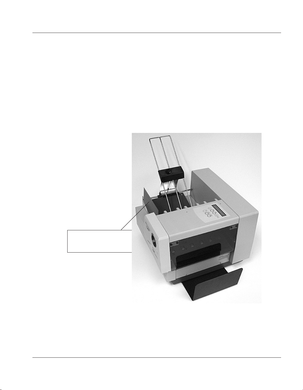
Unpacking
the Printer
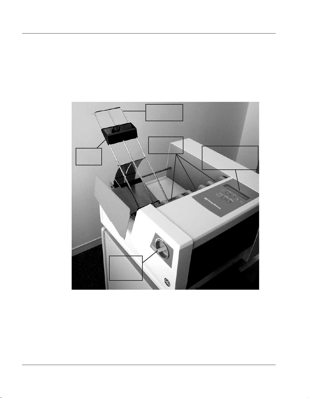
As you remove the DA700/DA750 contents from the box,
note the components of the printer, labeled below.
Wire Frame
Assembly
H-Block
Sliding
Fence
Separators
Control Panel
(LCD Display and
Keypad)
Media
Thickness
Knob
2-2 SV61027 Rev. D
Page 17

Getting Started with the DA700/DA750 Printer • 2
Unpacking
the Printer
(continued)
Package Contents
• DA700/DA750 Printer
• Output Stacker
• Wire Frame with Material Prop, Washer and
Retaining Knob (Input Material Stacker assembled)
• Sliding Fence (long)
• Sliding Fence (short)
• Power Cord
• Parallel Cable
• Printer Operating Guide
• Printer Driver Software
• Ink Jet Cartridge (Black)
(Black & Color for the DA750)
• Operator Training Guide
• POSTNETTM Certificate
• Installation Quality Report
• Print Head Shipment Holder (remove before turning unit
on)
• Quick-Start Instructions
• Shipping Support
(remove before turning unit on)
2-3SV61027 Rev. D
Page 18

2 • Getting Started with the DA700/DA750 Printer
Choosing a
Location for
Your Printer
Important
Safety Notes
Follow these guidelines and safety precautions when selecting a location for your printer:
• Place the printer on a table or other stable, level
surface within the cable’s length (Parallel 10 feet
max.; Serial 15 feet max.) of your computer.
• Allow for adequate space. The DA700/DA750 is 14.7
inches high, 16.2 inches wide and 21.7 inches deep,
without the wire frame input stacker.
• Allow for adequate ventilation around the base and
rear of the printer.
• Protect the printer from heat, dust and moisture.
Avoid placing the printer in direct sunlight.
• To protect against electric shock, plug the machine
into a properly grounded wall outlet.
• DO NOT use an adapter plug. Use of an adapter
could compromise the ground and cause a possible
shock hazard or damage to the equipment in the
event of a short circuit.
• DO NOT remove the ground pin from the line cord.
• Avoid using outlets controlled by wall switches.
Someone could accidently shut your printer off.
• The power cord wall plug is the primary means of
disconnecting the machine from the AC power. The
wall outlet should be near the machine and easily accessible.
• DO NOT route the power cord over sharp edges or
trap it between pieces of furniture.
• Insure that there is no strain on the power cord where
it passes between the equipment, walls or furniture.
• Be certain the area in front of the wall receptacle into
which the machine is plugged is free from obstruction.
2-4 SV61027 Rev. D
Page 19

Getting Started with the DA700/DA750 Printer • 2
Important
Safety Notes
(continued)
Assembling the
DA700/DA750
• DO NOT remove covers. The machine covers serve
to enclose hazardous parts. If the machine has been
dropped or has otherwise had the covers stressed in any
way, report it to your Pitney Bowes Customer Service
Representative.
• To reduce the risk of fire and/or electrical shock, do not
attempt to disassemble this machine. If service is required, contact your Pitney Bowes Customer Service
Representative.
• Keep fingers, loose clothing, jewelry and long hair away
from the moving parts.
• Use only Pitney Bowes approved ink cartridges and
cleaners. Read all instructions before attempting to operate the equipment.
• Follow any specific occupational safety and health stan
dards for your workplace or area.
Once you’ve placed the printer in a suitable location, assemble the printer components in the following order:
NOTE: Do not plug the printer into the power source until
you’ve completed steps 1-4.
-
1. Attach the wire frame input stacker (page 2-6).
2. Install the sliding fence (page 2-7).
3. Position the output stacker (page 2-8).
4. Connect the parallel or serial cable (page 2-9).
5. Attach the power cord and turn the printer ON
(page 2-11).
2-5SV61027 Rev. D
Page 20

2 • Getting Started with the DA700/DA750 Printer
Assembling
the DA700/
DA750
(continued)
Insert the metal sheet into
the height adjustment slot.
Attach the Wire Frame to the Printer.
1. Hook the bottom edge of the wire frame under the de
flector. The wire frame slides between the feed rollers
and the paper deflector. Make sure the front rod is engaged into the key slot bottom.
Slide bottom edge
under here.
-
2. Rotate the wire frame and insert the curved metal sheet
on the bottom of the frame into the height adjustment
slot.
3. Adjust the angle of the wire frame so it’s positioned at
about a 45 degree angle. Turn the lock knob on the side
of the slide clockwise to hold the wire frame in position.
You can adjust both the height and side-to-side position
of the wire frame to accommodate the size and type of
the material you’re running. We talk about this in the next
chapter.
2-6 SV61027 Rev. D
Page 21
Getting Started with the DA700/DA750 Printer • 2
Assembling the
DA700/DA750
(continued)
Install the Sliding Fence
The DA700/DA750 has two fences—a long one and a short
one. Use the short fence when printing material smaller than
a #10 envelope. Use the long fence for larger material.
1. Slide the square edge of the sliding fence into the slots
on the frame slide as shown below.
Insert Sliding Fence
between Slide Guides
and Feed Carriage.
2. The next chapter explains how to set the fence to the
width of the material you’re running.
2-7SV61027 Rev. D
Page 22
2 • Getting Started with the DA700/DA750 Printer
Assembling
the DA700/
DA750
(continued)
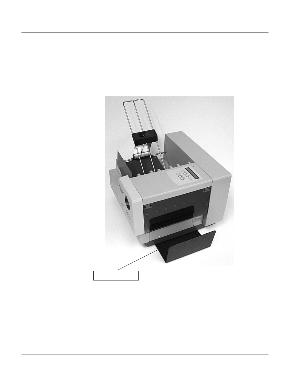
Position the Output Stacker Tray
Printed material is deposited in the output stacker tray. The
tray can stack up to 150 #10 envelopes. Slide it into position
under the back of the printer as shown below.
Stacker Tray
2-8 SV61027 Rev. D
Page 23
Getting Started with the DA700/DA750 Printer • 2
Connecting the
DA700/DA750 to
Your Computer
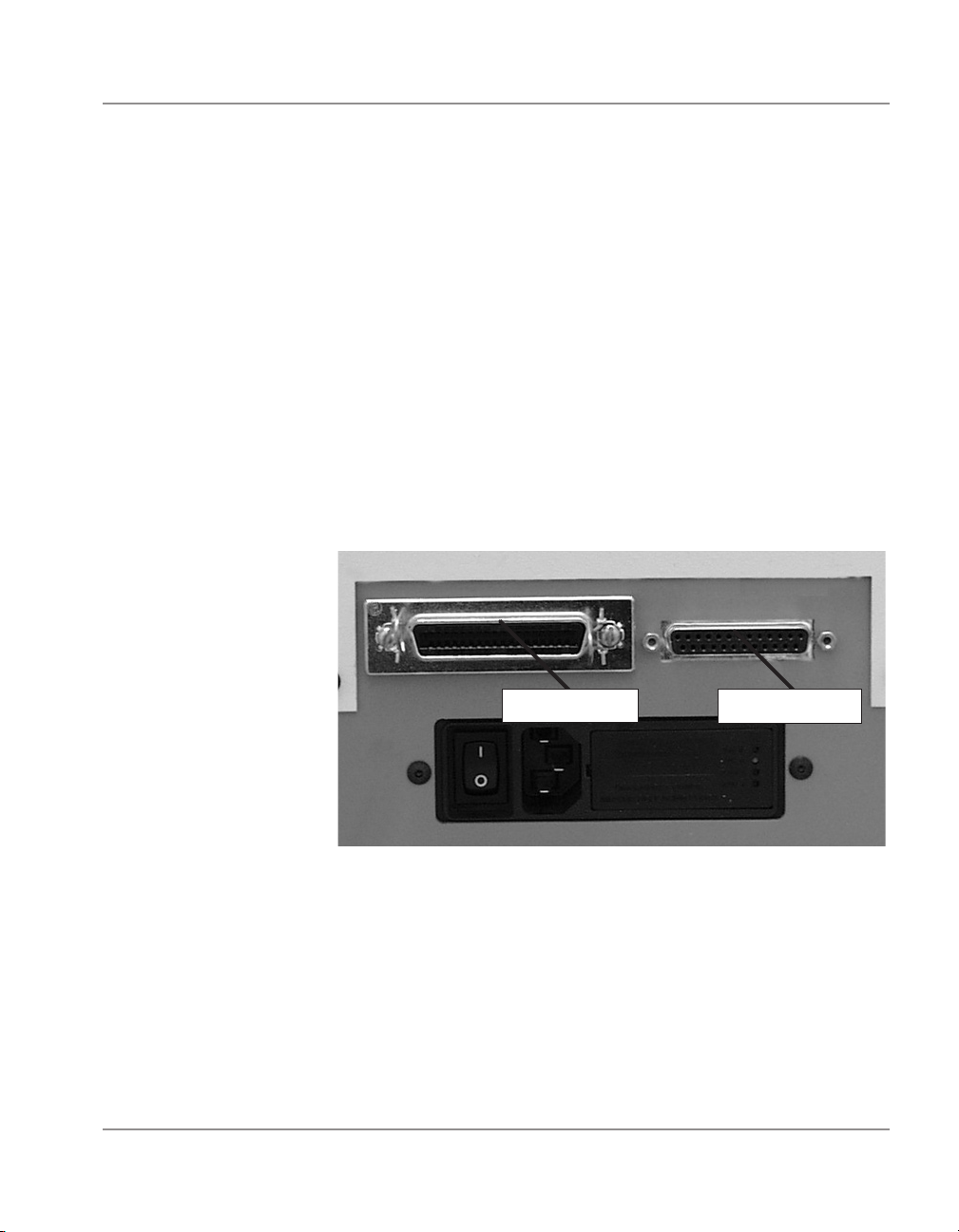
Connecting the Parallel Cable or Serial Cable
Use the parallel cable supplied to connect the DA700/DA750
to your computer, or use an approved serial cable. Each
end of the parallel cable has a connector. One end is labeled
“Printer” and the other is labeled “Computer.”
1. To connect the Parallel Cable (supplied) to the printer,
align the end of the cable connector labeled “Printer” with
the parallel port located on the right side of the printer’s
interface panel, and push the cable connector into the
port. The interface panel is located at the rear of the
printer. It contains the main power switch, the parallel
cable port, the serial port, the power receptacle and fuse.
Parallel Port
2. Secure the connector by snapping the two wire clips
over the corresponding tabs on the connector.
Serial Port
2-9SV61027 Rev. D
Page 24

2 • Getting Started with the DA700/DA750 Printer
Connecting the
DA700/DA750 to
Your Computer
(continued)
3. Align the end of the cable connector labeled “Computer”
with the printer port on your computer and push the cable connector into the port.
4. To connect a Serial Cable (not supplied) to the printer,
align the 25-pin male connector end of the cable with the
serial port on the left side of the printer’s interface. Attach the cable to the printer and the computer’s hex jack
screws using the thumb screws in the connectors.
5. Initialize the printer’s communications port by sending
data to either the parallel or serial port. To change from
the serial port to the parallel port, or vice versa, the printer must be re-initiailized or manually changed through
the setup menu.
2-10 SV61027 Rev. D
Page 25

Getting Started with the DA700/DA750 Printer • 2
Plugging in the
Power Cord
Connecting the Power Cord
1. Connect the power cord to the printer at the interface
panel, shown below.
Power Switch
2. Plug the power cord into a grounded outlet. Please
review the safety information on pages 2-4 and 2-5.
Power Receptacle
Turning on the
DA700/DA750
Once you’ve connected the cable, press the printer’s power
switch to the “|” (ON) position. The switch is located next to
the power cord receptacle.
When you turn the printer on:
• The LCD menu displays that the printer is initializing and
automatically displays “ON LINE”.
• The print head carriage moves to the right and parks in
the maintenance station.
2-11SV61027 Rev. D
Page 26
2 • Getting Started with the DA700/DA750 Printer
Installing and
Removing
the Ink Jet
Cartridge
Install the Ink Jet Cartridges
The printer uses Ink Jet Cartridges for printing (DA750 uses
color and black; DA700 uses black only). You must install a
black and a color cartridge in the DA750 (a black only for the
DA700) before you can print. To begin:
1. With the printer on, press the ON LINE key until the dis
play reads OFF LINE.
2. Open the back cover of the printer.
3. Press the “Replace Print Cartridge” key on the control
panel to move the carriage to the middle of the printer.
Do not attempt to move the carriage by hand. Doing so
can result in damage to the carriage assembly.
4. Remove the cartridge from its shipping container by peel
ing the top cover off. Be careful not to touch the gold con
tacts.
-
-
-
WARNING! The ink in the cartridge may be
harmful if swallowed. Keep new and used
cartridges out of reach of children. Discard
empty cartridges immediately.
5. Gently remove the tape covering the ink nozzles on the
print cartridge, being careful not to touch the copper
nozzles.
2-12 SV61027 Rev. D
Page 27
Getting Started with the DA700/DA750 Printer • 2
Installing and
Removing the
Ink Jet Cartridge
(continued)
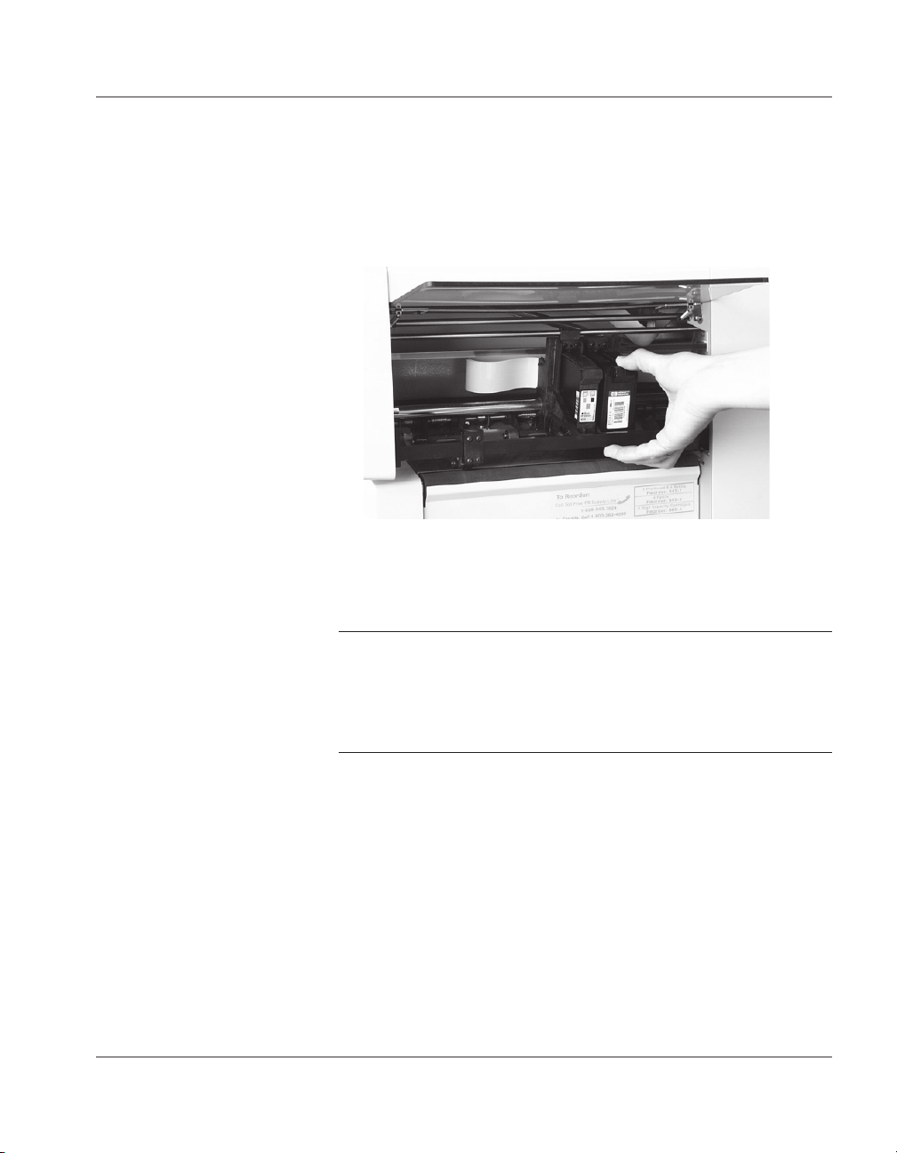
6. Gently insert the cartridge (color to the right, black to the
left-DA750 only) into the carriage at approximately a 20
degree angle with copper strip to the bottom and in first.
Press down on the cartridge until it is seated.
7. Push the cartridge forward (away from you) until it snaps
in place.
IMPORTANT! When installing cartridges in the DA750,
immediately perform the CMYK Printing Alignment pro
cedure. See page 5-5 for instructions.
Removing the Ink Jet Cartridge
When you need to remove or replace the ink jet cartridges,
follow these steps:
1. With the printer on, press the ON LINE key until the dis
play reads OFF LINE.
2. Open the printhead cover of the printer.
2-13SV61027 Rev. D
-
-
Page 28
2 • Getting Started with the DA700/DA750 Printer
Installing and
Removing the
Ink Jet Cartridge
(continued)
3. Press the Replace Print Cartridge key on the control
panel. This moves the carriage to the middle of the printer. Do not move the cartridge by hand.
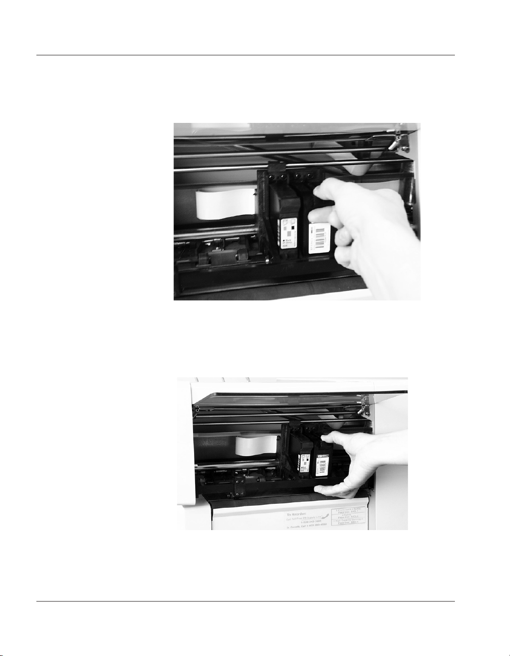
4. To remove the ink jet cartridge, place your thumb on the
grooved surface and press down slightly then tilt towards
you until it pops loose.
5. Lift the print cartridge out of the cradle.
2-14 SV61027 Rev. D
Page 29
Chapter 3
DA700/DA750 Features
and Adjustments
In this chapter you'll learn about key
features of the DA700/DA750 printer
and how to adjust it to meet the requirements of your print jobs.
In this chapter:
Printer Features ........................... 3-2
DA700/DA750 Throughput ..........
Setting Up a Job ..........................3-6
Set the Separator Gap ................3-9
Center the Wire Frame .............. 3-11
Set the Feed Angle ....................
Set the Wire Frame Ramp ......... 3-14
Position the Feed Fence ...........3-15
Load Material ............................. 3-16
Adjust Media
Thickness Knob .........................3-17
Adjust Exit Rollers .....................3-19
Print a Test Piece .......................
3-3
3-12
3-21
Page 30

3 • DA700/DA750 Features and Adjustments
Printer
Features
The DA700/DA750 has the following features:
Speed (Throughput): Refer to chart on next page.
Print Qualities: Draft, Letter, Executive
Internal Fonts: 13 (14 including Barcode)
Optional Font Card
Font Point Size: 4 to 30
Material Thickness: 0.003" to .250"
Speed
Printer speed refers to the number of pieces of mail that
can be processed in an hour. Printer speed depends on the
number of characters per line, the number of lines, character
size, font, interface, barcode, material size and graphics.
Print Qualities
The printer has three selectable print qualities: Draft (fastest speed), Letter (medium speed) and Executive (slowest
speed).
Internal Fonts
A font is a set of characters (letters, numbers and symbols)
that use the same typeface. The DA700/DA750 has thirteen
(plus barcode) different typefaces: Courier, Sans Serif, Ro
man, Baxter, Ding bat, Hancock, Marina, Quincy, Silicon,
Springer, Stencil, and Windmill. You can select these fonts
from the printer control panel menus. If you set up a print job
from your computer, you can use any font that is available
from your software application.
3-2 SV61027 Rev. D
-
Page 31

DA700/DA750 Features and Adjustments • 3
DA700/DA750 Throughput
Throughput specifications for the printer have the following parameters in common: 18
average characters per line; 10 pt character size; Roman font; normal print width; bold off;
parallel interface; each line terminated with CR LF; each address terminated with FF. (All
speeds rated in pieces/hour.)
Printing Black (DA700) / Black with Color Cartridge Removed (DA750)
#10 Envelopes: 600 x 200 dpi 14,000 letters per hour (lph)
600 x 300 dpi 13,000 lph
600 x 600 dpi 11,000 lph
Printing Black, Color Cartridge Installed (DA750 only)
#10 Envelopes: 600 x 200 dpi 11,000 letters per hour (lph)
600 x 300 dpi 10,000 lph
600 x 600 dpi 9,000 lph
Printing Color with Color Cartridge Installed (DA750 only)
Minimum throughputs for destination address (three lines without barcode) in printing with
color cartridge using the H.P. 51641A Head:
#10 Envelopes: 300 x 150 dpi 5,000 letters per hour (lph)
300 x 200 dpi 4,600 lph
300 x 300 dpi 3,000 lph
3-3SV61027 Rev. D
Page 32

3 • DA700/DA750 Features and Adjustments
Printer
Features
(continued)
Font Size
Font size refers to the size of each typeface, and is measured in points. The DA700/DA750 uses from 4 to 30 point
size for internal or downloaded fonts.
Material Thickness
Thickness refers to the size of the material that is processed
through the printer. The DA700/DA750 can handle material
from .003" up to .250" thick.
Media Size
The DA700/DA750 can print on the following range of material sizes.
Width Height Thickness
Maximum 15.5" 15" 25"
(399.4 mm) (381 mm) (6.35 mm
Minimum 3 " 5" .003"
(76 mm) (127 mm) (.0762 mm)
For envelope addressing purposes, the DA700/DA750 is
compatible with any word processor or database application
that can print a mailing label.
Approved Media Types
The printer can be used with the following types of material:
• Envelopes • Postcards
• Booklets • Self Mailers
• Catalog Envelopes • Paper
All envelopes must be without windows, empty and unsealed. Any folded material needs to be tabbed on the lead
ing edge.
Refer to Appendix B, Specifications, for detailed specifications for the DA700/DA750, including specific requirements
for using each type of material.
3-4 SV61027 Rev. D
-
Page 33

DA700/DA750 Features and Adjustments • 3
Printer
Features
(continued)
Other printer features include:
• Ink Jet technology with shuttling head.
• Interface to a standard IBM® compatible
computer.
• Prints USPS POSTNET certified bar code.
• LCD menu display available in seven languages.
• Memory capable of storing up to eight jobs.
• Printing virtually anywhere on an envelope.
• Graphic printing capability.
3-5SV61027 Rev. D
Page 34

3 • DA700/DA750 Features and Adjustments
Setting Up A Job
Setting up a print job means adjusting the printer to accommodate the width, height, thickness and weight of your material. The setup adjustments and the quality of your material
determine how reliably your printer feeds the material.
A good setup minimizes misfeeds and jams. And, your
printer will perform at its best when you run material that
falls within our published specifications. See Appendix B for
complete material specifications.
The figure below calls out key machine adjustments. Each
of these is briefly described starting on the next page. In the
pages that follow, we explain each adjustment in detail.
3
2
1
7
10
9
4
5
3-6 SV61027 Rev. D
6
8
Page 35

DA700/DA750 Features and Adjustments • 3
Setting Up A Job
(continued)
1. H-Block Separators
Adjust to the thickness of your material. The gap between
the H-Block separator fingers and the feed rollers should
be just enough to allow a single piece to feed through the
printer.
2. Interface Panel (Not Shown)
Located on the lower part of the rear cover, the panel has
the ON/OFF switch, parallel cable connector and power
cord receptacle.
3. Wire Frame
Supports the material stack. Adjust the feed angle to ac
commodate the weight of the material you're running.
Adjust its side-to-side position so it's centered under the
stack.
4. Material Prop and Lock Knob
The prop adds a gentle slope to the stack to help feeding.
Adjust so the top of the prop is even with the top of the
stack. Secure the prop with the lock knob.
-
5. Wire Frame Slide and Wire Frame Slide Lock Lever
(Not Shown)
Slides the wire frame side to side. Lock in position with the
lock lever.
6. Feed Fence (Not Shown)
Helps confine the stack. Adjust to the width of your material
plus 1/16" clearance.
3-7SV61027 Rev. D
Page 36

3 • DA700/DA750 Features and Adjustments
Setting Up A Job
(continued)
7. Control Panel
Use the control panel buttons to access printer menus, define print options, run the print job, position the print carriage
and turn the printer on and off line. See Appendix A,
Printer Menus, for detailed instructions.
If you have the DA700/DA750 print driver loaded on your
computer, you can easily perform these functions from within
your software application.
8. Stacker Tray
Printed material is deposited in the stacker (catch) tray. The
tray holds about 5" of material.
9. Exit Rollers (Not Shown)
Guide the printed material as it exits the printer. Adjust so
that each roller overlaps the edge of the material by at least
1/4".
10. Print Area Door Assembly
Open to gain access to the print cartridge and exit rollers.
3-8 SV61027 Rev. D
Page 37

DA700/DA750 Features and Adjustments • 3
Setting Up A Job
(continued)
1. Set the
Whenever you switch from one material type to another, you
need to set the gap between the separators and the feed
roller before printing begins.
NOTE: There are three positions of the "H" Blocks.
• Lever fully down - adjusted to media thickness (ready
to operate).
• Lever midpoint - not adjusted to any media (free
floating on media, not set up to operate).
• Lever fully up - locked in the up position, not adjusted
to any media thickness.
Separator Gap
H-Blocks
Setting the Proper Feed Gap
1. Loosen the lock knobs to unlock all three H-Blocks.
2. Lift the H-Blocks to their highest position and lock in
place.
3. Place a sample piece of material between the sepa
rator fingers (the lower section of the H-Blocks) and
the feed roller.
-
3-9SV61027 Rev. D
Page 38

3 • DA700/DA750 Features and Adjustments
Setting
Up A Job
(continued)
4. Lower only the H-Blocks that come in direct
contact with the material and let them touch the
material.
5. Lock each separator in place. When lowering the HBlocks, check that the material is between the separator tabs and the feed roller.
Setup Example Using #10 Envelopes:
1. When you set the feed gap for a #10 envelope, note
that the width of the envelope will fall completely under the inside and middle H-Blocks, but only half way
under the outer H-Block. Follow steps 2 through 4 to
fix this.
2. Remove the sliding fence.
3. Place a second envelope next to the first, under the
outer H-Block. Place the second envelope flap down
with the short edge under the outer H-Block.
4. Lock the separator in place.
NOTE: If the separator gap is not set properly, the
printer will misfeed.
• If the gap is too big, the printer will feed doubles
(two or more pieces at the same time).
• If the gap is too small, material will jam at the
feed roller entrance.
3-10 SV61027 Rev. D
Page 39

DA700/DA750 Features and Adjustments • 3
Setting Up A Job
(continued)
2. Center the Wire Frame under the Material
This adjustment helps eliminate skewing.
1. Unlock the feed carriage assembly by pushing the
locking lever down.
2. Adjust the feed carriage by aligning with the center of
the media.
3. Lock the feed carriage again by pulling the lever
up.
Locking lever
pushed down
3-11SV61027 Rev. D
Page 40

3 • DA700/DA750 Features and Adjustments
Setting
Up A Job
(continued)
3. Set the Feed Angle
The height of the wireframe input stacker depends on the
type of material you're running:
• Heavy material—adjust to a low angle
• Standard material—adjust to the center (45 degree
angle)
• Light material—adjust to a high angle
To make the adjustment:
1. Unlock the knob on the wireframe slide by turning
counter clockwise.
2. Move the wireframe up or down as required by
sliding the retaining knob.
Lock
Scale
3. Turn the lock knob clockwise to secure the
wireframe.
NOTE: Center line of the knob aligns with
relative number of the scale. Refer to the
scale on following page.
3-12 SV61027 Rev. D
Page 41

DA700/DA750 Features and Adjustments • 3
1
2
3
4
5
6
7
8
9
10
11
12
13
14
15
16
17
18
19
20
Setting Up A Job
(continued)
The center of the knob aligns with number 1 for a typical 3" x 5" post card.
The center of the knob aligns with number 3 for a typical # 10 envelope.
The center of the knob aligns with number 12 for typical 8 1/2" x 11" copy paper.
Note: The above settings are
suggested settings. You can adjust
the wire frame accordingly (up or
down) until the desired feed
throughput is achieved.
3-13SV61027 Rev. D
Page 42

3 • DA700/DA750 Features and Adjustments
Setting Up A Job
(continued)
4. Set the Wire Frame Ramp
Slide Ramp
Upward—Slide the
ramp to the top of
the Wire Frame.
Slide Ramp
Down—With the
Feed Gap properly
set for one piece of
media, slide the ramp
down.
Adjust Ramp to Edge
of Media —Add a stack
of media and adjust the
ramp downward until
the first piece of media
is resting half way down
the angle of the ramp
surface as pictured below (one piece of media
is shown for simplicity).
NOTE: This picture is
shown without the Sliding Fence, for ease of
illustration.
3-14 SV61027 Rev. D
Page 43

DA700/DA750 Features and Adjustments • 3
Setting Up A Job
(continued)
5. Position the Feed Fence
Your printer comes with two feed fences—a long one and a
short one. Use the long fence for #10 envelopes and larger
materials. Use the short fence for materials smaller than a
#10 envelope.
It is important that the sliding fence not be adjusted tight
against the media.
To position the fence:
1. Place a sample piece or trial stack of material in the
input area.
2. Slide the fence until it almost touches the stack of
material.
3. Check that there's about 1/16" clearance (the thickness of a dime) between the fence and the stack.
NOTE: Proper clearance is important. If you push the
fence tight up against the stack, it could retard feeding
and cause jams. If the clearance is too great, pieces
could skew as they feed into the printer.
Adjust Sliding Fence
to media width.
3-15SV61027 Rev. D
Page 44

3 • DA700/DA750 Features and Adjustments
Setting Up A Job
(continued)
6. Load Material
Once your printer is set up, you can load material and make
a test print.
To avoid misfeeds, follow these instructions:
1. Make sure the input area is free of dust and other
matter.
2. Take a manageable amount of material and while
holding it as shown, fan all sides of the material to
separate each piece. This step helps keep misfeeds
to a minimum.
3. Tamp the material on a flat surface, making sure
that the stack is square.
4. Shingle the stack as you load it into the input area.
Load envelopes so the side to be printed aces up.
Flaps should be down and oriented away from the
feed roller (flaps trailing). Position the right edge of
the envelopes flush against the rear wall.
Begin with just a few envelopes to start the stack and
get the proper contour, then add several more pieces.
Then add the remainder of the stack.
5. Adjust the position of the media thickness knob as
described on the next page.
3-16 SV61027 Rev. D
Page 45

DA700/DA750 Features and Adjustments • 3
Setting Up A Job
(continued)
7. Adjust the Media Thickness Knob
The media thickness knob sets the distance between the
printhead and the material. Use it to compensate for differ
ent material thicknesses and to increase clarity of the printing.
1. Estimate the thickness of the material to be run
NOTE: All material in a run must be the same thickness.
For envelopes with 0 - 2 inserts, start with the media thick ness knob set as shown below. For 1/4" thick material,
start with setting all the way at the Thick side. For 1/8",
start 1/2 way.
2. While running test samples, turn the knob
counter-clockwise to close the gap until the desired
quality of printing is obtained.
NOTE: Adjusting the media thickness knob too far
counter clockwise may cause smearing or jamming.
3-17SV61027 Rev. D
Page 46

3 • DA700/DA750 Features and Adjustments
Setting
Up A Job
(continued)
A Note about Print Quality
The DA700/DA750 is designed to feed and print on a range
of materials with various finishes and coatings. However
the sharpness of the print may vary with different materials,
depending on how absorbent the surface is, as well as other
qualities.
You'll get best results using white wove bonded stock. Print
ing is less sharp on Tyvek, recycled and glossy material. It is
also possible that ink may not dry thoroughly on certain very
glossy materials.
Always test high gloss materials for their drying qualities before you buy them in quantity and attempt to run a print job.
A dryer may be needed for high gloss material.
-
3-18 SV61027 Rev. D
Page 47

DA700/DA750 Features and Adjustments • 3
Setting
Up A Job
(continued)
8. Adjust the Exit Rollers
Adjust the exit rollers so they overlap the left and right edges
of the material by 1/4". Rotate the release lever to vertical
then slide the rollers from side to side to make the adjustment and press the lever down to lock. Must be down and
latched to operate.
Exit Roller
Release Lever
IMPORTANT: Make sure the rollers do not touch any
printed area of the material. If this happens, the rollers
will act like a printing press and imprint a faint impression
at incremental distances on the material. If this happens,
move the roller or rollers toward the nearest clear zone,
that is, an area free of printing.
Exit Slide Rollers (in
jam-clearing position)
3-19SV61027 Rev. D
Page 48

3 • DA700/DA750 Features and Adjustments
Setting Up A Job
(continued)
Output Stack Height
The output stacker holds up to five inches of material
before it becomes necessary to remove the stack
from the bin. The optional W760 stacker increases
capacity to 300 #10 envelopes.
NOTE: As the stack approaches the 5" limit, there is a potential for stacking misfeed (pieces not neatly stacked one on
top of the other). This can cause envelopes to stack out of
ZIP Code sequence.
3-20 SV61027 Rev. D
Page 49

DA700/DA750 Features and Adjustments • 3
Setting Up A Job
(continued)
9. Print a Test Piece
1. Make sure material is loaded properly. (Or you can
use a single test piece if you'd like to check that your
setup adjustments are okay.)
2. Turn the printer ON. The ON/OFF switch is located
on the interface panel at the rear of the machine.
Display
On Line
3. Press the ON LINE button on the printer control
panel until the LCD display reads OFF LINE.
4. Press the Test Envelope button. A single envelope
will feed and a sample address should print.
5. Check the print quality. If it's not what you want,
adjust the media thickness knob (page 3-14) as
required and run another test piece.
When you're satisfied with your setup adjustments, you're
ready to run the job. The next chapter explains how to use
the printer with your computer.
Test Envelope
3-21SV61027 Rev. D
Page 50

3 • DA700/DA750 Features and Adjustments
This page is intentionally blank.
3-22 SV61027 Rev. D
Page 51

Chapter 4
Using the
DA700/DA750
With Your Computer
This chapter has instructions for installing the DA700/DA750 printer driver and
using the printer with your computer. It
also briefly explains Envelope Designer™
Plus, the Pitney Bowes envelope design
software that comes with the printer.
In this chapter:
Printer Driver Software ................ 4-2
Selecting Printer Properties ......... 4-3
Using the Printer Properties
Windows ......................................4-4
Selecting the DA700/DA750
from a Windows Application ......
Envelope DesignerTM Plus ......... 4-15
4-14
NOTE: The DA750 is shown in this chapter;
the DA700 is similar. The screen captures
used to illustrate setup options were taken
from the Windows™ 2000 operating system.
Page 52

4 • Using the DA700/DA750 with Your Computer
Printer Driver
Software
Before you can use your printer with your computer, you
must install the DA700/DA750 printer driver. The driver gives
your computer information about the printer you're using,
and tells the printer about the settings you want to use in
your print job.
If you have not previously installed the printer driver on your
computer, refer to the installation instructions furnished with
it.
The printer drivers are contained on the Envelope Designer
Plus CD that comes with your printer. Select "printer drivers"
from the initial screen and follow the on-screen prompts.
The product code is on the label sheet contained in the pack.
4-2 SV61027 Rev. D
Page 53

Using the DA700/DA750 with Your Computer • 4
Selecting
Printer
Properties
This section describes printer properties and how to select
available options. To access the main properties window, follow these steps:
1. Click the "Start" button in the task bar, then select "Set
tings."
2. Click "Printers." The Printer window displays.
3. Right click the Pitney Bowes icon, then left click the
Properties option.
The Properties window opens and displays seven tabs,
each of which allows access to different printer options. Note
that the General tab window displays when the Properties
window opens.
-
To access another option, left click on the appropriate tab.
A window for the selected option displays.
4-3SV61027 Rev. D
Page 54

4 • Using the DA700/DA750 with Your Computer
Selecting Printer
Properties
(continued)
Using the Printer
Properties
Window
NOTE: An explanation of items in each window is also
available by doing the following:
• Right click an item to display the "What's This"
button.
• Right or left click this button to display information
about the selected item.
Use of the window for each tabbed item follows, starting with
the General tab window.
If the General tab window is not currently active, left click the
General tab.
Use the Location area to specify where the printer resides.
You can use alphanumeric characters to designate the site.
For example, if your printer is in building 27 in area C, you
could specify 27/C as the Location entry.
4-4 SV61027 Rev. D
Page 55

Using the DA700/DA750 with Your Computer • 4
Using the Printer
Properties
Window
(continued)
Use the Comment area to make a statement about the
printer. For example, you might want to indicate what the
printer should be used for and when it is available.
If this printer is shared, the comment entered in this area
displays on the computers sharing this printer.
NOTE: The DA700/DA750 printer driver does not support sharing.
Click "Printing Properties" to change the printer's default
settings. Default options include document orientation and
paper source. Click "Advanced" in the Printing Preferences
window to access other settings such as print quality and
paper size.
4-5SV61027 Rev. D
Page 56

4 • Using the DA700/DA750 with Your Computer
Using the
Printer
Properties
Window
(continued)
To display the Sharing window, left click the Sharing tab in
the Properties window.
To configure the printer for private use, choose the "Not
Shared" option. Only the user logged onto the computer will
be able to use this printer.
The window shown here is a standard Windows driver
dialog. It was not developed nor is it supported by Pitney
Bowes.
DO NOT change the settings in this tab; Pitney Bowes does
not support networking of its Envelope printers.
4-6 SV61027 Rev. D
Page 57

Using the DA700/DA750 with Your Computer • 4
Using the
Printer
Properties
Window
(continued)
To display the Port window, left click the Port tab in the
Properties window.
The displayed list shows the available ports, the associated
port monitor, and the printers that use the ports.
To add another port to the display list, click "Add Port." Fol
low the subsequent prompts to identify and name the new
port(s).
To delete a port, select the desired port and then click "De
lete Port."
To set the transmission retry value, click "Configure Port",
enter the desired number of seconds, then click "OK."
-
-
4-7SV61027 Rev. D
Page 58

4 • Using the DA700/DA750 with Your Computer
Using the
Printer
Properties
Window
(continued)
To display the Advanced window, left click the Advanced tab
in the Properties window.
To make the printer available 24/7, select the "Always available" option.
To configure the printer for limited availability, select the
"Available from" option, then enter the desired time frame.
NOTE: If a document is sent to the printer when it is unavailable, the document will be held (spooled) until the printer is
available.
Use the Priority area of this window to rank the status of the
document to be printed. Settings range from 1 to 99, with 1
indicating the highest priority.
4-8 SV61027 Rev. D
Page 59

Using the DA700/DA750 with Your Computer • 4
Using the
Printer
Properties
Window
(continued)
The name of the installed driver displays in the "Driver" area.
This usually matches the name of the print device, however,
for the DA700/DA750, you will see "Pitney Bowes W700/
W790" instead.
To install a new driver, click "New Driver" to launch the Add
Printer Driver Wizard. Follow the prompts to select and install the desired printer driver.
Spooling and Printing Options
Spooling is the process of storing the document on the hard
disk and then sending it to the printer. Right click each option and read the 'What's This?" topic for more information.
Choose the spooling options that best suit your needs:
• To have the document printing in the background, select
the "Spool print documents so program finishes printing
faster" option.
• To ensure that the whole document is ready at the same
time for printing, select the "Start printing after last page
is spooled" option.
• To start printing as soon as the first page of a document
is received by the printer, select the "Start printing immediately" option.
To send the document directly to the printer and by pass
spooling, select the "Print directly to the printer" option.
To direct the printer to check that its setup matches the document setup, select the "Hold mismatched documents."
4-9SV61027 Rev. D
Page 60

4 • Using the DA700/DA750 with Your Computer
Using the
Printer
Properties
Window
(continued)
When the option, "Print spooled documents first", is selected,
the printer operates at maximum efficiency by printing documents that have completed spooling regardless of their designated priority.
To direct the printer to keep printed documents in the queue,
select the "Keep printed documents" option.
To make the printer's advanced features available, select the
"Enable advanced printing features" option.
To change the default document properties:
1. Click "Printing Defaults."
2. Select the default options for document orientation and
paper source.
3. Click "Advanced" to access other settings such as, print
quality and paper size.
4. Click "OK" to return to the Printer Properties window.
To change the default print processor and/or data type:
1. Click "Print Processor...".
2. Select from the options available.
3. Click "OK" to return to the Printer Properties window.
4-10 SV61027 Rev. D
Page 61

Using the DA700/DA750 with Your Computer • 4
Using the
Printer
Properties
Window
(continued)
To display the Color Management window, left click the
Color Management tab in the Properties window.
To allow the system to select the best colors from the available profile, choose the "Automatic" option: this is the manufacturer-recommended choice.
If you want to choose the desired colors, select the "Manual"
option.
Use the color profile portion of this window to:
• Add or remove color profiles associated with this
printer.
• Change the default color profile.
4-11SV61027 Rev. D
Page 62

4 • Using the DA700/DA750 with Your Computer
Using the
Printer
Properties
Window
(continued)
To display the Security window, left click the Security tab
in the Properties window.
Pitney Bowes does not support Networking. Therefore,
adding or removing permissions should not be used.
4-12 SV61027 Rev. D
Page 63

Using the DA700/DA750 with Your Computer • 4
Using the
Printer
Properties
Window
(continued)
To display the Device Settings window, left click the Device
Settings tab in the Properties window.
Pitney Bowes recommends that you leave the manufacturerset default as it is in this window and refer to your envelope
printing application to change envelope sizes.
4-13SV61027 Rev. D
Page 64

4 • Using the DA700/DA750 with Your Computer
Selecting the
DA700/DA750
Printer from
a Windows
Application
The following steps explain how to select the DA700/DA750
printer from a Windows software application. The steps are
similar for most applications. You can also refer to your application's documentation for specific instructions on installing
selecting printers.
1. Start the software application that you use when printing
envelopes with the DA700/DA750 printer and open the
file you want to use.
2. From the File menu, select Print. The Print dialog box ap
pears.
3. Click on the arrow in the Printer Name box. When you
click on the arrow, a drop-down list box appears contain
ing the names of the available printers.
The illustration below shows a typical print dialog box
with the DA750 selected.
-
-
4. Click OK to send the job to the printer.
4-14 SV61027 Rev. D
Page 65

Using the DA700/DA750 with Your Computer • 4
Selecting the
DA700/DA750
Printer from
a Windows
Application
(continued)
Envelope
Designer™
Plus
Once you've made this selection, your print job will automatically go to the DA700/DA750 printer when you select File/
Print provided the DA700/DA750 is selected as the default
printer). Remember to change the printer selection back to
your regular printer for your other printing jobs.
The Pitney Bowes Envelope Designer™ Plus is an easyto-use program that helps you create professional-looking
envelope layouts quickly. With Envelope Designer Plus
you can create and position a mailing address, return address, single-line message, barcode and graphics. Envelope Designer Plus has an extensive online help system
and a Wizard that guides you through the entire design
process.
Envelope Designer™ Plus virtually eliminates the need for
setting up your envelope manually, using either the print
driver options or the printer's control panel menu options.
NOTE: Settings created in Envelope Designer™ Plus will
override the settings entered in Setup on the control panel
of the DA700/DA750.
To access Envelope Designer™ Plus:
1. Click "Start" in the task bar.
2. Select Programs.
3. Select Pitney Bowes Printing, then left click Envelope
Designer™ Plus. The program displays a sample en
velope for you to customize.
-
4-15SV61027 Rev. D
Page 66

4 • Using the DA700/DA750 with Your Computer
This page is intentionally blank.
4-16 SV61027 Rev. D
Page 67

Chapter 5
Printer
Maintenance
This chapter describes the maintenance
procedures you should perform on a
regular basis to keep your printer running trouble-free.
In this chapter:
Preventive Maintenance ..............5-2
Cleaning ......................................5-2
Print Quality Problems ................. 5-2
Exit Rollers ..................................5-3
Sensor ......................................... 5-3
Print Head Shaft .......................... 5-3
Floor Assembly and Top
Cover ...........................................5-4
CMYK Printing Alignment
(DA750 Only) .............................. 5-5
Page 68

5 • Printer Maintenance
Preventive
Maintenance
Cleaning
The Pitney Bowes DA700/DA750 Ink Jet Printer is designed
for trouble-free service with a minimal amount of care. You
should schedule regular cleaning of the Feed Rollers, Exit
Rollers and Lower Guide.
Caution
Clean print head, cartridge, ink surfaces and covers with
plain water only. (Water works best!)
Clean all rubber rollers with the Pitney Bowes Multi-Purpose
Cleaning Kit Number 902-0.
Use of any other cleaning solvents will void all warranties.
Keep petroleum based cleaning solvents away from rubber or plastic parts. Anything but the recommended Pitney
Bowes Cleaning Kit solvent could cause premature breakdown of the rubber compound.
Print Quality
Problems
5-2 SV61027 Rev. D
The print head performs a self cleaning cycle periodically. If
print quality is unacceptable, try the following:
• Adjust the
print quality improves. If the printhead is too high above
the envelope, fuzzy printing results. If the knob is adjusted too low, envelopes jam or print smears.
• From the Setup Menu, select 3.
purging process clears any clogged ink on the print nozzle. Often this returns the print quality to a normal level.
See Appendix A, Control Panel Menus, for information
on using this feature.•
media thickness knob (page 3-18) to see if
Purge Printhead. The
Page 69

Printer Maintenance • 5
Print Quality
Problems
(continued)
Exit Rollers
Sensor
Print Head Shaft
• Clean the print head cartridge: dampen a soft cotton
cloth with water and wipe the nozzles clean (wipe in the
proper directions).
• Install a new ink cartridge (page 2-12).
If the right and left exit rollers are misaligned, that is, contact
printed surfaces, they can become contaminated with ink.
Use water to dampen a soft cloth and remove the ink from
the rollers.
A film and/or dust can build up on the sensors and cause
misfeeds of the material. Lift the transport door and use
compressed air to blow dust from the sensors. Cans of
compressed air are available from many computer supply
houses.
Periodically wipe the print head shaft clean with a dry, soft,
lint free, cotton cloth. DO NOT OIL! Refer to illustration on
the next page.
5-3SV61027 Rev. D
Page 70

5 • Printer Maintenance
Print Head Shaft
(continued)
Floor Assembly
and Top Cover
Print Head Shaft
Sensor
Periodically wipe the cover and floor assembly (feed deck)
with a soft cotton cloth, dampened with water only.
5-4 SV61027 Rev. D
Page 71

Printer Maintenance • 5
CMYK Printing
Alignment
(DA750 ONLY)
Your DA750 printer allows black (K) to print with color (CMY)
at the same time. This is known as CMYK printing. To ensure
proper printing, the black (K) and color cartridges (CMY)
must be correctly aligned. Perform the alignment procedure
below whenever you replace any of your cartridges.
1. Turn ON the DA750. When the startup completes, the
following screen displays.
2. Press plus (+) Replace Print Cartridge.
3. Replace the ink print cartridge if you haven't already
done so. The following prompt displays. Press any key to
continue.
4. When the "Reset color (or black) Ink..." prompt displays,
press plus (+) to reset the ink if you've just installed a
new cartridge; otherwise press minus (-) if you need only
to perform the alignment procedure.
5-5SV61027 Rev. D
Page 72

5 • Printer Maintenance
CMYK Printing
Alignment
(DA750 ONLY)
5. When the "ALIGN INK CARTRIDGES" prompt displays,
press (+ ):
6. When the prompt for horizontal color alignment displays,
insert an envelope into the printer and press ENTER.
7. The following prompt displays and the sample shown on
the next page prints on the envelope.
5-6 SV61027 Rev. D
Page 73

CMYK Printing
Alignment
(DA750 ONLY)
Printer Maintenance • 5
8. Press the (+) or (-) buttons to scroll through the selections (1-15) and choose the number that represents the
best horizontal alignment of the upper and lower lines
(for the color and black cartridges, respectively).
9. Insert an envelope into the printer and press ENTER.
The horizontal adjustment prompt displays and the
sample shown on the next page prints on the envelope.
5-7SV61027 Rev. D
Page 74

5 • Printer Maintenance
CMYK Printing
Alignment
(DA750 ONLY)
NOTE: The number you selected is highlighted
(underlined) and all lines on the envelope should now be
aligned.
10. Press MENU to return to the alignment choice window
11. Press (+) or (-) to move to the vertical alignment screens.
12. Insert an envelope into the printer and press ENTER.
The vertical adjustment prompt displays and the sample
shown on the next page prints on the envelope.
5-8 SV61027 Rev. D
Page 75

CMYK Printing
Alignment
(DA750 ONLY)
Printer Maintenance • 5
13. Press (+) or (-) to scroll through the selections (1-15)
and choose the number that represents the best vertical
alignment of the upper and lower lines (for the color and
black cartridges, respectively).
14. Insert an envelope into the printer and press ENTER.
The vertical adjustment prompt displays and the sample
shown on the next page prints on the envelope.
NOTE: The number you selected will be highlighted and
all lines on the envelope should now be aligned.
5-9SV61027 Rev. D
Page 76

5 • Printer Maintenance
CMYK Printing
Alignment
(DA750 ONLY)
15. Press MENU twice to return to the normal ON LINE
screen.
5-10 SV61027 Rev. D
Page 77

Chapter 6
Troubleshooting
This chapter lists common printer
problems and offers suggestions on
how to fix them.
In this chapter:
Problems and Solutions ..............6-2
Feed Problems ............................ 6-2
Print Quality Problems ................. 6-3
Interface Problems ......................6-5
Motor Problems ........................... 6-5
Barcode ....................................... 6-6
Other Problems ...........................6-7
6-1
Page 78

6 • Troubleshooting
Problems and
Solutions
Feed Problems
Before calling our Technical Operations Center or your Pit
ney Bowes Customer Service Representative, look for your
problem below. If you can solve the problem yourself, you
will be able to resume printing sooner. Also review the FAQs
on our web site.
Problem Intermittent Feed
Reason: Feed Ramp not used.
Solution: The feed ramp adds a gentle slope to the
stack and helps feeding. If you’re using the
prop, check the H-Block gap for proper separation. Also make sure the wire frame is centered
under the material. See Chapter 3.
Reason: Dirty feed rollers.
Solution: Clean the feed roller with the Pitney Bowes Mul
tipurpose Cleaning Kit (Number 902-0).
DO NOT use any other solvents or detergents.
They could damage the feed rollers.
-
-
Reason: Paper dust present (yellow or white residue),
blocking feed sensor.
Solution: Clean sensor with compressed air (see page
5-3).
Reason: Too much material in feeder (too heavy). Weight
of stack must be 20 lbs. or less.
Solution: Remove some material from stack.
6-2 SV61027 Rev. D
Page 79

Troubleshooting • 6
Print Quality
Problems
Problem Multifeed (Feeds Doubles) or Skewing
Reason: Separators (H-blocks) not set correctly. Also
feed fence set incorrectly.
Solution: Adjust H-blocks to thickness of material. See
page 3-10. Check feed fence position. See page
3-16.
Reason: Envelope thickness knob set too thick.
Solution: Reduce setting.
Problem No Print
Reason: Ink cartridge problem.
Solution: Purge ink cartridge (see page A-24).
Clean cartridge jets with soft cotton
cloth and water (in line with color as
shown).
Change to a new cartridge.
Problem Gray or Light Print - Black Ink Off Color or
Low Intensity - Color Ink (DA750 only)
Reason: Ink supply is low, or media thickness knob is set
too high.
Solution: Check adjustment of the media thickness knob
(page 3-18). If this fails to correct the problem,
replace ink cartridge (pages 2-12, 2-13).
6-3SV61027 Rev. D
Page 80

6 • Troubleshooting
Print Quality
Problems
(continued)
Problem Address Printing is not Sharp
Reason: Incorrect media thickness knob setting. Also,
unsuitable material.
Solution: Check whether envelope thickness knob is ad
justed too high (page 3-18).
Print quality is less sharp when using Tyvek,
recycled or glossy media.
Problem Address Smudging
Reason: Incorrect media thickness knob setting. Also,
ink may not dry on very high gloss material.
Solution: Check whether media thickness knob is adjust
ed too low (page 3-18).
Try using less glossy material.
Check exit rollers.
-
-
Problem Unwanted Bolding
Reason: Escape sequence turning on bold or bold selec
tion in printer’s menu options is set to bold.
Solution: Turn off bolding in software and/or turn bold
selection in printer menu OFF. See Appendix A
for instructions. If problem still exists, call Pitney
Bowes for service.
6-4 SV61027 Rev. D
-
Page 81

Troubleshooting • 6
Print Quality
Problems
(continued)
Interface
Problems
Problem Addresses “Walking”
Reason: Incorrect Address Setup.
Solution: Count carriage returns and line feeds and
adjust Lines Per Address to the same number.
Reason: Address Termination should be Form Feed.
Solution: Set Address Setup for 8 lines.
Check Line Termination: Typical, CR=CR;
LF=LF. Other choices, (CR=CR+LF;LF=LF),
(CR=CR;LF=CR+LF), (CR=CR+LF;LF=CR+LF)
Problem No Communications; Printer Does Not
Respond
Reason: Incorrect print driver, bad parallel or serial ca
ble, bad printer controller board.
Solution: Use DA700/DA750 print driver; replace parallel
or serial cable. Make sure cable connections
are tight. If the problem still persists, call Pitney
Bowes for service.
Clear memory (see page A-17).
Cycle power.
-
Motor Problems
Problem Motor Turning but No Feed Roller Movement
Reason: Mechanical problem.
Solution: Call Pitney Bowes for Service.
6-5SV61027 Rev. D
Page 82

6 • Troubleshooting
Barcode
Problems
Problem Barcode (Lower Right) is not Printing
Reason: Barcode not enabled
Solution: Turn barcode ON using Envelope Designer™
Plus, or the DA700/DA750 print driver or the
printer’s control panel menus.
Reason: Missing ZIP Code.
Solution: Insert ZIP Code.
Reason: Invalid ZIP Code format.
Solution: Check ZIP Code for invalid character.
Example: Zero (0) can only be the number, not
the letter (O). Verify that there is a dash inserted
between the 5 + 4 ZIP Code Per DMM specifications.
Reason: Address too low.
Solution: Verify the bottom of the last line of the address
field is not less than 5/8” from bottom edge of
the media.
6-6 SV61027 Rev. D
Page 83

Troubleshooting • 6
Barcode
Problems
(continued)
Other
Problems
Problem Address Too High
Reason: Address field is within 1/10” of the top edge of
the media, or material may be jamming.
Solution: Move address field down to DMM specifica
tions, or correct the jamming.
Problem Barcode Fails MERLIN Standards at USPS
Reason: Mail does not meet barcode, address place-
ment, or other acceptance tests of MERLIN
(Mail Evaluation Readability Look-up Instrument) at USPS.
Solution: For more info on MERLIN, go to PB.com. Select
Support, click on Search the Support Knowledge base, then search the database for MERLIN.
Problem Paper Out or Paper Jam
-
Reason: Input area is empty.
Solution: Refill the input area.
Reason: H-Block separators not adjusted correctly.
Solution: Adjust the H-Blocks to the thickness of the ma-
terial you’re running. See page 3-7.
Reason: Paper jam obstructing paper path.
Solution: Clear obstructed path.
Reason: Dirty paper feed sensor.
Solution: Clean sensor with compressed air. See page
5-3.
6-7SV61027 Rev. D
Page 84

6 • Troubleshooting
Other Problems
(continued)
Problem Shuttle Jam
Reason: Envelope thickness knob is set too low for mate
rial.
Solution: Open the print area door assembly of the print-
er, and adjust the media thickness knob. See
page 3-18.
Reason: Lower rail shaft dirty.
Solution: Wipe lower rail shaft clean. DO NOT OIL!
Problem Memory Card Error
Reason: The card was removed while the printer was
reading it.
Solution: Do not remove the card while the printer is in
use. If the card has been removed, turn the
printer off, re-insert the card, and then turn the
printer on again.
-
Problem Out of Memory
Reason: The printer can run out of memory when down-
loading fonts or graphics.
Solution: This generally means you’re trying to use a
graphic (artwork) that’s too big or you have too
many fonts or too large a font size. If the out-ofmemory message appears, try reducing the size
of your art and limiting the number and size of
your fonts. Then shut the printer OFF, then ON
and retry.
6-8 SV61027 Rev. D
Page 85

Appendix A
Using the Control
Panel Menus
The printer menus are used to control
how your printed material looks. This
appendix describes each menu and
its options.
In this appendix:
Using the Control Panel ............. A-2
Using the Menus ........................ A-3
Using the Main menu ................. A-5
Usind the Setup Menu .............. A-21
Page 86

Appendix A • Control Panel Menus
Using the
Control Panel
Use the buttons on the control panel to get to the printer
menus, define the print options, run a print job, position the
print carriage and turn the printer ON LINE and OFF LINE.
If you’ve installed the
DA700/DA750 printer
driver on your computer,
you’ll normally perform
these actions from within
the application you’re
using to set up your envelope layout. These
settings will override the
control panel settings.
The buttons on the control panel perform the following functions:
This Button... Does This...
ON LINE Toggles (switches) between ON LINE (communi-
cates with host) and OFFLINE (no communications with host).
Eject
Envelope When printer is OFFLINE, press to eject the last
printed piece from the printer.
Menu Displays the options on the Main Menu and the
Setup Menu. The printer must be OFFLINE to access the menus.
A-2 SV61027 Rev. D
Page 87

Control Panel Menus • Appendix A
Using the
Control Panel
(continued)
Using the Menus
The buttons on the control panel perform the following functions:
This Button... Does This...
ON LINE Toggles (switches) between ON LINE (communi-
cates with host) and OFFLINE (no communications with host).
Eject
Envelope When printer is OFFLINE, press to eject the last
printed piece from the printer.
The DA700/DA750 has two menus, both display on the operator panel:
• The Main Menu controls how your printed material looks.
• The Setup Menu is used to configure your printer so it
will function correctly with your computer.
NOTE: The printer must be OFF LINE in order to access the
menu options.
A-3SV61027 Rev. D
Page 88

Appendix A • Control Panel Menus
Using the Menus
(continued)
To select an option:
1. Press the ON LINE button until the LCD message
displays OFF LINE.
2. To access the Main Menu, press the Menu button.
3. To access the Setup Menu, press and hold the Menu
button for four (4) seconds.
4. Press the plus (+) or minus (–) buttons to move through
the list of menu options.
5. When the appropriate menu option appears, press the
Enter button to display the choices associated with that
option.
6. Press + or – to scroll through the choices. When an option has an asterisk (*) in front of it, it means that option
is presently selected.
Upon receipt of the printer from the factory, the asterisk
is typically the default setting.
When you press the Enter button to define a new option,
an asterisk will appear before the selected option.
7. Press the Menu button several times to back out of the
Menu until the printer displays OFF LINE. Then press the
ON LINE button to print.
A-4 SV61027 Rev. D
Page 89

Control Panel Menus • Appendix A
Using the
Main Menu
The Main Menu options are:
1. Address Layout
2. Print Quality
3. Font
4. Barcode
5. Address Recovery
6. Clear Counter
7. Job Settings
NOTE: The settings you define in a software application
such as SmartMailer™ override any settings you choose in
the printer menus.
A-5SV61027 Rev. D
Page 90

Appendix A • Control Panel Menus
Using the
Main Menu
(continued)
Main Menu Menu Options
1. ADDRESS LAYOUT
2. PRINT QUALITY
3. FONT
4. BARCODE
5. ADDRESS RECOVERY
A. DISTANCE TO RIGHT
B. DISTANCE TO BOTTOM
C. LINE SPACING
D. ORIENTATION
E. ORIENTATION CONTROL
DRAFT
EXECUTIVE
LETTER
A. NAME
B. SIZE
C. WIDTH
D. BOLD
E. ITALIC
F. OUTLINE
A. LOCATION
B. 5 DIGIT ON/OFF
C. 9 DIGIT ON/OFF
A. GET ADDRESS
B. CLEAR MEMORY
6. CLEAR COUNTER
7. JOB SETTINGS
CLEAR ADDRESS (YES/NO)
PIECE COUNTERS
A. LOAD
B. SAVE
NOTE: To print a list of the Main Menu and Setup Menu
settings, press the test button when ROM REV is displayed - in the setup Menu.
A-6 SV61027 Rev. D
Page 91

Control Panel Menus • Appendix A
1. Address
Layout
Use the Address Layout option to set up the way an address
appears on the printed material. The printable width is limited
to 9.4” from the right side of the mail piece. The printable
height is 15” measured from the bottom edge of the mail
piece.
A. Distance to Right (Left Margin)
This option sets the start of the address (the left side of the
address) as measured from the right side of the envelope.
For # 10 envelopes this should be about 5.5”.
Press the + or – buttons to increase or decrease the Distance to Right, ( + MORE or – LESS) defined in inches or
millimeters. The left margin is the distance measured from
the right edge of the material to the first printable character.
Press the Enter button to select the desired measurement.
A-7SV61027 Rev. D
Page 92

Appendix A • Control Panel Menus
1. Address
Layout
(continued)
B. Distance to Bottom (Bottom Margin)
Use this option to set the distance from the top address line
to the bottom of the envelope. For #10 envelopes this should
be about two inches.
Press the + or – buttons to increase or decrease the Distance to Bottom, (+ MORE or – LESS) defined in inches or
millimeters. The bottom margin is the distance between the
bottom edge of the material and base of first line of the address.
Minimum distance between the last line of the address and
the bottom edge of the material is 5/8”. If less than 5/8”, the
lower right barcode will not be printed.
Press the Enter button to enable the desired measurement.
A-8 SV61027 Rev. D
Page 93

Control Panel Menus • Appendix A
1. Address
Layout
(continued)
C. Line Spacing
Press the + or – buttons to increase or decrease the Line
Spacing (i.e., 3, 4, 6, 8 lines/inch or Automatic), defined in
lines per inch. Automatic line pitch selection is based on
industry-standard definitions for line spacing for each print
pitch and style selected. The printer will automatically select
the correct setting for the font and size of the characters being printed.
D. Orientation
The choices are Normal and Inverted. Select Normal for
most applications. This tells the printer that the bottom edge
of the material feeds first, with the right side running against
the right side of the printer.
The Inverted option tells the printer that the top edge of the
material feeds first. Select this option if, for example, you
need to feed envelopes flap first.
E. Orientation Control
The choices are Automatic and Manual. When Orientation
Control is set to Automatic, the printer acknowledges the
orientation commands sent from the computer. Setting Ori
entation to Manual notifies the printer to use the menu settings for orientation.
-
A-9SV61027 Rev. D
Page 94

Appendix A • Control Panel Menus
1. Address
Layout
(continued)
To use the Address Layout option:
1. Press the ON LINE button until the display reads OFF
LINE.
2. Press the Menu button to display the Main Menu.
3. Press the + or - buttons to scroll through the Main Menu
options until the address layout option appears on the
LCD panel.
4. Press the Enter button to select this option.
5. Press the + or – buttons to scroll through the address
layout options.
6. Press the Enter button to select the desired option (A, B,
C, D or E).
7. Press the + or - buttons to scroll through the choices as
sociated with each option.
-
8. When you’ve finished making selections, press the menu
button several times to back out of the menu until the
printer displays OFF LINE. Then press the ON LINE button to enable the printer.
A-10 SV61027 Rev. D
Page 95

Control Panel Menus • Appendix A
2. Print
Quality
Use the print quality option to select the resolution of the
printed addresses—Executive, Letter or Draft.
A. Executive Quality
Black - 600 x 600 DPI
Color - 300 x 300 DPI (DA750 only)
This is the darkest of the three print qualities. It prints at the
slowest speed, uses the most ink and delivers the best quality printout. Executive quality prints envelopes that require a
professional appearance.
B. Letter Quality
Black - 300 x 600 DPI
Color - 300 x 200 DPI (DA750 only)
Letter quality is used for envelopes that require a finished,
polished appearance.
C. Draft Quality (150 DPI)
Black - 200 x 600 DPI
Color - 300 x 150 DPI (DA750 only)
This is the lightest of the three and prints at the fastest
speed. Draft quality prints envelopes at the highest speed
and saves ink.
A-11SV61027 Rev. D
Page 96

Appendix A • Control Panel Menus
2. Print Quality
(continued)
To use the Print Quality option:
1. Press the ON LINE button until the display reads OFF
LINE.
2. Press the Menu button to display the Main Menu.
3. Press the + or – buttons to scroll through the Main Menu
options until the Print Quality option is displayed on the
LCD panel.
4. Press the Enter button to select the option you want.
5. Press the + or – buttons to scroll through the Print Qual
ity options, until the desired option (Executive, Letter or
Draft) is displayed on the LCD panel.
6. Press the Enter button to select the desired option.
7. After you’ve made your selection, press the Menu button several times to back out of the Menu until the printer
displays OFF LINE. Then, press the ON LINE button to
enable the printer.
-
A-12 SV61027 Rev. D
Page 97

Control Panel Menus • Appendix A
3. Font
Selection
The DA700/DA750 has thirteen available fonts (typefaces,
plus barcode): Courier, Sans Serif, Roman, Baxter, Hancock,
Marina, Quincy, Silicon, Springer, Stencil, Windmill, Alpine,
OCR A and Code 39. All fonts are scalable from 4 to 30 point
size, and can be printed in regular, bold, italic. and outline
style.
The DA700/DA750 also supports downloaded fonts. This
means that if you are using Windows, all the fonts installed
in Windows are available. This also applies to any DOS™
applications that can download fonts. The options on this
menu are Name, Size, Width, Bold, Italic and Outline.
A. Name
The printer has thirteen internal fonts as described above,
and one barcode font.
B. Size
The font size (internal or external) can be set from 4 to 30
point.
C. Width
The font width is Normal (100%), thin (75%), condensed
(50%), wide (125%) or expanded (150%).
D. Bold
This is the darkest imprint because character stroke weight
(thickness of print) is increased. Use Bold to emphasize or
highlight text in an address.
A-13SV61027 Rev. D
Page 98

Appendix A • Control Panel Menus
3. Font Selection
(continued)
E. Italic
Italic characters have decreased stroke weight, print at an
oblique angle and print somewhat lighter than standard or
bold typefaces. Use italic to provide emphasis and add flair
to address text that requires a finished, polished appearance.
F. Outline
Use this option to print only the outline or the edge of the
font’s shape. All records printed using Outline will appear as
hollow text.
To select the font options:
1. Press the + or – buttons to scroll through the Main Menu
options until the Font option appears on the LCD panel.
2. Press the + or – buttons to scroll through the Font options until the desired option appears on the LCD panel.
3. Press the Enter button to select the desired option (A, B,
C, D, E or F).
4. After you’ve made your selections, press the Menu but
ton several times to back out of the Menu until the printer
displays OFF LINE. Then, press the ON LINE button to
enable the printer.
A-14 SV61027 Rev. D
-
Page 99

Control Panel Menus • Appendix A
4. Barcode
Use this option to include a USPS-certified barcode on your
mailpieces. The DA700/DA750 can print a 5- or 11-digit barcode. If you select Off, it means that if the computer sends a
5-digit ZIP Code, it won’t print a barcode; only the 9-digit ZIP
Codes and Delivery Points will print.
The options on the barcode menu are Location and 5-Digit
On/Off.
A. Location
Press the Enter and + buttons to select the Location where
you want the barcode to print. (Lower Right Corner, Above
Address, Below Address or turn Barcode Off).
B. 5-Digit On / Off
If a 5-digit barcode is required, selecting the 5-digit barcode
option (5-Digit ON) lets you print either
5-digit or 11-digit barcodes as requested by the computer.
1. Press the + or – buttons to scroll through the Main Menu
options until the Barcode option appears on the LCD
panel.
2. Press the Enter button to select this option.
3. Press the + or – buttons to scroll through the Barcode
options, until the desired option
(A. Location and B. 5-Digit On/Off) is displayed on the
LCD panel.
4. Press the Enter button to select an option.
Use this option to define where the U.S. POSTNET™
Barcode will print.
A-15SV61027 Rev. D
Page 100

Appendix A • Control Panel Menus
4. Barcode
(continued)
5. Press the Enter button at the 5-digit barcode prompt and
use + or – to turn the option ON or OFF.
6. When you finish making your selections, press the Menu
button several times to back out of the menu until the
printer displays OFF LINE. Then, press the ON LINE button to enable the printer.
C. 9-Digit On / Off
If a 9-digit barcode is required, selecting the 9-digit barcode
option (9-Digit ON) lets you print ONLY a 9-digit barcode.
NO 11 DIGIT BARCODE WILL PRINT
1. Press the + or – buttons to scroll through the Main Menu
options until the BARCODE option displays on the LCD
panel.
2. Press the Enter button to select this option.
3. Press the + or – buttons to scroll through the Barcode
options, until the desired option (A. Location and B. 5Digit On/Off) displays on the LCD panel.
.
4. Press the Enter button to select an option.
Use this option to define where the U.S. POSTNET™
Barcode will print.
5. Press the Enter button at the 5-digit barcode prompt and
use + or – to turn the option ON or OFF.
6. After making your selections, press the Menu button
several times to back out of the menu until the printer
displays OFF LINE . Then, press the ON LINE button to
enable the printer.
A-16 SV61027 Rev. D
 Loading...