

Pioneer XPRS10, XPRS12, XPRS215S, XPRS15, XPRS115S User Manual
XPRS Series
XPRS10
XPRS12
XPRS15
XPRS115S
ACTIVE LOUDSPEAKER / ACTIVE SUBWOOFER
HAUT-PARLEUR ACTIF / CAISSON DE BASSES ACTIF
AKTIVLAUTSPRECHER / AKTIV-SUBWOOFER
DIFFUSORE ATTIVO / SUBWOOFER ATTIVO
ACTIEVE LUIDSPREKER / ACTIEVE SUBWOOFER
ALTAVOZ ACTIVO / ALTAVOZ DE SUBGRAVES ACTIVO
ALTO-FALANTE ATIVO / SUBWOOFER ATIVO
АКТИВНЫЙ ГРОМКОГОВОРИТЕЛЬ /АКТИВНЫЙ САБВУФЕР
アクティブラウド スピーカー/アクティブ サブウーファー
XPRS215S
http://pioneerproaudio.com
The Pioneer DJ support site shown above offers FAQs, information on software and various other types of
information and services to allow you to use your product in greater comfort.
Le site de support DJ de Pioneer indiqué ci-dessus propose une FAQ, des informations sur le logiciel et divers
types d’informations et de services qui permettent une utilisation plus confortable de ce produit.
Die oben gezeigte Pioneer DJ-Support-Website enthält häufig gestellte Fragen, Informationen über Software
und andere wichtige Informationen und Dienste, die Ihnen helfen, Ihr Produkt optimal zu verwenden.
Il sito di supporto DJ Pioneer indicato qui sopra offre una sezione FAQ, informazioni sul software ed
informazioni e servizi di vario tipo, per permettere un uso più confortevole dei nostri prodotti.
De bovengenoemde Pioneer DJ ondersteuningswebsite biedt een overzicht van de vaak gestelde vragen,
informatie over software en allerlei andere soorten informatie en diensten die u in staat stellen dit product met
meer gemak te gebruiken.
El sitio de asistencia Pioneer DJ mostrado arriba ofrece las preguntas frecuentes, información del software y
varios otros tipos de información y servicios que le permitirán usar su producto con mayor confort.
O site de suporte da Pioneer DJ mostrado acima oferece FAQs, informações sobre o software e outros tipos
de informações e serviços para permitir utilizar o produto com um maior conforto.
На указанном выше сайте поддержки Pioneer DJ содержатся раздел часто задаваемых вопросов,
информация по программному обеспечению, а также различные другие типы информации и услуг,
позволяющие использовать ваше изделие наиболее эффективно образом.
上記のPioneerDJサポート サイトでは、困ったときのよくある質問やソフトウェア の情報など、より快適に製品をお使い
いただくための各種情報やサービスを提供しております。
Português Русский
商品相談・修理受付・付属品購入窓口のご案内
お取り扱いにお困りのとき、本書の巻末をご覧ください。
Operating Instructions
Mode d’emploi
Bedienungsanleitung
Istruzioni per l’uso
Handleiding
Manual de instrucciones
Manual de instruções
Инструкции по эксплуатации
取扱説明書
保証書付き
日本語Français Deutsch ItalianoEnglish Nederlands Español
Introduction
XPRS215S
4
1
2
3
XPRS10, XPRS12, XPRS15
4
3
XPRS115S
How to Read This Document
Thank you for purchasing a Pioneer DJ product. To ensure you can maximize the functions of this device and use them effectively, please
read this Operating Instructions and Important Safety Precautions thoroughly for correct use.
Please be sure to read in particular the Important Safety Precautions, and keep the Operating Instructions and Important Safety
Precautions together with the Warranty.
For more information on installation, please read the Installation Manual.
http://pioneerproaudio.com
Main Features
2 400-W high output and high sound quality are achieved
by mounting a D-class amplifier module of the professional
amplifier leading company Powersoft in a wooden cabinet
featuring outstanding acoustic characteristics.
The XPRS can be used not only as a stationary sound system in
a stationary facility but also as sound equipment for events as it
can be easily transported and set up quickly.
High sound quality design of wooden cabinet structure
g
featuring outstanding acoustic characteristics
A wooden cabinet is employed to provide superior sound quality
in all models.
The cabinet made of highly rigid materials features outstanding
acoustic characteristics and reproduces clear sound quality
ranging from a minute sound to a powerful sound.
Equipped with a high-efficiency and high-power class-D
g
amplifier module
The XPRS is equipped with a D-class amplifier module realized
by the technology of Powersoft and achieves a 2 400-W (at peak)
high output comparable with that of a large power amplifier.
A very high power efficiency can reduce the energy required to
get the same output power.
Advanced protective functions preventing field problems
g
A variety of functions such as status monitoring and limiter
functions reliably protect the driver, amplifier, and power supply
by using advanced DSP control. Protective circuits designed to
meet the reliability requirements for professional use prevent
problems in the field.
A variety of I/O terminals enabling flexible system connections
g
A mixing function is available which mixes multiple input
sources and outputs them. In addition, a through output terminal
is available to make it easy to connect with full-range speakers
and multiple subwoofers.
Four EQ modes enabling a quick system setup (full-range
g
models)
Four EQ modes of FLAT, BASS+, SPEECH, and WEDGE are
available which enable selection of the optimum acoustic
characteristic to suit the application by just selecting a switch.
Multi-angle pole socket enabling installation of a pole at
g
two angles (full-range models)
Two angles of 0 and 7 can be selected to suit the size of the venue
when installing the speakers using a pole.
Confirm All Accessories
Power cords
Installation and Operation Manual (this document)
Important Safety Precautions
The contents of the warranty for the United States and Canada are
provided on the last pages of the instructions in English and French.
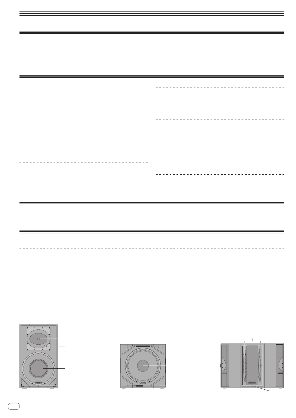
Names and Functions of Parts
Front Panel Facilities
Tweeter
1
1-inch throat 1.75-inch diaphragm compression driver
Rotatable horn (XPRS12, XPRS15)
2
This is a constant directivity horn that can be rotated.
• Factory default directivity: 90 degrees horizontally and 60
degrees vertically
• Directivity when turned 90 degrees: 60 degrees horizontally
and 90 degrees vertically
Horn (XPRS10)
2
This is a constant directivity horn with directivity of 90 degrees
horizontally and 60 degrees vertically.
* Horn rotation is not possible for XPRS10.
Woofer
3
FRONT LED indicator
4
This is a white LED indicator. Lighting is in accordance with the
FRONT LED setting on the rear panel.
For details on the settings, see the explanation of the rear panel.
3
2way full-range model
En
2
Subwoofer model
Subwoofer model
4

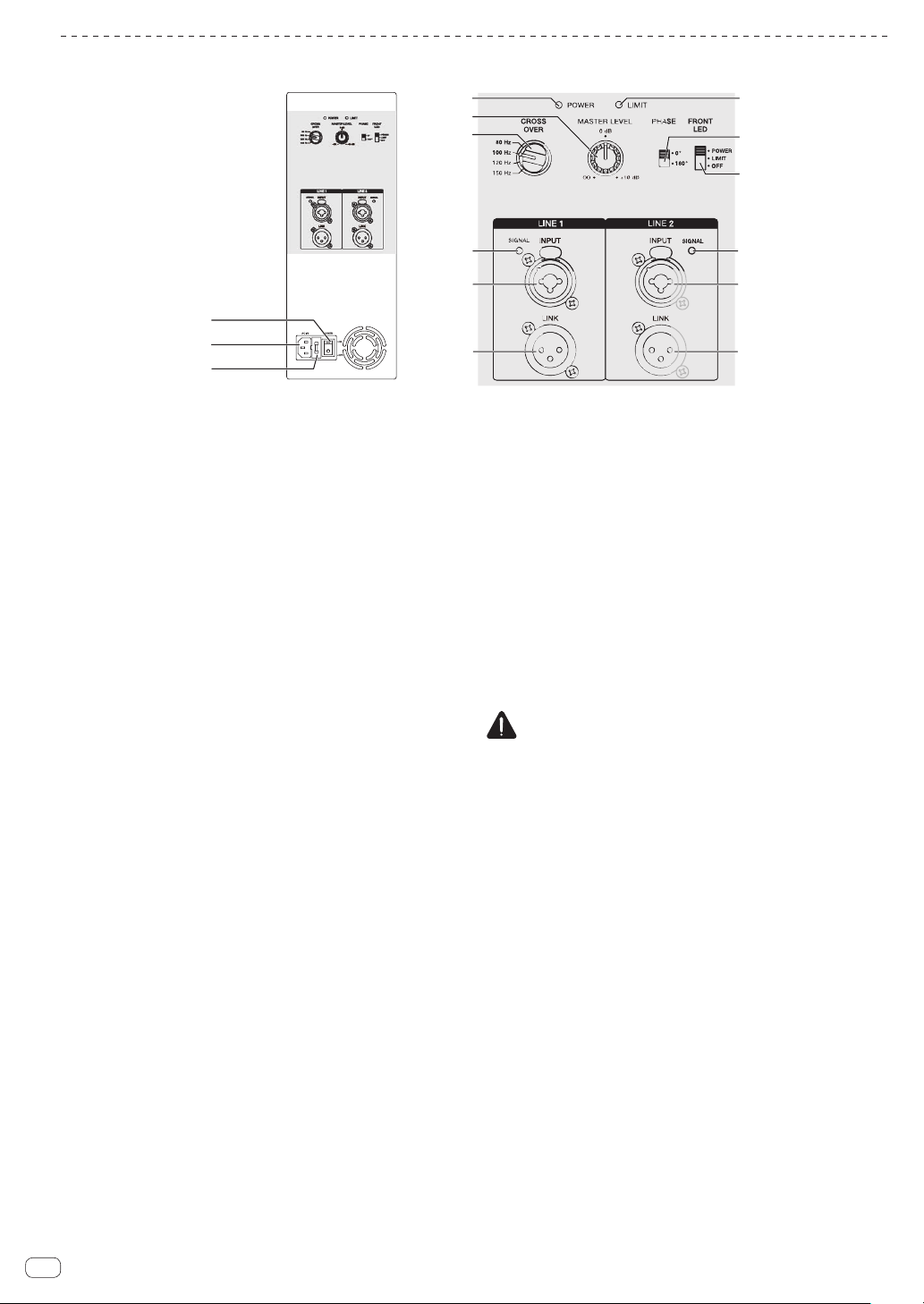
Rear Panel Facilities (Full-Range Models)
3
4
b
a
9
c
e
d
g
f
7
English
5
6
7
8
1
2
POWER switch
1
Turns this speaker’s power on and off.
AC IN
2
Connect the power cord to AC IN and then to the power outlet.
Fuse holder
3
Power indicator
4
Lights in blue when the power is turned on.
MASTER LEVEL
5
Adjusts the output level.
EQ MODE SELECT
6
Switches to four EQ modes (FLAT, BASS+, SPEECH, and
WEDGE). For details, see “EQ MODE Settings” on page 6.
INPUT LEVEL knob
7
Adjusts the input signal level.
GAIN knob (for MIC/LINE1 only)
8
Select the gain according to the output signal level of the device
to be connected. The selected gain is added to the signal input to
this unit.
• To input the signal of a line output device to this speaker,
select [0 dB] or [12 dB].
• To input a low-level output signal such as that of a
microphone to this unit, select [24 dB] or [36 dB].
SIGNAL indicator
9
A green indicator lights when an input signal is detected.
MIC/LINE1 and LINE2 INPUT
a
Both the XLR connector (balanced) and 1/4” TRS (balanced
type PHONO) are supported. The XLR connector consists of 1
“ground,” 2 “hot,” and 3 “cold.”
LINK
b
This is the XLR output connector (balanced). A signal input to
XLR INPUT will be output directly. (A signal input to AUX IN of
LINE2 will not be output.)
9
a
b
LIMIT indicator
c
Lights in red when the built-in limiter is activated or when the
input level is too high and the sound is distorted. When that
happens, lower the output level of the connected device or lower
the input level or master level of this unit.
EXT SUB MODE
d
Select [ ]for normal use.
Select [ ] when using a subwoofer.
FRONT LED
e
Selects the display setting of the FRONT LED indicator (white).
[POWER] Lights when the power is turned on.
[LIMIT] Lights when the limiter is activated.
[OFF] The FRONT LED does not light.
AUX IN
f
These are the RCA input connectors (unbalanced).
A stereo signal input to AUX IN is mixed to a monaural signal (not
output from the LINK connector).
MIX OUT
g
This is the XLR output connector (balanced). Mixes the signal
input to MIC/LINE1 and Line2 and then outputs it.
A signal adjusted in MIC GAIN and INPUT LEVEL is output.
CAUTION
When the FRONT LED setting is set to [OFF] and [LIMIT],
the speaker may appear the same as when the power plug
is disconnected from the power outlet depending on the
specification of the product, but the power is not shut off. If you
wish to shut off the power to the woofer completely, you must
disconnect the power plug from the power outlet. Install the
speaker near a power outlet so the power plug can easily be
accessed. Leaving the power plug inserted in a power outlet for a
long period of time may cause fire.
En
3
Rear Panel Facilities (Subwoofer Model)
3
4
a
c
b
9
8
7
1
2
5
6
7
8
9
POWER switch
1
Turns this speaker’s power on and off.
AC IN
2
Connect the power cord to AC IN and then to the power outlet.
Fuse holder
3
Power indicator
4
Lights in blue when the power is turned on.
MASTER LEVEL
5
Adjusts the output level.
CROSS OVER
6
Selects the cut-off frequency of the low pass filter for the
subwoofer from 80 Hz, 100 Hz, 120 Hz, and 150 Hz.
100 Hz is recommended when using the subwoofer with the
XPRS Series full-range speakers.
SIGNAL indicator
7
A green indicator lights when an input signal is detected.
LINE1 and LINE2 INPUT
8
Both the XLR connector (balanced) and 1/4” TRS (balanced
type PHONO) are supported. The XLR connector consists of 1
“ground,” 2 “hot,” and 3 “cold.”
LINK
9
This is the XLR output connector (balanced). A signal input to
XLR INPUT will be output directly.
LIMIT indicator
a
Lights in red when the built-in limiter is activated or when the
input level is too high and the sound is distorted. When that
happens, lower the output level of the connected device or lower
the input level or master level of this unit.
PHASE
b
Switches the polarity for the subwoofer. Select the one that
improves the playback of low frequencies when using the
subwoofer with other speakers.
FRONT LED
c
Selects the display setting of the FRONT LED indicator (white).
[POWER] Lights when the power is turned on.
[LIMIT] Lights when the limiter is activated.
[OFF] The FRONT LED does not light.
CAUTION
When the FRONT LED setting is set to [OFF] and [LIMIT],
the speaker may appear the same as when the power plug
is disconnected from the power outlet depending on the
specification of the product, but the power is not shut off. If you
wish to shut off the power to the woofer completely, you must
disconnect the power plug from the power outlet. Install the
speaker near a power outlet so the power plug can easily be
accessed. Leaving the power plug inserted in a power outlet for a
long period of time may cause fire.
En
4
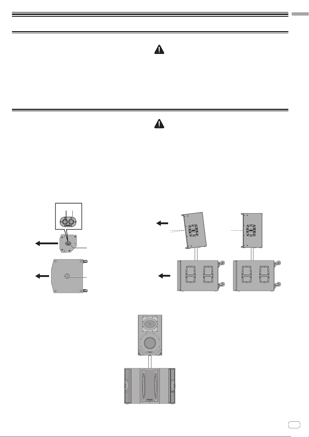
Installation and Connections
Multi-angle pole socket
Installation using a speaker pole
XPRS215S
How to Install
The playback sound of the speaker is subtly influenced by the conditions of the
listening room. Carefully consider the installation location before installing
the speaker so that it can be used in the best conditions. Pioneer DJ will not
be liable for any damages arising from the use of the speaker (including but
not limited to loss of business opportunities), regardless of the installation
method.
Use the handles on the top or the sides of the speaker when moving and
installing the speaker.
Installation Using a Speaker Pole
XPRS12/XPRS15
The full-range models of the XPRS series have a 35-mm-diameter multi-angle
pole socket on the bottom surface and can be installed downward at an angle
of 0° or 7° to the floor surface.
The subwoofer model of the XPRS series has an M20 screw-in pole socket on
the top surface and the pole can be secured firmly.
The combinations shown in the following figures are recommended for the
XPRS series. Use with a combination other than those may result in the
speakers toppling over, causing damage or injury. To use a speaker pole,
check the cautions on the right and perform the installation safely.
CAUTION
When standing or laying the XPRS115S, XPRS215S, take care that the
!
casters do not slip and cause an injury.
To promote proper cooling, please assure that sufficient space
!
is preserved between the speakers and nearby walls or other
components (minimum 30 cm or more above, behind, and to right
and left sides of each speaker). Leaving insufficient space between
the speaker and walls or other components may lead to rising interior
temperatures, leading to malfunction or damage.
CAUTION
At least two persons should together lift the speaker to install. Give
!
sufficient consideration to safety when performing the work.
For the speaker pole, use a 35-mm-diameter, one-side M20 screw-in
!
speaker pole. Use a commercially-available product with a length
of 900 mm or less. Pioneer DJ will not be liable for any damages
(including but not limited to loss of business opportunities) arising
from the use of a speaker pole other than specified.
Install the subwoofer in a stable location and secure the speaker pole
!
firmly.
Ensure that there is no danger of toppling.
!
Cables should be taped or tied together with cable ties so as to avoid
!
the danger of tripping on the cables and toppling the speaker.
English
Front
7° 0°
35-mm-diameter
pole socket
M20 screw-in
pole socket
Front
XPRS12, XPRS15
7°
0°
En
5
 Loading...