

Page 1
SATELLITE SUBWOOFER
ORDER NO.
RRV2346
SPEAKER SYSTEM
S-F10-LRW XMD/UC
This product is component of system.
Component
STEREO CD TUNER
STEREO POWER AMPLIFIER
SPEAKER SYSTEM
65S
This service manual is intended for qualified service technicians; it is not meant
for the casual do-it-yourselfer. Qualified technicians have the necessary test
equipment and tools, and have been trained to properly and safely repair complex
products such as those covered by this manual.
Improperly performed repairs can adversely affect the safety and reliability
of the product and may void the warranty. If you are not qualified to perform the
repair of this product properly and safely, you should not risk trying to do so and
refer the repair to a qualified service technician.
System
XC-F10
M-F10
S-F10-LRW
S-F10-LR
S-F10-W
Service Manual
RRV2341
RRV2321
RRV2346
WARNING
This product contains lead in solder and certain electrical parts contain chemicals
which are known to the state of California to cause cancer, birth defects or other
reproductive harm.
Health & Safety Code Section 25249.6 – Proposition 65
FOR PRECAUTION OF
REASSEMBLY AND DISASSEMBLY
[ S-F10-W ] ( Subwoofer )
The woofer is attached to the back board by 4 external screws.
To detach it, unfasten those screws. When attaching it, face its
terminal downward.
The cosmetic baffle is attached to the baffle by press-fitting.
To detach it, pry it open by inserting a flat blade screwdriver
into the lower side.
The input terminal is attached to the back board by press-fitting. To detach it, pry it open by inserting a flat blade screwdriver.
PIONEER CORPORATION 4-1, Meguro 1-chome, Meguro-ku, Tokyo 153-8654, Japan
PIONEER ELECTRONICS SERVICE, INC. P.O. Box 1760, Long Beach, CA 90801-1760, U.S.A.
PIONEER EUROPE NV Haven 1087, Keetberglaan 1, 9120 Melsele, Belgium
PIONEER ELECTRONICS ASIACENTRE PTE. LTD. 253 Alexandra Road, #04-01, Singapore 159936
PIONEER CORPORATION 2000
[ S-F10-LR ] ( Satellite Speaker )
The grille is attached to the cabinet by catches.
To detach it, pull it toword you.
The speaker element is attached to the baffle by 2 external
screws. To detach it, first remove the stand. The stand is attached the cabinet by 3 external screws.To detached it unfasten
those screws. Next remove the cabinet. The cabinet is attached
the baffle by 6 external screws. To detached it unfasten those
screws. Then remove the speaker element.When attaching it,
face its terminal upward.
The input terminal is attached to the cabinet by 2 internal
screws. To detach it, first remove the cabinet. Then remove the
input terminal.
Remarks
This service manual
(2 pieces)
(1 piece)
T-ZZM AUG. 2000 Printed in Japan
Page 2
S-F10-LRW
PARTS LIST
NOTES:
Mark No. Description Part No.
NSP Speaker System (Satellite) S-F10-LR/XMD/UC
NSP Speaker System (Sub Woofer) S-F10-W/XMD/UC
For Packing
NSP Binder KNK-431
NSP Grille Cloth SAS1487
NSP Grille Frame SMH1013
NSP Stand ASSY SNX1142
Parts marked by "NSP" are generally unavailable because they are not in our Master Spare Parts List.
The mark found on some component parts indicates the importance of the safety factor of the part.
Therefore, when replacing, be sure to use parts of identical designation.
Speaker Cable ASSY SDS1091
Speaker Cord ( for Sub Woofer ) SDF1085
Speaker Cord ( for Satellite ) SDS1092
Polyethylene Bag S1 SHL1264
Grille (Blue) SMG1703
Non-Skid Pad SEC1474
Stand SNK2481
For S-F10-LR
Mark No. Description Part No.
Grille (Gray) SMG1692
NSP Grille Cloth SAS1479
NSP Grille Frame SMH1013
NSP Inner Baffle SNK2471
NSP Cabinet SNK2472
Stand SNK2480
NSP Label Back SAN2875
Connect Cord SDD1274
NSP Damper SEC1490
NSP Acoustic Absorbent (100 x 75) SMV1992
NSP Acoustic Absorbent (120 x 25) SMV2007
Speaker B70AC50-51F
Screw ( for Input Terminal ) BPZ30P080FZK
Screw ( S t a n d - Cabinet, Cabinet-Baffle ) BPZ40P120FZK
Top Protector SHA2231
Middle Protector SHA2232
Bottom Protector SHA2233
Packing Case SHG2307
Polyethylene Bag S5 (for Sub Woofer) SHL1248
Polyethylene Bag S2 (for Stand) SHL1269
Polyethylene Bag S2 (for Satellite) SHL1270
Polyethylene Bag S1 (for Grille) SHL1271
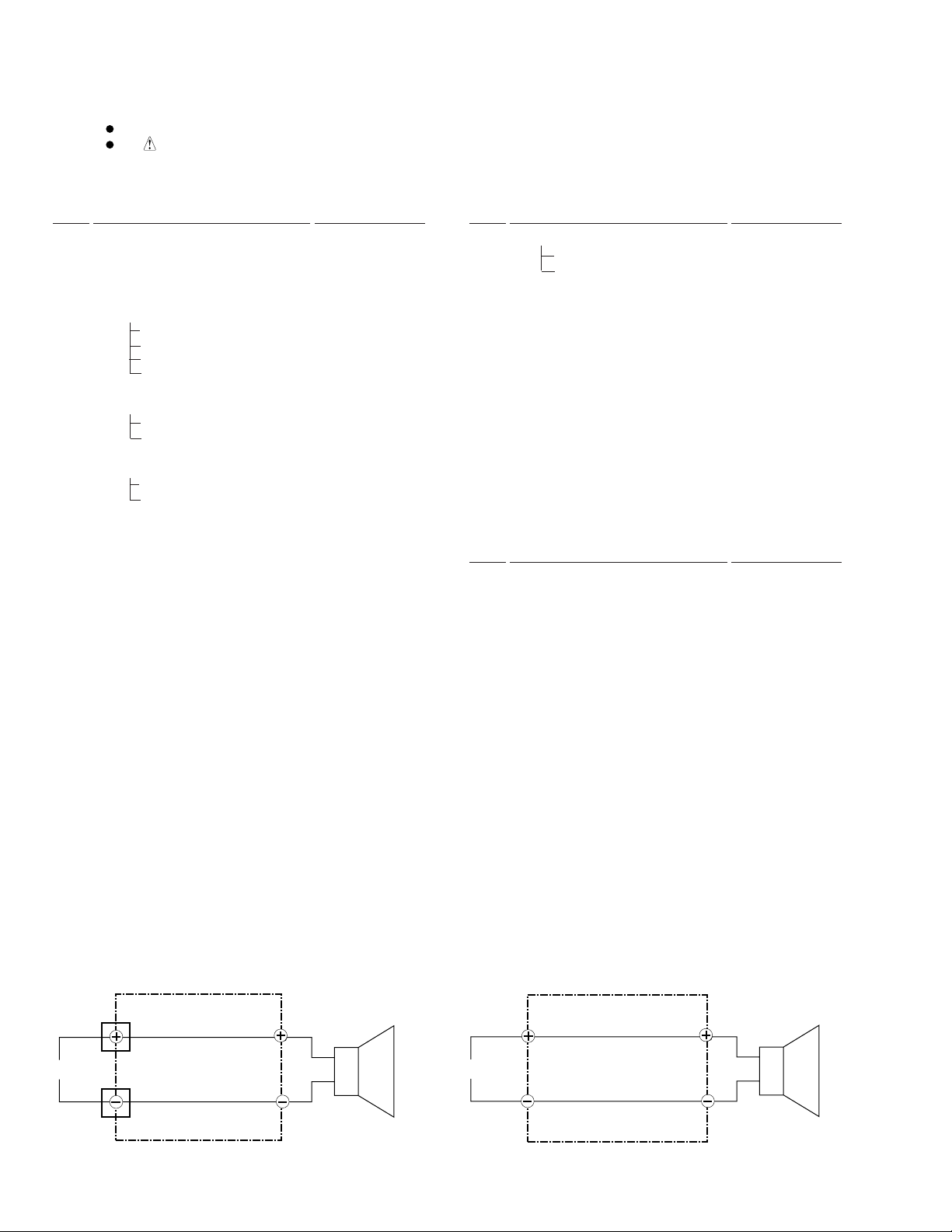
SCHEMATIC DIAGRAM
Satellite
For S-F10-W
Mark No. Description Part No.
NSP Cabinet SMM1922
NSP Label Back SAN2876
Connect Cord SDD1273
Non-Skid Pad SEC1473
NSP Packing (250 x 6) SEC1475
NSP Packing (125 x6) SEC1476
NSP Packing (for Tube) SEC1505
Input Terminal SKX1060
NSP Cosmetic Duct SMR1318
NSP Paper Tube 50 SMR1321
NSP Acoustic Absorbent ( for Bottom) SMV1984
NSP Acoustic Absorbent ( for Back ) SMV2009
NSP Cosmetic Baffle (Gray) SNK2477
NSP Cosmetic Baffle (Silver) SNK2478
Speaker A14ER75-52C
Screw ( for Speaker ) BYC40P200FZB
Screw ( for Cosmetic Baffle) BPZ40P120FZK
Sub Woofer
Connect Cord (SDD1273)Connect Cord (SDD1274)
RED
INPUT
BLACK
2
BLUE
WHITE
Full-Range
RED
Woofer
INPUT
BLACK
Page 3

PRODUCT APPEARANCE
S-F10-LRW
SATELLITE
130
3
245
Part name
Cabinet
1
Inner
2
3
4
5
6
8
9
10 9
Baffle
Grille
Speaker
Acoustic Absorbent
Acoustic Absorbent
Label Back 71
Stand
Screw
Screw
Num.No. Remarks Part name Num.No. Remarks
1
1
1
1
1
SMV1992
2
SMV2007
1
2
BPZ30P080FZK
BPZ40P120FZK
64
6
1
2
5
7
10
8
4
Connect Cord
12
13
14
15
16
17
18
19
20
10
6
9
11
111
SDD1274
SUBWOOFER
190
8
9
1
282
6
11
3
12
Part name
Cabinet
1
2
Speaker
3
Cosmetic Duct
4
Connection Cord
5
Acoustic Absorbent
6
Acoustic Absorbent
Input Terminal71
8
Cosmetic Baffle
9
Cosmetic Baffle
10 4
Screw
Num.No. Remarks Part name Num.No. Remarks
14
1
1
1
1
1
SMV1984
1
SMV2009
1
SNK2478
1
SNK2477
BYC40P200FZB
11
253
5
11
12
13
14
15
16
17
18
19
20
226
4
15
Staple
Non Skid Pad
Label Back
Screw
Paper Tube 50
2
10
6
4
1
6
1
13
7
80/8 BEA
BPZ40P120FZK
3
 Loading...