

Pioneer SA-3800 Service manual
SPEAKER SYSTEM
S-A3800 XJI/UC
This product is component of system.
ORDER NO.
RRV2353
Component
COMPACT MINI COMPONENT
STEREO CD CASSETTE DECK RECIEVER
SPEAKER SYSTEM This service manual
65S
This service manual is intended for qualified service technicians; it is not meant
for the casual do-it-yourselfer. Qualified technicians have the necessary test
equipment and tools, and have been trained to properly and safely repair complex
products such as those covered by this manual.
Improperly performed repairs can adversely affect the safety and reliability
of the product and may void the warranty. If you are not qualified to perform the
repair of this product properly and safely, you should not risk trying to do so and
refer the repair to a qualified service technician.
WARNING
This product contains lead in solder and certain electrical parts contain chemicals
which are known to the state of California to cause cancer, birth defects or other
reproductive harm.
Health & Safety Code Section 25249.6 – Proposition 65
System Service Manual
X-A3800
XR-A3800
S-A3800
RRV2356
RRV2353
FOR PRECAUTION OF
REASSEMBLY AND DISASSEMBLY
The cosmetic baffle assy is attached to the cabinet by 4 external
hexagon socket screws. To detach the cosmetic baffle assy,
loosen these screws by the hexagon screw driver. Then carefully disconnect the wires of the woofer and mid-range
mounted on the cosmetic baffle assy. To attach the cosmetic
baffle assy, replace it on the cabinet correctly and secure with 4
screws.
The woofer is attached to the cosmetic baffle assy by 4 internal
screws. To detach it, unfasten these screws. When attaching it,
face its terminal downward.
The mid-range is attached to the cosmetic baffle assy by 2 internal screws. To detach the mid-range, loosen these screws. Then
carefully disconnect the wires of the tweeter mounted on the
cosmetic baffle assy by adhesion. To attach the mid-range, replace it on the cosmetic baffle assy correctly and secure with 2
screws.
Remarks
When exchange the tweeter, do it with the cosmetic baffle assy.
PIONEER CORPORATION 4-1, Meguro 1-chome, Meguro-ku, Tokyo 153-8654, Japan
PIONEER ELECTRONICS SERVICE, INC. P.O. Box 1760, Long Beach, CA 90801-1760, U.S.A.
PIONEER EUROPE NV Haven 1087, Keetberglaan 1, 9120 Melsele, Belgium
PIONEER ELECTRONICS ASIACENTRE PTE. LTD. 253 Alexandra Road, #04-01, Singapore 159936
PIONEER CORPORATION 2000
T-ZZM JULY 2000 Printed in Japan
S-A3800
PARTS LIST
NOTES:
Mark No. Description Part No.
NSP Cabinet SMM1889
NSP Stamped Model Label (L) SME3013
NSP Model Label (L) SAN2811
NSP Stamped Model Label (R) SME3014
NSP Model Label (R) SAN2812
Parts marked by "NSP" are generally unavailable because they are not in our Master Spare Parts List.
The mark found on some component parts indicates the importance of the safety factor of the part.
Therefore, when replacing, be sure to use parts of identical designation.
Network ASSY SWN1618
Gasket (for Baffle wide) SEC1359
Non Skid Pad SEC1374
Gasket (for Baffle height) SEC1380
For Packing
Mark No. Description Part No.
Top Protector SHA2217
Bottom Protector SHA2218
Packing Case SHG2259
NSP Polyethylene Bag S5 SHL1212
NSP Duct (L) SMR1315
Cosmetic Baffle ASSY (L) SXB1410
NSP Duct (R) SMR1316
NSP Punching Net SNC1183
NSP Cosmetic Baffle (L) SNK2466
Diaphragm ASSY 20 SXE1092
NSP Ceramic Tweeter SCA1017
NSP Terminal (Red) SKF1034
NSP Terminal (Black) SKF1035
Cosmetic Baffle ASSY (R) SXB1411
NSP Duct (L) SMR1315
NSP Duct (R) SMR1316
NSP Punching Net SNC1183
NSP Cosmetic Baffle (R) SNK2467
Diaphragm ASSY 20 SXE1092
NSP Ceramic Tweeter SCA1017
NSP Terminal (Red) SKF1034
NSP Terminal (Black) SKF1035
Speaker (Woofer) A14LC83-54D
Speaker (Mid-range) E52AP39-58D
Screw (for Mid-range) BPZ40P080FMC
Screw (for Woofer) BPZ40P100FMC
Tapping Screw (for Cosmetic Baffle) SBA1162
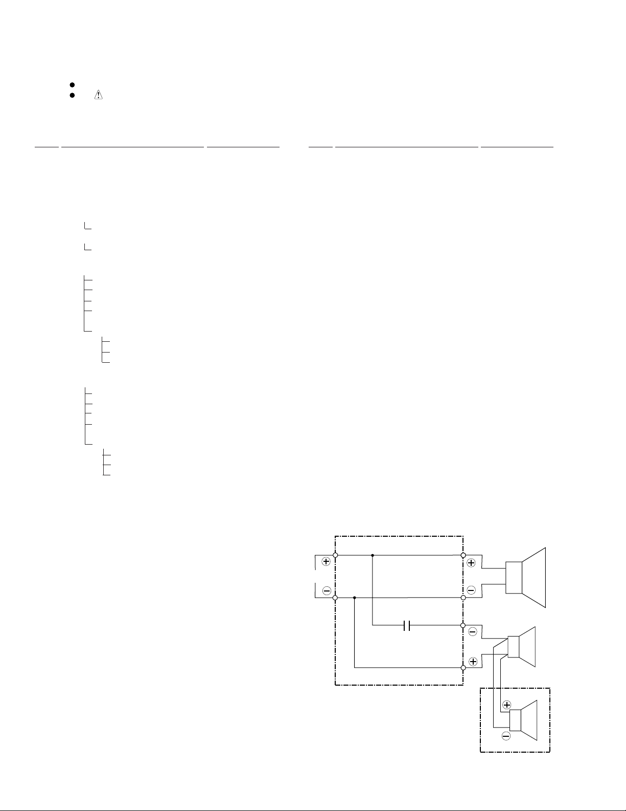
SCHEMATIC DIAGRAM
Network ASSY (SWN1618)
Red
Red
Woofer
I N
Black
2.2µF
Black
White
Green
Midrange
Tweeter
Red
Diaphragm ASSY 20
(In Cosmetic Baffle ASSY)
2
Black
 Loading...