

Page 1
COLOR BRIGHT MONITOR
ENTER
MENU
SETUP
5
2
3
RETURNTOP MENU
∞
¡ ¢
4 1
3
7
PUSH
CL0SE
• PDV-LC20
8
OFF ON
POTABLE DVD PLAYER
PDV-LC20
PDV-20
BATTERY PACK
ORDER NO.
RRV2383
PDV-BT20
PDV-BT25
Z/E
Z/E
THIS MANUAL IS APPLICABLE TO THE FOLLOWING MODEL(S) AND TYPE(S).
Type
ZU/CA – AC120V Adapter or Battery pack 1
ZY AC100V-240V Adapter or Battery pack 2
ZL AC100V-240V Adapter or Battery pack 3
PDV-LC20 PDV-20
• This service manual should be used
together with the following manual (s) :
Model No. Order No. Remarks
PDV-LC20 RRV2401
CONTENTS
1. SAFETY INFORMATION
2. EXPLODED VIEWS AND PARTS LIST
3. BLOCK DIAGRAM AND SCHEMATIC DIAGRAM
4. PCB CONNECTION DIAGRAM
5. PCB PARTS LIST
6. ADJUSTMENT
Model
Confirmation / adjustment of a LCD
monitor part.
.......................................
...........................
................................................
.....................................................
Power Requirement Region No. Remarks
.................
...
10
30
35
39
Option
• Battery pack
(PDV-BT20 / PDV-BT25)
(PDV-BT20 is supplied with PDV-LC20)
* These exchange a product in service.
2
4
7. GENERAL INFORMATION
7.1 DIAGNOSIS
7.1.1 DISASSEMBLY
7.1.2 TROUBLE SHOOTING
7.2 IC
8. PANEL FACILITIES AND SPECIFICATIONS
..................................................................
..................................................
................................
....................................
........................
....
40
40
40
43
44
55
PIONEER CORPORATION 4-1, Meguro 1-chome, Meguro-ku, Tokyo 153-8654, Japan
PIONEER ELECTRONICS SERVICE, INC. P.O. Box 1760, Long Beach, CA 90801-1760, U.S.A.
PIONEER EUROPE NV Haven 1087, Keetberglaan 1, 9120 Melsele, Belgium
PIONEER ELECTRONICS ASIACENTRE PTE. LTD. 253 Alexandra Road, #04-01, Singapore 159936
c
PIONEER CORPORATION 2000
T – IZE SEPT. 2000 Printed in Japan
Page 2
PDV-LC20, PDV-20
1. SAFETY INFORMATION
This service manual is intended for qualified service technicians ; it is not meant for the casual do-ityourselfer. Qualified technicians have the necessary test equipment and tools, and have been trained
to properly and safely repair complex products such as those covered by this manual.
Improperly performed repairs can adversely affect the safety and reliability of the product and may
void the warranty. If you are not qualified to perform the repair of this product properly and safely, you
should not risk trying to do so and refer the repair to a qualified service technician.
WARNING
This product contains lead in solder and certain electrical parts contain chemicals which are known to the state of California to cause
cancer, birth defects or other reproductive harm.
Health & Safety Code Section 25249.6 – Proposition 65
NOTICE
(FOR CANADIAN MODEL ONLY)
Fuse symbols (fast operating fuse) and/or (slow operating fuse) on PCB indicate that replacement parts must
be of identical designation.
REMARQUE
(POUR MODÈLE CANADIEN SEULEMENT)
Les symboles de fusible (fusible de type rapide) et/ou (fusible de type lent) sur CCI indiquent que les pièces
de remplacement doivent avoir la même désignation.
(FOR USA MODEL ONLY)
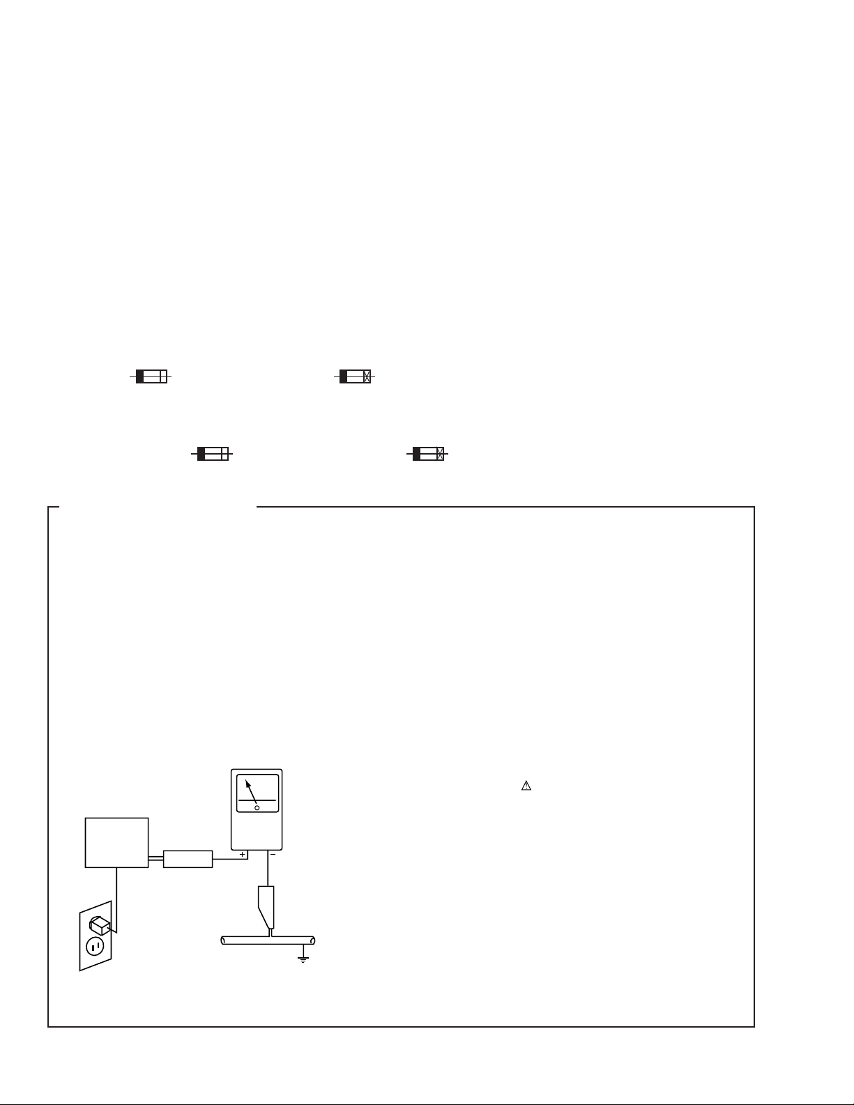
1. SAFETY PRECAUTIONS
The following check should be performed for the
continued protection of the customer and service
technician.
LEAKAGE CURRENT CHECK
Measure leakage current to a known earth ground (water
pipe, conduit, etc.) by connecting a leakage current tester
such as Simpson Model 229-2 or equivalent between the
earth ground and all exposed metal parts of the appliance
(input/output terminals, screwheads, metal overlays, control
shaft, etc.). Plug the AC line cord of the appliance directly
into a 120V AC 60Hz outlet and turn the AC power switch
on. Any current measured must not exceed 0.5mA.
Reading should
not be above
0.5mA
Earth
ground
Device
under
test
Also test with
plug reversed
(Using AC adapter
plug as required)
Leakage
current
tester
Test all
exposed metal
surfaces
ANY MEASUREMENTS NOT WITHIN THE LIMITS
OUTLINED ABOVE ARE INDICATIVE OF A POTENTIAL
SHOCK HAZARD AND MUST BE CORRECTED BEFORE
RETURNING THE APPLIANCE TO THE CUSTOMER.
2. PRODUCT SAFETY NOTICE
Many electrical and mechanical parts in the appliance
have special safety related characteristics. These are
often not evident from visual inspection nor the protection
afforded by them necessarily can be obtained by using
replacement components rated for voltage, wattage, etc.
Replacement parts which have these special safety
characteristics are identified in this Service Manual.
Electrical components having such features are identified
by marking with a
in this Service Manual.
The use of a substitute replacement component which does
not have the same safety characteristics as the PIONEER
recommended replacement one, shown in the parts list in
this Service Manual, may create shock, fire, or other hazards.
Product Safety is continuously under review and new
instructions are issued from time to time. For the latest
information, always consult the current PIONEER Service
Manual. A subscription to, or additional copies of, PIONEER
Service Manual may be obtained at a nominal charge from
PIONEER.
on the schematics and on the parts list
AC Leakage Test
2
Page 3
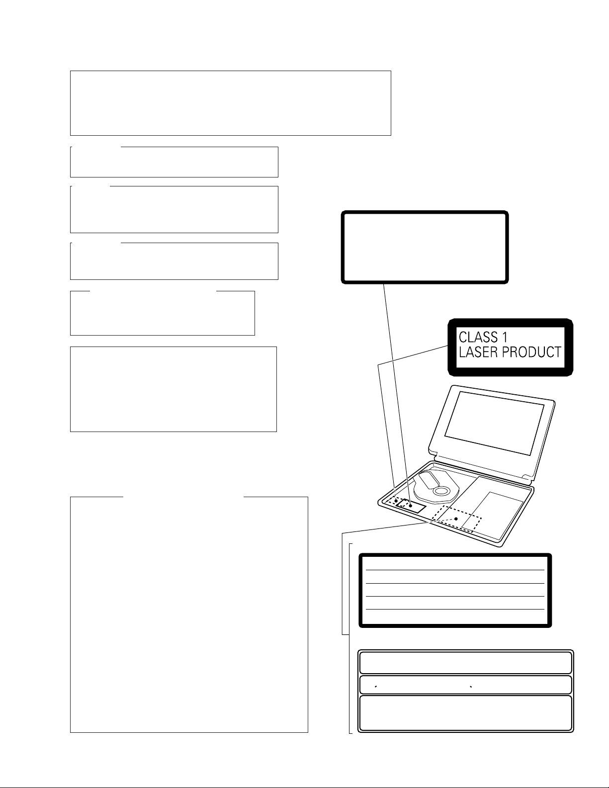
The AEL(accessible emission level) of the laser power output is less than CLASS 1
LABEL CHECK
ZU/CA Type Only
ZU/CA Type Only
ZY Type Only
ZY and ZL Types Only
VRW1867
VRW1815
VRW1860
VRW-328
CERTIFICATION
THIS PRODUCT COMPLIES WITH DHHS RULES 21CFR, SUBCHAPTER J,
PART 1040 AT DATE OF MANUFACTURE.
This Class B digital apparatus complies with Canadian ICES-003. Cet appareil
numerique de la classe B est comforme a la norme NMB-003 du Canada.
THIS DEVICE COMPLIES WITH PART 15 OF THE FCC RULES.
OPERATION IS SUBJECT TO THE FOLLOWING TWO CONDITIONS :
(1)THIS DEVICE MAY NOT CAUSE HARMFUL INTERFERENCE, AND
(2)THIS DEVICE MUST ACCEPT ANY INTERFERENCE RECEIVED, INCLUDING
INTERFERENCE THAT MAY CAUSE UNDESIRED OPERATION.
LASER RADIATION WHEN OPEN,
AVOID LONG-TERM VIEWING OF
DIRECT LASER RADIATION.
< VRW1815 >
CAUTION
CAUTION :
VORSICHT :
ADVARSEL :
VARNING :
VARO! :
VISIBLE AND INVISIBLE LASER RADIATION WHEN OPEN.
AVOID EXPOSURE TO BEAM.
SICHTBARE UND UNSICHTBARE LASERSTRAHLUNG, WENN
ABDECKUNG GEÖFFNET NICHT DEM STRAHL AUSSETZEN!
SYNLIG OG USYNLIG LASERSTRÅLING VED ÅBNING UNDGÅ
UDSÆTTELSE FOR STRÀLING.
SYNLIG OCH OSYNLIG LASERSTRÅLNING NÄR DENNA DEL ÄR
ÖPPNAD BETRAKTA EJ STRÅLEN.
AVATTAESSA ALTISTUT NÄKYVÄ JA NÄKYMÄTTÖMÄLLE
LASERSATEIL YLLE. ÄLÄ KATSO SÄTEESEN.
VRW1860
VRW-328
but the lasear component is capable of emitting radiation exceeding the limit for
CLASS 1.
A specially instructed person should do servicing operation of the apparatus.
CAUTION :
LASER RADIATION WHEN OPEN, AVOID LONG-TERM
VIEWING OF DIRECT LASER RADIATION.
CAUTION :
USE OF CONTROLS OR ADJUSTMENTS OR PERFORMANCE OF PROCEDURES OTHER THAN THOSE
SPECIFIED HEREIN MAY RESULT IN HAZARDOUS
RADIATION EXPOSURE.
CAUTION :
TO PREVENT RISK OF ELECTRIC SHOCK AND LASER
EXPOSURE, DISCONNECT THE AC ADAPTER OR THE
BATTERY BEFORE REMOVE SCREWS.
LASER DIODE CHARACTERISTICS
FOR DVD : MAXIMUM OUTPUT POWER : 3.2 mW
FOR CD : MAXIMUM OUTPUT POWER : 3.3 mW
WAVELENGTH : 650 nm
WAVELENGTH : 780 nm
PDV-LC20, PDV-20
WARNING!
CAUTION
Danger of explosion if battery is incorrectly replaced.
Replaced only with the same or equivalent type
recommended by the manufacture.
Discord used batteries according to the manufacture's
instructions.
1. Laser Interlock Mechanism
If the switches to detect door-open state (S603, S605: DISC
OPEN DET) are open, the laser interlock mechanism operates
and shuts down the power source (Q100) to the laser diode drive
circuit. The system microcomputer detects this condition and
does not issue the Laser On command.
If Q100 is defective, accompanying a short-circuit between the
emitter and the collector, the system microcomputer judges this
status as the door-open state, and it does not issue the Laser
On command as long as Q611 is not defective, even if S603 and
S605 are open.
Therefore, the laser does not light unless S603 and S605 are
intentionally short-circuited in door-open state.
To light the laser in Test mode, short-circuit S603 and S605.
Hold S603 and S605 in the depressed position from the top, as
they are push switch.
2. NEVER directly look at the objective lens from a short distance
when lighting the laser by short-circuiting S603 and S605 in dooropen state.
Additional Laser Caution
3
Page 4
PDV-LC20, PDV-20
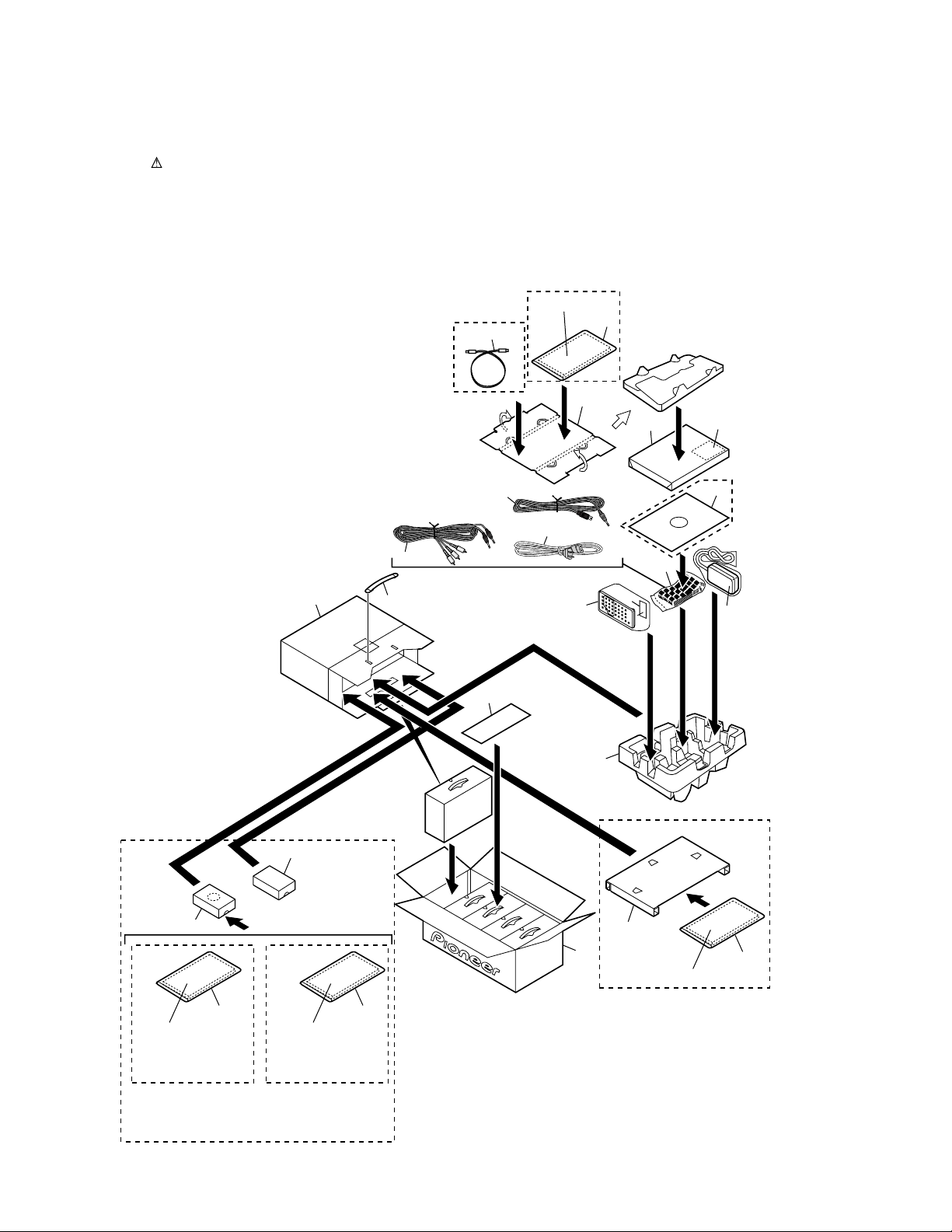
2. EXPLODED VIEWS AND PARTS LIST
NOTES:• Parts marked by "NSP" are generally unavailable because they are not in our Master Spare Parts List.
2.1 PACKING
The mark found on some component parts indicates the importance of the safety factor of the part.
•
Therefore, when replacing, be sure to use parts of identical designation.
PDV-20/ZL Only
ZY Type
Only
21
11, 29
7
10
19
Player
5
20
30
PDV-20
Only
PDV-LC20 Only
15
11, 14
(PDV-LC20/ZU/CA)
11, 29
(PDV-LC20/ZL)
PDV-LC20/ZU/CA
and
PDV-LC20/ZL
Only
7
12
6
11, 14, 22-27
PDV-LC20/ZY
Only
28
13
3
4
8
18
1
17
PDV-20/ZY
Only
7
9
2
15
28
11, 14, 22-27
4
Page 5
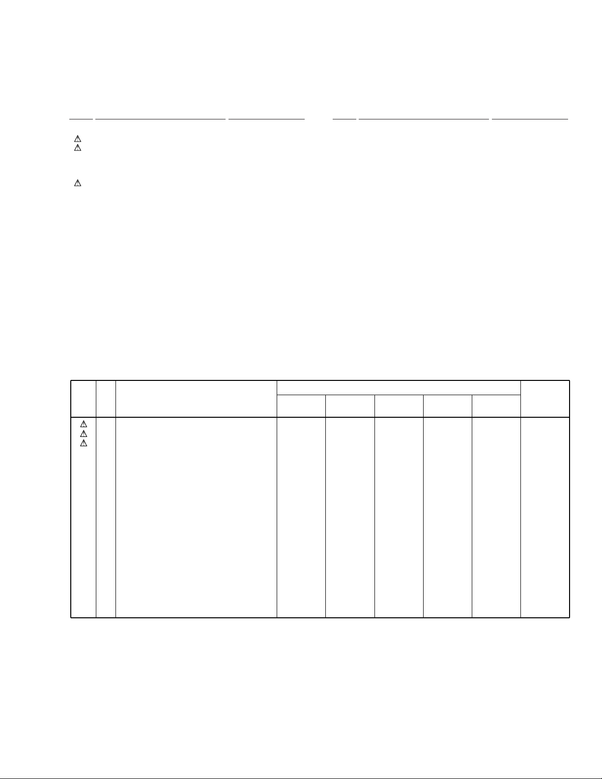
(1) PACKING PARTS LIST
PDV-LC20, PDV-20
Mark No. Description Part No.
1 Tray VHB1069
2 AC Adapter See Contrust table (2)
3 Power Cable See Contrust table (2)
4 AV Cable (L = 1.5m) VDE1066
5 S Video Cable (L = 1.5m) VDE1067
6 Battery Pack See Contrust table (2)
7 Polyethylene Bag B5 VHL1051
8 Remote Control Unit VXX2724
9 Battery Cover VNK4730
10 Top Plate VHC1045
11 Opearating Instructions VRB1258
(English)
12 Packing Case See Contrust table (2)
13 Handle VEE1006
NSP 14 Warranty Card See Contrust table (2)
15 Manual Holder See Contrust table (2)
Mark No. Description Part No.
16 • • • • •
17 Master Carton See Contrust table (2)
18 Mat Plate VHC1048
19 Mirror Mat DHL1050
20 Name Plate Label See Contrust table (2)
21 Optical Cable See Contrust table (2)
22 Operating Instructions (French) See Contrust table (2)
23 Operating Instructions (Italy) See Contrust table (2)
24 Operating Instructions (German)See Contrust table (2)
25 Operating Instructions (Dutch) See Contrust table (2)
26 Operating Instructions See Contrust table (2)
(Swedish)
27 Operating Instructions (Spanish)See Contrust table (2)
28 Polyethylene Bag See Contrust table (2)
(0.03 × 230 × 340)
29 Operating Instructions (Chinese)See Contrust table (2)
30 Middle Plate See Contrust table (2)
(2) CONTRAST TABLE
PDV-LC20/ZU/CA, ZY, ZL, PDV-20/ZY and ZL are constructed the same except for the following :
Part No.
Mark No. Symbol and Description
2
AC Adapeter
3
Power Cable
6
Battery Pack
12
NSP
Packing Case
14
Warranty Card
PDV-LC20
/ZU/CA
VWX1228
RDG1034
VEM1028
VHG1987
ARY7045
PDV-LC20
/ZY
VWX1228
ADG1127
VEM1028
VHG1976
ARY7022
PDV-LC20
/ZL
VWX1229
ADG1127
VEM1028
VHG2018
Not used
PDV-20
/ZY
VWX1228
ADG1127
Not used
VHG1991
ARY7022
PDV-20
/ZL
VWX1229
ADG1127
Not used
VHG2020
Not used
Remarks
15
Manual Holder
17
Master Carton
20
Name Plate Label
21
Optical Cable
22
Operating Instructions (French)
23
Operating Instructions (Italy)
24
Operating Instructions (German)
25
Operating Instructions (Datch)
26
Operating Instructions (Swedish)
27
Operating Instructions (Spanish)
28
Polyethylene Bag (0.03 × 230 × 340)
29
Operating Instructions (Chinese)
30
Middle Plate
VHC1074
VHG1986
VRW1859
Not used
Not used
Not used
Not used
Not used
Not used
Not used
Not used
Not used
Not used
VHC1074
VHG1975
VRW1858
VDE1062
VRD1120
VRD1121
VRD1122
VRD1123
VRD1124
VRD1125
Z21-038
Not used
Not used
VHC1074
VHG2017
VRW1858
Not used
Not used
Not used
Not used
Not used
Not used
Not used
Not used
VRD1126
Not used
VHC1062
VHG1990
VRW1858
VDE1062
VRD1120
VRD1121
VRD1122
VRD1123
VRD1124
VRD1125
Z21-038
Not used
VHC1076
Not used
VHG2019
VRW1858
Not used
Not used
Not used
Not used
Not used
Not used
Not used
Not used
VRD1126
VHC1076
5
Page 6
PDV-LC20, PDV-20
3.2 MAIN SECTION
PDV-LC20
Only
24
6
8
18
16
17
15
PDV-LC20
Only
32
ZU/CA Type
Only
Refer to
"2.3 LCD MONITOR SECTION".
24
19
20 or 21
26
28
27
ZU/CA Type
Only
13
7
12
PDV-20
Only
4
Except
ZU/CA
Type
35
30
29
B
2
7
1
7
A
33
9
24
ZY Type
Only
6
PDV-LC20
Only
34
31 (ZU/CA Type)
or
36 (ZY and ZL Types)
22
10
25
11
14
23
Page 7
PDV-LC20, PDV-20
(1) MAIN SECTION PARTS LIST
Mark No. Description Part No. Mark No. Description Part No.
1 PDVDM Assy See Contrust table (2)
2 PDVDS Assy See Contrust table (2)
3 • • • • •
4 Traverse Mechanism Assy VXX2735
5 • • • • •
6 Rear Cover See Contrust table (2)
7 Float Rubber VEB1303
8 Switch Cap See Contrust table (2)
9 Heat Sink VNH1065
10 IR Filter VNK4709
11 LED Lens VNK4710
12 Open Knob VNK4711
13 Stopper Spring VBH1315
14 Connector Cover See Contrust table (2)
15 Caution Label VRW1847
16 Cover Spring VBH1332
17 Body See Contrust table (2)
18 Top Cover See Contrust table (2)
19 Cover Lens See Contrust table (2)
20 Logo Plate See Contrust table (2)
NSP 34 Caution Label (F) See Contrust table (2)
21 Display Lens See Contrust table (2)
22 Leg Rubber VEB1313
23 Screw VBA1062
24 Screw VBA1061
25 Chassis See Contrust table (2)
26 Operation Button A See Contrust table (2)
27 Operation Button B VNK4707
28 Cursol Key See Contrust table (2)
29 Sheet See Contrust table (2)
30 Display LCD Sheet See Contrust table (2)
31 Label See Contrust table (2)
32 65 Label See Contrust table (2)
33 NP Knob See Contrust table (2)
35 Label (Service) See Contrust table (2)
36 Caution Label See Contrust table (2)
(2) CONTRAST TABLE
PDV-LC20/ZU/CA, ZY, ZL, PDV-20/ZY and ZL are constructed the same except for the following :
Part No.
Mark No. Symbol and Description
1
PDVDM Assy
2
PDVDS Assy
6
Rear Cover
8
Switch Cap
14
Connector Cover
PDV-LC20
/ZU/CA
VWS1456
VWG2254
VNK4713
VNK4481
VNK4712
PDV-LC20
/ZY
VWS1457
VWG2255
VNK4713
VNK4481
VNK4712
PDV-LC20
/ZL
VWS1457
VWG2256
VNK4713
VNK4481
VNK4712
PDV-20
/ZY
VWS1461
VWG2259
Not used
Not used
VNK4736
PDV-20
/ZL
VWS1461
VWG2260
Not used
Not used
VNK4736
Remarks
NSP
17
Body
18
Top Cover
19
Cover Lens
20
Logo Plate
21
Display Lens
25
Chassis
26
Operation Button A
28
Cursol Key
29
Sheet L
29
Sheet S
30
Display LCD Sheet
31
Label
32
65 Label
33
NP Knob
34
Caution Label (F)
35
Label (Service)
36
Caution Label
VNK4738
VNK4705
VAH1368
VAH1358
Not used
VNK4731
VNK4706
VNK4708
VEC2186
Not used
Not used
VRW1867
ARW7050
Not used
Not used
VRW1815
Not used
VNK4738
VNK4750
VAH1368
VAH1358
Not used
VNK4731
VNK4706
VNK4708
VEC2186
Not used
Not used
Not used
Not used
VNK4719
VRW-328
Not used
VRW1860
VNK4738
VNK4750
VAH1368
VAH1358
Not used
VNK4731
VNK4706
VNK4708
VEC2186
Not used
Not used
Not used
Not used
VNK4719
Not used
Not used
VRW1860
VNK4718
VNK4755
VAH1361
Not used
VAH1360
VNK4754
Not used
Not used
Not used
VEC2187
VEC2182
Not used
Not used
VNK4719
VRW-328
Not used
VRW1860
VNK4718
VNK4755
VAH1361
Not used
VAH1360
VNK4754
Not used
Not used
Not used
VEC2187
VEC2182
Not used
Not used
VNK4719
Not used
Not used
VRW1860
7
Page 8
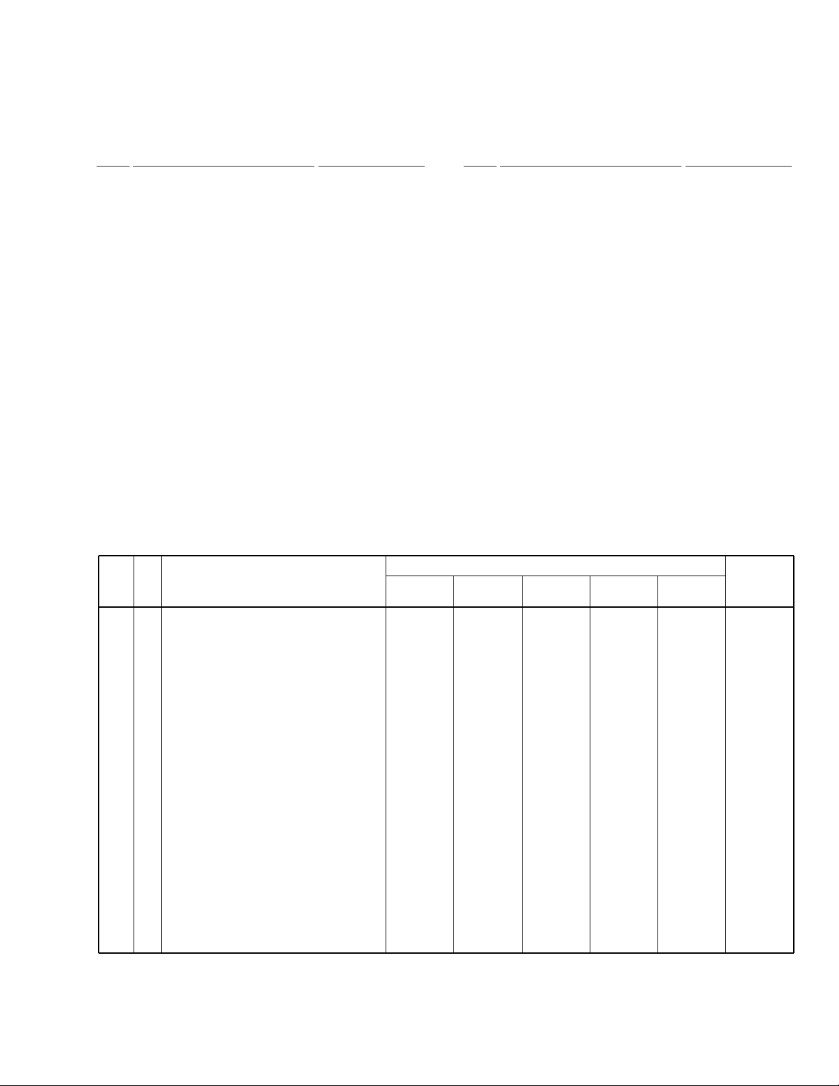
PDV-LC20, PDV-20
3.3 LCD MONITOR SECTION (PDV-LC20 ONLY)
14
17
7
17
2
15
16
6
to B1
20
3
18
17
5
22
12
11
4
17
8
10
9
5
1
7
Note for Assembly
2-1/2
turns
to PDVDM Assy
CN401
Triangle marked
17
13
8
Page 9

(1) LCD MONITOR SECTION PARTS LIST
Mark No. Description Part No.
1 LCD Panel (Service) VXX2737
2 LCD Main (Service) See Contrust table (2)
3 LCD Inverter (Service) VXX2739
4 LCD FFC 6P (Service) VXX2740
5 Connector Assy 2P VKP2257
6 FPC 22P VNP1800
7 Speaker VVY1003
8 LCD Holder VNK4715
9 LCD Locker VNK4717
10 Lock Spring VBH1316
11 Earth Plate VNH1067
12 Mode Button VNK4716
13 Cushion C VEB1323
14 LCD Cover VNK4714
15 Flexible Sheet VEC2084
16 Support Sheet VEC2188
17 Screw VBA1062
18 Free Stopper VXB1002
19 • • • • •
20 Insulation Sheet VEC2168
PDV-LC20, PDV-20
21 • • • • •
22 Volume Dial (Service) VXX2756
(2) CONTRAST TABLE
PDV-LC20/ZU/CA, ZY and ZL are constructed the same except for the following :
Part No.
Mark No. Symbol and Description
2 LCD Main (Service) VXX2738 VXX2748 VXX2748
PDV-LC20
/ZU/CA
PDV-LC20
/ZY
PDV-LC20
/ZL
Remarks
9
Page 10
1
23
PDV-LC20, PDV-20
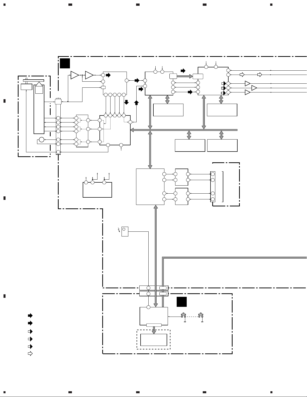
3. BLOCK DIAGRAM AND SCHEMATIC DIAGRAMA
3.1 BLOCKM DIAGRAM
A
78,80-84
DTR1
TXD1
RXD1
CTS1
86,87
27M
MB86373B
91
89
AV Decoder
54
B
TRAVERSE
MECHANISM
ASSY
Spindle
Motor
OEIC
Pickup
Assy
+-
SLED
M
MOTOR
B1-B4
T_RTN
T_DRV
F_DRV
F_RTN
SLDR_F
SLDR_R
CN120
(35P)
11,12
19,20
8
9
6
7
26
27
31
PDVDM ASSY
A
B1-B4
T_RTN
T_DRV
F_DRV
F_RTN
SLDR_F
SLDR_R
SPDO
Q110
RF
IC351
BA5929FP
FTS Driver
11
12
13
14
15
16
27M
6
CY2081SL-638
Clock Generator
16M
27M
107
RFI
3
PDRF
B1-B4
TDO
10
FDO
1
SLDO
20
DSPCLK
(16M)
16M
5
5
LA9701M
6-9
35 42 57 56 46
TE
32 33 30 31 39
48
47
LC78652W
Servo DSP
45
46 14
DACCLK
(33/16M)
33/16M
1
IC101
RF IC
FE
PH
IC201
SPDO
BH
DSPCLK
(16M)
DSPRF
IC901
IR601
REMOTE
SENSOR
54
EFM IN
RFO
3
ROMXA
ROMXA
AIN
170
112
IC602
PD3410A
SH1 ASIC
4
57-60
IC610
PE5108A
DVD Decoder
BY Chip
GM71VS17803CLT-6
63-66
111
IC608
16M DRAM
ADDRESS, DATA BUS
TC74VHCT541AFT
3V→5V Level Shift
DTR
118
TXD
102
RXD
101
CTS
117
TC7WH125FU
5V→3V Level Shift
SD0-SD7
SREQ
56
XSACK
55
CDDATA
IC604
TC55V1001AF8
1M SRAM
IC603
18
2
17
3
2
6
5
3
IC605
36/16M
197
205
64
(V/CB)
(Y)
(C)
IC802
IC606
PD6365A
DTR
5
7
TXD
6
RXD
CTS
4
62
45
39
36
Flash
Memory
Download
IC801
AV-1
HY57V161610DTC-8
16M SDRAM
8M Flash ROM
(7P)
CN601
4
ADAI
ADAO
V_HOUT
Y_HOUT
C_HOUT
ADAI
ADAO
Q851 (2/2)
Q861 (2/2)
Q871 (2/2)
C
PAL, UD/RL, ZOOM,
WIDE, D_MODE,
LOW_PW, LCD_ON
(50P)
CN602
(50P)
CN2001
: RF SIGNAL ROUTE
(TV)
: TV SIGNAL ROUTE
(V/CB)
: V/CB SIGNAL ROUTE
(Y)
: Y SIGNAL ROUTE
D
(C)
: C SIGNAL ROUTE
IR
34
42
85
IC2001
PE5191A
µ-Control IC
23-26,32-48
V2001
VAW1059
LCD
1-7
19-25
B
PDV-20
ONLY
PDVDS ASSY
KEY SW
: AUDIO SIGNAL ROUTE
10
1234
Page 11
ADAI
ADAO
(V/CB)
(Y)
(C)
Video Filter
IC404
PE8001A
DAC IC
2
F801
(V/CB)
(Y)
(C)
16
13
5
Q851 (1/2)
Q871 (1/2)
VOUTL
VOUTR
Q861 (1/2)
IC403
(3/3)
14
IC402 (1/2)
NJU7082BV
2
1
IC852
TK15402M
Video Amp.
VOUT
3
YOUT
12
COUT
7
IC406 (1/2)
NJM2100V
12
2
L
H
13
1
R491
PDV-20 ONLY
IC853
TK15416M
Video Drive
(V/CB)
5 8
(Y)
10
(C)
9
PDV-LC20
ONLY
IC403 :
TC74HC4053AFT
5
4
3
IC403
(2/3)
678
PDV-LC20, PDV-20
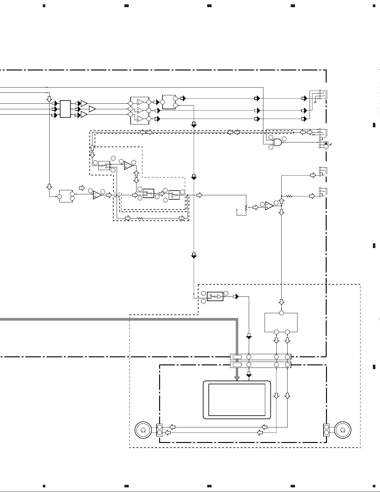
A
JA850
VIDEO
IN/OUT
JA401
AUDIO
IN/OUT
JA402
PHONES 1
JA403
PHONES 2
OPTICAL
B
1
2
2
5
IC403
(1/3)
(V/CB)
IVIDEO
15
(V/CB) (V/CB)
(Y)
(C)
(V)(V)
1
2
IC412
TC7SH08FU
IC407 (1/2)
VREF
NJU7082BV
VR401
10k
1
3
4
R475
(Y)
(C)
RCH
(V)
PDV-LC20
ONLY
L
6
4
H
IC854
MM1507XN
TFT COLOR MINITOR
B3
1
2
SPEAKER L SPEAKER R
(V)
2
PAL, UD/RL, ZOOM,
WIDE, D_MODE,
LOW_PW, LCD_ON
10-16
10-16
15
IC408
LM4863MT
HP & SP Amp.
(V)(V)
Y IN
VIDEO
16 18
SPL-
38
SPL+
438
4
(24P)
CN401
B1
B2
1
2
PDV-LC20
ONLY
C
D
11
5
6
7
8
Page 12
1
23
PDV-LC20, PDV-20
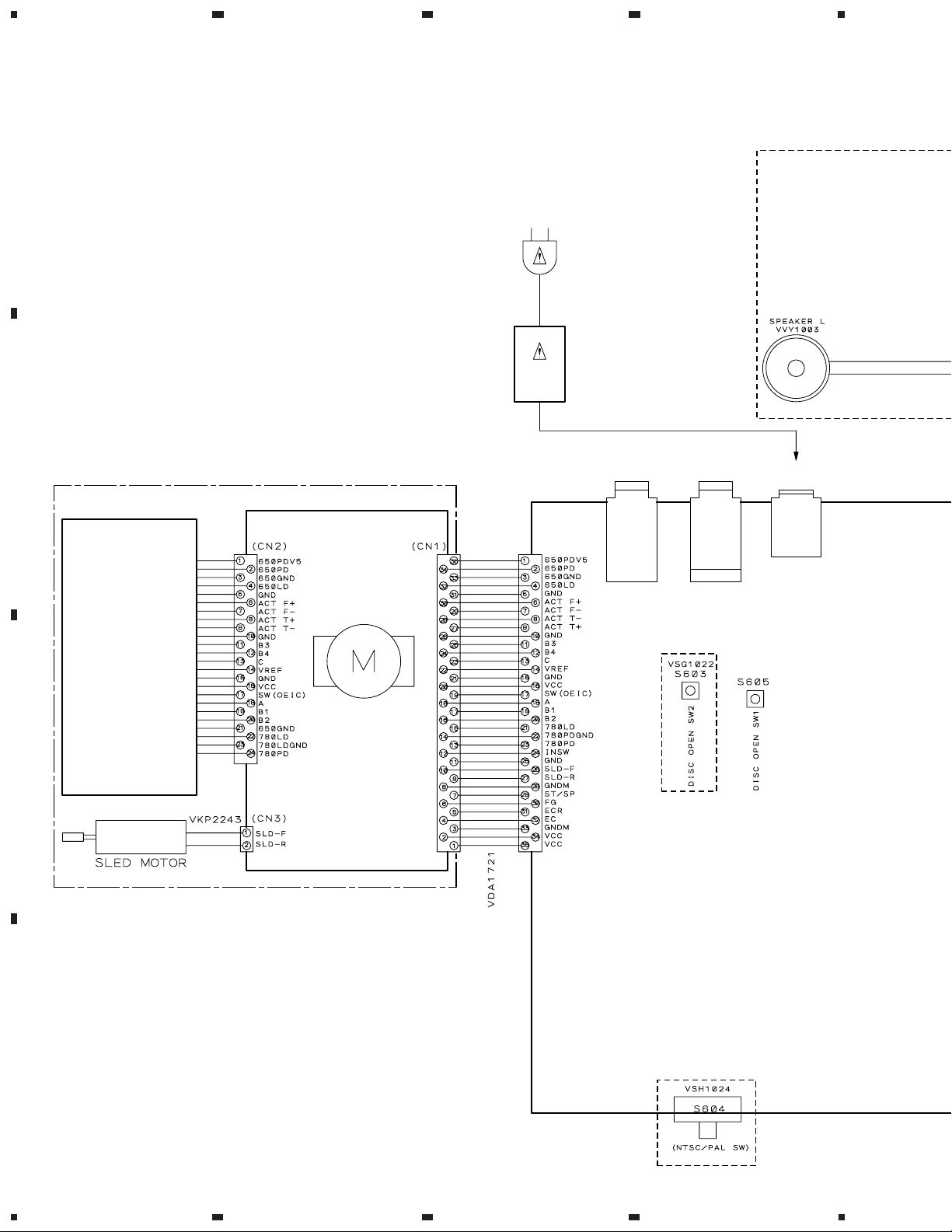
3.2 OVERALL WIRING DIAGRAM
4
A
B
TRAVERSE MECHANISM ASSY (VXX2658)
SPINDLE MOTOR ASSY
ZU/CA : AC120V
ZY, ZL : AC100-240V
AC ADAPTER
ZU/CA, ZY : VWX1228
ZL : VWX1229
CN120
PDV-LC20
ONLY
VIDEO IN/OUT
/S VIDEO OUT
AUDIO IN/OUT
/OPTICAL OUT
JA850 JA401 JA851
DC IN
PICKUP ASSY
ZY, ZL ONLY
C
D
ZY, ZL ONLY
12
1234
Page 13
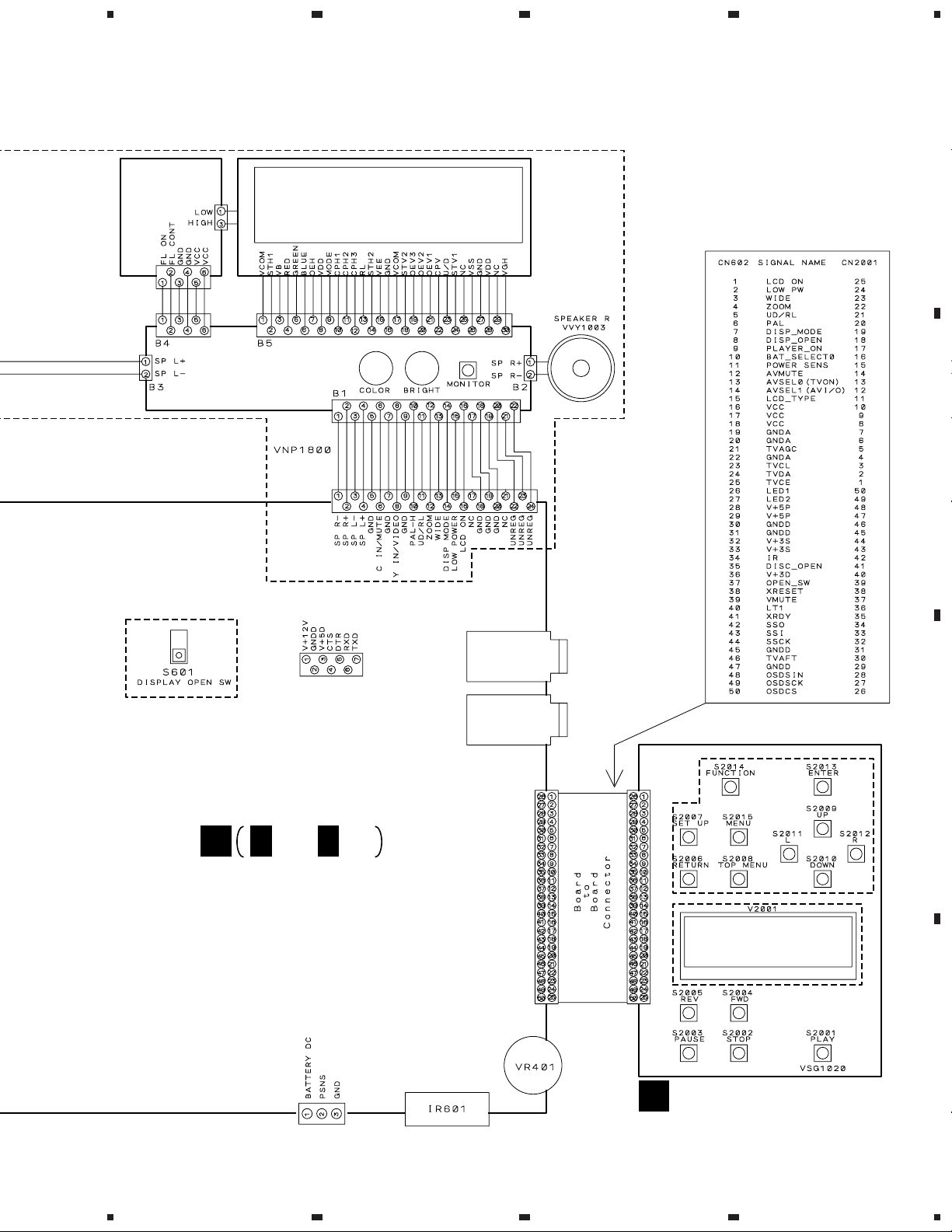
5
678
PDV-LC20, PDV-20
Note : When ordering service parts, be sure to refer to "EXPLODED VIEWS and PARTS LIST" or "PCB PARTS LIST".
LCD INVERTER
(For SERVICE)
(VXX2739)
LCD MAIN (For SERVICE)
(ZU/CA : VXX2738)
(ZY, ZL : VXX2748)
LCD PANEL (For SERVICE)
(VXX2737)
CN401
PDV-LC20
ONLY
A
B
PDV-LC20
ONLY
CN601
DOWNLOAD CONNECTOR
A
A 1/6- A 6/6
PDVDM ASSY
(PDV-LC20/ZU/CA : VWS1456)
(PDV-LC20/ZY, ZL : VWS1457)
(PDV-20/ZY, ZL : VWS1461)
CN11
BATTERY
DC IN
5
REMOTE
RECEIVER UNIT
6
JA402
JA403
CN602
PHONES 1
PHONES 2
CN2001
7
PDV-LC20
ONLY
PDVDS ASSY
B
(PDV-LC20/ZU/CA : VWG2254)
(PDV-LC20/ZY : VWG2255)
(PDV-LC20/ZL : VWG2256)
(PDV-20/ZY : VWG2259)
(PDV-20/ZL : VWG2260)
PDV-20
ONLY
8
C
D
13
Page 14
1
PDV-LC20, PDV-20
3.3 PDVDM ASSY (1/6)
23
4
A
A 1/6
PDVDM ASSY
(PDV-LC20/ZU/CA : VWS1456)
A
3/6
(PDV-LC20/ZY, ZL : VWS1457)
(PDV-20/ZY, ZL : VWS1461)
1
Q106
2SA1576A
(F)
(DVD)
HN1C01FU
Q114
2SC4081
(DVD)
A
3/6
A
2/6
2 4
(CD)
(DVD)
A
2/6
B
(DVD)
A
2/6
(CD)
(F)
(F)
(T)
(T)
C
(S)
TRAVERSE MECHANISM ASSY
D
(S)
A
2/6
Q121
2SC4081
A
2/6
(S)
Q100
2SA1576A
A
2/6
A
2/6
HN1C01FU
(T)
A
2/6
(S)
A
2/6
(S)
(S)
(F)
14
RAB4C220J
RAB4C390J
1/6
A
1234
A
2/6
(S)
(F)
(F)
(T)
(T)
(F)
(T)
Page 15
5
678
PDV-LC20, PDV-20
8
9
A
3/6
10 11
A
2/6
: RF SIGNAL ROUTE
: ROM DATA SIGNAL ROUTE
(F)
: FOCUS SERVO LOOP LINE
(T)
: TRACKING SERVO LOOP LINE
(S)
: SLIDER SERVO LOOP LINE
A
A
2/6
(CD)
Q127
DTC124EUA
A
2/6
HNC01FU
(F) (F)
HNC01FU
A
(CD)
2/6
(T)
A
2/6
A
4/6
B
6
(T)
(T)
(CD)
(S)
(F)
(T)
5
C
7
A
3/6
A
2/6
1/6
A
5
6
7
8
15
D
Page 16
1
PDV-LC20, PDV-20
3.4 PDVDM ASSY (2/6)
23
4
A
A 2/6
PDVDM ASSY
(PDV-LC20/ZU/CA : VWS1456)
(PDV-LC20/ZY, ZL : VWS1457)
(PDV-20/ZY, ZL : VWS1461)
B
PDV-LC20
ONLY
PD6365A
A
5/6
A
6/6
A
5/6
C
REMOTE
RECEIVER
UNIT
ZY, ZL ONLY
A
D
ZU/CA ONLY
1/6
A
5/6
PDV-LC20
ONLY
PDV-20
ONLY
CN2001
B
A
5/6
16
2/6
A
1234
Page 17
5
678
PDV-LC20, PDV-20
A
A
3/6
20MHz
A
5/6
4/6
A
B
A
5/6
A
4/6
A
5/6
A
4/6
A
1/6
A
1/6
A
1/6
C
3/6
A
5/6
A
A
1/6
1/6
A
A
A
1/6
1/6
1/6
A
ZY, ZL
ONLY
RAB4C103J
A
1/6
A
1/6
D
A
3/6
2/6
A
5
6
7
8
17
Page 18
1
PDV-LC20, PDV-20
3.5 PDVDM ASSY (3/6)
23
4
A
B
A 3/6
PDVDM ASSY
(PDV-LC20/ZU/CA : VWS1456)
(PDV-LC20/ZY, ZL : VWS1457)
(PDV-20/ZY, ZL : VWS1461)
A
2/6
C
D
18
3/6
A
1234
Page 19

5
678
PDV-LC20, PDV-20
2/6
A
: RF SIGNAL ROUTE
A
5/6
1/6
: ROM DATA SIGNAL ROUTE
A
A
A
4/6
A
5/6
B
A
1/6
A
1/6
A
1/6
3
(CD)
A
4/6
A
4/6
(CD)
(DVD)(DVD)
C
D
3/6
A
5
6
7
8
19
Page 20

1
PDV-LC20, PDV-20
3.6 PDVDM ASSY (4/6)
A
23
4
A 4/6
PDVDM ASSY
(PDV-LC20/ZU/CA : VWS1456)
(PDV-LC20/ZY, ZL : VWS1457)
(PDV-20/ZY, ZL : VWS1461)
B
A
2/6
C
A
5/6
1714 1512
1613
A
2/6
(Y)
(C)
D
20
4/6
A
1234
(V/CB)
(C)
(Y)
(V/CB)
(C)
(Y)
(V/CB)
A
3/6
Page 21

5
678
PDV-LC20, PDV-20
CLOCK GEN. BLOCK
A
2/6
13.824MHz
: ROM DATA SIGNAL ROUTE
(V/CB)
: V/CB SIGNAL ROUTE
(Y)
: Y SIGNAL ROUTE
(C)
: C SIGNAL ROUTE
: AUDIO SIGNAL ROUTE
A
3/6
A
5/6
A
3/6
A
1/6
A
B
(C)
(Y)
(V/CB)
5
(V/CB)
C
A
5/6
Q852
2SA1576A
Q862
(Y)
(C)
6
2SA1576A
(V/CB)
(Y)
(C)
D
4/6
A
7
8
21
Page 22

1
PDV-LC20, PDV-20
3.6 PDVDM ASSY (5/6)
23
4
A
A
3/6
2/6
A
A
2/6
PDV-LC20
ONLY
2/6
A
PDV-20
IC404
PE8001A
Q403
B
A
4/6
2SD2114K
ONLY
PDV-20
ONLY
Q411
DTC124EUA
Q858
Q419
2SD2114K
A
Q859
A
2/6
DTC124EUA
2/6
DTC124EUA
2/6, 6/6
A
(Y) (Y)
C
(V/CB)
Q856
(V/CB)
(V/CB)
(Y)
(V/CB)
(V/CB)
(V/CB)
PDV-LC20
ONLY
2SD2114K
(Y)
(Y)
(C)
(C)
D
(V/CB)
(C)
(Y)
(V/CB)
A
2/6
(C)
(C)
A
2/6,6/6
(Y)
A
3/6
Q853
2SA1576A
(C)
(V/CB)
VIDEO
IN/OUT
(/S VIDEO OUT)
(/OPTICAL)
PDV-LC20
ONLY
Q854
2SD2114K
AUDIO
IN/OUT
22
A
2/6, 6/6
A
A
5/6
3/6
1234
Page 23

5
678
PDV-LC20, PDV-20
A 5/6
Q381
2SC4081
100/6.3
VCH1216
PDVDM ASSY
(PDV-LC20/ZU/CA : VWS1456)
(PDV-LC20/ZY, ZL : VWS1457)
(PDV-20/ZY, ZL : VWS1461)
PDV-LC20
ONLY
22
: VIDEO SIGNAL ROUTE
(V/CB)
: V/CB SIGNAL ROUTE
(Y)
: Y SIGNAL ROUTE
(C)
: C SIGNAL ROUTE
: AUDIO SIGNAL ROUTE
A
PHONES 2
10
Q412
2SD2114K
Q384
2SC4081
22
2/6
A
Q404
DTC124EUA
22
1/2
10
2/2
22
PHONES 1
PDV-LC20
ONLY
B
LCD MAIN B1
C
2/6, 6/6
A
(V/CB)
5
PDV-LC20
ONLY
Q413
2SD2114K
(V/CB)
PDV-LC20
ONLY
D
5/6
A
6
7
8
23
Page 24

1
PDV-LC20, PDV-20
3.7 PDVDM ASSY (6/6)
A
B
DC IN
9.8V
A 6/6
23
PDVDM ASSY
(PDV-LC20/ZU/CA : VWS1456)
(PDV-LC20/ZY, ZL : VWS1457)
(PDV-20/ZY, ZL : VWS1461)
PDV-LC20
ONLY
PDV-LC20
ONLY
CN11
VKN1766
4
BATTERY
DC IN
A
2/6
C
DC/DC CONVERTER
A
2/6, 5/6
Q17
2SA1898
A
2/6
D
24
6/6
A
1234
Page 25

5
678
PDV-LC20, PDV-20
A
• NOTE FOR FUSE REPLACEMENT
CAUTION -
FOR CONTINUED PROTECTION AGAINST RISK OF FIRE.
REPLACE WITH SAME TYPE AND RATINGS ONLY.
L13
1608
0
: The power supply is shown with the marked box.
B
C
D
6/6
A
5
6
7
8
25
Page 26

1
PDV-LC20, PDV-20
3.8 PDVDS ASSY
PDV-LC20 ONLY
A
B
23
D2023
UDZS6.2B
D2022
UDZS6.2B
4
ZU/CA : 5.6k
ZY : 15k
ZL : 27k
C
ZU/CA : 33k
ZY : 12k
ZL : 68k
D
PDV-20
ONLY
26
B
1234
Page 27

5
678
PDV-LC20, PDV-20
PDVDS ASSY
B
(PDV-LC20/ZU/CA : VWG2254)
(PDV-LC20/ZY : VWG2255)
(PDV-LC20/ZL : VWG2256)
(PDV-20/ZY : VWG2259)
(PDV-20/ZL : VWG2260)
A
B
ZU/CA
S2001 : 3
S2002 : 7
S2003 : 8
S2004 : ¡•¢
S2005 : 4•1
S2006 : RETURN
S2007 : SETUP
S2008 : TOP MENU
S2009 : CURSOL (5)
S2010 : CURSOL (∞)
S2011 : CURSOL (2)
S2012 : CURSOL (3)
S2013 : ENTER
S2014 : FUNCTION
S2015 : MENU
ONLY
ZY, ZL
ONLY
PDV-LC20
ONLY
: The power supply is shown with the marked box.
CN602
A 2/6
C
D
B
5
6
7
8
27
Page 28

PDV-LC20, PDV-20
WAVEFORMS
Note : The encircled numbers denote measuring point in the schematic diagram.
Measurement condition : No. 1 to 4 and 6 to 11 : MJK1, Title 1-chp 1
TP946 (RFI)
1
V: 100mV/div. H: 0.1µS/div.
TP203 (RFO)
2
V: 500mV/div. H: 0.1µS/div.
IC610-pin 170 (A IN)
3
V: 1V/div. H: 0.2µS/div.
No. 5 : CD, ABEX-784 Track 1
No. 12 to 14 : MJK1, Title 1-chp 4
No. 15 to 17 : MJK1, Title 1-chp 5
IC201-pin 1 (EFM)
6
V: 1V/div. H: 0.2µS/div.
DC 2V
IC201-pin 55 (FG)
7
V: 1V/div. H: 5mS/div.
Foot of R261 (FPWM)
8
V: 1V/div. H: 10µS/div.
Foot of R264 (RPWM)
11
V: 1V/div. H: 0.2µS/div.
IC801-pin 45
12
(Composite Video output)
V: 500mV/div. H: 10µS/div.
IC801-pin 39 (Y output)
13
V: 500mV/div. H: 10µS/div.
DC1.4V
GND
IC801-pin 39 (Y output when
16
selecting color difference
outpit)
V: 500mV/div. H: 10µS/div.
IC801-pin 36 (CR output
17
when selecting color
difference outpit)
V: 500mV/div. H: 10µS/div.
GND
TP206 (Tracking Error)
4
V: 1V/div. H: 2mS/div.
IC201-pin 39
5
(EFM before slice)
V: 1V/div. H: 1µS/div.
28
Foot of R262 (VPWM)
9
V: 1V/div. H: 10µS/div.
Foot of R263 (PPWM)
10
V: 1V/div. H: 0.2µS/div.
IC801-pin 36 (C output)
14
V: 500mV/div. H: 10µS/div.
IC801-pin 45 (CB output
15
when selecting color
difference outpit)
V: 500mV/div. H: 10µS/div.
GND
GND
GND
Page 29

PDV-LC20, PDV-20
29
Page 30

1
R
N
Y
23
PDV-LC20, PDV-20
4. PCB CONNECTION DIAGRAM
A
4.1 PDVDM ASSY
PDVDM ASSY
A
B
4
TRAVE
MECHA
ASS
C
CN200
B
D
Q864Q853 IC851 IC853
Q413
Q23-Q26
30
IC501 IC901
IC608
IC603 IC261
IC302
IC610 Q850
IC404
Q112
Q857
IC202
IC201
IC802
IC402
IC852
Q858
IC281IC290
Q121 Q101 Q412
IC403
Q411 Q407
Q402
Q854
IC408
Q410
IC405
A
1234
Page 31

5
678
PDV-LC20, PDV-20
TRAVERSE
MECHANISM
ASSY
NOTE FOR PCB DIAGRAMS :
1. Part numbers in PCB diagrams match those in the schematic
diagrams.
2. A comparison between the main parts of PCB and schematic
diagrams is shown below.
Symbol In PCB
Diagrams
BCE
BCE
D
3. The parts mounted on this PCB include all necessary parts for
several destinations.
For further information for respective destinations, be sure to
check with the schematic diagram.
4. View point of PCB diagrams.
Symbol In Schematic
Diagrams
BCEBCE
BCE
DGG
S
Connector
BCE
DGS
S
Capacitor
Part Name
Transistor
Transistor
with resistor
Field effect
transistor
Resistor array
3-terminal
regulator
A
B
CN2001
B
(VNP1804-B)
DC IN
LCD MAIN
B1
P.C.Board
SIDE A
Chip Part
SIDE A
SIDE B
C
D
64 IC851 IC854IC853
Q23-Q26
Q85912
Q62
Q856
Q860
5
A
6
7
8
31
Page 32

1
6
Q
C
PDV-LC20, PDV-20
A
B
23
PDVDM ASSY
A
4
C
D
Q401
IC890
IC856
IC11
Q12
Q11
Q890 Q891
IC855
Q61IC412
Q612
Q863
Q17
Q405
Q291 Q278
Q102
Q341
Q408
Q110
Q341
IC605
IC407 IC406
Q104
Q100
IC351
Q381 IC380
IC409
Q404
IC101
Q852
Q851 Q8
I
32
Q409 Q403
A
1234
Page 33

5
678
PDV-LC20, PDV-20
A
B
Q104
100
IC406
Q852
Q862
Q851 Q861 Q871
IC801
C
(VNP1804-B)
SIDE B
D
Q606
6
Q608Q609Q611Q107 Q127
IC606
A
7
8
33
IC304IC101
Q106
Q113
Q390
Q114
Q103
IC401
IC602
IC604
5
Page 34

1
PDV-LC20, PDV-20
4.2 PDVDS ASSY
A
B
B
23
PDVDS ASSY
4
C
A
CN602
PDVDS ASSY
B
(VNP1805-B)
SIDE A
D
34
IC2001 IC2081 IC2002
Q2003
Q2004
B
1234
IC2008
IC2003
(VNP1805-B)
Q2001
Q2001 Q2201
IC2202Q2005
IC2201
SIDE B
Page 35

PDV-LC20, PDV-20
Mark No. Description Part No.
Mark No. Description Part No.
5. PCB PARTS LIST
NOTES:•Parts marked by "NSP" are generally unavailable because they are not in our Master Spare Parts List.
The mark found on some component parts indicates the importance of the safety factor of the part.
•
Therefore, when replacing, be sure to use parts of identical designation.
When ordering resistors, first convert resistance values into code form as shown in the following examples.
•
Ex.1 When there are 2 effective digits (any digit apart from 0), such as 560 ohm and 47k ohm (tolerance is shown by J=5%,
and K=10%).
560 Ω→56 × 10
47k Ω→47 × 103→ 473 ........................................................ RD1/4PU 4 7 3 J
0.5 Ω→R50 ..................................................................................... RN2H
1 Ω→1R0 ..................................................................................... RS1P
Ex.2 When there are 3 effective digits (such as in high precision metal film resistors).
5.62k Ω→ 562 × 10
LIST OF WHOLE PCB ASSEMBLIES
Mark Symbol and Description
PDVDM ASSY
PDVDS ASSY
1
→ 561 ........................................................ RD1/4PU 5 6 1 J
R 5 0
1 R 0
1
→ 5621 ...................................................... RN1/4PC 5 6 2 1 F
Part No.
PDV-LC20 PDV-20
/ZU/CA /ZY /ZL /ZY /ZL
VWS1456
VWG2254
VWS1457
VWG2255
VWS1457
VWG2256
VWS1461
VWG2259
K
K
Remarks
VWS1461
VWG2260
PDVDM ASSY
A
VWS1456 and VWS1457 are constructed the same except for the following :
Mark Symbol and Description
R603
R721, R728
R722
R729
S603
S604
PDVDS ASSY
B
VWS1456 VWS1457
RS1/16S0R0J
Not used
Not used
Not used
Not used
Not used
Part No.
Not used
RS1/16S0R0J
RS1/16S153J
RS1/16S103J
VSG1022
VSH1024
VWG2254, VWG2255, VWG2256, VWG2259 and VVWG2260 are constructed the same except for the following :
Mark Symbol and Description
D2023
S2006-S2015
C2023
R2007
R2011
R2012
R2018
R2026, R2033
R2027, R2034
R2028, R2035
VWG2254
UDZS6.2B
VSG1020
CKSRYF104Z16
RS1/16S333J
Not used
RS1/16S473J
RS1/16S562J
RS1/16S273J
RS1/16S563J
RS1/16S154J
VWG2255
UDZS6.2B
VSG1020
CKSRYF104Z16
RS1/16S123J
RS1/16S473J
Not used
RS1/16S153J
RS1/16S273J
RS1/16S563J
RS1/16S154J
Part No.
VWG2256
UDZS6.2B
VSG1020
CKSRYF104Z16
RS1/16S683J
RS1/16S473J
Not used
RS1/16S273J
RS1/16S273J
RS1/16S563J
RS1/16S154J
VWG2259
Not used
Not used
Not used
RS1/16S123J
RS1/16S473J
Not used
RS1/16S153J
Not used
Not used
Not used
VWG2260
Not used
Not used
Not used
RS1/16S683J
RS1/16S473J
Not used
RS1/16S273J
Not used
Not used
Not used
Remarks
Remarks
R2030
R2031
R2032
V2001 FL Tube
NSP
Spacer
RS1/16S822J
RS1/16S103J
RS1/16S153J
Not used
Not used
RS1/16S822J
RS1/16S103J
RS1/16S153J
Not used
Not used
RS1/16S822J
RS1/16S103J
RS1/16S153J
Not used
Not used
Not used
Not used
Not used
VAW1059
VEC2064
Not used
Not used
Not used
VAW1059
VEC2064
35
Page 36

PDV-LC20, PDV-20
Mark No. Description Part No.
Mark No. Description Part No.
PCB PARTS LIST FOR PDV-LC20/ZU/CA UNLESS OTHERWISE NOTED
Mark No. Description Part No.
PDVDM ASSY (VWS1456)
A
SEMICONDUCTORS
IC351 BA5929FP
IC11 BA9737KV
IC901 CY2081SL-638
IC608 GM71VS17803CLT-6
IC802 HY57V161610DTC-8
IC101 LA9701M
IC201 LC78652W
IC408 LM4863MT
IC801 MB86373B
IC854 MM1507XN
IC261,IC281,IC302,IC406 NJM2100V
IC380,IC402,IC407 NJU7082BV
IC602 PD3410A
IC610 PE5108A
IC404 PE8001A
IC604 TC55V1001AF8
IC290,IC403,IC405 TC74HC4053AFT
IC603 TC74VHCT541AFT
IC412 TC7SH08FU
IC304 TC7SHU04FU
IC409 TC7W32FU
IC605 TC7WH125FU
IC852 TK15402M
NSP IC606 FLASH MEMORY IC PD6365A
IC853 TK15416M
Q100,Q106,Q408,Q852,Q853 2SA1576A
Q862 2SA1576A
Q17 2SA1898
Q114,Q121,Q341,Q381 2SC4081
Q403,Q409,Q412,Q413,Q854 2SD2114K
Q856 2SD2114K
Q23 CPH5701
Q127,Q404,Q411,Q858,Q859 DTC124EUA
Q101,Q112,Q113 HN1C01FU
Q104 HN1K03FU
Q24-Q26 MCH6702
Q405,Q410,Q850,Q857 UMD2N
Q107,Q11,Q401,Q402,Q407 UMH1N
Q606,Q611,Q612 UMH1N
Q12 UMH9N
Q102,Q851,Q861,Q871 UMT1N
Q103,Q110,Q608,Q609 UMZ1N
D812 1SS400
D405,D406 DA221
D301 KV1471E
D603 LT1ED67A
D91 RB051L-40
D602 RB501V-40
D93 UDZ12B
D1000,D401-D404,D601 UDZS5.1B
D605-D611 UDZS5.1B
D851,D853,D854 UMZ8.2T
Mark No. Description Part No.
COILS AND FILTERS
F11,F12 CHIP EMI FILTER DTF1098
L403 CHIP COIL (2.2µH) DTL1023
L170,L351,L352 CHIP COIL (4.7µH) DTL1024
L102,L303,L601 LCYA100J2520
L304 LCYA2R7J2520
F401,F402,F404,F405 VTF1096
CHIP SOLID INDUCTOR
F801 VIDEO FILTER VTF1098
L802 CHIP COIL VTL1067
L839 CHIP BEAD VTL1080
L751 CHIP BEAD VTL1084
L11,L15 INDUCTOR VTL1150
L14,L29,L494 INDUCTOR VTL1151
L18,L23,L26 INDUCTOR VTL1154
SWITCHES
S601 VSG1017
S605 VSG1022
CAPACITORS
C25,C27,C31,C36,C38 CCSRCH101J50
C471,C472 CCSRCH221J50
C410,C431 CCSRCH330J50
C616 CCSSCH100D50
C123,C145,C286,C626,C903 CCSSCH101J50
C322 CCSSCH120J50
C135 CCSSCH121J50
C104-C108 CCSSCH150J50
C206,C211 CCSSCH151J50
C307 CCSSCH180J50
C314,C406,C411,C884 CCSSCH220J50
C898,C899 CCSSCH220J50
C151 CCSSCH270J50
C116,C134,C218 CCSSCH470J50
C126,C309 CCSSCH560J50
C281,C282,C308 CCSSCH5R0C50
C124,C132,C283,C284 CCSSCH680J50
C905,C906 CCSSCK2R0C50
C140,C223,C224,C264,C312 CKSQYB105K10
C881,C888,C889 CKSQYB105K10
C437 CKSQYB334K16
C28 CKSQYB474K16
C18,C20,C21,C32,C39 CKSQYF225Z16
C875,C885 CKSQYF475Z10
C24,C29,C30,C35 CKSRYB102K50
C22 CKSRYB103K50
C101,C12,C174,C213,C263 CKSRYB104K16
C311,C43,C438,C439,C46 CKSRYB104K16
C473,C475,C51,C54,C882 CKSRYB104K16
C432,C441 CKSRYB153K50
C23 CKSRYB272K50
C33,C34 CKSRYB273K16
C217,C803,C804,C813,C817 CKSRYF105Z10
C819,C821,C823,C826 CKSRYF105Z10
C829-C831,C833,C902 CKSRYF105Z10
C299 CKSRYF474Z16
C127,C152,C216,C275,C313 CKSSYB102K50
C359,C424,C435 CKSSYB102K50
C133,C136,C203,C220,C225 CKSSYB103K16
C239,C320,C321,C442-C445 CKSSYB103K16
36
Page 37

PDV-LC20, PDV-20
Mark No. Description Part No.
C628,C650,C659 CKSSYB103K16
C1000,C102,C118,C121,C125 CKSSYB104K10
C138,C212,C227,C232,C315 CKSSYB104K10
C317,C353 CKSSYB104K10
C173,C210 CKSSYB222K50
C153,C271-C274 CKSSYB223K16
C209,C325,C352,C360 CKSSYB331K50
C122 CKSSYB391K50
C208,C363,C364 CKSSYB471K50
C237 CKSSYB472K25
C266 CKSSYB473K10
C117,C240 CKSSYB681K50
C137,C261 CKSSYB682K25
C402,C404,C405,C408,C426 CKSSYF103Z50
C428-C430,C448,C456 CKSSYF103Z50
C109,C110,C115,C120,C13 CKSSYF104Z16
C130,C131,C143,C148,C15 CKSSYF104Z16
C150,C16,C172,C175,C202 CKSSYF104Z16
C204,C215,C221,C222,C226 CKSSYF104Z16
C230,C235,C26,C265,C285 CKSSYF104Z16
C287,C319,C331,C342,C351 CKSSYF104Z16
C354,C361,C37,C380,C382 CKSSYF104Z16
C412,C414,C416,C417,C419 CKSSYF104Z16
C425,C433,C454,C461,C601 CKSSYF104Z16
C603-C606,C608-C612 CKSSYF104Z16
C614,C615,C617,C619,C620 CKSSYF104Z16
C622-C625,C627,C629,C630 CKSSYF104Z16
C636,C638,C639,C641-C649 CKSSYF104Z16
C651,C652,C654-C657 CKSSYF104Z16
C660-C665,C670,C808,C838 CKSSYF104Z16
C840,C842,C843,C845,C847 CKSSYF104Z16
C851,C854,C856,C861,C864 CKSSYF104Z16
C871,C874,C892,C896 CKSSYF104Z16
C129,C142,C147,C149,C171 QCH1012
(47µF/6.3V)
C362,C814 (47µF/6.3V) QCH1012
C420,C436 (10µF/10V) VCH1168
C111,C113,C207,C341,C381 VCH1170
(10µF/6.3V)
C640 (10µF/6.3V) VCH1170
Mark No. Description Part No.
R851,R861,R871 RS1/16S1600F
R39 RS1/16S2000F
R43,R47,R51 RS1/16S2001F
R816,R857 RS1/16S2201F
R417,R448 RS1/16S2202F
R837 RS1/16S2401F
R801 RS1/16S2701F
R37,R814 RS1/16S3301F
R41 RS1/16S3302F
R815 RS1/16S3901F
R164,R853,R863,R873 RS1/16S5600F
R50 RS1/16S7501F
R810,R811,R858,R880,R893 RS1/16S75R0F
R428,R460 RS1/16SS1001F
R289 RS1/16SS1503F
R422,R437,R438,R454 RS1/16SS1602F
R464,R465 RS1/16SS1602F
R288 RS1/16SS1801F
R345,R346,R385,R386,R829 RS1/16SS2000F
R287 RS1/16SS6801F
VR401 (10kΩ) VCS1043
Other Resistors RS1/16S J
OTHERS
X601 CHIP CERALOCK (20MHz) DSS1110
IR601 REMOTE RECEIVER UNIT RS-150
VEC-244
P45,P49 CHIP FUSE (500mA) VEK1059
CN401 24P FFC CONNECTOR VKN1464
JA401 VKN1556
OPTICAL STEREO MINI JACK
CN120 35P FFC CONNECTOR VKN1568
CN11 SPRING CONNECTOR VKN1766
JA850 MINI JACK VKN1768
CN601 7P FFC CONNECTOR VKN1770
CN602 50P CONNECTOR VKN1773
JA402,JA403 STEREO MINI JACK VKN1777
JA851 DC IN JACK VKN1780
X901 CRYSTAL (20MHz) VSS1147
C40-C42,C44,C45 (22µF/16V) VCH1171
C47-C50,C52,C53 (22µF/16V) VCH1171
C17,C19,C355 (22µF/20V) VCH1172
C139,C409,C415,C423,C434 VCH1173
C850,C901 (22µF/6.3V) VCH1173
C446,C447,C878 (33µF/10V) VCH1175
C860 (470µF/4V) VCH1176
C413,C422,C876 (100µF/6.3V) VCH1216
RESISTORS
R608 RAB4C103J
R121 RAB4C220J
R123 RAB4C390J
R818 RS1/16S1001F
R817 RS1/16S1002F
R859 RS1/16S1202F
R804,R892 RS1/16S1301F
R46 RS1/16S1302F
R40,R58,R802 RS1/16S1501F
R44,R48,R52 RS1/16S1502F
(22µF/6.3V)
PDVDM ASSY (VWS1461)
A
SEMICONDUCTORS
IC351 BA5929FP
IC11 BA9737KV
IC901 CY2081SL-638
IC608 GM71VS17803CLT-6
IC802 HY57V161610DTC-8
IC101 LA9701M
IC201 LC78652W
IC801 MB86373B
IC261,IC281,IC302 NJM2100V
IC380,IC402,IC407 NJU7082BV
IC602 PD3410A
IC610 PE5108A
IC404 PE8001A
IC604 TC55V1001AF8
IC290 TC74HC4053AFT
IC603 TC74VHCT541AFT
IC412 TC7SH08FU
IC304 TC7SHU04FU
IC605 TC7WH125FU
IC852 TK15402M
37
Page 38

PDV-LC20, PDV-20
Mark No. Description Part No.
IC853 TK15416M
NSP IC606 FLASH MEMORY IC PD6365A
Q100,Q106,Q408,Q852,Q862 2SA1576A
Q17 2SA1898
Q114,Q121,Q341,Q381 2SC4081
Q403,Q409,Q412,Q413 2SD2114K
Q23 CPH5701
Q127,Q859 DTC124EUA
Q101,Q112,Q113 HN1C01FU
Q104 HN1K03FU
Q24-Q26 MCH6702
Q850,Q857 UMD2N
Q107,Q11,Q401,Q402,Q407 UMH1N
Q606,Q611,Q612 UMH1N
Q12 UMH9N
Q102,Q851,Q861,Q871 UMT1N
Q103,Q110,Q608,Q609 UMZ1N
D405,D406 DA221
D301 KV1471E
D603 LT1ED67A
D91 RB051L-40
D602 RB501V-40
D93 UDZ12B
D1000,D401-D404,D601 UDZS5.1B
D605-D610 UDZS5.1B
D851,D853,D854 UMZ8.2T
COILS AND FILTERS
F12 CHIP EMI FILTER DTF1098
L403 CHIP COIL (2.2µH) DTL1023
L170,L351,L352 CHIP COIL (4.7µH) DTL1024
L102,L303,L601 LCYA100J2520
L304 LCYA2R7J2520
F401,F402,F404,F405 VTF1096
CHIP SOLID INDUCTOR
F801 VIDEO FILTER VTF1098
L802 CHIP COIL VTL1067
L839 CHIP BEAD VTL1080
L751 CHIP BEAD VTL1084
L11,L15 INDUCTOR VTL1150
L14 INDUCTOR VTL1151
L18,L23,L26 INDUCTOR VTL1154
SWITCHES
S603,S605 VSG1022
S604 VSH1024
CAPACITORS
C25,C27,C31,C36,C38 CCSRCH101J50
C471,C472 CCSRCH221J50
C410,C431 CCSRCH330J50
C616 CCSSCH100D50
C123,C145,C286,C626,C903 CCSSCH101J50
C322 CCSSCH120J50
C135 CCSSCH121J50
C104-C108 CCSSCH150J50
C206,C211 CCSSCH151J50
C307 CCSSCH180J50
C314,C406,C411,C884 CCSSCH220J50
C898,C899 CCSSCH220J50
C151 CCSSCH270J50
C116,C134,C218 CCSSCH470J50
C126,C309 CCSSCH560J50
Mark No. Description Part No.
C281,C282,C308 CCSSCH5R0C50
C124,C132,C283,C284 CCSSCH680J50
C905,C906 CCSSCK2R0C50
C140,C223,C224,C264,C312 CKSQYB105K10
C881 CKSQYB105K10
C28 CKSQYB474K16
C18,C20,C21,C32,C39 CKSQYF225Z16
C875,C885 CKSQYF475Z10
C24,C29,C30,C35 CKSRYB102K50
C22 CKSRYB103K50
C101,C12,C174,C213,C263 CKSRYB104K16
C311,C43,C46,C51,C54 CKSRYB104K16
C23 CKSRYB272K50
C33,C34 CKSRYB273K16
C217,C803,C804,C813,C817 CKSRYF105Z10
C819,C821,C823,C826 CKSRYF105Z10
C829-C831,C833,C902 CKSRYF105Z10
C299 CKSRYF474Z16
C127,C152,C216,C275,C313 CKSSYB102K50
C359,C424,C435 CKSSYB102K50
C133,C136,C203,C220,C225 CKSSYB103K16
C239,C320,C321,C442-C445 CKSSYB103K16
C628,C650,C659 CKSSYB103K16
C1000,C102,C118,C121,C125 CKSSYB104K10
C138,C212,C227,C232,C315 CKSSYB104K10
C317,C353 CKSSYB104K10
C173,C210 CKSSYB222K50
C153,C271-C274 CKSSYB223K16
C209,C325,C352,C360 CKSSYB331K50
C122 CKSSYB391K50
C208,C363,C364 CKSSYB471K50
C237 CKSSYB472K25
C266 CKSSYB473K10
C117,C240 CKSSYB681K50
C137,C261 CKSSYB682K25
C402,C404,C405,C408,C426 CKSSYF103Z50
C428-C430 CKSSYF103Z50
C109,C110,C115,C120 CKSSYF104Z16
C130,C131,C143,C148,C150 CKSSYF104Z16
C16,C172,C175,C202,C204 CKSSYF104Z16
C215,C221,C222,C226,C230 CKSSYF104Z16
C235,C26,C265,C285,C287 CKSSYF104Z16
C319,C331,C342,C351,C354 CKSSYF104Z16
C361,C37,C380,C382,C412 CKSSYF104Z16
C414,C416,C433,C461,C601 CKSSYF104Z16
C603-C606,C608-C612 CKSSYF104Z16
C614,C615,C617,C619,C620 CKSSYF104Z16
C622-C625,C627,C629,C630 CKSSYF104Z16
C636,C638,C639,C641-C649 CKSSYF104Z16
C651,C652,C654-C657 CKSSYF104Z16
C660-C665,C670,C808,C838 CKSSYF104Z16
C840,C842,C843,C845,C847 CKSSYF104Z16
C851,C854,C856,C861,C864 CKSSYF104Z16
C871,C874,C896 CKSSYF104Z16
C129,C142,C147,C149,C171 QCH1012
(47µF/6.3V)
C362,C814 (47µF/6.3V) QCH1012
C420,C436 (10µF/10V) VCH1168
C111,C113,C207,C341,C381 VCH1170
(10µF/6.3V)
C640 (10µF/6.3V) VCH1170
38
Page 39

PDV-LC20, PDV-20
Mark No. Description Part No.
C40-C42,C44,C45 (22µF/16V) VCH1171
C47-C50,C52,C53 (22µF/16V) VCH1171
C17,C19,C355 (22µF/20V) VCH1172
C139,C409,C415,C423,C434 VCH1173
(22µF/6.3V)
C850,C901 (22µF/6.3V) VCH1173
C446,C447,C878 (33µF/10V) VCH1175
C860 (470µF/4V) VCH1176
C413,C876 (100µF/6.3V) VCH1216
RESISTORS
R608 RAB4C103J
R121 RAB4C220J
R123 RAB4C390J
R818 RS1/16S1001F
R817 RS1/16S1002F
R859 RS1/16S1202F
R804,R892 RS1/16S1301F
R46 RS1/16S1302F
R40,R58,R802 RS1/16S1501F
R44,R48,R52 RS1/16S1502F
R851,R861,R871 RS1/16S1600F
R39 RS1/16S2000F
R43,R47,R51 RS1/16S2001F
R816,R857 RS1/16S2201F
R417,R448 RS1/16S2202F
R837 RS1/16S2401F
R801 RS1/16S2701F
R37,R814 RS1/16S3301F
R41 RS1/16S3302F
R815 RS1/16S3901F
R164,R853,R863,R873 RS1/16S5600F
R50 RS1/16S7501F
R810,R858,R880,R893 RS1/16S75R0F
R428,R460 RS1/16SS1001F
R289 RS1/16SS1503F
Mark No. Description Part No.
PDVDS ASSY
B
SEMICONDUCTORS
IC2001 PE5191A
IC2002 PST9330U
IC2003 TK71533SCL
IC2008 TK71550SCL
Q2004 2SA1576A
Q2001 2SB970
Q2002,Q2003,Q2005 UMH1N
D2022,D2023 UDZS6.2B
SWITCHES
S2001-S2015 VSG1020
CAPACITORS
C2002 CKSRYB102K50
C2004 CKSRYB103K50
C2001,C2003,C2006-C2010 CKSRYF104Z16
C2022,C2023 CKSRYF104Z16
C2005,C2011 (10µF/6.3V) VCH1170
RESISTORS
R2045,R2080 RAB4C473J
R2003 RS1/16S1601F
R2004 RS1/16S5600F
Other Resistors RS1/16S J
OTHERS
CN2001 50P CONNECTOR VKN1772
X2001 VSS1102
CHIP CERAMIC RESONATOR (5MHz)
R422,R454 RS1/16SS1602F
R288 RS1/16SS1801F
R345,R346,R385,R386,R829 RS1/16SS2000F
R287 RS1/16SS6801F
VR401 (10kΩ) VCS1043
Other Resistors RS1/16S J
OTHERS
X601 CHIP CERALOCK (20MHz) DSS1110
IR601 REMOTE RECEIVER UNIT RS-150
P45,P49 CHIP FUSE (500mA) VEK1059
JA401 VKN1556
OPTICAL STEREO MINI JACK
CN120 35P FFC CONNECTOR VKN1568
CN11 SPRING CONNECTOR VKN1766
JA850 MINI JACK VKN1768
CN601 7P FFC CONNECTOR VKN1770
CN602 50P CONNECTOR VKN1773
JA402,JA403 STEREO MINI JACK VKN1777
JA851 DC IN JACK VKN1780
X901 CRYSTAL (20MHz) VSS1147
6. ADJUSTMENT
There is no information to be shown in this chapter.
39
Page 40

PDV-LC20, PDV-20
7. GENERAL INFORMATION
7.1 DIAGNOSIS
7.1.1 DISASSEMBLY
Traverse Mechanism Assy
PDV-LC20 Only
Open the LCD
2
Monitor section
Body
3
×9
1
PDV-LC20 Only
LCD Monitor
5
Section
Turn the LD Short SW to short position
8
Pickup Flexible
Cable
Mechanism Side
Traverse Board
Note :
In assembling, style the fold part of
flexible cable to the upper side of the
PDVDM Assy.
Be careful so that the fold part does not
get on the Traverse Board in the case.
Traverse Mechanism
Assy
11
LD Short SW
Open
Short
CN2
9
10
CN602
PDVDM
Assy
PDVDM
Assy
×2
4
∗1
IR Filter
LED Lens
Rear Cover
6
CN401CN401
∗1
Stopper
Spring
Open
Knob
∗1
∗1
Note ∗1 : Remove ∗1 marked parts before hand because it
may be lost.
(There is not influence in the Disassembly)
40
CN602CN602
PDVDS
Assy
7
Page 41

PDV-LC20, PDV-20
Diagnosis the Traverse Mechanism Assy
Traverse Mechanism
Assy
Fix the Flexible cable with Tape
so that it does not touch the disc.
Flexible Cable
(for Service)
(VXX2658)
LCD Monitor Section (PDV-LC 20 Only)
3
LCD Monitor Section
(PDV-LC20 Only)
Hold the Door Switch with Tape,
and keep on with the ON state.
ZU/CA Type : 1 switch
ZY, ZL Types : 2 switches
PDVDM Assy
PDVDS Assy
LCD Cover and LCD Holder hold it with the hook, and be easy to put scratch
when they remove it.
Therefore remove it by nails of a finger not to put scratch when removing it.
Insulation
Sheet
LCD Inverter
Do not touch it during
electricity for
high voltage unit
Speaker
5
-1
6
4
LCD Panel
LCD Holder
×4
2
Cushion C
1
-2
6
∗2
Lock Spring
×4
LCD Cover
5
×2
5
6
LCD Main
4
4
Earth Plate
Speaker
7
LCD Locker
∗1
∗1
Note ∗1 : Remove ∗1 marked parts before hand because it
may be lost.
(There is not influence in the Disassembly)
Note ∗2 : Be careful not to touch the screen surface of LCD by hand.
41
Page 42

PDV-LC20, PDV-20
Diagnosis the LCD Monitor Section
LCD Panel
LCD FFC 6P (for Service)
(VXX2740)
Do not touch it during
electricity for
high voltage unit
LCD Main
LCD Inverter
Confirmation / Adjustment of a LCD Monitor part
After replacement of LCD Panel, if playbacks with the Test Disc and the General Disc and there is not a problem,
adjustment is unnecessary.
When feel that the picture is inferior, refer to the service manual "PDV-LC20 Confirmation / Adjustment of a LCD
Monitor part (RRV2401)" and perform the confirmation and adjustment.
42
Page 43

7.1.2 TROUBLE SHOOTING
• No Power ON
• TFT is not turned ON
• LCD indication is unusual
PDV-LC20, PDV-20
START
Is TFT turn ON ?
Yes
Is the indication
of LCD normal ?
Yes
Does the spindle
motor turn ?
Yes
POWER ON
No
No
No
• Check DC voltage of DC9V (PDVDM Assy TP14), input check
• PDVDM Assy : Open D91 and check F11
• Check each voltage (PDVDM Assy)
V+5A (TP16), V5DR (TP17), V+5S (TP18), V+5V (TP19),
V+5D (TP20), V+3D (TP21), V2R5 (TP22)
If above voltage are not supplied, check the transistors.
TP16, TP17 = Q23, TP18, TP19, TP20 = Q24, TP21 = Q25, TP22 = Q26
• Check the connection between CN602 of PDVDM Assy and CN2001
of PDVDS Assy
• Check each voltage
PDVDM Assy V+3D (TP636)
PDVDS Assy IC2001-pin 66, CN2001-pin 43, pin 44 (V+3S)
• Check the connection between CN1 of Traverse Mechanism Assy and
CN120 of PDVDM Assy
• Check the voltage of PDVDM Assy V+5S
• Check the voltage of VCC of PDVDM Assy TP125, TP139, TP140
Do the video and
sound come on ?
Yes
OK
No
Check the connection between CN401 of PDVDM Assy and B1 of LCD Main.
43
Page 44

PDV-LC20, PDV-20
7.2 IC
• The information shown in the list is basic information and may not correspond exactly to that shown in the schematic diagrams.
List of IC
•
LC78652W, PD3410A, MB86373B
LC78652W (PDVDM ASSY : IC201)
• Servo DSP IC
Block Diagram
•
TILTE
RF_PH
RF_BH
JITT
HFLIO
TES
PP2/EVENT
SLCIST1,2
EFMIN
SLCO1,2
EFMOUT
PCKIST1,2
DVDFR
CDFR
PD01-3
DVDSYNC
PCK
LEFM
LEFM2
VPDO
VCOC
XIN
XOUT
XTALOUT
ADRAO
CSB
WRB
RDB
P0-7
BUSYB
LASER
FBUSYB
PP0-3
FE
TE
FG
JV
33
32
29
30
31
28
51
26
56
55
34,35
39
36,37
1
87,88
90
91
83-85
92
96
93
100
97
81
80
14
15
8
94
58
60
59
63-70
73
52
7
53,54
,56
MPX
8bit
A/D
CMP
Track Counter
Event Counter
FG Counter
SLC
PLL
Frame Synchronous
Detection, Protection,
Clock
Generator
Command
Interface
Deemphasis Filter
General Purpose Register
Servo
Processor
(16×16+32→32)
CLV
DVD Lock
Detection
Insertion EFM
Demodulation
Error Detect
Correction
C1-Twofold,
C2-Fourfold
Supplement/Mute
D Attenuate
8bit
D/A
Sub Code
Decode
CRC
For De-Interleave
16k SRAM
Serial Out
DOUT
47
48
45
46
44
43
42
24
22
95
23
21
77
74
75
76
17
12
10
18
11
9
20
5
4
3
2
19
25,27
38,50
57
FDO
TDO
SLDO
SPDO
TBAL
TILTDO
AUXO
DRF
FAST
DVDSYEQ
V_PB
FSEQ
WRQ
SQOUT
CQCKB
RWC
EMPH
PW
SBCK
SBSY
SFSY
FSX
EFLG
LRSY
ROMCK
ROMXA
C2F
DOUT
TEST1-4
RESB
44
Page 45

Pin Function
•
.oNemaNniPO/InoitcnuF
1TUOMFEO MFEeulavdetats-yranibsawtahtetatsehttuptuO
2F2COtuptuogalf2C
3AXMORO tuptuoatadMOR-DC
4KCMORO tuptuoatadMOR-DCroftuptuokcolctfihS
5YSRLO tuptuoatadMOR-DCroftuptuokcolcR/L
63PPO/I tuptuoDO-hcNtupnilangis.cnysDVD/tuptuo/tupnitropesoprup-lareneG
7BYSUBFO tuptuoDO-hcNnoitarepossecorpPSDfotuptuolangisysuB
8TUOLATXO tuptuokcolcmetsyslanretxE
9XSFO tuptuolangis.cnysemarf1DC
01KCBSI tupnikcolctuognidaeredocbuS
11YSFSO edocbusfotuptuolangis.cnysemarF
21WPO tuptuoWdnaV,U,T,S,R,Q,PedocbuS
31SSV
41NIXI )zHM4439.61(rotanoserlatsyrcatcennoC
51TUOXO rotanoserlatsyrcatcennoC
611DDVD
71HPMEO sisahpmeedehtfoniprotinoM
81YSBSO kcolbedocbusehtfotuptuolangis.cnyS
91TUODO tuptuoatadJAIEoiduA
02GLFEO 2Cdna1CnoitcerrocrorreehtforotinometatsnoitcerrocrorrE
12QESFO langis.cnysemarfDVD/DCehtforotinomnoitceteD
22TSAFO tuptuoDO-hcNrotinomdeepskcabyalP
32BP_VO lortnocVLC/ovreshguorehtfotuptuorotinoM
42FRDO rotinomsucofnI
523TSETI3tupnitseT
62SETI tupnilangisrorregnikcarT
722TSETI2tupnitseT
82TTIJI LLPMFEfotupnilangisgnitcetedytitnauqrettiJ
92ETLITI tupnilangisrorretliT
03HP_FRI tupnilangisdlohkaepFR
13HB_FRI tupnilangisdlohmottobFR
23
ET
33EFI tupnilangisrorresucoF
431TSICLS
532TSICLS
631OCLSO CLSrof1tuptuolortnoC
732OCLSO CLSrof2tuptuolortnoC
831TSETI1tupnitseT
93NIMFEI tupni+MFE/MFE
04DDVA
14SSVA
24OXUAO tuptuoyrailixuaAD
34ODTLITO tuptuolangislortnoctliT
44LABTO tuptuolangislortnocecnalabgnikcarT
54ODLSO tuptuolangislortnocdelS
64ODPSO tuptuolangislortnoceldnipS
74ODFO tuptuolangislortnocsucoF
84ODTO tuptuolangislortnocgnikcarT
94FERV
054TSETI4tupnitseT
−
−
ItupnilangisrorregnikcarT
−
−
−
−
−
nipDNG
tiucricnoitallicsoehtfoylppusrewopV3.3
ovresrofA/DdnaD/AfoylppusrewopV5
ovresrofA/DdnaD/AfoDNG
ovresrofA/DfolevelecnerefeR
PDV-LC20, PDV-20
CLSrofpmupegrahctnerructnatsnocehtfo1nipgnittestnerruC
CLSrofpmupegrahctnerructnatsnocehtfo2nipgnittestnerruC
45
Page 46

PDV-LC20, PDV-20
.oNemaNniPO/InoitcnuFniP
15OILFHO/Ituptuo/tupnilangisnoitcetedrorriM
25RESALO lortnocFFO/NOresalrofniptuptuO
35BDC_DVD/0PPO/ItuptuolangisnoitanimircsidcsiD/tuptuo/tupnitropesoprup-lareneG
45BRRECRC/1PPO/I tuptuolangistluserCRCedocbuS/tuptuo/tupnitropesoprup-lareneG
55GFI tupniretnuocGF
65TNEVE/2PPO/ItupniretnuoctnevE/tuptuo/tupnitropesoprup-lareneG
75BSERItupniteseR
85BSCI tupnitcelespihC
95BDRI tupnilangisgnidaeretatslanretnI
06BRWI tupnilangisgnitirwatad/dnammoC
162DDVD
26SSV
360P
461P
562P
663P
764P
865P
966P
077P
17SSV
271DDVD
37BYSUBO ssecorpdnammocfotuptuolangisysuB
47TUOQSO QedocbusfotuptuolaireS
57BKCQCI tuptuoatadQedocbusroftupnikcolctfihS
67CWRI QedocbusfotupninoissimrepetadpU
77QRWO QedocbusforotinomydaertuodaeR
87SSVA
97RFPRV
08COCVI
18ODPVO
28
DDVA
381ODPO/IkcabyalpMFErof1nipnoitcennocretlifLLP
482ODPO/IkcabyalpMFErof2nipnoitcennocretlifLLP
583ODPO/IkcabyalpMFErof3nipnoitcennocretlifLLP
68SSVA
781TSIKCP
882TSIKCP
98DDVA
09RFDVD
19RFDC
29VJO kcabyalpMFErofkcolcLLPfotuptuorettiJ
39KCPO kcabyalpMFEroftuptuokcolctiB
49OARDAItupnisserddA
59QEYSDVDI tupnieslupezinorhcnysDVD
69CNYSDVDI tupnilangissuonorhcnysDVD
792MFELO 2KCPhtiwMFEeulavdetats-yranibsawhcihwlangisatuodnatuctahtetatsehttuptuO
891DDVD
99SSV
001MFELO 1KCPhtiwMFEeulavdetats-yranibsawhcihwlangisatuodnatuctahtetatsehttuptuO
−
−
O/Ituptuo/tupniatad/dnammoC
−
−
−
−
−
−
−
−
−
−
−
−
−
DNG
DNG
DNG
ylppusrewopV5
lanretnirofylppusrewopV3.3
kcolcmetsyslanretnirofDNGLLP
kcolcmetsysrofretlifLLPatcennoC
kcolcmetsysrofylppusrewopV5LLP
kcabyalpMFErofDNGLLP
kcabyalpMFErofylppusrewopV5LLP
O/IrofylppusrewopV3.3
kcolcmetsysrofLLPfognittesegnarnoitallicsoOCV
kcabyalpMFErofpmupegrahctnerructnatsnocLLPfo1gnittestnerruC
kcabyalpMFErofpmupegrahctnerructnatsnocLLPfo2gnittestnerruC
1kcabyalpMFErofLLPfognittesegnarnoitallicsoOCV
2kcabyalpMFErofLLPfognittesegnarnoitallicsoOCV
46
Page 47

PD3410A (PDVDM ASSY : IC602)
• System Control IC
Pin Function
•
.oNkraMemaNniPO/InoitcnuF
1LSACX/3SCX3SCXO tuptuolangistcelespihc)PIHCYM(A5994DP
2DNGDNG − DNG
3KCKCUPCHO
4CCVD3+V − D3+V
5KLCIP − O/I.C.N
6ATADIP − O/I.C.N
7DNGDNG − DNG
80HTROP0PSSCXOdesutoN
91HTROPHVM33OdesutoN
012HTROPHVM63OdesutoN
113HTROP2LES_VOdesutoN
21CCVD3+V − D3+V
314HTROPNOATCSOdesutoN
415HTROPHVM72OdesutoN
516HTROPDPSSCXOdesutoN
617HTROP
71DNGDNG − DNG
81LATXELATXEI
91LATXLATXO
02CCVD3+V − D3+V
120GTROP0FDSCXO tuptuolangistcelespihcCAD
221GTROP
322GTROP
423GTROPLESBIHOdesutoN
524GTROP
62DNGDNG −
725GTROP
826GTROP
927GTROP
030FTROP84X44O tuptuolangisgnihctiwsSF84/44CAD
131FTROPTPCXI noitcetedtupnikcajtuolatigidlacitpO
232FTROP
33CCVD3+V − D3+V
433FTROP
534FTROP
635FTROP
/TSRDUAX
/FFOPV
OHCE
/1FDSCX
/2FDSCX
/1TSRFD
NO_CIMX
/NOEFL
0TSRFD
/DMHC6
FFOAMX
/DMSTD
/TSRMX
PSADX
MTUMX
/NOD3
44X84
1CNYS
CSID
OdesutoN
rotanosercimarecatcennoC
OdesutoN
PSADSCX
OdesutoN
OdesutoN
DNG
OdesutoN
O)tiucrichctiwS(WS
/ETUMAX
OoiduaehtfotuptuolangisetumegatstsaL
/ETUMMX
OdesutoN
/0PSDASCX
OdesutoN
/1PSDASCX
/TR_SVAX
OdesutoN
/2PSDASCX
OdesutoN
DDO/SOPD
PDV-LC20, PDV-20
47
Page 48

PDV-LC20, PDV-20
.oNkraMemaNniPO/InoitcnuF
736FTROP
837FTROP
93DNGDNG
04SSVADNG
14CCVAD3+V
24P_ATUOVRDOLOdesutoN
34FERVD3+V
44P_BTUOIETO tuptuolangistesffognikcarT
54SSVADNG
64SSVADNG
740ETROPLES_VOdesutoN
841ETROPMGDCIdesutoN
942ETROP???MEOI
053ETROP1TSFOFO/I1tuptuotnemtsujdatesffosucoF
154ETROP2TSFOFO/I2tuptuotnemtsujdatesffosucoF
255ETROPHNIFDXO/ItuptuolangistnuhstcefeD
356ETROPDCX/DVDO tuptuolangisgnihctiwsDC/DVD
457ETROPNO_1DLO tuptuolangisNOedoidresalmn056
550DTROPNO_2DLO tuptuolangisNOedoidresalmn087
65CCVD3+V
751DTROPET/DPDO tuptuolangisgnihctiwssmaeb3/maeb1
852DTROPFFOGAO CIFRfotuptuolangisgnihctiwsFFO/NOCGA
953DTROPX2DCXO kcabyalpdeepselbuodehtgnihctiwsroftuptuolangiS
064DTROPGCIEOO tuptuolangisgnihctiwsniagCIEO
16DNGDNG
265DTROPNOMXO rotomeldnipsehtfotuptuognihctiwsFFO/NOtuptuolortnoC
366DTROPACBXOdesutoN
467DTROP
560JTROPTUMVRDXO tuptuoetumrevirD
661JTROPDLX/RDOdesutoN
762JTROPTSRPSDXOdesutoN
863JTROP
96CCVD3+V
074JTROPTNE_MTI tupniedomtseT
175JTROPEPXEXOdesutoN
276JTROPWS_LESVIdesutoN
377JTROPYSQDIdesutoN
472ACOIT/0BPYSUBCXI tupniysubdnammoC
572BCOIT/1BPYSUBAXI tupniysubecneuqes-otuA
673ACOIT/2BP
77CCVD3+V
873BCOIT/3BP1TLO rellortnocLFehtottuptuolangisesnopsernoitacinummoC
974ACOIT/4BPYSBSI tupni.cnyskcolbedocbuS
08TSETMX
18DMUPCX
28SERXTESERXItupniteseR
−
−
/TSREQVX
RNAX
/EVSCX
EQVSCX
TSR???X
OM_CM
/2TNIX
2QRIVAX
OdesutoN
OdesutoN
DNG
−
DNG
−
D3+V
−
D3+V
−
DNG
−
DNG
−
D3+V
−
DNG
−
/WS_NEPO
IrotcennocmsinahceM
/KCAJNM
IdesutoN
D3+V
−
I)1-VA(2tupnitpurretnI
D3+V
−
ID3+V
ID3+V
48
Page 49

.oNkraMemaNniPO/InoitcnuF
38DNGDNG
480NASOPDOLI tupninoitisopgnidaoL
581NASOPDLSI tupninoitisopredilS
682NAWSROODIdesutoN
783NAWS_PANI tupniWSLAP/OTUA/CSTN
884NAI
985NAI
096NAI
197NAWS_PI525IdesutoN
29fervAD3+V
39CCVAD3+V
49SSVADNG
594BCOIT/5BP
69CKLCT/4AXCOIT/6BPF2CItupnirorre2C
79DKLCT/4BXCOIT/7BPYDRXI rellortnocLFehtmorftupnitseuqeroitacinummoC
890DxR/8BPISSI )rellortnocLF(tupniatadlaireS
990DxT/9BPOSSO )CAD,rellortnocLF(tuptuoatadlaireS
001CCVD3+V
1011DxR/01BPDXRI C232-SRehtfotupniataD
2011DxT/11BPDXTO C232-SRehtfotuptuoataD
3010KCS/4QRIX/21BPKCSSO/I)CAD,rellortnocLF(tuptuokcolclaireS
4011KCS/5QRIX/31BP01LQRIXI )PIHCYM(1tupnitpurretnI
501DNGDNG
6016QRIX/41BP11LQRIXI )PIHCYM(2tupnitpurretnI
7017QRIX/51BP
8010ACOIT/4SCX/0AP4SCXO tuptuolangistcelespihcPSDovreS
901SARX/5SCX/1AP.C.NO noitcennocnoN
0110BCOIT/6SCX/2AP6SCXO tuptuolangistcelespihc1-VA
111TIAWXTIAWXI tupnilangistiaW
211LRWXLRWXO LtuptuoeslupetirW
311DNGDNG
411HRWXHRWXO HtuptuoeslupetirW
511DRXDRXO tuptuoeslupdaeR
611KCABX/7APTEDRUCXI tupnilangisnoitcetedtnerruc-revO
711QERBX/8APSTCI tupnitimreprefsnartC232-SR
811
9111ACOIT/LPD/01AP
0211BCOIT/HPD/11APDLHTI tupnilangisdlohgnikcarT
121CCVD3+V
221
321
4211KCADX/2QRIX/41AP1KCADXO )1-VA(tuptuoesnopserAMD
5211QERDX/3QRIX/51AP1QERDXI )1-VA(tupnitseuqerAMD
6210DA0DO/I0subataD
GRTDAX
AKLCT
/TUOQRIX/HAX/9AP
/0KCAD/0QRIX/21AP
/1QRIX/31AP
BKLCT/0QERDX
/LFH/KLBID
2TNCD
/0TNIX
0QRIVAX
RTDO tuptuotimreprefsnartC232-SR
/1QRIVAX
1TNIX
0KCADO )PIHCYM(tuptuoesnopserAMD
0QERDXI )PIHCYM(tupnitseuqerAMD
−
−
−
−
IdesutoN
−
−
I)1-VA(0tupnitpurretnI
−
I)1-VA(1tupnitpurretnI
−
DNG
D3+V
D3+V
DNG
D3+V
DNG
DNG
D3+V
PDV-LC20, PDV-20
49
Page 50

PDV-LC20, PDV-20
.oNkraMemaNniPO/InoitcnuF
721DNGDNG
8211DA1DO/I1subataD
9212DA2DO/I2subataD
0313DA3DO/I3subataD
1314DA4DO/I4subataD
2315DA5DO/I5subataD
3316DA6DO/I6subataD
431CCVD3+V
5317DA7DO/I7subataD
6318DA8DO/I8subataD
7319DA9DO/I9subataD
83101DA01DO/I01subataD
931DNGDNG
04111DA11DO/I11subataD
14121DA21DO/I21subataD
24131DA31DO/I31subataD
34141DA41DO/I41subataD
441CCVD3+V
54151DA51DO/I51subataD
641)SBHX(0A0AO0subsserddA
7411A1AO1subsserddA
8412A2AO2subsserddA
941DNGDNG
0513A3AO3subsserddA
1514A4AO4subsserddA
2515A5AO5subsserddA
3516A6AO6subsserddA
4517A7AO7subsserddA
5518A8AO8subsserddA
6519A9AO9subsserddA
75101A01AO 01subsserddA
85111A11AO 11subsserddA
95121A21AO 21subsserddA
06131A31AO 31subsserddA
16141A41AO 41subsserddA
26151A51AO 51subsserddA
36161A61AO 61subsserddA
46171A71AO 71subsserddA
561CCVD3+V
66181A81AO 81subsserddA
76191A91AO 91subsserddA
86102A02AO 02subsserddA
96112A12AO.C.N
071IMNXIMNXID3+V
171DNGDNG
27101SCX01SCXOdesutoN
37102SCX02SCXO MORhsalfehtfotuptuolangistcelespihC
47122SCX22SCXOdesutoN
57132SCX32SCXO MARSehtfotuptuolangistcelespihC
6712SCXO.C.N
50
DNG
−
D3+V
−
DNG
−
D3+V
−
DNG
−
D3+V
−
DNG
−
Page 51

MB86373B (PDVDM ASSY : IC801)
Memory
Controller Block
Audio
Clock
Generation
Block
System
Clock
Generation
Block
Control
Block
Video
Decoder
Block
Sync.
Control
Block
Reset Signal
Starting
Signal
NTSC/PAL
Video Encoder
DAC
OSD
Subpicture
MIX
Audio
Decoder
Block
System Clock
Clock for video
Clock for audio
LPF
VCO
Clock
Signal
Video Output (Y,C,Comp/Y,Cb,Cr)
Digital
Signal Output
(Component/
Composite)
System
Decoder Block
CPU
Interface
CPU
Clock
Generation
Block
27MHz
Audio Output
Internal
Bus
Reset
Signal
16Mbit
SDRAM
Exclusive
Parallel port
Input Signal
Picture
Block
Whole Control
Block
Video Output
Block
• MPEG2 Decoder IC
Block Diagram
•
PDV-LC20, PDV-20
51
Page 52

PDV-LC20, PDV-20
Pin Function
•
.oNemaNniPO/InoitcnuF.oNemaNniPO/InoitcnuF
1LESKLCI )FFO:"L",NO:"H"(LLPfolangisFFO/NO72DDV
27NPCGIDO
3SSV
46NPCGID
55NPCGID131PMOCGID
64NPCGID230PMOCGID
73NPCGID33KCADO tuptuokcolczHM72
82NPCGID43.C.N
91NPCGID533ASSV
01DDV
110NPCGIDO
21LESBRO
31SHXO langistuptuo.cnyslatnoziroH93YANAO langistuptuo)Y(ecnanimulgolanA
41SVXO langistuptuo.cnyslacitreV042ADDV
51
SSV
61TESERXI langisteserISL24ORVO retrevnocA/DfonipgnittestnerruclanretnI
71CNYSCDLXI )edomDL(tupnilangis.cnyslanretxE344ADDV
81YEKO
91DPO
02DLFVO
129PMOCGID
228PMOCGID
327PMOCGID944TSETO ."nepo"ottes,yllamroN
426PMOCGID05SSV
525PMOCGID150TSETI ."nepo"ottes,yllamroN
62SSV
DNG923PMOCGID
−
O
−
DNG14
−
O
DNG251TSETI yllamronsutats"L"
−
ylppusrewopV5.263CANAO langistuptuo)C(rolocgolanA
)edomDL(
)tib-9(tuptuolangisYlatigiD
.tuptuolangistnenopmoc
)edomDL(.cnyslatnoziroh
)BSM(tuptuolangisClatigiD
tuptuolangisClatigiD
)BSM(tuptuolangistnenopmoclatigiD
)BSM()tib-9(tuptuolangisYlatigiD
tuptuolangistnenopmoclatigiD
)BSL(tuptuolangistnenopmoclatigiD
)BSL()tib-9(tuptuolangisYlatigiD
.tuptuolangisYlatigidehttaBSL
yalrevoDSOdnaDLroflangisYEK
folangistuptuotlusernosirapmocesahP
dleifddo:Ldleifneve:Htuptuo
)BSM(tuptuolangisetisopmoclatigiD
tuptuolangisetisopmoclatigiD
824PMOCGID
032PMOCGID
733ADDV
latigidehttalangisnoitanimircsidrCdnabC
832ASSV
FERV
441ASSV
54PMOCANAO langistuptuoetisopmocgolanA
langislatigidehttalangisnoitanimircsiddleiF
641ADDV
74FBO langisgalftsruB
84KLBXO langisgniknalbetisopmocV/H
−
O
−
−
−
−
−
IretrevnocA/DrofegatlovecnerefeR
−
−
−
−
)ylno
)ylno
)ylno
)ylno
DNG
ylppusrewopV5.2
tuptuolangisetisopmoclatigiD
tuptuolangisClatigiD
)BSL(tuptuolangisetisopmoclatigiD
)BSL(tuptuolangisClatigiD
noitcennocnoN
)retrevnocA/D(DNG
retrevnocA/Dni-tliubrof(ylppusrewopV5.2
)retrevnocA/D(DNG
retrevnocA/Dni-tliubrof(ylppusrewopV5.2
retrevnocA/Dni-tliubrof(ylppusrewopV5.2
)retrevnocA/D(DNG
retrevnocA/Dni-tliubrof(ylppusrewopV5.2
52
Page 53

PDV-LC20, PDV-20
.oNemaNniPO/InoitcnuF.oNemaNniPO/InoitcnuF
35NIIADI )FIDPS(tupnilanretxefotupniatadlatigiD2901SRDAHI )BSM(langissubsserddaUPC
45ATADDCI
65KCBDCI
753ATADOA
852ATADOA79DDV
951ATADOA896SRDAH
06SSV
16DDV
260ATADOAO atadedocedoiduA1013SRDAH
36MCPOAO
46IADOAO )atadedoced(tuptuoecafretnioidualatigiD30151ATADH
56KCRLO retliflatigiddnaA/DrofkcolclennahcataD40141ATADH
76
KCB
862TSET
963TSET80111ATADH
07CN
17TSRPSDXI ."nepo"ottes,yllamroN0119ATADH
27SSV
375TSETO ."nepo"ottes,yllamroN2117ATADH
47CN
57CN411DDV
67CN5115ATADH
77CN6114ATADH
877DSI tupniatadlellaraP7113ATADH
97DDV
086DS
185DS0211ATADH
284DS1210ATADH)BSL(langissubatadUPC
383DS221LESSUBI
482DS321KCADSOXI langisegdelwonkcaatadDSO
58SSV
681DS
780DS6210LESUPCH
88RREXI langistupnirorrE7213TNIX
09TSETXI esulamronta"H"otteS9211TNIX
19QERSO langistseuqerataD031SSV
OatadedocedoiduA
DNG995SRDAH
−
−
OretliflatigiddnaA/DrofkcolctiB601
I."nepo"ottes,yllamroN
−
DNG1118ATADH
−
−
−
ItupniatadlellaraP
DNG421QERDSOXO langistseuqeratadDSO
−
ItupniatadlellaraP
)DCotdnopserroc(
)DCotdnopserroc(
)DCotdnopserroc(
ylppusrewopV5.20014SRDAH
)atadnoisserpmoc(
noitcennocnoN90101ATADH
."nepo"ottes,yllamroN
ylppusrewopV5.28112ATADH
tupnilanretxefotupniatadoiduA
tupnilanretxefotupnikcolcataD
tuptuoecafretnioidualatigiD
399SRDAH
tupnilanretxefotupnikcolclennahcataD
498SRDAH
597SRDAH
69SSV
2012SRDAH)BSL(langissubsserddaUPC
701SSV
3116ATADH
911SSV
5211LESUPCH
IlangissubsserddaUPC55RLDCI
DNG
−
−
I
O/I
21ATADH
DNG
−
O/IlangissubatadUPC
−
O/IlangissubatadUPC
DNG
−
O/I
I
OUPCehtotlangistseuqertpurretnI98KCASXI langisegdelwonkcA8212TNIX
DNG
−
ylppusrewopV5.2
langissubsserddaUPC
)BSM(langissubatadUPC
langissubatadUPC66KCMOAO retliflatigiddnaA/DrofkcolcretsaM50131ATADH
ylppusrewopV5.2
langissubatadUPC
langisnoitceleshtdiwsuB
)subtib-61:1,subtib-8:0(
,CRAPS:00(langisnoitcelesUPC
)evreseR:11,metsys86:01,metsys68:10
53
Page 54

PDV-LC20, PDV-20
.oNemaNniPO/InoitcnuF.oNemaNniPO/InoitcnuF
131DDV
2310TNIXO UPCotlangistseuqertpurretnI1711MQDRDMXO
331YDRTXEXO
431WRHI langisetirw/daerUPC371EWRDMXO MARDSroflangiselbaneetirW
531NIKLCHI tupnikcolctsoH4710MQDRDMXO
631SCHXI langistcelespihcISL5718TADRDMO/IMARDSroflangissubataD
731SAHXI
8313EBHX
9312EBHX8719TADRDM
0411EBHX9716TADRDM
1410EBHX08101TADRDM
241SSV
3414RDARDM
4413RDARDM381DDV
541
6412RDARDM5814TADRDM
741DDV
841SSV
9416RDARDM
0511RDARDM981SSV
1517RDARDM0912TADRDM
3518RDARDMMARDSroflangissserddA2911TADRDM
451SSV
5516TSET
6517TSET591SSV
7518TSET691.C.N
8519TSET791M72KCII tupnikcolcmetsyS
95101RDARDM
0619RDARDM991M72KCOO tuptuokcolcmetsyS
16111RDARDM)BSM(MARDSroflangissserddA002)OCV(ASSV
261SCRDMXO MARDSroflangistcelespihC102)OCV(ADDV
361EKCRDMO MARDSroflangiselbanekcolC202FPLIO oiduaroftuptuoretrevnikcolbLLP
461SSV
561DDV
661SARRDMXO MARDSroflangisSAR502OCVOI kcolcoiduaroftupniOCV
761KLCRDMO MARDSroflangistuptuokcolC602SSV
861SSV
961NIKLCRDMI MARDSroflangistupnikcolC802TSRCNYSXI langisteserCNYS
−
IlangiselbaneetybUPC
DNG1815TADRDM
−
OMARDSroflangissserddA
5RDARDM
−
DNG7813TADRDM
−
O
DNG39151TADRDM)BSM(MARDSroflangissubataD
−
Iyllamronsutats"L"
O
DNG302FPLMI oiduaroftupniretrevnikcolbLLP
−
−
DNG702TSRLLPXI langistesernoitcesLLP
−
ylppusrewopV5.2071SACRDMXO MARDSroflangisSAC
UPCotlangisydaeR:metsys86,CRAPS
UPC
otlangis)KCA(egdelwonkcA:metsys68
ebortssserddaUPC:metsys86,CRAPS
sutatssserddaUPC:metsys68
ylppusrewopV5.268121TADRDM
MARDSroflangissserddA
MARDSroflangissserddA
ylppusrewopV5.2402FPLOO oiduaroftuptuorotcetedesahP
271SSV
671SSV
7717TADRDM
281SSV
481
88131TADRDM
4910TADRDMO/I)BSL(MARDSroflangissubataD
891SSV
11TADRDM
−
−
O/IMARDSroflangissubataD
−
−
O/IMARDSroflangissubataD
−
O/I
−
−
−
−
−
−
MARDS
DNG
MARDS
DNG
DNG
DNG
DNG
DNG
DNG
roflangiselbanetuptuo/ksamtupnI
roflangiselbanetuptuo/ksamtupnI
ylppusrewopV5.2
MARDSroflangissubataD2510RDARDM)BSL(MARDSroflangissserddA19141TADRDM
noitcennocnoN
)ylnoOCVrof(DNG
)ylnoOCVrof(ylppusrewopV5.2
54
Page 55

8. PANEL FACILITIES AND SPECIFICATIONS
8.1 PANEL FACILITIES
Top panel controls
PDV-LC20
RETURN
SETUP
DVD/AV-IN
DVD/AV-IN
MENU
SETUP
RETURN TOP MENU
¡ ¢
4 1
8
ENTER
5
2
3
∞
3
7
MENU
ENTER
Cursor control
TOP MENU
4 1 Rev track skip/scan
¡ ¢ Fwd track skip/scan
3 Play (hold for ON)
PDV-LC20, PDV-20
PDV-20
4 1
OFF
ON
7 Stop (hold for OFF)
8 Pause
1
4 1 Reverse track skip/scan
¡ ¢ Forward track skip/scan
Display
¡ ¢
3
7
8
3 Play (hold for ON)
OFF
ON
7 Stop (hold for OFF)
8 Pause
This logo, indicating compatibility with DVD-RW discs recorded
on a DVD recorder, only appears on the US and Canadian models.
55
Page 56

PDV-LC20, PDV-20
Player (front)
Illustration shows the PDV-LC20.
5 OPEN
DISC COVER
2 OPEN
Slide to open the disc cover
Player (rear)
Illustration shows the PDV-LC20. The PDV-20 has audio and video
outputs only.
Analog audio input/output,
and optical digital output
DC IN 9.8V
–
AUDIO
IN/OUT
VIDEO
IN/OUT
+
Î
Power indicator
Remote control sensor
Player (right side)
Illustration shows the PDV-LC20.
56
DC IN jack
Composite video input/
output, and S-Video output
VOLUME
PHONES 1
2
Rotary volume control Headphone jacks
Page 57

Display (PDV-20 only)
PDV-LC20, PDV-20
1234 5 6
TITLE 1AB PROGRAM RANDOM
12
11
1 TITLE
Indicates that the number on the left in the display
is showing a DVD title number.
2
Indicates repeat play.
31
Indicates single (title/chapter/track) repeat play.
4AB
Indicates AB loop play.
5 PROGRAM
Indicates program play.
6 RANDOM
Indicates random play.
7
RESUME
ANGLE96 kHz
910
8 ANGLE
Indicates that there are multiple camera angles in
the current scene.
9 Character display
Displays the elapsed playback time of the current
title (DVDs) or track (CDs and Video CDs).
10 Title/chapter/track number display
Shows the current title or chapter number (DVDs),
or track number (CDs and Video CDs).
11 96kHz
Lights when playing discs containing 96kHz audio.
12 2
Indicates Dolby Digital playback.
8
7 RESUME
Indicates that playback can be resumed.
57
Page 58

PDV-LC20, PDV-20
123
4 5 6 +10
7
8
90
Î
4
1
e8E7
3¡
¢
C
A-B
DISPLAY MENU
TOP MENU
SUBTITLE
AUDIO ANGLE
ENTER
SETUP
RETURN
PLAY CLEARREV FWD
PAUSE STOP
STEP/SLOW STEP/SLOW
REPEAT
PROGRAMRANDOM
COND.MEM. SEARCH MODELAST MEM.
SHIFT
PREV NEXT
11
12
13
14
3
2
1
4
5
6
7
8
9
10
15
16
17
18
19
20
21
1 Speakers
2 COLOR
3 BRIGHT
4 MONITOR
58
LCD screen (PDV-LC20 only)
COLOR BRIGHT MONITOR
23411
Adjusts the color depth.
Adjusts the screen brightness.
Press to change the picture size:
• Normal – picture is shown in its original aspect
ratio.
• Full – 4:3 material is stretched to 16:9
• Zoom – Zooms the picture to fill the whole
screen.
• Natural Wide – Leaves the center of the screen
in the correct ratio while stretching the edges.
• Off – Turns off the built-in display.
Remote control
1
2 DISPLAY
3 Cursor control and ENTER
4 4 PREV and NEXT ¢
5 1 REV and FWD ¡
6 e/E STEP/SLOW and 8 PAUSE
7 RANDOM
8 LAST MEM.
9 SHIFT
10 COND. MEM.
11 AUDIO and SUBTITLE languages
12 Camera ANGLE
13 MENU and TOP MENU
14 SETUP menu
15 RETURN
16 C CLEAR
17 3 PLAY
18 7 STOP
19 PROGRAM
20 SEARCH MODE
21 REPEAT and A-B repeat
Page 59

8.2 SPECIFICATIONS
General
DVD, video CD and CD system
Power requirements
AC adapter (included) ........................................................ DC 9.8 V
Battery pack (included with PDV-LC20) ............................. DC 7.4 V
AC adapter (included)
Power requirements ............................... AC 100 to 240 V, 50/60 Hz
................................................................................................45 VA
Rated output ............................................................................ 9.8 V
Battery pack (included with European models)
PDV-BT20/PDV-BT25
Battery type ............................................ Rechargeable Lithium-Ion
Power requirements
PDV-BT20 .............................................................. 7.4 V, 2850 mAh
PDV-BT25 .............................................................. 7.4 V, 6200 mAh
Power consumption
During DVD playback with AC adapter
PDV-LC20 ................................................................................ 10 W
PDV-20 ....................................................................................... 5 W
In standby
U.S and Canadian models ...................................................... 0.7 W
Other models .......................................................................... 1.1 W
Main unit weight
PDV-LC20 ............................................................. 610 g / 1 lb. 6 oz.
PDV-20 ................................................................ 300 g / 0 lb. 11 oz.
External dimensions (not including protruding parts)
PDV-LC20 ......................................
.............................................................. 71/2 (W) x 55/8 (D) x 11/16 (H) in.
PDV-20 ......................................... 190 (W) x 142 (D) x 15.9 (H) mm
..........................................................
Operating temperature
.................................................................................. +5°C to +35°C
Operating humidity
.......................................................... 5% to 85% (no condensation)
Video input/output
Video output level........................................................1 Vp-p (75 Ω)
Output jack............................................................... 4-pole minijack
190 (W) x 142 (D) x 25.9 (H) mm
71/2 (W) x 55/8 (D) x 011/16 (H) in.
PDV-LC20, PDV-20
S video output
Y output level ..............................................................1 Vp-p (75 Ω)
C output level ...................................................... 286 mVp-p (75 Ω)
Output jack ............................................................... 4-pole minijack
(video input/output switching type)
Audio input/output
Audio input/output level........................ 150 mVrms (1 kHz, –20 dB)
Input/output jack....................................................... 3-pole minijack
Optical digital output characteristics
(Audio input/output switching type)
Frequency response ...................................... 4 Hz to 44 kHz (DVD)
4 Hz to 20 kHz (CD)
Wow and flutter .............................................. Limit of measurement
(±0.001% W. PEAK) or lower (EIAJ)
Headphones output (2 pairs)
Output jack ...............................................................Stereo minijack
Liquid crystal display (PDV-LC20 only)
α-Si TFT active matrix 7.0 wide liquid crystal display
Accessories
AC adapter ..................................................................................... 1
Power cable.................................................................................... 1
Remote control unit(with lithium battery)........................................ 1
AV cable ......................................................................................... 1
S-Video cable................................................................................. 1
Optical fiber cable .......................................................................... 1
Operating instructions .............................................. 1 (ZU/CA type)
2 (ZL type)
7 (ZY type)
Option
Battery pack (PDV-BT20 / PDV-BT25)
(PDV-BT20 is supplied with PDV-LC20)
Note
The specifications and design of this product are subject to change
without notice, due to improvement.
* Manufactured under license from Dolby Laboratories. “Dolby”
and the double-D symbol are trademarks of Dolby Laboratories.
Confidential unpublished works. © 1992-1997 Dolby
Laboratories. All rights reserved.
* “DTS” is trademark of Digital Theater Systems, Inc.
Accessories
• AC Adapter
[ZU/CA, ZY Types : VWX1228]
[ZL Type : VWX1229]
• Power Cable
[ZU/CA Type : RDG1034]
[ZY, ZL Types : ADG1127]
• AV Cable [VDE1066](L = 1.5m)
(mini-plug × 2 - RCA × 3)
Red
White
Yellow
• S-Video Cable [VDE1067](L = 1.5m)
(mini-plug - S-plug)
• Optical Fiber Cable [VDE1062]
(ZY Type Only)
• REMOTE CONTROL UNIT [VXX2724]
(with lithium battery)
STEP/SLOW STEP/SLOW
7
456+10
123
SHIFT
e8E7
8
COND.MEM. SEARCH MODELAST MEM.
REPEAT
PAUSE STOP
90
A-B
PROGRAMRANDOM
Î
C
DISPLAY MENU
PREV NEXT
1
4
AUDIO ANGLE
ENTER
PLAY CLEARREV FWD
3¡
SUBTITLE
¢
RETURN
TOP MENU
SETUP
59
Page 60

PDV-LC20, PDV-20
Option
Battery pack (PDV-BT20 / PDV-BT25)
(PDV-BT20 is supplied with PDV-LC20)
Recharging
Before using the battery pack for the first time, charge it as described below.
• Charging starts when the AC adapter provided with the player is connected
to the battery pack.
• Charging completes in about 2.5 hours for the PDV-BT20 and in about 5
hours for the PDV-BT25.
• The battery pack can be charged even when it is attached to the player. It
can also be charged in the stand-alone state.
• When the battery pack is attached to the player, the battery pack can be
charged only when the player power is off. The charging stops whene ver the
player power is switched on.
Service Life and Recycling of the Battery Pack
• When the time required for recharging is prolonged or the playback available time from full recharging to exhaustion becomes extremely short, the
battery pack may have reached the end of service life. (The possible recharging count is about 300 times.)
• To save precious resources, do not dispose of an unnecessary battery pack
but bring it to a dealer cooperating with the rechargeable battery recycling
campaign.
Specifications
Battery type
.............................................................................. Rechargeable Lithium-Ion
Power requirements
PDV-BT20 ............................................................................. 7.4 V, 2850 mAh
PDV-BT25 ............................................................................. 7.4 V, 6200 mAh
External dimensions
PDV-BT20
...................................................................... 181 (W) x 137 (D) x 8.5 (H) mm
PDV-BT25
.................................................................... 181 (W) x 137 (D) x 14.5 (H) mm
Main unit weight
PDV-BT20 .............................................................................................. 260 g
PDV-BT25 .............................................................................................. 500 g
Operating temperature
................................................................................................. +5°C to +35°C
Operating humidity
......................................................................... 5% to 85% (no condensation)
Note
The specifications and design of this product are subject to change without
notice, due to improvement.
60
 Loading...