

Page 1

DIGITAL SOUND PROJECTOR
PDSP-1
Operating Instructions
Page 2
Safety Precautions Contents Features Confirm All Accessories Specifications
Thank you for buying this Pioneer product.
Please read through these operating instructions
so you will know how to operate your model
properly. After you have finished reading the
instructions, put them away in a safe place for
future reference.
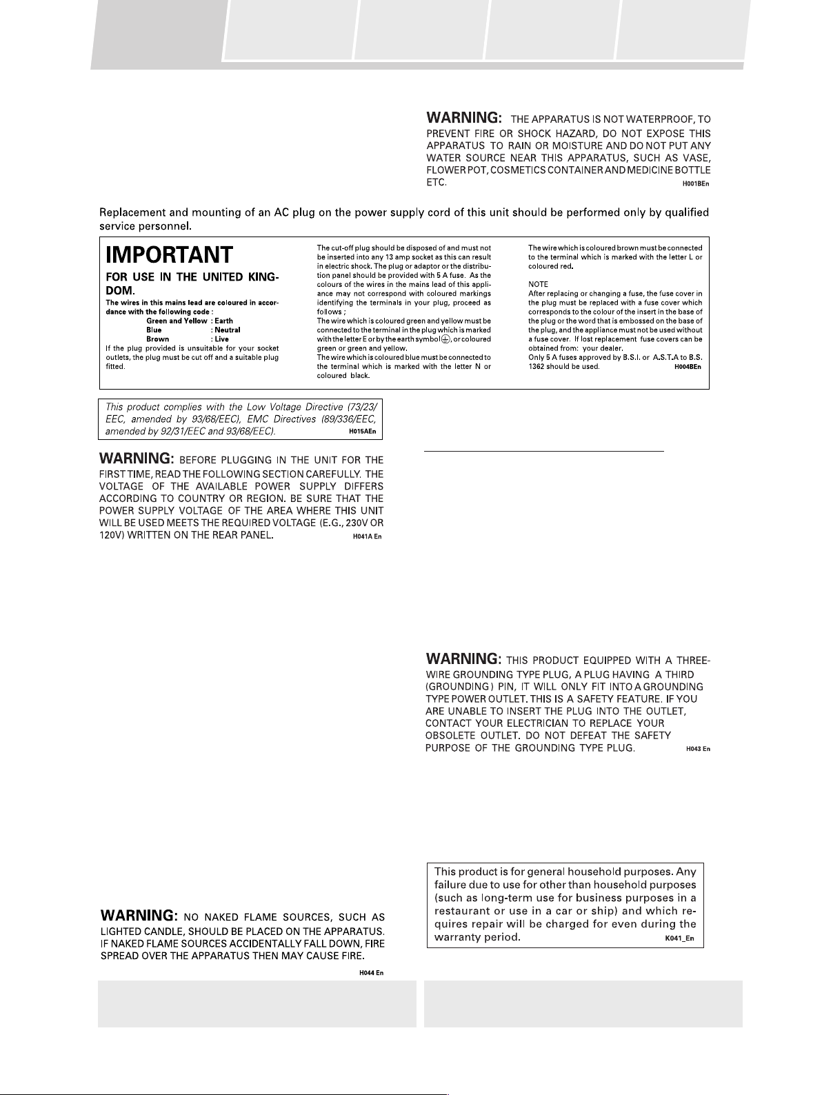
Operating Environment H045 En
Operating environment temperature and humidity:
+5ºC – +35ºC (+41ºF – +95ºF); less than 85%RH (cooling
vents not blocked)
Do not install in locations exposed to strong sunlight,
strong artificial light, high humidity or locations that have
poor ventilation.
INSTALLATION
Note: Reference is made to ISO/IEC Guide 37 [12].
VENTILATION:
÷ When placing this unit with using optional stand or
wall-mount kit, make sure to leave space around the
unit for ventilation to improve heat dispersal at least
3 cm at the rear. If not enough space is provided between the unit and walls or other furniture, heat will
build up inside, interfering with performance and/or
causing malfunctions.
÷ Do not cover the unit with fabric or other covering.
Anything that blocks ventilation will cause the internal temperature to rise, which may lead to breakdown
or fire hazard.
÷ The rear of unit may become hot while in use, please
take care around it.
WARNING: Slot and openings in the cabinet are
provided for ventilation and to ensure reliable operation
of the product and to protect it from overheating, to
prevent fire hazard, the openings should never be
blocked and covered with items, such as newspapers,
table-cloths, curtains, etc. Also do not put the apparatus
on the thick carpet, bed, sofa, or fabric having a thick
pile.
Note: The unit must be installed in such a way that it is
possible to easily disconnect the mains plug.
CAUTION: To prevent injury, this apparatus must be
securely attached to the appropriate Pioneer stands
(model numbers B-PDSP-H, B-PDSP-L or BPDSP-W) in
accordance with the installation instructions. Use with
other apparatus is capable of resulting in instability
causing possible injury.
CAUTION: To disconnect the unit from the mains
supply unplug the mains plug. Install the unit in such a
way that it is easy to disconnect the mains plug in case
of an accident. The mains plug of the unit should be
unplugged from the wall socket when left unused for a
long period of time.
2
Page 3
Safety Precautions Contents Features Confirm All Accessories Specifications
1) Read these instructions.
2) Keep these instructions.
3) Heed all warnings.
4) Follow all instructions.
5) Do not use this apparatus near water.
6) Clean only with dry cloth.
7) Do not block any ventilation openings. Install in accordance with the manufacturer's instructions.
8) Do not install near any heat sources such as radiators, heat registers, stoves, or other apparatus (including amplifiers) that
produce heat.
9) Do not defeat the safety purpose of the polarized or grounding-type plug. A polarized plug has two blades with one wider
than the other. A grounding type plug has two blades and a third grounding prong. The wide blade or the third prong are
provided for your safety. If the provided plug does not fit into your outlet, consult an electrician for replacement of the obsolete
outlet.
10) Protect the power cord from being walked on or pinched particularly at plugs, convenience receptacles, and the point
where they exit from the apparatus.
11) Only use attachments/accessories specified by the manufacturer.
12) Use only with the cart, stand, tripod, bracket, or table specified by the manufacturer, or sold with the apparatus. When
a cart is used, use caution when moving the cart/apparatus combination to avoid injury from tip-over.
Preface
13) Unplug this apparatus during lightning storms or when unused for long periods of time.
14) Refer all servicing to qualified service personnel. Servicing is required when the apparatus has been damaged in any way,
such as power-supply cord or plug is damaged, liquid has been spilled or objects have fallen into the apparatus, the apparatus
has been exposed to rain or moisture, does not operate normally, or has been dropped.
[For U.S. model]
IMPORTANT NOTICE
The serial number for this equipment is located in
the rear panel. Please write this serial number on
your enclosed warranty card and keep it in a secure
area. This is for your security. H006AEn
WARNING:
associated with accessories sold with the product will
expose you to lead, a chemical known to the State of
California and other governmental entities to cause
cancer and birth defects or other reproductive harm.
Wash hands after handling.
Handling the cord on this product or cords
3
Page 4
Safety Precautions Contents Features Confirm All Accessories Specifications
Maintenance of External Surfaces
• Use a polishing cloth or dry cloth to wipe off dust
and dirt.
• When the surfaces are dirty, wipe with a soft
cloth dipped in some neutral cleanser diluted five
or six times with water, and wrung out well, and
then wipe again with a dry cloth. Do not use
furniture wax or cleaners.
• Never use thinners, benzine, insecticide sprays
or other chemicals on or near this unit, since
these will corrode the surfaces.
K023En
Regarding Installation
This product is sold with the understanding that it
will be installed and calibrated only by a trained
service professional with specialized technical
skills. When installing this unit, be sure to consult
a professional installer or your dealer.
Pioneer disclaims all responsibility for any losses
resulting from improper installation, misuse of,
modifications or damage to this unit.
4
Page 5
Safety Precautions Contents Features Confirm All Accessories Specifications
Contents
Preface
Safety Precautions......................................................................................... 2
Features .......................................................................................................... 6
Confirm All Accessories ............................................................................... 8
Specifications ................................................................................................ 9
Parts and their Functions
Front Panel ................................................................................................... 10
Attaching the Front Grill ................................................................. 11
Range of the Remote Control Unit ................................................ 11
Rear Panel .................................................................................................... 12
Turning the Main Power ON/OFF .................................................. 12
About the Input/Output Connectors ............................................. 13
Remote Control Unit ................................................................................... 14
Setting the Basic Infomation on the Remote Control Unit ........ 15
Recharging the Remote Control Unit ........................................... 16
Using the Digital Sound Projector
Using the Remote Control Unit.................................................................. 17
Watching Television ..................................................................................... 21
Watching a DVD .......................................................................................... 22
Using a Pioneer DVD Recorder.................................................................. 23
Recording ......................................................................................... 23
Playback/Editing.............................................................................. 24
Selecting the Audio Mode .......................................................................... 25
Listening to Stereo Sound in Surround Mode ............................. 25
Enhancing Monaural Sources ....................................................... 26
Adjusting the Sound
Changing Surround Sound ........................................................................ 27
Adjusting the Tone ....................................................................................... 31
Calling Up a Room Sound Setting............................................................. 32
Video and Audio Timing Compensations (Lipsync delay)....................... 33
Adjusting Surround Effects ........................................................................ 34
Displaying the Data Screen ........................................................................ 37
Additional Information
Troubleshooting ........................................................................................... 38
Table of Remote Control Unit Menu Displays .......................................... 40
Index .............................................................................................................. 42
Preface
Regarding Installation and Initial Settings
All aspects of installation, connection, and initial surround calibration and setup of the Pioneer Digital Sound
Projector PDSP-1 are to be performed by trained service personnel. Please consult your dealer if you want to change
the installation location, or if major modifications are required to the initial calibration settings.
5
Page 6
Safety Precautions Contents Features Confirm All Accessories Specifications
Features
This digital sound projector is a totally new product unlike conventional home theater systems. It produces multichannel surround sound from a single speaker array, without the need for numerous speaker settings and wiring
hassles.
The following section introduces the features that enable the PDSP-1 to produce its remarkable new sound.
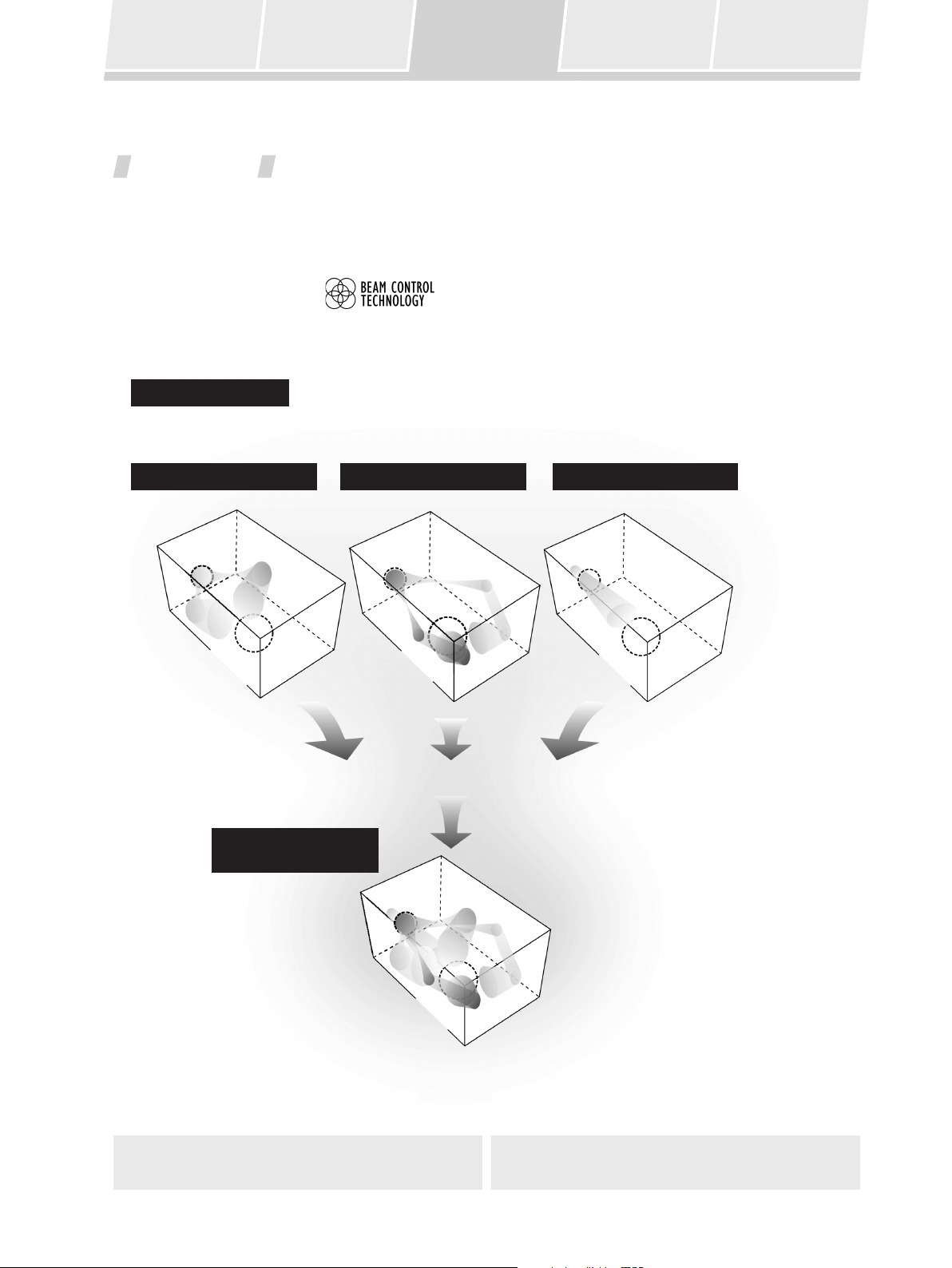
1. Beam control technology
254 individually driven speaker units are arranged in an array on a single panel, and the directionally controlled
audio from this array is radiated in a beam. The sound of each channel radiated in this beam utilizes the
reflectivity of ceiling and walls to produce multi-channel sound.
Audio beam image
The accompanying illustration depicts the way in which the sound beam radiated from the PDSP-1 arrives at the listening
position. In this way, surround sound is produced that totally envelops the listener.
Front left-right channel Rear left-right channel Center channel
PDSP-1
LISTENING
POSITION
Multi-channel
sound field image
PDSP-1
LISTENING
POSITION
PDSP-1
LISTENING
POSITION
PDSP-1
LISTENING
POSITION
6
Page 7
Safety Precautions Contents Features Confirm All Accessories Specifications
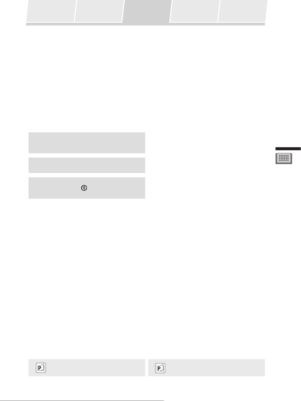
2. Sound settings to match your room’s characteristics
The professional installation technician uses a special metering microphone and computer to set up the unit with
the optimum sound response and characteristics for your room. Since multiple sound settings are possible for any
room, this unit makes it possible for you to call up preset sound environments to change the sound field in
accordance with listening conditions.
3. Equipped with Dolby Digital and Pro Logic II, Digital Theater System (DTS) Decoder
In addition to Dolby Digital – the DVD video standard audio format – this unit also supports Dolby Pro Logic II,
which allows you to play 2-channel sources with multi-channel ambience, and DTS, which produces high sound
quality with low compression ratios and high transmission rates. These features allow you to enjoy multi-channel
movie-theater ambience inside your own home.
Manufactured under license from Dolby Laboratories.
“Dolby”, “Pro Logic”, and the double-D symbol are
trademarks of Dolby Laboratories.
“DTS” and “DTS Digital Surround” are registered
trademarks of Digital Theater Systems, Inc.
Manufactured under license from 1 Ltd. World-wide
patents applied for. The “
Projector” are trademarks of 1 Ltd.
” logo and “Digital Sound
Preface
“Calling Up a Room Sound Setting” P32
“Selecting the Audio Mode”
(Dolby Pro Logic II ) P25
7
Page 8
Safety Precautions Contents Features Confirm All Accessories Specifications
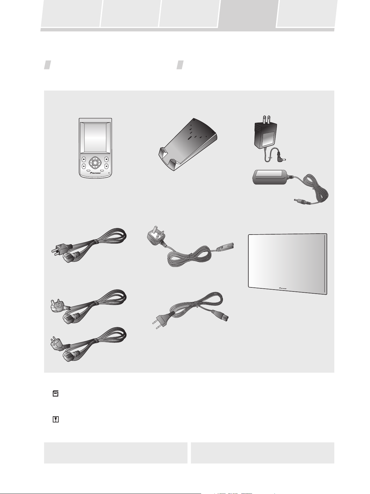
Confirm All Accessories
The digital sound projector is provided with the following accessories:
Remote control unit Recharger AC adapter
(for remote control unit recharger)
For U.S. model
For European model
Power cord
(for main unit)
For U.S. model
For European model (x2)
AC adapter cord (x2)
(furnished with European model only)
Front grille
These operating
instructions
Note:
When disposing of used batteries, please comply with governmental regulations or environmental public
instruction’s rules that apply in your country or area. H048 En
Caution:
Danger of explosion if battery is incorrectly replaced.
Replaced only with the same or equivalent type recommended by the manufacturer.
Discard used batteries according to the manufacturer’s instructions.
8
H027A En
Page 9
Safety Precautions Contents Features Confirm All Accessories Specifications
Specifications
Audio Section Rated output (RMS, 80 Hz – 20 kHz) 2 W x 254 units
Maximum output (80 Hz – 20 kHz, 1 m) 115 dBspl
Tone control: BASS (40 Hz – 320 Hz) ± 12 dB
TREBLE (6.3 kHz – 16 kHz) ± 12 dB
Sub-woofer crossover frequency 40 Hz – 200 Hz
Output level / impedance 1.0 Vp-p / 100 Ω
Input sensitivity / impedance 150 mVp-p / 47 kΩ
Speaker response 80 Hz – 20 kHz, ± 3dB
Video Section Video connectors (level / impedance) 1.0 Vp-p / 75 Ω
S/N ratio 55 dB
Frequency response (output connectors) 5 Hz – 10 MHz, –3 dB
Power Section Power source AC 120 V, 60 Hz (U.S. model)
AC 100 – 240 V, 50/60 Hz (European model)
Power consumption 750 W
Power consumption in standby mode 3 W
External Dimensions 963 (W) x 640 (H) x 146 (D) mm
(37-15/16 (W) x 25-4/16 (H) x 5-12/16(D) in.)
Weight of Main Unit 50 kg (110 lb 4 oz) (including front grille)
Accessories Remote control unit
Recharger
AC Adapter (AC 120 V, 50/60 Hz, rated voltage 6 V) (U.S. model)
AC Adapter (AC 100 – 240 V, 50/60 Hz, rated voltage 6 V) (European model)
AC adapter cord (furnished with European model only)
Power cord
Front grille
Operating Instructions
Preface
Note:
Specifications and the design are subject to possible modifications without notice, due to improvements.
9
Page 10
Front Panel
Rear Panel
Remote Control Unit
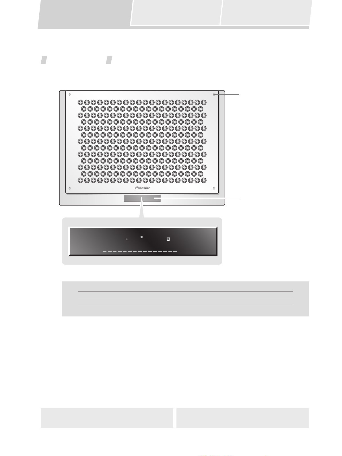
Front Panel
Indicators for power and volume level, and the remote control unit sensor are located on the lower part of the panel.
Front grille attachment tabs
(4)
POWER ON
STANDBY
VOLUME LEVEL
Display Meaning/Operation
POWER ON (Blue) Lights when power is turned ON
STANDBY (Red) Lights in power standby mode
VOLUME LEVEL Indicates sound volume
Display/remote control unit
sensor
10
Page 11
Front Panel
Rear Panel
Remote Control Unit
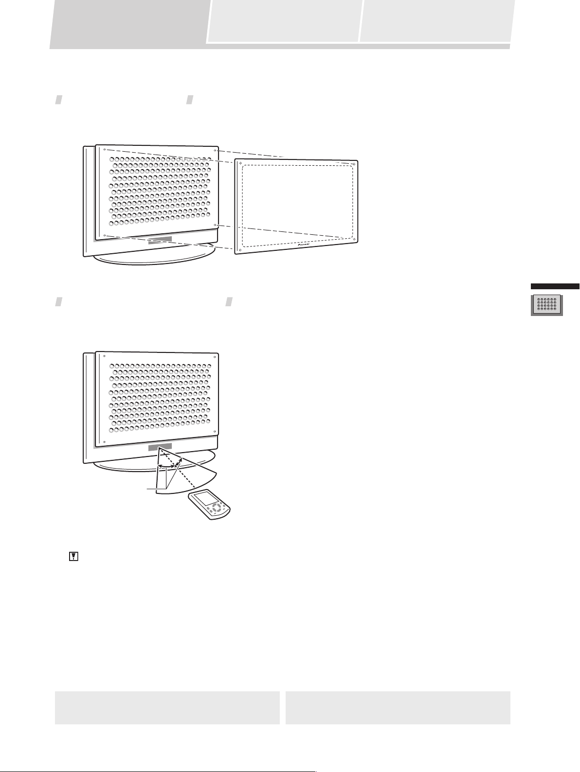
Attaching the Front Grille
Align the grille with the four attachment tabs on the front panel, then push into place.
Range of the Remote Control Unit
Operate the remote control unit while pointing it toward the Digital Sound Projector’s remote control sensor within
the range shown.
Parts and their Functions
7m
30°
Caution:
Do not expose the remote control sensor to direct sunlight or other strong light sources.
11
Page 12
Front Panel Remote Control Unit
Rear Panel
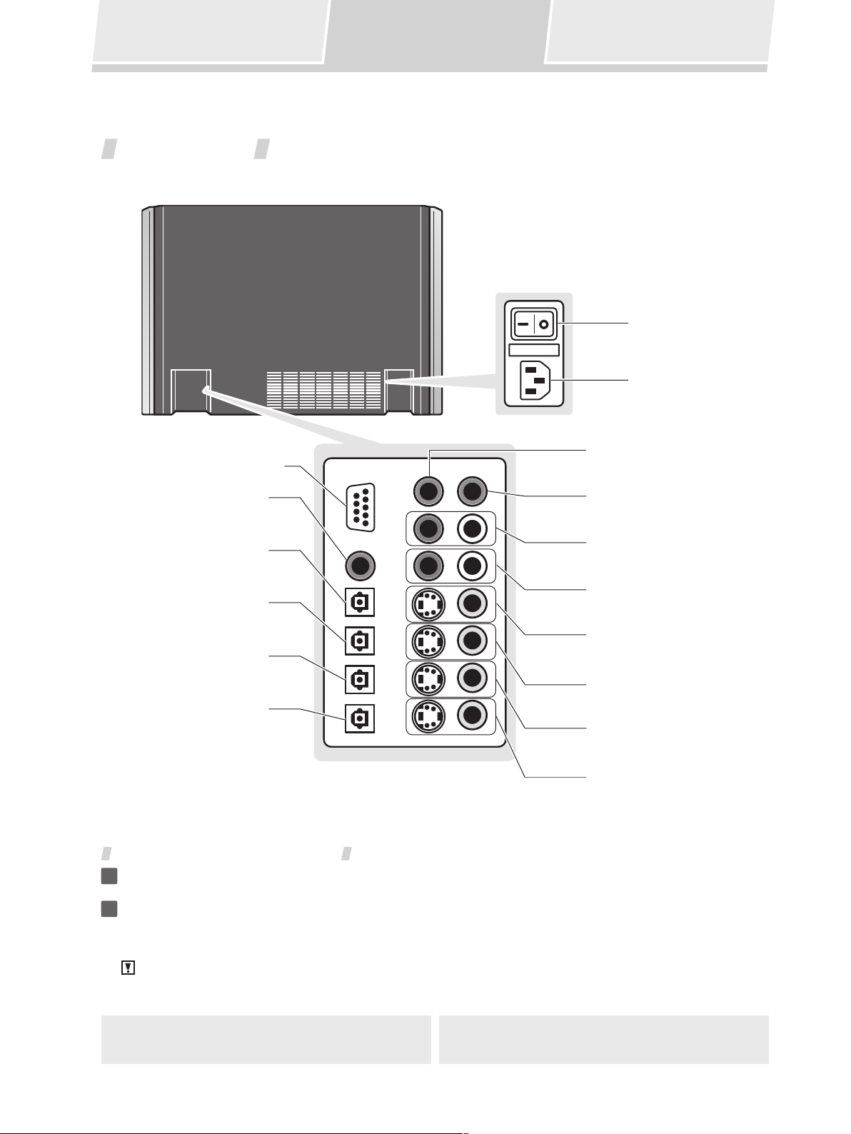
Rear Panel
The main power switch, power cord socket, and input/output connectors are located on the rear panel.
Main power switch
Power cord socket
SUB WOOFER 1 OUTPUT
RS-232C connector
(used by installation technician)
INPUT 1 COAXIAL
(digital audio input)
(sub-woofer output 1)
SUB WOOFER 2 OUTPUT
(sub-woofer output 2)
INPUT 2 OPTICAL
(digital audio input)
INPUT 3 OPTICAL
(digital audio input)
INPUT 4 OPTICAL
(digital audio input)
OUTPUT OPTICAL
(digital audio output)
INPUT 5
(analog audio inputs)
INPUT 2
(analog audio inputs)
INPUT 2
(video inputs)
INPUT 5
(video inputs)
INPUT 4
(video inputs)
MONITOR OUTPUT
(video outputs)
Turning the Main Power ON/OFF
Connect the supplied power cord to the rear panel power cord socket, and then insert the plug
1
in a household power outlet.
Turn the main power ON/OFF by setting the main power switch to the [–] (ON) or [°] (OFF) sides.
2
Caution:
Do not use any power cord other than the one supplied.
12
Page 13
Front Panel Remote Control Unit
Rear Panel
About the Input/Output Connectors
Caution:
Before making or changing the connections, switch off the power and disconnect the power cord
from the AC outlet.
Audio output (OUTPUT OPTICAL connector)
Use to connect MD recorders, CD recorders and other digital recording components. These connectors
output the digital signals from inputs 1 to 4.
Video outputs (MONITOR OUTPUT connectors)
Use to connect a television monitor or other video component.
Note:
The selection of S or composite connectors should match the selection on the signal input side. (If an S2
video input is used, use the S output connector; if the input is composite, use the composite output
connector as well).
SUB WOOFER OUTPUT connectors
Up to two sub-woofers can be connected.
Note:
Sub-woofers reproduce very low-frequency sound; coupled with the LFE (Low-Frequency Effect) channels
encoded in Dolby digital and DTS audio sources, these speakers produce sounds effects which heighten
the impact and realism of motion picture sound tracks and other sources.
Parts and their Functions
INPUT 1 – 5 connectors
The digital sound projector is equipped with 5 input connector systems which can be combined in the ways
shown below. The various inputs can be selected by using the to or buttons on the remote
control unit.
INPUT Audio Connector Video Connector
1 Coaxial digital – (no video)
2 Optical digital/analog S / Composite
3 Optical digital – (no video)
4 Optical digital S / Composite
5 Analog S / Composite
Note:
Input 2 provides for automatic sensing of digital and analog sources. In the event that both digital and
analog signals are simultaneously input to the digital sound projector, the digital signal is given priority.
13
Page 14
Front Panel
Rear Panel
Remote Control Unit
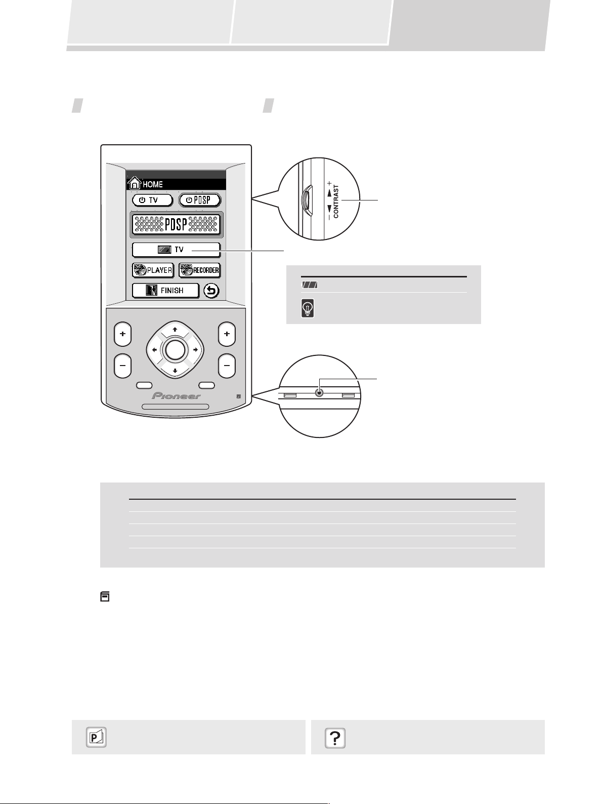
Remote Control Unit
The touch panel appears when the LCD touch panel is touched or a remote control unit button (hard key) is pressed.
Side panel
CONTRAST
(adjusts touch panel
display contrast)
LCD touch panel
Display Meaning/Operation
Rechargeable battery status
Touch panel backlight
CHANNEL VOLUME
MENU MUTE
ENTER
Bottom panel
Terminal used by
installation technician
HOME AV CONTROLLER
About the Remote Control Unit Buttons (hard keys)
Button Meaning/Operation
CHANNEL Use to select channels
MENU Use to turn the menu display ON/OFF
ENTER Use to select and input menu display operations
VOLUME Use to adjust sound volume level
MUTE Use to temporarily turn off sound
Note:
The remote control unit buttons (hard keys) differ in function depending on which component has been
selected on the touch panel. For details, see the section “Table of Remote Control Unit Menu Displays” (P40).
“Using the Remote Control Unit”
“Component Operation Menu Display” P17
“Touch panel menus don’t change”
“Resetting the Remote Control Unit” P39
14
Page 15

Front Panel
Rear Panel
Remote Control Unit
Setting the Basic Information on the Remote Control Unit
Seven items, including current time display and beep volume can be set on the remote control unit.
Set the touch panel to the HOME menu.
1
If the touch panel shows any display other than the HOME menu, press the mark at the bottom.
HOME menu
Press the “ ” mark at the top left.
2
The setting menu will be displayed.
Use the arrows on the touch panel to switch between the two menu screens.
SETUP
CLOCK DISPLAY: AM/PM
CLOCK SETTING
BEEP:
Follow the instructions on the screen to change the items you want.
3
SETUP
LCD TIMEOUT
BACKLIGHT TIMEOUT
CALIBRATE
Item Select Setting Contents
CLOCK DISPLAY 12-hour or 24-hour display Type of clock display
CLOCK SETTING Year/Month/Day/Hour/Minute Date and Time
BEEP
/ /OFF Sound volume of beep when touch panel is
pressed
LCD TIMEOUT 20-120 seconds Touch panel OFF time (if no remote control unit
operation is performed during the set time, the
display will automatically turn off to conserve
power).
BACKLIGHT TIMEOUT
20-120 seconds How long the display illumination remains on
when is pressed.
CALIBRATE Fine adjustment of display screen position
Parts and their Functions
Once the settings are completed, press or .
4
The screen returns to the HOME menu.
15
Page 16

Front Panel
Rear Panel
Remote Control Unit
Recharging the Remote Control Unit
Connect the accessory AC adapter to the recharger and a household AC outlet.
1
Note:
Illustration depicts U.S. model.
Place the remote control unit on the recharger, aligning the indents on the remote control unit
2
with the tabs on the recharger.
Note:
During recharging, the indicator shown below will appear on the upper right corner of the display.
Recharging indicator
Caution:
Do not use AC adapters other than the one supplied.
“Can’t recharge remote control unit” P39
16
Page 17

Using the Remote
Control Unit
Watching Television Watching a DVD
Using a Pioneer DVD
Recorder
Selecting the Audio
Mode
Using the Remote Control Unit
The remote control unit’s buttons and touch panel can be used to control components connected to the digital sound
projector.
Component Operation Menu Display
When using the remote control unit to control the digital sound projector and video components, menu displays are
provided for the current component being used. The remote control unit has the following component menu displays:
Operation Menu Meaning/Contents
HOME HOME menu
PDSP Operate Digital Sound Projector
TV Operate television monitor
DVD PLAYER Operate DVD player
DVD RECORDER Playback/edit on Pioneer DVD recorder
DVD RECORDER Record on Pioneer DVD recorder
Note:
The currently selected menu screen can be confirmed by looking in the upper left corner of the touch panel.
Current menu screen indicator
Using the Digital Sound Projector
“About the Remote Control Unit Buttons (hard
keys)” P14
“Table of Remote Control Unit Menu Displays”
P40
17
Page 18

Using the Remote
Control Unit
Watching Television Watching a DVD
Using a Pioneer DVD
Recorder
Selecting the Audio
Mode
About the HOME Menu
This is the basic touch panel menu. From this menu screen, the operating menus for various connected components
can be selected.
Display Meaning/Operation
Turns television power ON/OFF
Turns digital sound projector power ON/OFF
Selects the digital sound projector operating menu ( P19)
Selects the TV operating menu ( P21)
Selects the DVD player operating menu ( P22)
Selects the DVD recorder operating menu ( P24)
Turns off power to all connected components
Returns to previous menu
“Setting the Basic Information on the Remote
Control Unit” P15
18
Page 19

Using the Remote
Control Unit
Watching Television Watching a DVD
Using a Pioneer DVD
Recorder
Selecting the Audio
Mode
About the PDSP (digital sound projector) menu
When using the digital sound projector with other components, this menu screen is used to select operation of other
components. This menu is also used to select signal inputs (input 1 to 5).
Display Meaning/Operation
Turns digital sound projector power ON/OFF
Turns television power ON/OFF
– Selects input 1 to 5
Alternates between inputs 1 to 5
Selects the TV operating menu ( P21)
Selects the DVD player operating menu ( P22)
Selects the DVD recorder operating menu ( P24)
Returns to previous menu
Returns to HOME menu
Using the Digital Sound Projector
“INPUT 1 – 5 connectors” P13
19
Page 20

Using the Remote
Control Unit
Watching Television Watching a DVD
Using a Pioneer DVD
Recorder
Selecting the Audio
Mode
Operating Menus for Other Components
Use the operating menus for connected components (DVD player, television, etc.) according to the typical functions
and operations of the respective component. Other operating menu items appear as follows:
Example:
Television Operating Menu
1/2
2/2
Display Meaning/Operation
Selects the PDSP menu ( P19)
Selects the recording menu for DVD recorder ( P23)
Returns to HOME menu
Returns to previous menu
Changes between the menu screens (1/2, 2/2)
20
Page 21

Using the Remote
Control Unit
Watching Television Watching a DVD
Watching Television
Use this menu to operate a connected television.
1
Turn on power to digital sound projector.
2
Turn on power to television.
Using a Pioneer DVD
Recorder
Selecting the Audio
Mode
3
Select input connected to television sound.
4
Change to television operating menu.
TV VOLUME
5
Reduce television’s built-in speakers so as not to affect sound from digital
sound projector.
To next operation.
6
The lower two menu screens are used to operate the television.
7
Use the arrows on the touch panel to alternate between the two
menus.
Television Operating Menus (2 screens)
1/2 2/2
1/2
– ,
Using the Digital Sound Projector
2/2
Note:
When is pressed in step 1, the television operating screen shown in 7 appears, and the
television can be operated without using the digital sound projector. Note that in this case, the
does not appear on the 2/2 menu, with the result that the remote control unit’s volume button (hard key) must
be used to adjust the television sound volume.
“About the Remote Control Unit Buttons (hard
keys)” P14
“Table of Remote Control Unit Menu Displays”
P40
21
item
Page 22

Using the Remote
Control Unit
Watching Television Watching a DVD
Watching a DVD
Use this menu to operate a connected DVD player.
1
Turn on the power to the digital sound projector.
2
Turn on the power to the television monitor.
3
Set television input to digital sound projector.
Using a Pioneer DVD
Recorder
Selecting the Audio
Mode
4
Select the input connected to the DVD player.
5
Change to DVD player operating menu.
The accompanying three menus are used to operate the DVD
6
player.
Use the arrows on the touch panel to change between the menu
screens.
DVD Player Operating Menus (3 screens)
1/3 2/3
1/3 2/3 3/3
– ,
3/3
Notes:
If a Pioneer DVD player is connected, the DVD player’s power will turn on in step 5.
If is pressed in step 1, the DVD player operating menus shown in step 6 will appear, and it will be
possible to operate the DVD player without using the digital sound projector.
“INPUT 1 – 5 connectors” P13
22
Page 23

Using the Remote
Control Unit
Watching Television Watching a DVD
Using a Pioneer DVD
Recorder
Using a Pioneer DVD Recorder
Use this menu to operate a connected Pioneer DVD Recorder.
Recording
To record the program currently playing on the television, follow the steps listed below.
Steps 1 – 6 are the same as steps 1 – 6 on P21 “Watching Television”.
1/2
7
Change to recording menu on DVD recorder.
DVD Recorder: Recording Menu (2 screens)
Selecting the Audio
Mode
Using the Digital Sound Projector
1/2
2/2
1/2
2/2
Perform recording operations on menu 1/2 at left.
8
HDD/DVD: Selects type of disk for recording (HDD/DVD)
DISPLAY: Displays disc information
REC MODE: Selects recording mode FINE/SP/LP/EP
AUDIO: Selects audio channel for recording (main/sub)
REC: Starts recording
STOP REC: Stops recording
Note:
Press on the first screen to change to menu screen 2/2; this menu
allows playback and confirmation of recorded contents.
“Watching Television” P21
23
Page 24

Using the Remote
Control Unit
Playback/Editing
Watching Television Watching a DVD
1
Change to digital sound projector menu.
Using a Pioneer DVD
Recorder
Selecting the Audio
Mode
2
Turn on TV power.
3
Set television video input to digital surround projector.
4
5
6
DVD Recorder Operating Menus (4 screens)
– ,
Select input connected to DVD recorder.
Change to DVD recorder operation menu.
The following four menus are used to operate the DVD recorder.
Use the arrows on the touch panel to change between the menu
screens.
1/4
1/4
2/4 3/4 4/4
2/4 3/4
4/4
Note:
When is pressed in step 1, the DVD recorder operating menu shown in 6 appears, and the DVD
recorder can be operated without using the digital sound projector.
Caution:
Some operations may not be possible, depending on the specific model of Pioneer DVD Recorder connected.
24
Page 25

Using the Remote
Control Unit
Watching Television Watching a DVD
Using a Pioneer DVD
Recorder
Selecting the Audio
Selecting the Audio Mode
Listening to Stereo Sound in Surround Mode
Stereo broadcasts, CD playback and other 2-channel sounds can be enjoyed in surround sound mode.
Set the touch panel to the PDSP menu.
1
From the HOME menu, press ; from other menus, press .
PDSP menu
Mode
Press .
2
The television screen will display the audio mode.
Each time the button is pressed, the audio mode will change in the following order.
PLII Movie: Pro Logic II Movie
This mode is designed for use with film soundtracks, and allows
PLII Movie
PLII Music
Pro Logic
Stereo
Notes:
If is pressed during playback of Dolby Digital and other surround sources, the following message will be
displayed:
actors’ dialogue to be heard from the most natural direction.
PLII Music: Pro Logic II Music
This mode is designed for use with music sources. The surround
effect recreates the ambience experienced in live performances.
Pro Logic:
The Pro Logic Mode is generally designed for general use with
movie soundtracks. The rear channel track is heard in monaural
surround.
Stereo:
The stereo mode is a two-channel mode; when this mode is
selected, even multi-channel sources are played back in two
channels, and heard from the front right and left.
Using the Digital Sound Projector
Dolby Digital
If is pressed in step 2, the unit will change to stereo mode.
“Fine Tuning the PLII Music Mode” P35
25
Page 26

Using the Remote
Control Unit
Watching Television Watching a DVD
Using a Pioneer DVD
Recorder
Selecting the Audio
Mode
Enhancing Monaural Sources
When listening to older movies and CDs, and other sources recorded in monaural sound, the sound will seem more
natural when heard from the center channel alone, rather from the front two channels (right and left).
Set the touch panel to the PDSP menu.
1
From the HOME menu, press ; from other operation menus, press .
Press
2
The “Mono” indicator will appear on the television screen.
Each time the button is pressed, the monaural mode alternates between ON and OFF.
Mono
26
Page 27

Changing
Surround Sound
Caution:
When adjusting the digital sound projector’s sound, the menu screen is displayed on the connected television
monitor. To see the display, turn on the television’s power and set the television’s video input to the digital
sound projector.
Note:
When adjusting the digital sound projector’s sound, use the following buttons (hard keys) of the remote
control unit:
Button Name Function
Adjusting the Tone
Calling Up a Room
Sound Setting
MENU Open/Close the menu screen
Move cursor / select items and numbers
Video and Audio
Timing
Compensations
Adjusting
Surround Effects
Displaying the
Data Screen
ENTER Finalize settings
Changing Surround Sound
You can adjust each channel’s volume/balance while listening to the actual sound, as well as adjusting the subwoofer and other options.
Test Signal
A test signal can be used to adjust the output level of each channel.
Use the touch panel to select the PDSP menu.
1
From the HOME menu, press ; from other menus, press .
Press the MENU button.
2
The following “System Setup” menu appears.
System Setup
1 Surround Setup
2 All Ch Tone Control
3 Recall Memory
4 Lipsync delay
5 Stereo Mode
Adjusting the Sound
“Digital sound projector menu screens don’t
appear” P38
“Changing Each Channel’s Output Level” P29
27
Page 28

Changing
Surround Sound
Using the buttons, select “Surround Setup”, and press the ENTER button.
3
The following screen appears:
Adjusting the Tone
Calling Up a Room
Sound Setting
Surround Setup
1 Left 0.0dB
Video and Audio
Timing
Compensations
Front left channel
Front right channel
Adjusting
Surround Effects
2 Right 0.0dB
3 Surround L 0.0dB
Rear left channel
4 Surround R 0.0dB
5 Center 0.0dB
6 Aux Center Mute
7 Bass Management
Rear right channel
Center channel
8 Noise Source off
Note:
“Aux Center” is an additional center channel. To use the “Aux Center” channel, a special dedicated setting is
required; consult your installation service personnel.
Displaying the
Data Screen
Using the buttons, select “Noise Source”, and press the ENTER button.
4
The following screen appears:
Noise Source
1 Off
2 Left
3 Right
4 Surround L
5 Surround R
6 Center
7 Aux Center
8 LFE
Using the buttons, select the channel, and press the ENTER button.
5
The test signal will be produced from the selected channel.
“Sub Woofer / Bass Management” P30
28
Page 29

Changing
Surround Sound
Adjusting the Tone
Calling Up a Room
Sound Setting
Video and Audio
Timing
Compensations
Adjusting
Surround Effects
Changing Each Channel’s Output Level
- 3 (Same as steps 1 - 3 on P27, “Test Signal”)
1
The following screen appears:
Front left channel
Surround Setup
1 Left 0.0dB
Front right channel
2 Right 0.0dB
3 Surround L 0.0dB
Rear left channel
4 Surround R 0.0dB
5 Center 0.0dB
6 Aux Center Mute
7 Bass Management
Rear right channel
Center channel
8 Noise Source off
Using the buttons, select the desired channel, then press the ENTER button.
4
The following screen appears:
Displaying the
Data Screen
Left
to edit
Press ENTER or MENU to exit
Level
0.0dB
Using the buttons, adjust the output level as desired, then press the ENTER button.
5
Adjust the output level while listening to the test signal.
Setting range: 0.0 dB – 12.0 dB
Note:
When you’re finished, you can press the MENU button repeatedly to return to previous screens.
Adjusting the Sound
29
Page 30

Changing
Surround Sound
Adjusting the Tone
Calling Up a Room
Sound Setting
Video and Audio
Timing
Compensations
Adjusting
Surround Effects
Sub Woofer / Bass Management
This menu allows you to set the unit for a sub-woofer, and LFE channel ON/OFF.
- 3 (Same as steps 1 - 3 on P27, “Test Signal”)
1
Using the buttons, select “Bass Management”, and press the ENTER button.
4
The following screen appears:
Bass Management
1 Sub Woofer Yes
2 LFE Level 0.0dB
LFE channel output level
Displaying the
Data Screen
Notes:
LFE means “Low Frequency Effect”.
If “Sub Woofer” is set to “Yes”, use the buttons to select “LFE level”, then use the buttons to adjust
the output level.
Setting range: 0.0 dB – 12.0 dB
Using the buttons, select “Sub Woofer”, then press the ENTER button.
5
The following screen appears:
Sub Woofer: No
(LFE will not be output from any channel)
Sub Woofer Menu
1 No
2 No/LFE to panel
3 Yes
Using the buttons, select either “No,” “No/LFE to panel,” or “Yes,” then press the ENTER
6
button.
Sub Woofer: No/LFE to panel
(LFE is output from digital sound projector)
Sub Woofer: Yes
(LFE is output to Sub Woofer)
Note:
When you’re finished, you can press the MENU button repeatedly to return to previous screens.
“SUB WOOFER OUTPUT connectors” P13
30
Page 31

Changing
Surround Sound
Adjusting the Tone
Calling Up a Room
Sound Setting
Video and Audio
Timing
Compensations
Adjusting
Surround Effects
Adjusting the Tone
You can adjust the overall tone for all audio channels.
Use the touch panel to select the PDSP menu.
1
From the HOME menu press ; from other menus, press .
Press the MENU button.
2
The “System Setup” menu screen appears.
Using the buttons, select “All Ch Tone Control”, and press the ENTER button.
3
The following screen appears:
All Ch Tone Control
1 Bass Level 0dB
2 Treble Level 0dB
Bass
Treble
Displaying the
Data Screen
Adjusting the Sound
Using the buttons, select either “Bass Level” or “Treble Level”, then press the ENTER
4
button.
The following screen appears:
All Ch
to edit
Press ENTER or MENU to exit
0dB
– Bass +
0
Using the buttons, adjust the tone level as desired, then press the ENTER button.
5
Setting range: –12 dB – +12 dB
Note:
When you’re finished, you can press the MENU button repeatedly to return to previous screens.
31
Page 32

Changing
Surround Sound
Adjusting the Tone
Calling Up a Room
Sound Setting
Video and Audio
Timing
Compensations
Adjusting
Surround Effects
Displaying the
Data Screen
Calling Up a Room Sound Setting
Multiple sound settings can be recorded in accordance with measured room characteristics. Select the setting that
produces the optimum listening environment.
Use the touch panel to select the PDSP menu.
1
From the HOME menu press ; from other menus, press .
Press the MENU button.
2
The “System Setup” menu display appears.
Using the buttons, select “Recall Memory”, then press the ENTER button.
3
The following screen appears.
Recall from..
1 Memory 1
2 Memory 2
3 Memory 3
4 Memory 4
5 Memory 5
6 Memory 6
7 Memory 7
8 Memory 8
Using the buttons, select the desired sound setting, then press the ENTER button.
4
Notes:
When you’re finished, you can press the MENU button repeatedly to return to previous screens.
A maximum of eight room sound settings can be stored in memory. Consult your installation service
personnel regarding the settings that will work best with your room.
32
Page 33

Changing
Surround Sound
Adjusting the Tone
Calling Up a Room
Sound Setting
Video and Audio
Timing
Compensations
Adjusting
Surround Effects
Displaying the
Data Screen
Video and Audio Timing Compensations (Lipsync
delay)
The video playback from some components may appear somewhat delayed from the audio channel. If actors’ mouth
movements appear to be out of sync with the audible soundtrack, use this adjustment to delay (compensate) the
audio timing.
Use the touch panel to select the PDSP menu.
1
From the HOME menu press ; from other menus, press .
Press the MENU button.
2
The “System Setup” menu appears.
Using the buttons, select “Lipsync delay”, then press the ENTER button.
3
The following screen appears:
Lipsync delay
to edit
Press ENTER or MENU to exit
Delay 0ms
Using the buttons, adjust the amount of delay as desired, then press the ENTER button.
4
Perform this adjustment while confirming the actual video-audio timing.
Notes:
The maximum adjustment value will be less than 106 ms, as a result of the initial room setting made by the
service personnel.
When you’re finished, you can press the MENU button repeatedly to return to previous screens.
Adjusting the Sound
33
Page 34

Changing
Surround Sound
Adjusting the Tone
Calling Up a Room
Sound Setting
Video and Audio
Timing
Compensations
Adjusting
Surround Effects
Displaying the
Data Screen
Adjusting Surround Effects
Narrowing the audio width of the front right-left channels (Image width)
As a characteristic of the digital sound projector, when the room’s right and left walls are far apart, some playback
sources may sound overly separated.
This function allows you to adjust the width of the sound image to a narrow perspective, thus producing a more
natural sound image.
Use the touch panel to select the PDSP menu.
1
From the HOME menu press ; from other menus, press .
Press the MENU button.
2
The “System Setup” menu screen appears.
Using the buttons, select “Stereo Mode”, then press the ENTER button.
3
The following screen appears:
Stereo Mode Menu
1 Image width On
2 Image width value 1.00
3 PLII Mode PLII Movie
Using the buttons, select “Image width”, then use the buttons to select “On”.
4
Using the buttons, select “Image width value”, then use the buttons to adjust the
5
value as desired; when done, press the ENTER button.
Setting range: 0.00 – 1.00 (1.00 when setting is OFF)
Notes:
Setting value 1.00 is for stereo sound (sound width spread to front right-left).
Setting value 0.00 is monaural (sound spread is narrowed and produced only from the center channel).
When you’re finished, you can press the MENU button repeatedly to return to previous screens.
“Fine Tuning the PLII Music Mode” P35
34
Page 35

Changing
Surround Sound
Adjusting the Tone
Calling Up a Room
Sound Setting
Video and Audio
Timing
Compensations
Adjusting
Surround Effects
Displaying the
Data Screen
Fine Tuning the PLII Music Mode
When listening to a two-channel source in surround sound using the PLII Music mode, you can fine tune the effect
from the “Stereo Mode Menu”.
Use the touch panel to select the PDSP menu.
1
From the HOME menu press ; from other menus, press .
Press the MENU button.
2
The “System Setup” menu screen appears.
Using the buttons, select “Stereo Mode”, then press the ENTER button.
3
The following screen appears:
Stereo Mode Menu
1 Image width On
2 Image width value 1.00
3 PLII Mode PLII Movie
Adjusting the Sound
Using the buttons, select “PLII Mode”, then press the ENTER button.
4
The following screen appears:
PLII Mode
1 PLII Off
2 Movie
3 Music
4 Pro Logic
“Selecting the Audio Mode”
(Dolby Pro Logic II) P25
35
Page 36

Changing
Surround Sound
Using the buttons, select “Music”, then press the ENTER button.
5
Using the buttons, select “Panorama”, “Center width”, or “Dimension”, then use the
6
Adjusting the Tone
Calling Up a Room
Sound Setting
Video and Audio
Timing
Compensations
Adjusting
Surround Effects
buttons to set the effect as desired.
Stereo Mode Menu
1 Image width On
2 Image width value 1.00
3 PLII Mode PLII Music
4 Panorama Off
5 Center width 0
6 Dimension 3
Displaying the
Data Screen
Display Setting Effect
Panorama On/Off The front sound image expands toward the rear
as well, enveloping the listener in surround
sound.
Center width 0-7 Adjusts the audible width of the center channel
(0 means sound is produced from the center
channel; as the numerical value rises, the sound
width expands, until at 7 the sound is produced
from the front right-left channels).
Dimension 0-6 Shifts the surround effect balance between front
and back (0 means sound is toward the front; as
the numerical value increases, the balance shifts
toward the back, until at 6 it is produced from the
rear channel).
Note:
When you’re finished, you can press the MENU button repeatedly to return to previous screens.
36
Page 37

Changing
Surround Sound
Adjusting the Tone
Calling Up a Room
Sound Setting
Video and Audio
Timing
Compensations
Adjusting
Surround Effects
Displaying the
Data Screen
Displaying the Data Screen
Use this function to confirm information about the currently playing audio and video source, and room sound
settings.
Use the touch panel to select the PDSP menu.
1
From the HOME menu press ; from other menus, press .
Press the ENTER button.
2
The “Status” menu screen appears as shown below.
Status
Source Input 2 D
Memory 1
Mode PLII Movie
Width 1.00
Item Contents Display Example
Source Input/Signal type Input 1-5, 2D (digital), 2A (analog)
Memory Preset sound setting 1-8, * (when a change has occurred to the called-
Mode Audio mode type PLII Movie, PLII Music, Pro Logic, Stereo, Mono
Width Image width setting 0.00-1.00 (image width setting value), Off
After confirming the data, press the ENTER button.
3
The “Status” menu screen disappears.
Adjusting the Sound
up sound setting)
“INPUT 1 – 5 connectors” P13
“Selecting the Audio Mode”
(Dolby Pro Logic II) P25
“Calling Up a Room Sound Setting”
(Memory 1-8) P32
“Adjusting Surround Effects”
(Image width) P34
37
Page 38

Troubleshooting
Table of Remote Control Unit Menu
Displays
Index
Troubleshooting
Many malfunctions can be the result of operating errors. If you experience trouble with the digital sound projector,
use this troubleshooting guide together with thorough checks of the other components in your system. If the problem
is not corrected after doing so, consult your authorized service center.
Sound
Problems?
No sound
Use the remote control unit’s PDSP menu to check INPUTs 1-5, and
confirm you have selected the correct input.
Check the front panel VOLUME LEVEL indicator to confirm whether the
MUTE button has been pressed, or if the sound volume has been set to its
minimum setting.
Confirm that the digital sound projector’s main power is turned ON and
that the front panel’s POWER ON indicator (Blue) is lighted.
Sound has a poor surround effect
Confirm whether the audio mode has been set to “Mono” for monaural
sound.
Confirm whether the audio mode has been set to “Stereo” for stereo sound.
Check the playback source to confirm that it is a multi-channel source.
Sound has poor balance
Confirm that the proper room sound setting has been chosen.
If the digital sound projector has been physically moved, or if the furniture
in the room been significantly rearranged or changed, consult your
installation technician to have the digital sound projector recalibrated for
the new room environment.
No sound from the connected sub-woofer, or sound volume is too low
Confirm whether the sub-woofer’s output level has been set low.
Recording isn’t possible on the connected components
If the playback source is a digital signal, it may be protected with a
copyguard function, in which case it cannot be recorded. In this case, use
an analog connection between the playback component and recording
component, and record the source in analog mode.
P19
P10
P10
P26
P25
P32
P30
Video
Problems?
Digital sound projector menu screens don’t appear
Confirm that the proper video input has been selected on the television
monitor.
No image is visible on the connected TV monitor.
Confirm that the proper video input has been selected on the television
monitor.
38
Page 39

Troubleshooting
R
E
S
E
T
RESETR
E
S
E
T
Problems
with Use or
Operation?
Table of Remote Control Unit Menu
Displays
Can’t recharge remote control unit
Check the recharge indicator in the upper right corner of the remote
control unit’s touch panel to confirm whether the remote control unit is
sitting on the recharger and recharging correctly.
If the remote control unit’s battery won’t hold a sufficient charge to allow
use of the remote control unit even after proper recharging, the unit’s
Lithium-ion battery may require replacing. In this event, consult your
authorized Pioneer service center. The remote control unit’s Lithium-ion
battery cannot be purchased at any location other than an authorized
Pioneer service center.
Remote control unit doesn’t work
Check that the main power switch is turned on, the power cord is con-
nected securely, and the front panel’s POWER ON (Blue) or STANDBY
(Red) indicator is lighted.
Check the remote control unit’s remaining charge indicator to confirm that
the remote control unit’s battery is properly recharged.
You may be using the remote control too far from the sensor (Try moving
closer to the digital sound projector).
Remote operation may become unreliable if direct sunlight, a fluorescent
lamp, or other strong light source is striking the remote control sensor on
the front panel.
Index
P16
P10
P14
P11
Additional Information
Remote control unit doesn’t operate connected Pioneer DVD recorder
Depending on the model, some functions may not be supported.
Touch panel menus don’t change
If the remote control menu screens do not change, try using the following
procedure to reset the remote control unit. Resetting the remote control
unit will not erase recorded settings.
If the unit does not operate normally due to external effects (such as
static electricity)
Disconnect the power plug from the outlet and insert again to return to
normal operating conditions.
Resetting the Remote Control Unit
Use a Phillips screwdriver
1
to remove the screw on
the back panel of the
remote control unit.
Remove the panel.
2
Use a narrow pointed
3
object to press the RESET
button.
39
Page 40

Troubleshooting
1/2
1/2
2/2
1/3
1/4 2/4 3/4 4/4
2/3
3/3
2/2
CHANNEL
MENU
ENTER
VOLUME, MUTE
[TV] Channel select
Menu
[PDSP]
Enter
[TV] Volume setting,
Mute
HOME Menu
CHANNEL
MENU
ENTER
VOLUME, MUTE
TV Menus 1/2-2/2
DVD RECORDER Menus 1/2-2/2
CHANNEL
MENU
ENTER
VOLUME, MUTE
CHANNEL
MENU
ENTER
VOLUME, MUTE
DVD PLAYER Menus 1/3-3/3
DVD RECORDER Menus 1/4-4/4
CHANNEL
MENU
ENTER
VOLUME, MUTE
[DVD RECORDER] Channel select
Menu
[DVD RECORDER]
Enter
[TV] Volume setting, Mute
–
Menu
[DVD PLAYER]
Enter
[TV] Volume setting, Mute
[TV] Channel select
Menu
[TV]
Enter
[TV] Volume setting, Mute
[DVD RECORDER] Channel select
Menu
[DVD RECORDER]
Enter
[TV] Volume setting, Mute
Table of Remote Control Unit Menu
Displays
Index
Table of Remote Control Unit Menu Displays
The following table shows all operating menu displays on the remote control unit’s touch panel display. Depending
on the way you navigate through the operating menus, the component corresponding to the remote control unit’s
buttons (hard keys) will change. To confirm what component and functions are supported, consult the remote control
unit’s function table for each operating menu display.
Table of Remote Control Unit Menu Displays
40
Page 41

Troubleshooting
1/2
1/3 2/3 3/3
1/4 2/4 3/4 4/4
2/2
1/2
2/2
CHANNEL
MENU
ENTER
VOLUME, MUTE
TV Menus 1/2-2/2
DVD RECORDER Menus 1/2-2/2
CHANNEL
MENU
ENTER
VOLUME, MUTE
[DVD RECORDER] Channel select
Menu
[DVD RECORDER]
Enter
[PDSP] Volume setting, Mute
CHANNEL
MENU
ENTER
VOLUME, MUTE
–
Menu
[DVD PLAYER]
Enter
[PDSP] Volume setting, Mute
DVD PLAYER Menus 1/3-3/3
DVD RECORDER Menus 1/4-4/4
CHANNEL
MENU
ENTER
VOLUME, MUTE
[DVD RECORDER] Channel select
Menu
[DVD RECORDER]
Enter
[PDSP] Volume setting, Mute
CHANNEL
MENU
ENTER
VOLUME, MUTE
PDSP menu
–
Menu
[PDSP]
Enter
[PDSP] Volume setting,
Mute
[TV] Channel select
Menu
[TV]
Enter
[PDSP] Volume setting, Mute
Table of Remote Control Unit Menu
Displays
Index
Additional Information
41
Page 42

Troubleshooting
Table of Remote Control Unit Menu
Displays
Index
The following index of keywords has been collected based on the four following item categories:
1. Terms displayed in menus
2. Terms on front panel / rear panel
3. Symbols and terms on remote control unit / touch panel
4. Terminology in these operating instructions
Index
Terms displayed in menus
page
All Ch Tone Control ......................................................... 31
Aux Center ....................................................................... 28
Bass ................................................................................. 31
Bass Management ......................................................... 30
Center width .................................................................... 36
Delay ................................................................................ 33
Dimension ....................................................................... 36
Dolby Digital .................................................................... 25
Image width ..................................................................... 34
LFE .................................................................................... 30
Lipsync delay ................................................................... 33
Memory ............................................................................ 32
Mono ................................................................................ 26
Noise Source ................................................................... 27
Panorama ........................................................................ 36
Pro Logic .......................................................................... 25
PLII Mode ......................................................................... 35
PLII Movie ........................................................................ 25
PLII Music ........................................................................ 25
Recall from... ................................................................... 32
Recall Memory ................................................................ 32
Status ............................................................................... 37
Stereo ............................................................................... 25
Stereo Mode .............................................................. 34, 35
Sub Woofer ...................................................................... 30
Surround Setup .............................................................. 28
System Setup .................................................................. 27
Treble ................................................................................ 31
Terms on front panel / rear panel
page
COAXIAL .......................................................................... 12
INPUT 1 – 5 .................................................................. 12
MONITOR OUTPUT ......................................................... 12
OPTICAL ........................................................................... 12
OUTPUT OPTICAL ........................................................... 12
POWER ON ..................................................................... 10
RS-232C ........................................................................... 12
STANDBY ......................................................................... 10
SUB WOOFER 1 OUTPUT .............................................. 12
SUB WOOFER 2 OUTPUT .............................................. 12
VOLUME LEVEL ............................................................... 10
42
Page 43

Troubleshooting
Table of Remote Control Unit Menu
Displays
Index
Symbols and terms on remote control unit /
touch panel
page
CHANNEL ........................................................................ 14
CONTRAST ...................................................................... 14
DVD PLAYER ................................................................... 22
DVD RECORDER ...................................................... 23, 24
ENTER .............................................................................. 14
FINISH .............................................................................. 18
HOME ............................................................................... 18
INPUT ............................................................................... 19
MENU ............................................................................... 14
MONO .............................................................................. 26
MUTE ................................................................................ 14
PDSP ................................................................................ 19
RECORD .......................................................................... 23
RESET............................................................................... 39
SETUP .............................................................................. 15
STEREO ............................................................................ 25
SURR. ............................................................................... 25
TV ..................................................................................... 21
VOLUME ........................................................................... 14
................................................................................... 14
..................................................................................... 14
................................................................................... 16
..................................................................................... 18
................................................................................. 20
............................................................................... 19, 20
............................................................................... 19, 20
Terminology in these operating instructions
page
Beam control technology ................................................ 6
Composite connector (video input) .............................. 13
Dolby Digital ...................................................................... 7
DTS ..................................................................................... 7
Front Grille ....................................................................... 11
Lithium-ion battery ..................................................... 8, 39
Main power switch ......................................................... 12
Power cord ...................................................................... 12
Pro Logic II............................................................. 7, 25, 35
Recharger ........................................................................ 16
Remote control signal sensor ....................................... 10
Reset ................................................................................ 39
S connector (video input) .............................................. 13
Additional Information
43
Page 44

Published by Pioneer Corporation.
Copyright © 2003 Pioneer Corporation.
All rights reserved.
PIONEER CORPORATION
PIONEER ELECTRONICS (USA) INC.
PIONEER ELECTRONICS OF CANADA, INC.
PIONEER EUROPE NV
PIONEER ELECTRONICS ASIACENTRE PTE. LTD.
PIONEER ELECTRONICS AUSTRALIA PTY. LTD.
PIONEER ELECTRONICS DE MEXICO S.A. DE C.V.
TEL: 55-9178-4270
Haven 1087, Keetberglaan 1, B-9120 Melsele, Belgium TEL: 03/570.05.11
4-1, Meguro 1-Chome, Meguro-ku, Tokyo 153-8654, Japan
P.O. BOX 1540, Long Beach, California 90810-1540, U.S.A. TEL: (800) 421-1404
300 Allstate Parkway, Markham, Ontario L3R OP2, Canada TEL: (905) 479-4411
253 Alexandra Road, #04-01, Singapore 159936 TEL: 656-472-1111
178-184 Boundary Road, Braeside, Victoria 3195, Australia, TEL: (03) 9586-6300
Blvd.Manuel Avila Camacho 138 10 piso Col.Lomas de Chapultepec, Mexico,D.F. 11000
<03F00001>
Printed in Japan
K002E
<ARB7296-A>
 Loading...