

Page 1
Speaker System
Enceintes acoustiques
Lautsprechersystem
Sistema di diffusori
Luidsprekersysteem
Sistema de altavoces
PDP-S25-LR
PDP-S26-LR
Operating Instructions
Mode d’emploi
Bedienungsanleitung
Istruzioni per l’uso
Gebruiksaanwijzing
Manual de instrucciones
Page 2
English
Thank you for buying this Pioneer product.
Please read through these operating instructions before
using your speaker system so you will know how to make
the most of its performance. After you have finished reading
the instructions, put them away in a safe place for future
reference.
WARNING:
Handling the power cord on this product or cords
associated with accessories sold with the product will
expoes you to lesd, a chemical known to the State of
California and other governmental entities to cause cancer
and birth defects or other reproductive harm.
Wash hands after handling.
BEFORE USE
÷ The nominal impedance of this speaker system is 8 ohms.
÷ In order to prevent damage to the speaker system
resulting from input overload, please observe the
following precautions:
÷ Do not supply power to the speaker system in
excess of the maximum permissable input. This
can result in damage or a possible fire hazard.
÷ When connecting or disconnecting pin-plugs, be
sure that amplifier power is OFF.
÷ When using a graphic equalizer to emphasize loud
sounds of a high frequency range, do not use
excessive amplifier volume.
÷ Do not force a low-powered amplifier to produce a
loud volume of sound (the amplifier’s harmonic
distortion will be increased, and you may damage
the speaker).
÷ Please handle the speakers with sufficient care, as
the grille net and the cabinet can become damaged
or broken when they are subjected to strong external
impacts.
÷ Placing a CRT computer screen or CRT monitor near to
the speakers may result in interference or color distortion.
If this happens, distance the monitor from the speakers.
Notes on Installation Work:
This product is marketed assuming that it is installed by
qualified personnel with enough skill and competence.
Always have an installation specialist or your dealer install
and set up the product.
PIONEER cannot assume liabilities for damage caused
by mistake in installation or mounting, misuse,
modification or a natural disaster.
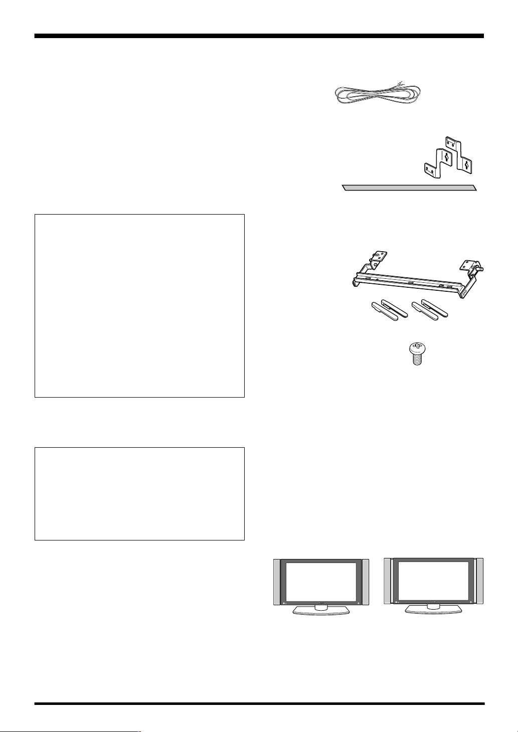
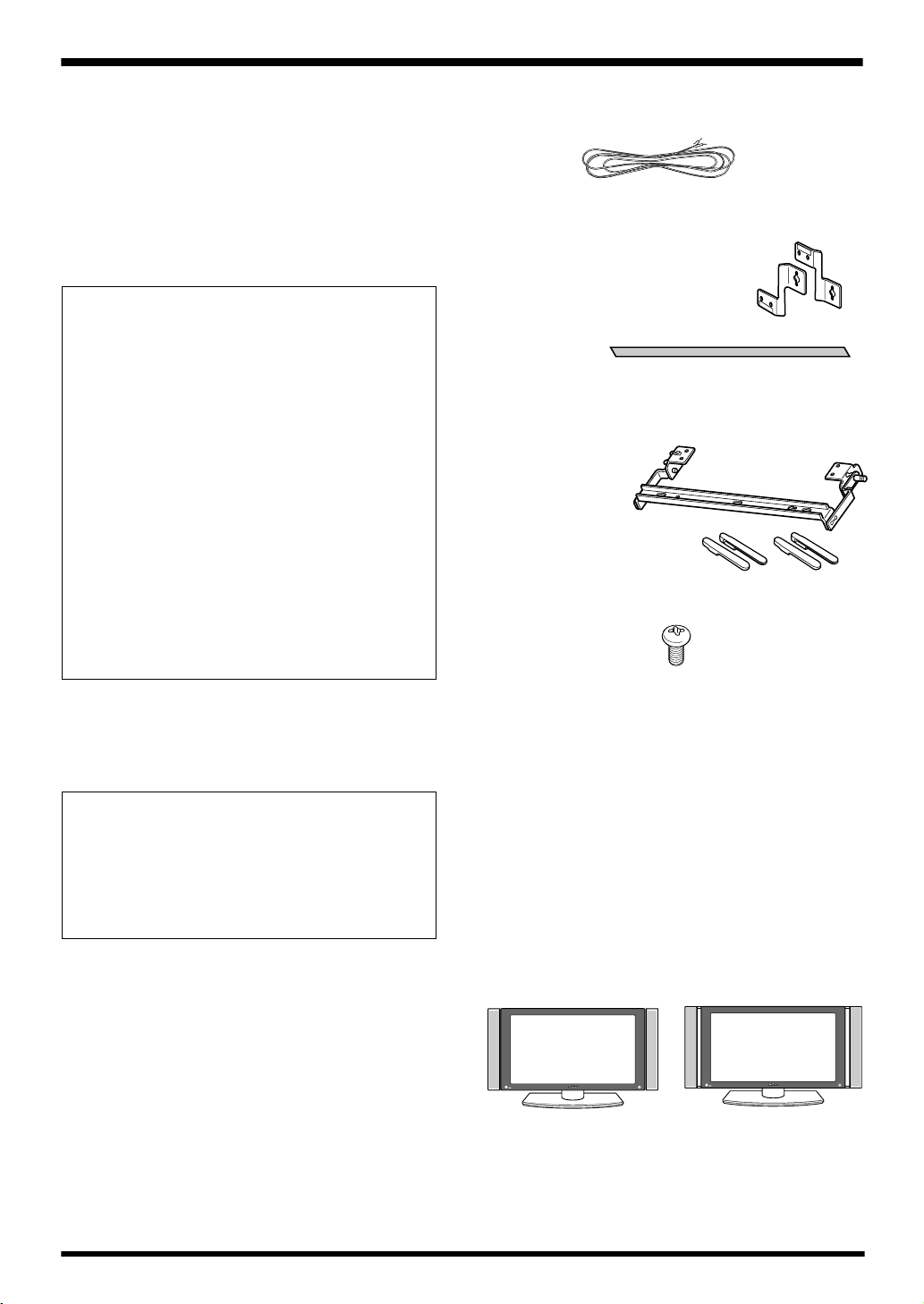
CHECKING THE ACCESSORIES
7 Speaker cable x 2
7 Speaker mounting fittings (Used when installing the
speakers flush with the display)
Bracket for flush mounting (RIGHT) x 2
Bracket for flush mounting (LEFT) x 2
Padding strip x 2
7 Speaker mounting fittings (used when mounting
the speaker so as to allow angle adjustment)
Bracket for air
mounting (R) x 1
Bracket for air
mounting (L) x 1
Covers (upper) x 2
Covers (lower) x 2
7 Speakers mounting screws
x 12
7 Operating Instructions
NOTE:
÷
Always use the accessory mounting fittings for
installation.
÷
When screws other than those enclosed as accessories
are used to install the speakers, the speakers may drop
off or accidents may be caused. Always use the screws
enclosed as accessories.
Speakers are designed to allow the two methods of
installation shown, in accordance with the user’s preference:
1. Flush: Speakers are mounted flat against the sides of
the display, and fixed in position (non-adjustable).
2. Air: Speakers are mounted apart from the sides of the
display, so as to allow adjustment of their angles.
Flush Air
See the description below for details of the installation.
NOTE:
÷
If you install the speakers flush/air, you cannot use the
buttons on the right side of the display. Please use the
remote control.
2
Page 3
English
CAUTION:
÷
Attach the plasma display to the stand before installing
the speakers. See the Operating Instructions packed together with the stand for how to assemble the stand.
÷
Do not place force on the speakers’ front panel grille net,
or stick your finger or other object into the front of the
speaker, since you may damage the grille net or speaker
unit itself.
÷
When using the “Air” method of
mounting speakers: if the speaker angle
is changed, be sure to lock the speaker
before use, to prevent it from moving.
If the speaker is left in the movable
position, personal injury could results by
pinching fingers in the gap between
speaker and display.
INSTALLATION ON THE PLASMA
DISPLAY
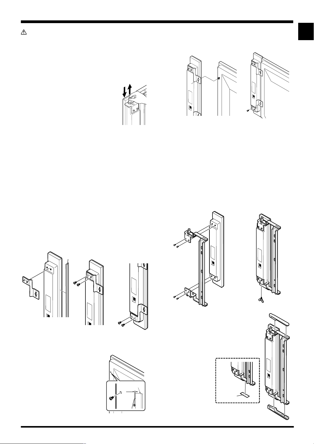
Flush mount (for fixed-angle installation)
Perform installation according to the following steps 1 to 2.
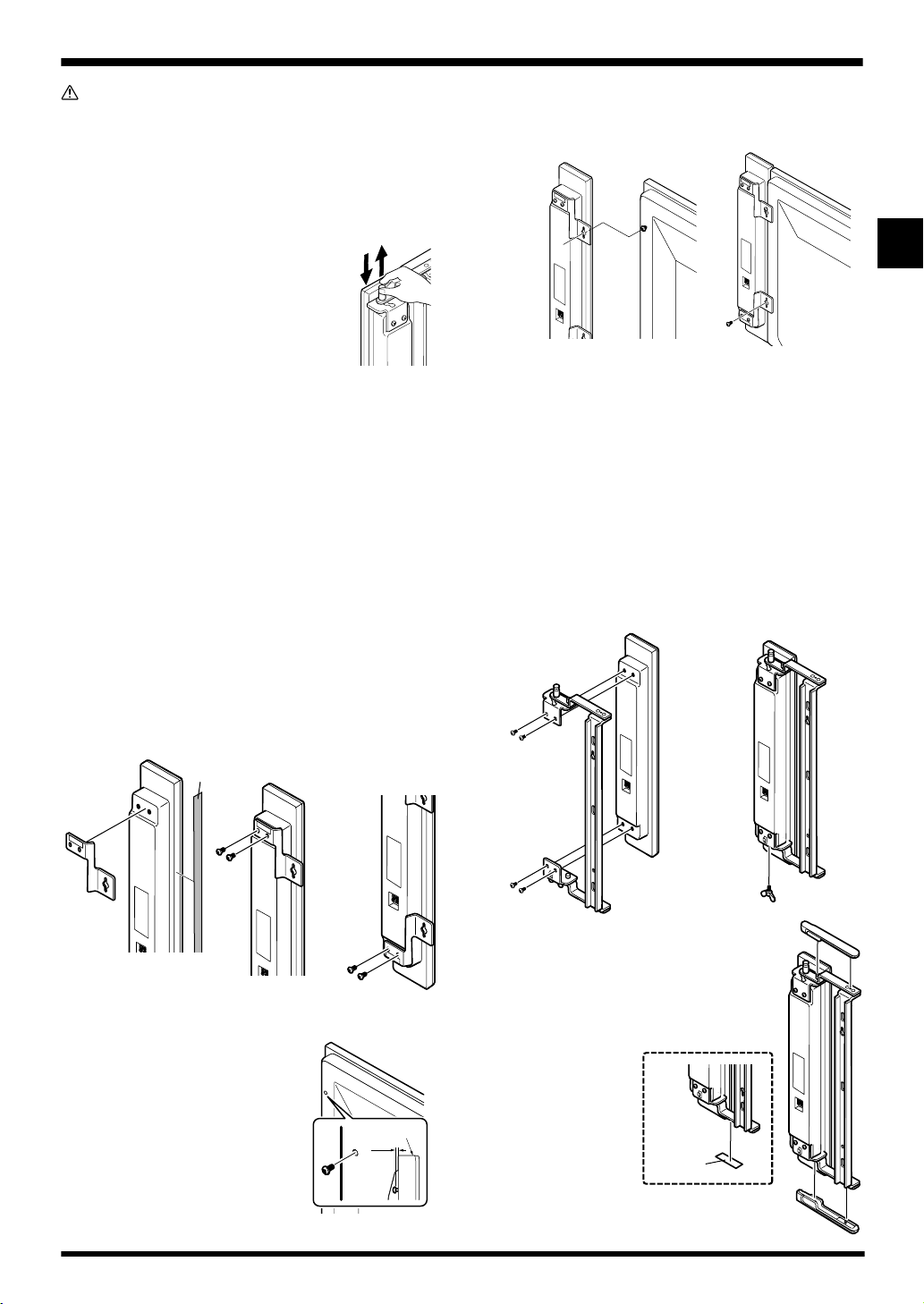
1 Attach the mounting fittings to the
speakers.
The illustration below shows the right speaker. Attach the left
side mounting fitting in the same way.
1 Attach a bracket (RIGHT) to the top of the right speaker,
as shown.
2 Attach another bracket (RIGHT) to the bottom of the
speaker in the same way.
Padding
strip
1
* Apply the padding strip to
the side of the speaker.
2
2 Hang the speaker on the upper screw.
3 Fix the lower screw temporarily.
4 Adjust the position of the speaker and then fix the upper
and lower screws firmly.
2
4
3
INSTALLATION ON THE PLASMA
DISPLAY
Air mount (for adjustable-angle installation)
Perform installation according to the following steps 1 to 2.
1 Attach the mounting fittings to the
speakers.
The illustration below shows the right speaker. Attach the left
side mounting fitting in the same way.
1 Attach the speaker bracket (R) to the right-side speaker.
Remove the locking screw as shown.
English
2 Attach the speakers to the display.
The illustration below shows how to attach of the right speaker.
Attach the left speaker in the same way.
1 Fix the upper screw temporarily in
advance to hang the speaker on the
display (In this case, leave a space
of about 5 mm between the head
of the screw and the display).
The display
5 mm
Locking screw
The locking screw is located in the
bottom side of the speaker only.
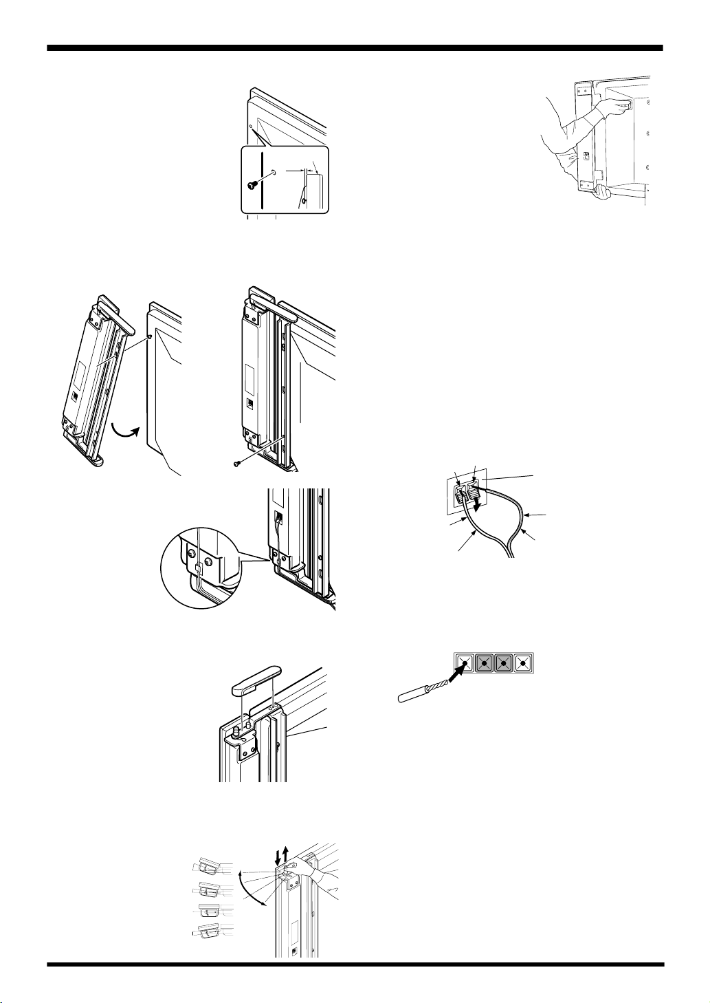
2 Attach the top and bottom covers.
The right and left lower speaker
brackets are pre-applied with twosided tape to prevent the lower covers
from dropping.
Remove the
protective paper
from the tape
before fixing the
covers in place.
Protective
paper
3
Page 4
English
ª··ª
RL
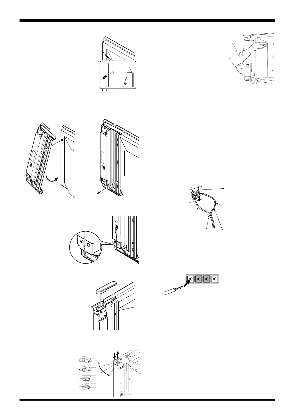
2 Attach the speakers to the display.
The illustration below shows how to attach
of the right speaker. Attach the left speaker
in the same way.
1 Fix the upper screw temporarily in
advance to hang the speaker on the
display (In this case, leave a space
of about 5 mm between the head
of the screw and the display).
2 Hang the speaker on the upper screw.
3 Fix the lower screw temporarily.
4 Adjust the position of the speaker and then fix the upper
and lower screws firmly.
2
4
3
The display
5 mm
NOTE:
÷
When the display is to be
moved after speaker installation, do not hold the display by
the speakers. Hold the display
with one hand on the bottom
of the unit and the other on the
handle on the rear. Do not hold
the speakers and raise the
display. This may cause the
deformation or damage of
products.
CONNECTION TO A PLASMA
DISPLAY
1 Connecting the speaker cables
1 Switch off the power of the plasma display.
2 Connect the input terminals of the speaker system and
the speaker output terminals of the plasma display with
the accessory speaker cable. Make sure the positive (ª)
and negative (·) terminals match when connecting.
1. Push the lever, insert the cable into the hole, and release
the lever.
· terminal (black)
ª terminal (red)
Input terminal of speaker
5 Secure the cable with the cable clip as shown, then press
the remaining speaker cable into the groove (in the lower
cover).
ì Changing the Speaker Angle
1 Remove the upper cover.
2 After pulling up the locking lever, change
the speaker angle as desired, then push
the locking lever down again.
The speakers can be
adjusted in one of
four angle positions
as desired.
20°
10°
0°
10°
10°
10°
10°
White with gray line
White
To the· terminal
(Speaker input terminals of the speaker system)
2. For the output terminals on the plasma display, push the
lever, insert the cable into the hole, and release the lever.
÷ After connection to the terminals, pull lightly on the cable
to confirm that the tips of the cable are properly connected to the terminals. An imperfect connection can
cause sound interruptions and noise.
÷ When cable cores stick out and ª and · lines are short-
circuited, an excessive load will be applied to the plasma
display and the operation will stop or trouble will be
caused.
÷ When the polarity is reversed for one speaker (left or right)
at the time of connection to the plasma display, the bass
reproduction will be reduced, the sound positioning will
be lost, and a correct stereo effect will not be obtained.
To the ª terminal
Output terminal of plasma
display
4
Page 5
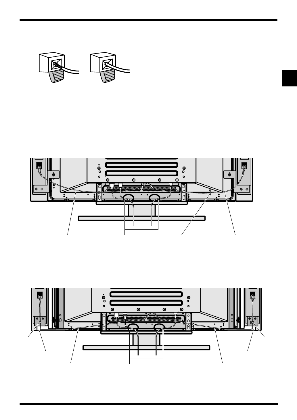
÷ If you insert the speaker cord too far so that the insulation
is touching the speaker terminal, you may not get any
sound.
< right > < wrong >
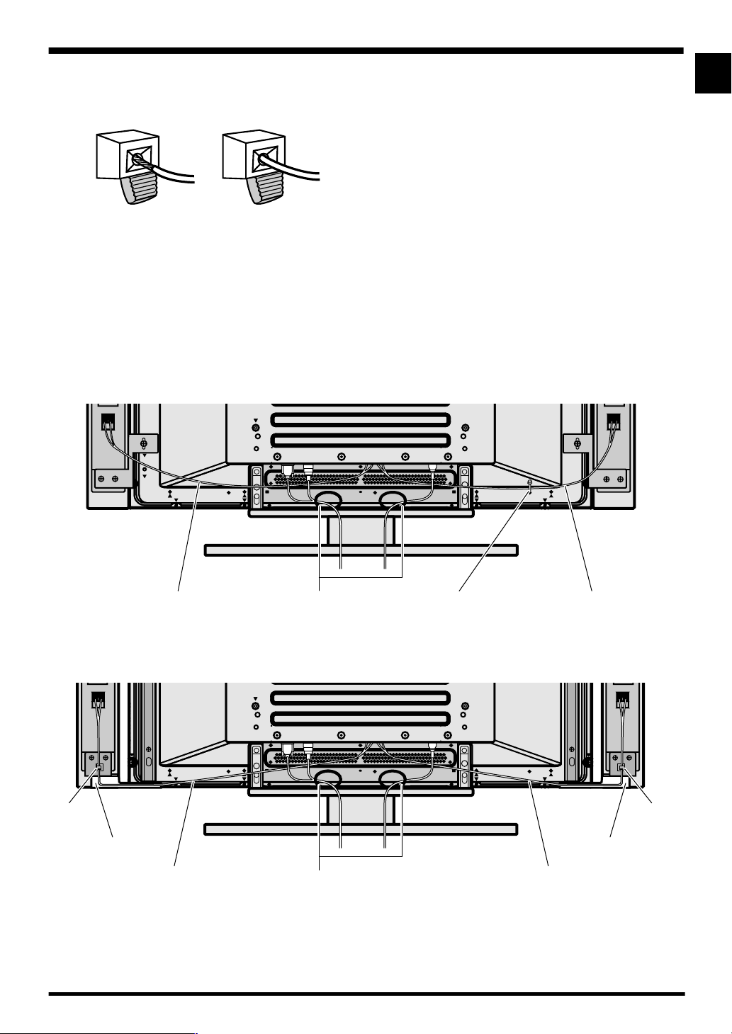
2 How to route cables
Speed clamps are included with the plasma display for
tidying your cables and keeping extra cable length out of the
way.
Flush mount (for fixed-angle installation)
English
English
Speed clampsSpeaker cable Speaker cableWiring clamp
Air mount (for adjustable-angle installation)
Cable clip Cable clip
Cover
Speaker cable Speaker cable
Wiring clamp
Use the supplied wiring clamp to hide the cables from view.
Cover
5
Page 6
English
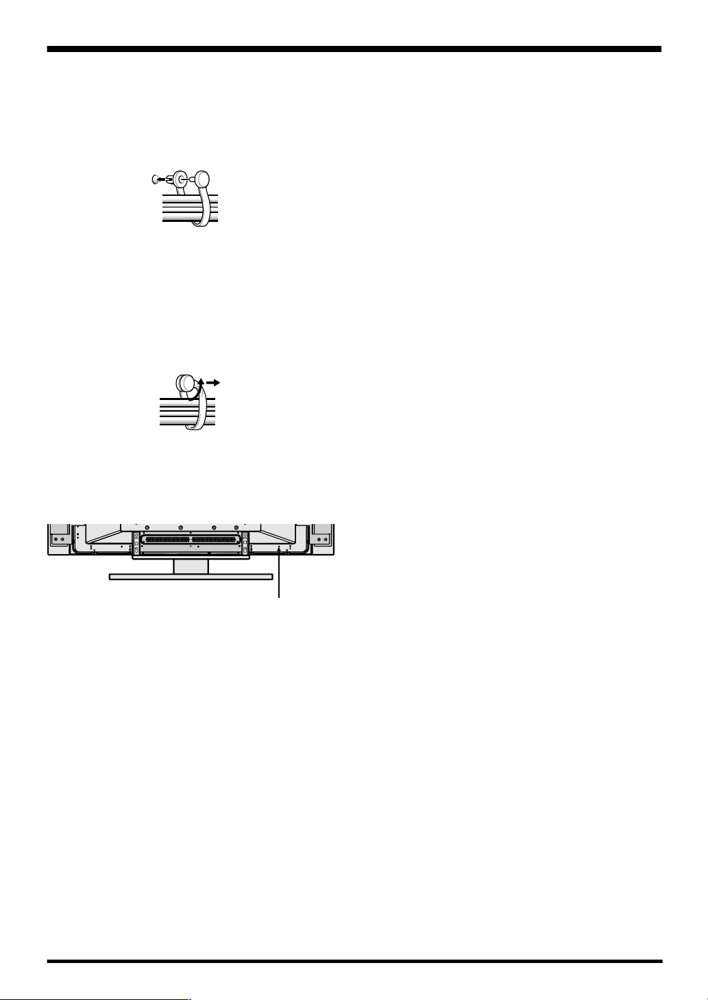
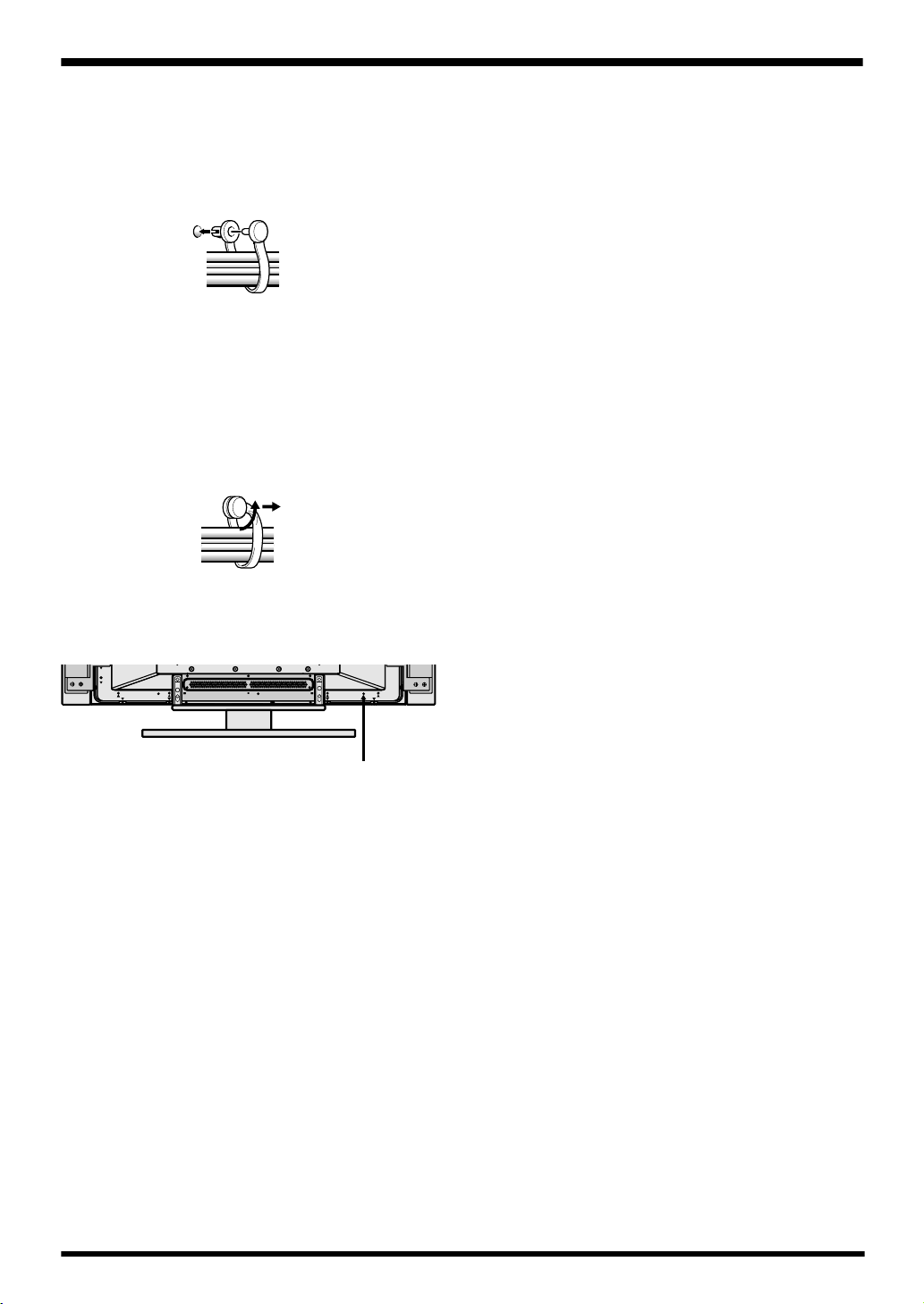
• Organize cables together using the
speed clamps provided with the
plasma display.
Insert 1 into an appropriate hole on the rear of the unit, then
snap 2 into the back of 1 to fix the clamp.
1
Speed clamps are designed to be difficult to undo once in
place. Please attach carefully.
To remove speed clamps
Using pliers, twist the clamp 90° and pull it outward.
In some cases the clamp may have deteriorated over time
and may be damaged when removed.
To attach the speed clamps to the main unit
Connect the speed clamps using the 1 hole marked with •
below, depending on the situation.
2
CABINET MAINTENANCE
÷ Use a polishing cloth or dry cloth to wipe off dust and
dirt.
÷ When the cabinet is very dirty, wipe with a soft cloth
moistened with water-diluted cleanser; then wipe again
with a dry cloth. Do not use furniture wax or cleaners.
They may damage the surface of the cabinet.
÷ Never use thinner, benzine, insecticide sprays and other
chemicals on or near the cabinets, since these will corrode the surfaces.
÷ When a chemical cloth is used, read the cautions for the
chemical cloth carefully.
SPECIFICATIONS
Cabinet : Bass-reflex type
Used speakers (two-way system) :
Woofer (for low tones) ............................ Oval cone type
Tweeter (for high tones)....................... 2 cm dome type
Nominal impedance ..................................................... 8 Ω
Frequency Range..................................... 60 to 20,000 Hz
Sensitivity ................................ 82 dB/W (at 1 m distance)
Permissible input :
Max. input ............................................................... 13 W
Rated input .............................................................. 4 W
Crossover frequency ................................................ 2 kHz
External Dimensions
PDP-S25-LR (for 50 in. (127 cm))
........................................ 95 (W) x 737 (H) x 62 (D) mm
PDP-S26-LR (for 43 in. (110 cm))
........................................ 95 (W) x 652 (H) x 62 (D) mm
Weight
PDP-S25-LR (for 50 in. (127 cm)) .......................... 1.7 kg
PDP-S26-LR (for 43 in. (110 cm)) .......................... 1.6 kg
Accessory parts (for 2 speakers)
.............................................................. Speaker cable x 2
........................................................ Screw (M5 x 10) x 12
............................................... Bracket for flush mounting
Right (RIGHT) x 2
Left (LEFT) x 2
................................................... Bracket for air mounting
Right x 1
Left x 1
................................................................ Padding strip x 2
................................................................................ Covers
Upper x 2
Lower x 2
................................................ Operating Instructions x 1
NOTE:
Specifications and design subject to possible modification
without notice, due to improvements.
Published by Pioneer Corporation.
Copyright © 2004 Pioneer Corporation.
All rights reserved.
6
Page 7
English
English
7
Page 8
Français
Merci pour votre achat de cet appareil Pioneer.
Veuillez lire attentivement toutes ces instructions de
fonctionnement avant d’utiliser votre enceinte acoustique
de façon à pouvoir en tirer le meilleur profit. Après lecture
complète du livret d’instructions de fonctionnement, le
ranger dans un endroit sûr afin de pouvoir vous y reporter
facilement en cas de besoin lors de l’utilisation de l’enceinte
acoustique.
AVANT USAGE
÷ L’impédance nominale de cette enceinte acoustique est
de 8 Ω.
÷ Afin d’éviter d’endommager l’enceinte acoustique,
suite à une surcharge à l’entrée, veuillez observer
les précautions suivantes:
÷ Ne pas fournir aux haut-parleurs une alimentation
supérieure à la valeur maximale admise, sinon
l’appareil risque d’être endommagé ou un incendie
pourrait éclater.
÷ En connectant ou en déconnectant les fiches à
plots, s’assurer que l’alimentation de l’amplificateur
est coupée.
÷ En utilisant un é galisateur graphique pour
accentuer les sons forts dans la plage des hautes
fréquences, ne pas régler l’amplificateur à un
volume excessif.
÷ Ne pas contraindre un amplificateur de faible
puissance à fonctionner à un volume sonore
poussé (la distorsion harmonique de l’amplificateur
sera accrue, ce qui risquerait d’endommager le
haut-parleur).
÷ Manipuler les haut-parleurs avec suffisamment de
soin, car autrement, l’enjoliveur frontal et le coffret
risqueraient d’être endommagés ou hors d’usage en
les soumettant à des chocs externes exagérés.
VÉRIFICATION DES ACCESSOIRES
7 Câbles de haut-parleur x 2
7 Attaches de montage de haut-parleur (Utilisées pour
installation des haut-parleurs à ras de l’écran)
Support pour montage à ras
(droit “RIGHT”) x 2
Support pour montage à ras
(gauche “LEFT”) x 2
Tige de rembourrage x 2
7 Attaches de fixation de haut-parleur (Utilisées pour
installation des haut-parleurs à réglage d’angle)
Support pour montage
pivotant (droit) x 1
Support pour
montage pivotant
(gauche) x 1
Couvercles (supérieurs) x 2
Couvercles (inférieurs) x 2
7 Vis pour montage des haut-parleurs
x 12
÷ Si un écran d’ordinateur à écran cathodique (CRT) ou un
moniteur à écran cathodique (CRT) est placé à proximité
des haut-parleurs, il risque de présenter des interférences
ou une dénaturation des couleurs. Dans ce cas, éloignez
le moniteur des haut-parleurs.
Remarques sur l’installation:
Ce produit est vendu en assumant qu’il sera installé par
un personnel suffisamment expérimenté et qualifié. Faites
toujours réaliser le montage et l’installation par un
spécialiste ou par votre revendeur.
PIONEER ne peut être tenu responsable pour tout
dommage causé par une erreur d’installation ou de
montage, une mauvaise utilisation ou un désastre naturel.
7 Mode d’emploi
REMARQUE:
÷
Utilisez toujours les accessoires de montage fournis pour
l’installation.
÷
Si des vis autres que celles ci-jointes sont utilisées pour
installer les haut-parleurs, ceux-ci peuvent se détacher
et tomber, ou des accidents risquent de se produire.
Utilisez toujours les vis fournies comme accessoires.
Les haut-parleurs sont conçus en vue des deux méthodes
d’installation illustrées, en fonction des préférences de
l’utilisateur.
1. A ras: Les haut-parleurs sont montés à ras contre les
flancs de l’écran et immobilisés (non ajustables).
2. Pivotant: Les haut-parleurs sont montés à l’écart des
flancs de l’écran, ce qui permet d’ajuster leur angle.
Montage à ras Montage pivotant
Se référer à la description ci-dessous pour les détails de
l’installation.
REMARQUE:
÷
Si vous installez les haut-parleurs en montage à ras/
pivotant, vous ne pourrez pas utiliser les boutons sur
le côté droit de l'écran. Utilisez alors la télécommande.
8
Page 9
Français
ATTENTION:
÷
Avant de procéder à l’installation des haut-parleurs, fixez
l’écran plasma sur son socle. Se référer au mode d’emploi
fourni avec le socle pour la procédure d’assemblage.
÷
N’appuyez pas sur la grille souple du panneau avant du
haut-parleur et n’enfoncez pas le doigt ou un objet dans
l’avant du haut-parleur, car ceci pourrait endommager la
grille souple, voire le haut-parleur proprement dit.
÷
A l’emploi de la méthode de montage
pivotant : Si vous changez l’angle du
haut-parleur, prenez soin de
l’immobiliser avant de l’utiliser pour
éviter son mouvement. Si le hautparleur est laissé en position mobile,
vous risquez de vous blesser en vous
pinçant les doigts dans l’espace entre
le haut-parleur et l’écran.
INSTALLATION SUR L’ÉCRAN
PLASMA
Montage à ras (installation à angle fixe)
Effectuez l’installation avant de passer aux étapes 1 et 2 ci-
après.
1 Fixez les attaches de montage sur les
haut-parleurs.
L’illustration ci-dessous présente le haut-parleur droit. Fixez
l’attache de montage du côté gauche de la même façon.
1 Fixez un support (RIGHT) sur le haut du haut-parleur,
comme illustré.
2 Fixez l’autre support (RIGHT) sur le bas du haut-parleur
de la même façon.
Tige de
rembourrage
1
*Placez la tige de
rembourrage sur le
côté du haut-parleur.
2
2 Suspendez le haut-parleur sur la vis supérieure.
3 Fixez temporairement la vis inférieure.
4 Ajustez la position du haut-parleur, puis serrez fermement
les vis supérieures et inférieures.
2
4
3
INSTALLATION SUR L’ÉCRAN
PLASMA
Montage pivotant (installation à angle réglable)
Effectuez l’installation avant de passer aux étapes 1 et 2 ci-
après.
1 Fixez les attaches de montage sur les
haut-parleurs.
L’illustration ci-dessous présente le haut-parleur droit. Fixez
l’attache de montage du côté gauche de la même façon.
1 Fixez le support de montage (droit) sur le haut-parleur
droit. Déposez la vis de blocage comme illustré.
Français
2 Fixez les haut-parleurs sur l’écran.
L’illustration suivante indique comment
fixer le haut-parleur droit. Procédez de la
même manière pour celui de gauche.
1 Fixez temporairement à l’avance la
vis suppérieure pour suspendre le
haut-parleur sur l’écran. (A ce stade,
laissez un espace d’environ 5 mm
entre la tête de la vis et l’écran.)
L’écran
5 mm
Vis de blocage
La vis de blocage se trouve
uniquement sur le fond du hautparleur.
2 Fixez les couvercles supérieur et inférieur.
Les supports inférieurs gauche et droit
sont munis à l’avance d’une bande à
deux faces pour
empêcher la chute
des couvercles
inférieurs. Enlevez le
papier protecteur de
la bande avant de
fixer les couvercles.
Papier
protecteur
9
Page 10
Français
ª··ª
RL
2 Fixez les haut-parleurs sur l’écran.
L’illustration suivante indique comment
fixer le haut-parleur droit. Procédez de la
même façon pour celui de gauche.
1 Fixez temporairement à l’avance la
vis supérieure pour suspendre le
haut-parleur sur l’écran. (A ce stade,
laissez un espace d’environ 5 mm
entre la tête de la vis et l’écran.)
2 Suspendez le haut-parleur sur la vis supérieure.
3 Fixez temporairement la vis inférieure.
4 Ajustez la position du haut-parleur, puis serrez fermement
les vis supérieures et inférieures.
2
5 Immobilisez le câble avec le
collier, puis enfoncez le reste du
câble de haut-parleur
dans la rainure
(dans le couvercle
inférieur).
4
3
L’écran
5 mm
REMARQUE:
÷
Si l’écran doit être déplacé
après l’installation des hautparleurs, ne le tenez pas par
les enceintes. Tenez l’écran
d’une main par le bas, et de
l’ autre avec la poignée à
l’arrière. Ne pas soulever
l’écran en le tenant par les
haut-parleurs. Il pourrait
s’ensuivre une déformation
ou des dégâts aux produits.
BRANCHEMENT A L’ECRAN
PLASMA
1 Branchez les câbles de haut-parleur.
1 Coupez l’alimentation de l’écran plasma.
2 Raccordez les bornes d’entrée du système de haut-
parleurs et les bornes de sortie de l’écran plasma avec
un câble de haut-parleur accessoire. Assurez vous
qu’en étant connectées, les bornes positives ª et
négatives · correspondent.
1. Appuyez sur le levier, insérez le câble dans le trou, puis
relâchez le levier.
Borne · (noir)
Blanc
Vers la borne ·
Borne ª (rouge)
Borne d’entrée du hautparleur.
Blanc à ligne grise
Vers la borne ª
(Bornes d’entrée des haut-parleurs)
ì Changement de l’angle du haut-parleur
1 Déposez le couvercle supérieur.
2 Après avoir relevé le levier de blocage,
modifiez l’angle du haut-parleur selon
vos préf érences, puis enfoncez à
nouveau le levier de blocage.
Les haut-parleurs
peuvent s’ajuster à
une des quatre
positions prévues.
10
20°
10°
0°
10°
10°
10°
10°
2. Pour les bornes d’entrée de l’écran plasma, appuyez sur
le levier, insérez le câble dans le trou, puis relâcher le levier.
Bornes d’entrée de
l’écran plasma
÷ Après l’avoir connecté aux bornes, tirez légèrement le
câble vers vous, afin de vous assurer que les extrémités
sont correctement branchées aux bornes. Un
branchement incorrect peut être à l’origine de coupures
de son ou de bruits.
÷ Si des brins du noyau de câble dépassent et les lignes ª
et · sont court-circuitées, l’écran plasma sera exposé à
une charge excessive et l’opération s’arrêtera ou sera
dérangée.
÷ Si la polarité est inversée sur un haut-parleur (celui de
gauche ou de droite), au moment de la connexion à l’écran
plasma, la reproduction des basses sera altérée,
l’orientation sonore sera disparaîtra et un effet stéréo
correct ne sera pas obtenu.
Page 11
÷ Si vous insérez le cordon de haut-parleur trop loin au point
que l’isolant touche la borne de huat-parleur, il est possible qu’aucun son ne soit obtenu.
< correct > < incorrect >
Français
2 Comment cheminer les câbles
Des serre-câbles sont fournis avec l’écran plasma pour
mettre de l’ordre dans vos câbles et tenir la longueur de
câble supplémentaire non-utilisé à l’écart.
Montage à ras (installation à angle fixe)
Montage pivotant (installation à angle réglable)
Français
Serre-câble rapideCâble de haut-parleur Câble de haut-parleurCollier
Collier de
câble
Couvercle
Câble de haut-parleur Câble de haut-parleur
Collier
Utilisez les colliers fournis pour cacher les câbles.
Collier de
câble
Couvercle
11
Page 12
Français
• Regroupez les câbles à l’aide des serre-
câbles rapides fournis avec l’écran
plasma.
Introduisez 1 dans le perçage adéquat à l’arrière de l’appareil,
puis fermez le serre-câble en insérant 2 à l’arrière de 1, le
faisant cliquer.
Les serre-câbles sont conçus pour être difficiles à défaire,
une fois fermés. Nous vous prions de les attacher
prudemment.
Pour enlever les serre-câbles.
À l’aide d’une paire de pinces, tordez le serre-câble à 90° et
tirez-le vers l’extérieur. Dans certains cas le serre-câble a pu
se détériorer avec le temps et peut s’endommager lors de
son retrait.
Fixez les serre-câbles rapides à l’appareil principal.
Connectez les serre-câbles en les insérant dans le trou
désigné par •, comme indiqué ci-dessous, selon la situation.
1
2
ENTRETIEN DU COFFRET
÷ Utiliser un chiffon à polir ou un chiffon sec pour essuyer
la poussière et éliminer les salissures.
÷ Si le coffret est très sale, le frotter avec un chiffon doux
imbibé de liquide à nettoyer dilué d’eau. Ensuite, essuyer
à nouveau avec un chiffon sec. Ne pas utiliser de cire à
meuble ou de produits de nettoyage corrosifs. Ils
risqueraient d’endommager la surface du coffret.
÷ Ne jamais utiliser non plus de diluant, de benzine,
d’insecticides en vaporisateur et autres produits
chimiques sur le coffret ou à proximité, car ils risquent
de corroder les surfaces.
÷ Si l’on utilise un chiffon chimique, lire et observer
attentivement les précautions à prendre pour son usage
adéquat.
SPECIFICATIONS
Coffret : Type bass-reflex
Haut-parleurs utilisés (système à double voie) :
Haut-parleur de graves....................... Type à cône ovale
Haut-parleur d’aigus .....................Type à dôme de 2 cm
Impédance nominale ................................................... 8 Ω
Plage de fréquences................................. 60 à 20.000 Hz
Sensibilité ........................... 82 dB/W (à 1 m de distance)
Entrée admissible :
Entrée max. ............................................................ 13 W
Entrée nominale ...................................................... 4 W
Fréquence de recouvrement ................................... 2 kHz
Encombrement :
PDP-S25-LR (pour 50 pouces (127 cm))
.......................................... 95 (L) x 737 (H) x 62 (P) mm
PDP-S26-LR (pour 43 pouces (110 cm))
.......................................... 95 (L) x 652 (H) x 62 (P) mm
Poids :
PDP-S25-LR (pour 50 pouces (127 cm)) ............... 1,7 kg
PDP-S26-LR (pour 43 pouces (110 cm)) ............... 1,6 kg
Pièces accessoires (pour 2 haut-parleurs)
..................................................... Câbles de haut-parleur x 2
.............................................................. Vis (M5 x 10) x 12
............................................. Support pour montage à ras
Droit (RIGHT) x 2
Gauche (LEFT) x 2
....................................... Support pour montage pivotant
Droit x 1
Gauche x 1
................................................... Tige de rembourrage x 2
......................................................................... Couvercles
Supérieurs x 2
Inférieurs x 2
............................................................... Mode d'emploi x 1
12
REMARQUE:
Les spécifications et la finition sont susceptibles d’être
modifiées sans préavis en vue de l’amélioration.
Publication de Pioneer Corporation.
© 2004 Pioneer Corporation.
Tous droits de reproduction et de traduction réservés.
Page 13

Deutsch
Wir danken Ihnen dafür, dass Sie sich für ein Produkt von
Pioneer entschieden haben.
Bitte lesen Sie vor der Verwendung Ihrer Lautsprecheranlage
diese Anleitung aufmerksam durch, um die Vorzüge des
Systems optimal ausnützen zu können. Nachdem Sie die
Bedienungsanleitung durchgelesen haben, bewahren Sie
sie sorgfältig auf, um sich im Bedarfsfall jederzeit darauf
beziehen zu können./
VOR DER VERWENDUNG
÷ Die Nennimpedanz dieses Lautsprechersystems beträgt 8
Ohm.
÷ Um eine Beschädigung des Lautsprechersystems durch
ein zu starkes Eingangssignal zu vermeiden, müssen
die folgenden Hinweise unbedingt beachtet werden:
÷ Keinesfalls die max. zulässige Belastbarkeit
(Eingangspegel) der Lautsprecher überschreiten.
Anderenfalls können Schäden oder Brandgefahr
resultieren.
÷ Vor dem Anschließen und Abziehen von Stiftsteckern
muss die Stromversorgung zum Verstärker unbedingt
auf OFF gestellt werden.
÷ Wenn ein Graphik-Equalizer verwendet wird, um die
Töne im Hochfrequenzbereich zu verstärken, darf die
Lautstärke des Verstärkers nicht zu hoch eingestellt
werden.
÷ Versuchen Sie nicht, hohe Lautstärken über einen
Lautsprecher mit nicht ausreichender Kapazität
wiederzugeben (dies führt zu einer Verstärkung des
Klirrfaktors; außerdem kann eine Beschädigung der
Lautsprecher die Folge sein).
÷ Die Lautsprecher sind vorsichtig zu behandeln, da
Ziergitter und Gehäuse durch starke Stöße und
Erschütterungen verkratzt bzw. beschädigt werden
können.
÷ Bei unzureichender Entfernung von CRT-Computer-
Monitoren oder CRT-Monitoren können die
Lautsprecher Bildrauschen oder Farbstörungen
verursachen. In diesem Fall die Entfernung zwischen
Lautsprecher und Display vergrößern.
Hinweise zur Installation
Dieses Produkt wird unter der stillschweigenden Voraussetzung vertrieben, dass es von ausreichend qualifiziertem Personal installiert wird. Lassen Sie es daher vom Fachmann bzw.
Ihrem Händler aufstellen bzw. montieren und einrichten.
PIONEER lehnt jegliche Haftung für Schäden ab, die durch Fehler bei der Installation bzw. Montage oder durch Bedienfehler,
Veränderungen oder höhere Gewalt entstehen.
ÜBERPRÜFEN DER ZUBEHÖRTEILE
7 Lautsprecherkabel x 2
7 Lautsprecher-Montagehalterungen (für eine bündig
mit dem Display abschließende Befestigung der
Lautsprecher)
Halterung für bündige Befestigung
(rechts “RIGHT”) x 2
Halterung für bündige Befestigung
(links “LEFT”) x 2
Polsterleiste x 2
7 Lautsprecher-Montagehalterungen (für eine
Befestigung, die eine Justierung des Winkels der
Lautsprecher gestattet)
Halterung für versetzte
Befestigung (rechts) x 1
Halterung für versetzte
Befestigung (links) x 1
Abdeckung (obere) x 2
Abdeckung (untere) x 2
7 Befestigungsschrauben für die Lautsprecher
x 12
7 Bedienungsanleitung
HINWEISE:
÷
Zur Installation der Lautsprecher stets die als Zubehör
mitgelieferten Befestigungsteile verwenden.
÷
Wenn andere als die mitgelieferten Schrauben zur
Montage der Lautsprecher verwendet werden, können
die Lautsprecher herunterfallen, oder es können Unfälle
passieren. Daher stets nur die als Einbausatz
mitgelieferten Schrauben verwenden.
Diese Lautsprecher sind so ausgelegt, dass sie auf zwei
verschiedene Weisen am Display befestigt werden können:
1. Bündig: Die Lautsprecher werden so an den Seiten des
Displays befestigt, dass sie bündig mit den Seitenwänden
abschließen und in dieser Position fixiert sind (ihr Winkel
kann nicht justiert werden).
2. Versetzt: Die Lautsprecher werden in einem gewissen
Abstand von den Seiten des Displays befestigt, um eine
Justierung ihres Winkels zu gestatten.
bündig
versetzt
Deutsch
Beziehen Sie sich hinsichtlich weiterer Einzelheiten der
Installation auf die entsprechenden Erläuterungen.
HINWEIS:
÷
Bei bündiger/ versetzter Montage der Lautsprecher
können die Funktionstasten an der rechten Seite des
Displays nicht betätigt werden. Verwenden Sie in einem
solchen Fall die Fernbedienung.
13
Page 14

Deutsch
VORSICHT:
÷
Montieren Sie das Plasma-Display vor Installation der
Lautsprecher auf dem Ständer. Beziehen Sie sich
hinsichtlich der Montage des Ständers auf die
mitgelieferte Gebrauchsanleitung.
÷
Üben Sie keinen Druck auf die Frontverkleidung der
Lautsprecher aus, und stecken Sie weder Finger noch
andere spitze Gegenstände in die Frontverkleidung, da dies
eine Beschädigung der Frontverkleidung oder des
Lautsprechers selbst verursachen kann.
÷
Bei versetzter Befestigung der Lautsprecher: Achten Sie
nach einer Veränderung des Winkels darauf,
den Lautsprecher vor dem Gebrauch in der
neuen Position zu arretieren, damit er sich
nicht bewegen kann. Wenn der Lautsprecher nicht in der gewünschten Stellung
arretiert wird, besteht die Gefahr von
Verletzungen, falls Finger in dem Spalt
zwischen Lautsprecher und Display
eingeklemmt werden.
MONTAGE AM PLASMA-DISPLAY
Bündig abschließende Befestigung
(Winkel nicht verstellbar)
Zur Montage der Lautsprecher führen Sie Schritt 1 und 2
unten aus.
1 Befestigen Sie die Montagehalterungen
an den Lautsprechern.
Die nachstehenden Diagramme zeigen die Befestigung der
rechten Montagehalterungen am rechten Lautsprecher.
Befestigen Sie die linken Montagehalterungen auf gleiche
Weise am linken Lautsprecher.
1 Befestigen Sie eine der beiden Montagehalterungen
(RIGHT) wie unten gezeigt an der Oberkante des rechten
Lautsprechers.
2
Befestigen Sie die zweite Montagehalterung (
gleiche Weise an der Unterkante des rechten Lautsprechers.
* Befestigen Sie die
1
Polsterleiste
Polsterleiste an der Seite
des Lautsprechers.
RIGHT
) auf
2
2 Hängen Sie den Lautsprecher in die obere Schraube ein.
3 Bringen Sie die untere Schraube provisorisch an.
4 Bringen Sie den Lautsprecher in Arbeitsstellung, und ziehen
Sie dann die obere und die untere Schraube fest an.
2
4
3
MONTAGE AM PLASMA-DISPLAY
Versetzte Befestigung (für Winkelverstellung)
Zur Montage der Lautsprecher führen Sie Schritt 1 und 2
unten aus.
1 Befestigen Sie die Montagehalterungen
an den Lautsprechern.
Die nachstehenden Diagramme zeigen die Befestigung der
rechten Montagehalterung am rechten Lautsprecher.
Befestigen Sie die linke Montagehalterung auf gleiche Weise
am linken Lautsprecher.
1 Befestigen Sie die rechte Montagehalterung am rechten
Lautsprecher.
Entfernen Sie die Sicherungsschraube wie unten gezeigt.
Sicherungsschraube
2 Montieren Sie die Lautsprecher an das
Display.
Das nachstehende Diagramm zeigt die
Montage des rechten Lautsprechers.
Montieren Sie den linken Lautsprecher auf
gleiche Weise an das Display.
1
Bringen Sie die obere Schraube im
Voraus provisorisch an, um den
Lautsprecher an das Display zu
hängen (lassen Sie dabei einen
Abstand von ca. 5 mm zwischen dem
Schraubenkopf und der Oberfläche
des Displaygehäuses frei).
14
Display
5 mm
Die Sicherungsschraube befindet sich
jeweils an der Unterseite des Lautsprechers.
2 Bringen Sie die obere und die untere
Abdeckung an.
Die rechte und die linke untere Lautsprecherhalterung sind mit doppelseitig
haftendem Klebeband befestigt, um ein
Herunterfallen der unteren Abdeckungen zu
verhindern. Entfernen Sie die Schutzfolie vom
Klebeband, bevor Sie
die Abdeckung in
Arbeitsstellung befestigen.
Schutzfolie
Page 15

Deutsch
ª··ª
RL
2 Montieren Sie die Lautsprecher an das
Display.
Das nachstehende Diagramm zeigt die
Montage des rechten Lautsprechers.
Montieren Sie den linken Lautsprecher
auf gleiche Weise an das Display.
1
Bringen Sie die obere Schraube im
Voraus provisorisch an, um den
Lautsprecher an das Display zu
hängen (lassen Sie dabei einen
Abstand von ca. 5 mm zwischen dem
Schraubenkopf und der Oberfläche
des Displaygehäuses frei).
2 Hängen Sie den Lautsprecher in die obere Schraube ein.
3 Bringen Sie die untere Schraube provisorisch an.
4 Bringen Sie den Lautsprecher in Arbeitsstellung, und ziehen
Sie dann die obere und die untere Schraube fest an.
2
5
Sichern Sie das Kabel wie in der Abbildung gezeigt mit der
Kabelklemme, und passen Sie den restlichen Abschnitt des
Lautsprecherkabels in die Nut (in der unteren Abdeckung)
ein.
4
3
Display
5 mm
HINWEIS:
÷
Wenn das Display nach Installation der Lautsprecher
umgestellt werden soll, halten Sie diesen nicht an den
Lautsprechern. Fassen Sie
mit der einen Hand unter den
Boden des Displays und
halten diesen mit der anderen
Hand an dem Griff auf der
Rückseite. Das Display nicht
an den Lautsprechern hochheben. Dies könnte zu einer
Verformung oder Beschädigung des Produktes führen.
ANSCHLUSS AN
PLASMA-DISPLAY
1 Anschließen der Lautsprecher-Kabel
1 Das Plasma-Display ausschalten.
2 Die Ein- und Ausgangsklemmen des
Lautsprechersystems über das zum Zubehör
gehörende Lautsprecherkabel mit dem Plasma-Display
verbinden. Auf den richtigen Anschluss von
Plusklemme ª und Minusklemme · achten.
1. Den Hebel nach unten drücken, das Kabel in die Öffnung
einführen und dann den Hebel wieder loslassen.
·-Klemme (schwarz)
weiß
an ·-Klemme
(Eingangsbuchsen des Lautsprechersystems)
ª-Klemme (rot)
Eingangsklemmen des
Lautsprechers
weiß mit grauem
Streifen
an ª-Klemme
Deutsch
ì Verstellen des Lautsprecherwinkels
1 Entfernen Sie die obere Abdeckung.
2 Ziehen Sie den Arretierhebel nach oben, verändern Sie
den Winkel des Lautsprechers wunschgemäß, und
drücken Sie dann den Arretierhebel wieder nach unten.
Die vier rechts gezeigten
Einstellungen des
Lautsprecherwinkels
stehen zur Verfügung.
20°
10°
0°
10°
10°
10°
10°
2. Drücken Sie die Klemmen der Ausgangsbuchsen am
Plasma-Display herunter, stecken Sie die Kabel in die
betreffenden Löcher, und lassen Sie die Klemmen dann
wieder los.
Ausgangsbuchsen des
Plasma-Displays
÷ Nach dem Anschluss an die Klemmen leicht am Kabel
ziehen, um sicherzustellen, dass die Enden des Kabels
richtig an den Klemmen angeschlossen sind. Ein
Wackelkontakt kann Tonaussetzer und Störgeräusche
verursachen.
÷ Wenn Kabeldrähte vorstehen und dadurch ª- und ·-
Leitungen kurzgeschlossen werden, werden am PlasmaDisplay extrem hohe Spannungen verursacht, so dass es
ausfällt oder Störungen bewirkt werden.
÷ Wenn die Polarität für einen Lautsprecher (links oder
rechts) beim Anschluss an das Plasma-Display umgekehrt
ist, wird die Bass-Wiedergabe vermindert, die richtige
Klangeinstellung geht verloren, und ein korrekter StereoEffekt wird nicht erreicht.
15
Page 16

Deutsch
÷ Falls das Lautsprecherkabel zu weit in die
Lautsprecherklemme eingeführt wird, so dass die
Isolierung der Klemme berührt, erfolgt u.U. keine
Wiedergabe über den Lautsprecher.
< richtig > < falsch >
2 Verlegung der Kabel
Das Plasma-Display wird mit Schnellklemmen geliefert, um
die Kabel zu bündeln und zu verhindern, dass zu lange Kabel
stören.
Bündig abschließende Befestigung (Winkel nicht verstellbar)
Versetzte Befestigung (für Winkelverstellung)
Kabelklemme
Abdeckung
Lautsprecherkabel Lautsprecherkabel
Kabelklemme
16
Schnellverschluss-HaltebänderLautsprecherkabel LautsprecherkabelKabelklemme
Kabelklemme
Abdeckung
Verwenden Sie die mitgelieferten
Kabelklemmen, um die Kabel unaufällig
unterzubringen.
Page 17

•
Geordnete Verlegung der Kabel mit Hilfe
der mitgelieferten SchnellverschlussHaltebänder
Den Stift 1 in die dafür vorgesehene Öffnung an der
Rückseite des Geräts stecken und anschließend Teil 2 in
die Rückseite von 1 drücken, um die Halterung zu
befestigen.
1
Die Haltebänder sind so gestaltet, dass sie nach dem Fixieren
nur schwer gelöst werden können. Haltebänder daher
vorsichtig fixieren.
Entfernen der Schnellverschluss-Haltebänder
Verschluss mit einer Zange um 90° drehen und dann nach
außen ziehen. In einigen Fällen kann der Verschluss mit der
Zeit qualitätsgemindert und daraufhin beim Öffnen
beschädigt werden.
Befestigung der Schnellverschluss-Haltebänder
am Hauptgerät
Die Schnellklemmen je nach Situation über das unten mit •
gekennzeichnete Loch 1 anschließen.
2
Deutsch
PFLEGE DES GEHÄUSES
÷ Zum Abwischen von Staub und Verschmutzung kann ein
Poliertuch oder ein trockener Lappen verwendet werden.
÷ Wenn das Gehäuse stark verschmutzt ist, kann es mit
einem weichen, mit verdünntem Haushaltsreiniger
angefeuchteten Lappen gesäubert und dann mit einem
trockenen Lappen abgewischt werden. Keine
Möbelpolitur oder Reinigungsmittel verwenden, da diese
Mittel die Oberfläche des Gehäuses beschädigen können.
÷ Niemals Verdünner, Benzol, Insektensprays oder andere
Chemikalien am oder in der Nähe des Gehäuses
verwenden, da hierdurch die Oberfläche beschädigt wird.
÷ Vor der Verwendung eines chemischen Reinigungstuchs
unbedingt die Vorsichtshinweise sorgfältig durchlesen.
TECHNISCHE DATEN
Gehäuse: Bassreflextyp
Verwendete Lautsprecher (Zweiweg-System):
Woofer (für tiefe Frequenzen)
............................................... Ovaler Konuslautsprecher
Hochtöner (für hohe Frequenzen)
................................................. 2-cm-Kuppellautsprecher
Nennimpedanz ........................................................ 8 Ohm
Frequenzgang ........................................ 60 bis 20,000 Hz
Empfindlichkeit ...................... 82 dB/W (bei 1 m Abstand)
Zulässige Eingangswerte:
Maximaler Eingangswert ....................................... 13 W
Nenn-Eingangswert ................................................. 4 W
Übergangsfrequenz ................................................. 2 kHz
Äußere Abmessungen:
PDP-S25-LR (50 Zoll (127 cm))
.......................................... 95 (B) x 737 (H) x 62 (T) mm
PDP-S26-LR (43 Zoll (110 cm))
.......................................... 95 (B) x 652 (H) x 62 (T) mm
Gewicht:
PDP-S25-LR (50 Zoll (127 cm)) ............................. 1,7 kg
PDP-S26-LR (43 Zoll (110 cm)) ............................. 1,6 kg
Zubehörteile (für 2 Lautsprecher)
....................................................... Lautsprecherkabel x 2
................................................... Schraube (M5 x 10) x 12
.................................. Halterung für bündige Befestigung
(rechts “RIGHT”) x 2
.................................. Halterung für bündige Befestigung
(links “LEFT”) x 2
.............Halterung für versetzte Befestigung (rechts) x 1
............... Halterung für versetzte Befestigung (links) x 1
................................................................. Polsterleiste x 2
...................................................... Abdeckung (obere) x 2
..................................................... Abdeckung (untere) x 2
................................................... Bedienungsanleitung x 1
Deutsch
HINWEIS:
Die technischen Daten und das Design können aus Gründen
der Weiterentwicklung jederzeit ohne vorherige
Ankündigung geändert werden.
Veröffentlicht von Pioneer Corporation.
Urheberrechtlich geschützt © 2004 Pioneer Corporation.
Alle Rechte vorbehalten.
17
Page 18

Italiano
Grazie per avere acquistato questo prodotto Pioneer.
Leggere attentamente queste istruzioni per l’uso prima di
utilizzare il sistema di altoparlanti per avvalersi al massimo
delle sue prestazioni. Conservare poi il manuale in un luogo
sicuro per ogni eventuale futura necessità.
PRIMA DELL’USO
÷ L’impedenza nominale di questo sistema di altoparlanti è
8 ohm.
÷ Per evitare danni al sistema di altoparlanti dovuti a
un sovraccarico d’ingresso, osservare le seguenti
precauzioni:
÷ Fornire al circuito degli altoparlanti un'alimentazione
che non superi il livello massimo d'ingresso
consentito. In caso contrario, sussiste il pericolo di
danni e di un eventuale incendio.
÷ Prima di procedere al collegamento o al distacco
degli spinotti, verificare che l’alimentazione elettrica
dell’amplificatore sia spenta (OFF).
÷ Se si utilizza un equalizzatore grafico per enfatizzare
i suoni alti della gamma di frequenze alte, non
aumentare troppo il volume dell’amplificatore.
÷ Non forzare un amplificatore dotato di bassi a
produrre volumi di suono alti (la distorsione armonica
dell’amplificatore potrebbe aumentare, e gli
altoparlanti potrebbero subire danni).
÷ Si prega di maneggiare con cura gli altoparlanti; la griglia
di schermo e la cassa esterna possono danneggiarsi o
rompersi se sottoposte a colpi esterni molto forti.
÷ Sistemando il video di un computer a tubo catodico (CRT)
o un monitor a tubo catodico (CRT) vicino agli altoparlanti
è possibile che si verifichino delle interferenze o delle
alterazioni di colore. Se ciò si dovesse verificare,
distanziare il monitor dagli altoparlanti.
Note relative all'installazione:
Si presuppone che questo prodotto venga installato da
personale qualificato in possesso della necessaria abilità
e competenza tecnica. Si consiglia di rivolgersi ad uno
specialista del settore o al proprio concessionario per
l'installazione e la regolazione del prodotto.
PIONEER non si assume alcuna responsabilità per
eventuali danni provocati da un'installazione o da un
montaggio eseguiti in modo errato, da un uso improprio,
dalla modificazione dello stesso o da calamità naturali.
VERIFICA DEGLI ACCESSORI IN
DOTAZIONE
7 Cavi per altoparlanti x 2
7 Accessori per il montaggio degli altoparlanti (da
utilizzare in caso di installazione degli altoparlanti in
posizione allineata con lo schermo)
Staffe per il montaggio in posizione
allineata (lato destro “RIGHT”) x 2
Staffe per il montaggio in posizione
allineata (lato sinistro “LEFT”) x 2
Strisce di guarnizione x 2
7 Accessori per il montaggio degli altoparlanti (da utilizzare
in caso di installazione degli altoparlanti in modo da
consentire la regolazione dell’angolo di rotazione)
Staffa per il
montaggio in
posizione libera
(lato destro) x 1
Staffa per il
montaggio in
posizione libera
(lato sinistro) x 1
Coperchietti (superiori) x 2
Coperchietti (inferiori) x 2
7 Viti di montaggio degli altoparlanti
x 12
7 Istruzioni per l’uso
NOTE:
÷
Per l’installazione, utilizzare sempre gli accessori di
montaggio forniti in dotazione.
÷
Se si usano viti diverse da quelle fornite per installare gli
altoparlanti, questi possono cadere o essere causa di
incidenti. Usare sempre le viti fornite in dotazione.
Gli altoparlanti sono stati studiati in modo da consentire i
due metodi di installazione descritti in precedenza, per
adeguarsi alle preferenze dell’utente.
1. Posizione allineata: Gli altoparlanti sono montati in
posizione aderente alle pareti laterali dello schermo, e
fissati in posizione (non regolabili).
2. Posizione libera: Gli altoparlanti sono montati in posizione
libera, staccati dalle pareti laterali dello schermo, onde
consentirne la rotazione per la regolazione dell’angolazione.
Posizione allineata Posizione libera
18
Per istruzioni dettagliate in merito all’installazione, si prega
di vedere la descrizione che segue.
NOTA:
÷
In caso di installazione degli altoparlanti in posizione
allineata e in posizione libera, non è possibile utilizzare i
tasti situati sul lato destro dello schermo. In tal caso fare
uso del telecomando.
Page 19

Italiano
ATTENZIONE:
÷
Prima di installare gli altoparlanti provvedere a fissare lo
schermo al plasma sul proprio supporto. Per istruzioni sul
montaggio dello schermo sul supporto vedere il manuale
di istruzioni fornito con il supporto stesso.
÷
Non esercitare forti pressioni sulla rete a griglia del pannello
anteriore degli altoparlanti, e non inserire le dita o altri oggetti
nel lato anteriore degli altoparlanti. Tali azioni potrebbero
causare danni alla rete a griglia o agli altoparlanti stessi.
÷
Nel caso in cui si proceda all’installazione
degli altoparlanti con il metodo a
“posizione libera”: in caso di modifica
dell’angolazione degli altoparlanti ricordarsi
di fissare bene gli altoparlanti prima di
passare all’uso dell’apparecchio, per evitare
che possano muoversi. Lasciando gli
altoparlanti liberi di muoversi, l’eventuale
inserimento delle dita nello spazio libero
esistente fra gli altoparlanti ed il corpo dell’apparecchio può
provocare lesioni fisiche.
INSTALLAZIONE SUL PANNELLO
AL PLASMA
Montaggio in posizione allineata (installazione ad
angolazione fissa)
L’installazione deve essere eseguita nelle due fasi, 1 e 2,
descritte qui di seguito.
1 Attacco agli altoparlanti degli
accessori per il montaggio
La figura seguente esemplifica la procedura da seguire per
l’altoparlante destro. Eseguire la stessa procedura anche per
l’attacco degli accessori all’altro altoparlante.
1 Applicare una delle due staffe ad uso del lato destro
(RIGHT) sulla parte superiore dell’altoparlante destro,
come indicato.
2 Allo stesso modo, applicare l’altra staffa ad uso del lato
destro (RIGHT) sulla parte inferiore dell’altoparlante destro.
Striscia di
guarnizione
1
*Applicare la striscia di
guarnizione sul lato
dell’altoparlante
2
2 Agganciare l’altoparlante alla vite superiore.
3 Fissare temporaneamente la vite inferiore.
4 Regolare la posizione dell’altoparlante e procedere poi a
stringere saldamente le due viti, superiore ed inferiore.
2
4
3
INSTALLAZIONE SUL PANNELLO
AL PLASMA
Montaggio in posizione libera (installazione ad
angolazione regolabile)
L’installazione deve essere eseguita nelle due fasi, 1 e 2,
descritte qui di seguito.
1 Attacco agli altoparlanti degli
accessori per il montaggio
La figura seguente esemplifica la procedura da seguire per
l’altoparlante destro. Eseguire la stessa procedura anche per
l’attacco degli accessori all’altro altoparlante.
1 Applicare una delle due staffe ad uso del lato destro sul
lato destro dell’altoparlante destro. Togliere la vite di
bloccaggio, come indicato in figura.
Italiano
2 Montaggio degli altoparlanti sul
pannello al plasma
La figura seguente esemplifica la
procedura da seguire per il montaggio
dell’altoparlante destro. Eseguire la stessa
procedura anche per l’altoparlante sinistro.
1 Montare in anticipo, e temporanea-
mente, sul pannello la vite per
l’aggancio dell’altoparlante (lasciando
uno spazio di circa 5 mm fra la testa
della vite ed il pannello).
Pannello al
plasma
5 mm
Vite di bloccaggio
La vite di bloccaggio si trova solamente
sul lato inferiore dell’altoparlante.
2 Posizionare i coperchietti superiore ed
inferiore. Sul lato inferiore delle staffe per
gli altoparlanti destro e sinistro si trova
applicato un nastro
a doppio lato
adesivo che serve
ad evitare la caduta
dei coperchietti.
Prima di applicare
il coperchietto
togliere il foglio di
carta protettiva
che si trova sul
nastro adesivo.
Foglio di
carta
protettiva
19
Page 20

Italiano
ª··ª
RL
2 Montaggio degli altoparlanti sul
pannello al plasma
La figura seguente esemplifica la procedura
da seguire per il montaggio dell’altoparlante
destro. Eseguire la stessa procedura anche
per l’altoparlante sinistro.
1 Montare in anticipo, e temporanea-
mente, sul pannello la vite per
l’aggancio dell’altoparlante (lasciando
uno spazio di circa 5 mm fra la testa
della vite ed il pannello).
2 Agganciare l’altoparlante alla vite superiore.
3 Fissare temporaneamente la vite inferiore.
4 Regolare la posizione dell’altoparlante e procedere poi a
stringere saldamente le due viti, superiore ed inferiore.
2
5 Fissare il cavo con l‘apposito fermaglio,
come indicato in figura, e spingere poi
dentro la scanalatura
(presente nella
copertura inferiore)
la parte di cavo
eccedente.
4
3
Pannello al
plasma
5 mm
NOTA:
÷
In caso di spostamento del pannello successivamente
all’installazione degli altoparlanti, si raccomanda di non
afferrarlo per gli altoparlanti
stessi. Esso deve essere infatti
sorretto dal di sotto con una
mano mentre con l’altra si
afferra la maniglia posteriore.
Non sollevare il pannello
afferrandolo per gli altoparlanti,
poiché in caso contrario questi
si potrebbero deformare o
danneggiare.
COLLEGAMENTO AL
PANNELLO AL PLASMA
1 Collegare i cavi dell’altoparlante
1 Disinserire l’alimentazione del pannello al plasma.
2 Collegare i terminali di ingresso degli altoparlanti del
pannello al plasma mediante l’apposito cavo fornito con
gli accessori. Verificare che le polarità positiva (ª) e
negativa (·) siano collegate correttamente.
1. Spingere la leva, inserire il cavo all’interno del foro e
rilasciare la leva.
Terminale · (nero)
Bianco
Al terminale ·
Terminali di ingresso del sistema di altoparlanti
Terminale ª (rosso)
Terminale d’ingresso
dell’altoparlante
Bianco con una linea
grigia
Al terminale ª
ì Modifica dell’ angolazione degli
altoparlanti
1 Togliere il coperchietto superiore.
2 Sollevare la leva di bloccaggio,
modificare l’angolazione dell’altoparlante
sino alla posizione desiderata, e spingere
poi di nuovo in dentro la leva di
bloccaggio.
Gli altoparlanti possono
essere orientati come
desiderato, in una delle
quattro angolazioni
indicate in figura.
20
20°
10°
0°
10°
10°
10°
10°
2. Per il collegamento dei terminali di uscita del pannello al
plasma, premere la linguetta, inserire il cavo nel foro e
quindi rilasciarla.
Terminale di uscita del
pannello al plasma
÷ Dopo il collegamento ai terminali, tirare leggermente il
cavo per verificare che le estremità del cavo siano
collegate bene ai terminali. Un collegamento difettoso può
causare interruzioni del suono e rumori.
÷ Se l’anima dei cavi fuoriesce e le linee ª e · entrano in
cortocircuito, il pannello al plasma si trova a dover
sopportare un carico eccessivo, con conseguente
interruzione del funzionamento e insorgenza di eventuali
problemi.
÷ Se, al momento del collegamento al pannello al plasma,
si inverte la polarità di uno degli altoparlanti (di destra o di
sinistra), la riproduzione dei toni bassi risulterà ridotta, il
corretto posizionamento del suono andrà perso e non si
otterrà il corretto effetto stereofonico.
Page 21

÷ Se si inserisce il cavo degli altoparlanti troppo a fondo, al
punto che la parte isolata del cavo venga a contatto dei
terminali, non si ottiene alcun suono.
< corretto > < errato >
2 Posa dei cavi
Il pannello al plasma ha in dotazione fascette fermacavo ad
uso rapido per mantenere uniti i cavi in modo che la loro
lunghezza residua non risulti d’ingombro.
Montaggio in posizione allineata (installazione ad angolazione fissa)
Italiano
FermacavoCavo dell’altoparlante Cavo dell’altoparlanteFascette per cavi
Montaggio in posizione libera (installazione ad angolazione regolabile)
Fermaglio
del cavo
Copertura
Cavo dell’altoparlante Cavo dell’altoparlante
Fascette per cavi
Per celare i cavi dalla vista, fare utilizzo
della fascetta fermacavo fornita in
dotazione.
Italiano
Fermaglio
del cavo
Copertura
21
Page 22

Italiano
• Organizzare i cavi insieme, usando le
fascette fornite insieme al pannello al
plasma.
Inserire l’elemento 1 nell’apposito foro ubicato sul retro
dell’apparecchio e far quindi scattare l’elemento 2 nel retro
dell’elemento 1 per fissare la fascetta.
1
I fermacavi ad uso rapido sono studiati in modo da essere
difficilmente apribili una volta in posizione. Fare attenzione
prima di chiuderli.
Rimozione dei fermacavi ad uso rapido
Con un paio di, girare di 90° il fermacavo e tirarlo. In alcuni
casi esso può essersi deteriorato col tempo e può spezzarsi
al momento dell’apertura, nel qual caso deve essere
sostituito.
Applicare il fermacavo ad uso rapido
all’apparecchio principale
Collegare i fermacavi ad uso rapido, attraverso il foro indicato
con • nell’illustrazione che segue, in modo adeguato alla
situazione.
2
MANUTENZIONE DELLA CASSA
ESTERNA
÷ Per togliere sporco e polvere utilizzare un panno per
lucidare o un normale panno asciutto.
÷ Se la cassa esterna è molto sporca, pulirla con un panno
morbido bagnato con acqua e detergente, quindi passare
di nuovo un panno asciutto. Non utilizzare cera per mobili
o detersivi. Potrebbero danneggiare la superficie della
cassa esterna.
÷ Non usare mai diluenti, benzina, insetticidi spray e altri
prodotti chimici sulla cassa esterna o nelle vicinanze.
Questi prodotti sono corrosivi.
÷ In caso di uso di panni chimici, leggere attentamente le
avvertenze per il loro uso.
DATI TECNICI
Cassa esterna : Tipo Bass-reflex
Altoparlanti utilizzati (sistema a due vie) :
Altoparlante per toni bassi ......................... A cono ovale
Altoparlante per toni alti .......................... A cupola, 2 cm
Impedenza nominale ................................................... 8 Ω
Gamma di frequenze .......................... Da 60 a 20.000 Hz
Sensibilità ............................. 82 dB/W (a 1 m di distanza)
Ingresso tollerabile :
Ingresso massimo .................................................. 13 W
Ingresso nominale .................................................... 4 W
Frequenza di transizione ........................................... 2 kHz
Dimensioni esterne :
PDP-S25-LR (da 50 pollici (127 cm))
........................................... 95 (L) x 737 (A) x 62 (P) mm
PDP-S26-LR (da 43 pollici (110 cm))
........................................... 95 (L) x 652 (A) x 62 (P) mm
Peso :
PDP-S25-LR (da 50 pollici (127 cm)) ..................... 1,7 kg
PDP-S26-LR (da 43 pollici (110 cm)) ..................... 1,6 kg
Parti accessorie (per 2 altoparlanti) ...................................
..................................................... Cavi per altoparlanti x 2
............................................................. Vite (M5 x 10) x12
................ Staffe per il montaggio in posizione allineata
(lato destro “RIGHT”) x 2
................ Staffe per il montaggio in posizione allineata
(lato sinistro “LEFT”) x 2
...................... Staffa per il montaggio in posizione libera
(lato destro) x 1
...................... Staffa per il montaggio in posizione libera
(lato sinistro) x 1
.................................................. Strisce di guarnizione x 2
................................................ Coperchietti (superiori) x 2
.................................................. Coperchietti (inferiori) x 2
....................................................... Istruzioni per l’uso x 1
22
NOTA:
I dati tecnici e il design sono soggetti a variazioni senza
preavviso, a seguito di ulteriori miglioramenti del prodotto.
Pubblicato da Pioneer Corporation.
Copyright © 2004 Pioneer Corporation.
Tutti i diritti riservati.
Page 23

Nederlands
Dank u voor de aanschaf van dit Pioneer product.
Lees alvorens het luidsprekersysteem in gebruik te nemen
eerst deze gebruiksaanwijzing door zodat u volledig op de
hoogte bent van de bediening en werking. Bewaar de
gebruiksaanwijzing op een veilige plaats voor het geval u
later nog het een en ander wilt nalezen bijvoorbeeld na een
verhuizing of dergelijk.
ALVORENS GEBRUIK
÷ De nominale impedantie van dit luidsprekersysteem is 8 Ohm.
÷ Voorkom beschadiging van het luidsprekersysteem
door overbelasting en let derhalve op de volgende
punten:
÷ De stroomtoevoer naar het luidsprekersysteem mag
de maximaal toelaatbare ingangsstroom niet
overschrijden. Dit kan schade of brandgevaar
veroorzaken.
÷ Zorg dat de spanning van de versterker is
uitgeschakeld alvorens de kabels van het
luidsprekersysteem aan te sluiten of te ontkoppelen.
÷ Bij gebruik van een grafische equalizer voor het
versterken van de tonen van het hoge
frequentiebereik, mag het volume van de versterker
niet te hoog zijn ingesteld.
÷ Probeer niet met een laag-vermogen versterker
geluid met een overmatig hoog volume weer te
geven (de harmonische vervorming van de
versterker zal anders verhogen en u zou het
luidsprekersysteem kunnen beschadigen.)
÷ Wees uitermate voorzichtig met de luidsprekers. Het
rooster en de behuizing zouden kunnen worden
beschadigd wanneer het luidsprekersysteem aan
schokken of stoten onderhevig wordt gesteld.
÷ Wanneer u een CRT computerbeeldscherm of CRT-
scherm dicht bij de luidsprekers plaatst, kan dit
beeldstoringen of kleurvervorming veroorzaken. Plaats in
dat geval het scherm op een grotere afstand van de
luidsprekers.
Opmerkingen betreffende de
installatie:
Er wordt van uitgegaan dat dit product wordt geïnstalleerd door bekwame personen met voldoende kennis
van zaken. Laat het product altijd installeren en instellen
door een specialist of door uw dealer.
PIONEER kan niet aansprakelijk worden gesteld voor
schade die het gevolg is van een verkeerde installatie of
montage, verkeerd gebruik, wijziging of natuurrampen.
7 Luidsprekermontagebeugels (worden gebruikt voor
vlakke montage van de luidsprekers ten opzichte
van het beeldscherm)
Beugel voor vlakke montage
(Rechts “RIGHT”) x 2
Beugel voor vlakke montage
(Links “LEFT”) x 2
Kussenstrip x 2
7 Luidsprekermontagebeugels (worden gebruikt voor
afstaande montage van de luidsprekers zodat deze
versteld kunnen worden)
Beugel voor
afstaande
montage (R) x 1
Beugel voor
afstaande
montage (L) x 1
Afdekking (boven) x 2
Afdekking (onder) x 2
7 Montageschroeven luidsprekers
x 12
7 Gebruiksaanwijzing
OPMERKING:
÷
Gebruik voor de installatie altijd de bijgeleverde
montagebeugels.
÷
Indien voor het monteren van de luidsprekers andere dan
de bijgeleverde schroeven worden gebruikt, kunnen de
luidsprekers loslaten en ongevallen veroorzaken. Gebruik
daarom altijd de bijgeleverde schroeven.
Er zijn twee montagemethoden voor de luidsprekers, zoals
afgebeeld, zodat u de luidsprekers naar wens aan het
beeldscherm kunt bevestigen.
1. Vlak: De luidsprekers worden vlak tegen de zijkanten van
het beeldscherm gemonteerd en de positie kan dan niet
meer veranderd worden (niet verstelbaar).
2. Afstaand: De luidsprekers worden op een kleine afstand
van de beeldscherm gemonteerd zodat de hoek veranderd
kan worden.
Vlak Afstaand
Nederlands
CONTROLEREN VAN DE
ACCESSOIRES
7 Luidsprekerkabel x 2
Zie de beschrijving hieronder voor meer informatie over de
montage.
OPMERKING:
÷
Als u de luidsprekers vlak/ afstaand monteert, kunt u de
toetsen op de rechterkant van het beeldscherm niet
gebruiken. Gebruik in plaats daarvan de afstandsbediening.
23
Page 24

Nederlands
LET OP:
÷
Bevestig het plasmascherm aan de voet vóór u de
luidsprekers monteert. Zie de gebruiksaanwijzing van de
voet voor informatie over de montage van de voet.
÷
Oefen geen druk uit op het voorpaneelrooster van de
luidspreker en steek ook niet uw vinger of een voorwerp in
de voorkant van de luidspreker, want anders is het mogelijk
dat u het voorpaneelrooster of de luidspreker beschadigt.
÷
Bij gebruik van de “Afstaande” montagemethode voor de luidsprekers: Als de
luidsprekerhoek wordt gewijzigd, moet u
ervoor zorgen dat de luidspreker is
vergrendeld, om te voorkomen dat deze
verschuift. Als de luidspreker kan
verschuiven, bestaat er kans op letsel
wanneer uw vingers bekneld zouden raken
tussen de luidspreker en het beeldscherm.
MONTAGE TEGEN HET
PLASMASCHERM
Vlakke montage (voor niet-verstelbare bevestiging)
Volg de onderstaande stappen 1 en 2 om de luidsprekers
te monteren.
1 Bevestig de montagebeugels aan de
luidsprekers.
De onderstaande afbeelding toont de rechter luidspreker.
Bevestig de linker montagebeugel op dezelfde wijze.
1 Bevestig een beugel (RIGHT) aan de bovenkant van de
rechter luidspreker, zoals afgebeeld.
2 Bevestig een andere beugel (RIGHT) op dezelfde manier
aan de onderkant van de luidspreker.
* Bevestig de kussenstrip
1
Kussenstrip
aan de zijkant van de
luidspreker.
2
2 Hang de luidspreker aan de bovenste schroef op.
3 Bevestig de onderste schroef voorlopig.
4 Stel de positie van de luidspreker af en draai dan de
bovenste en de onderste schroef stevig vast.
2
4
3
MONTAGE TEGEN HET
PLASMASCHERM
Afstaande montage (voor verstelbare bevestiging)
Volg de onderstaande stappen 1 en 2 om de luidsprekers te
monteren.
1 Bevestig de montagebeugels aan de
luidsprekers.
De onderstaande afbeelding toont de rechter luidspreker.
Bevestig de linker montagebeugel op dezelfde wijze.
1 Bevestig de luidsprekerbeugel (R) aan de rechter
luidspreker. Verwijder de borgschroef op de afgebeelde
wijze.
2 Bevestig de luidsprekers aan het
beeldscherm.
De onderstaande afbeelding toont het
bevestigen van de rechter luidspreker. De
linker luidspreker wordt op dezelfde wijze
bevestigd.
1 Bevestig de bovenste schroef
voorlopig om de luidspreker aan het
beeldscherm te kunnen ophangen. (U
moet een afstand van ongeveer 5 mm
tussen de kop van de schroef en het
beeldscherm aanhouden.)
24
Beeldscherm
5 mm
Borgschroef
De borgschroef bevindt zich aan de
onderkant van de luidspreker.
2 Bevestig de bovenste en de onderste
afdekking. De rechter en linker onderste
luidsprekerbeugels zijn voorzien van
twee tweezijdige kleefstrips om te
voorkomen dat de onderste afdekkingen
vallen. Verwijder
de beschermlaag
van de kleefstrip
voordat u de afdekking op de
plaats aanbrengt.
Beschermlaag
Page 25

Nederlands
ª··ª
RL
2 Bevestig de luidsprekers aan het
beeldscherm.
De onderstaande afbeelding toont het
bevestigen van de rechter luidspreker. De
linker luidspreker wordt op dezelfde wijze
bevestigd.
1 Bevestig de bovenste schroef
voorlopig om de luidspreker aan het
beeldscherm te kunnen ophangen.
(U moet een afstand van ongeveer
5 mm tussen de kop van de schroef
en het beeldscherm aanhouden.)
2 Hang de luidspreker aan de bovenste schroef op.
3 Bevestig de onderste schroef voorlopig.
4 Stel de positie van de luidspreker af en draai dan de
bovenste en de onderste schroef stevig vast.
2
5 Bevestig de luidsprekerkabel met de
kabelklem, zoals afgebeeld, en druk dan
de overtollige kabel in de
groef (in de onderste
afdekking).
4
3
Beeldscherm
5 mm
OPMERKING:
÷
Wanneer u het beeldscherm moet verplaatsen na het
monteren van de luidsprekers,
mag u het scherm niet bij de
luidsprekers vastnemen.
Neem het scherm met één
hand bij de onderkant vast en
neem met de andere hand het
handvat aan de achterkant
vast. Til het beeldscherm niet
aan de luidsprekers op. Dit kan
vervorming of beschadiging
van de producten veroorzaken.
AANSLUITING OP EEN
PLASMASCHERM
1 Aansluiten van de luidsprekerkabels
1 Schakel de voedingsspanning van het plasmascherm
uit.
2 Verbind de ingangen van de luidsprekers met de
uitgangen van het plasmascherm met behulp van de
bijgeleverde luidsprekerkabels. Zorg ervoor dat daarbij
de positieve ª en negatieve · aansluitingen
overeenstemmen.
1. Druk de klembeugel in, steek de kabel in het gat en laat
de klembeugel los.
Aansluiting · (zwart)
Wit
Naar de · aansluiting
(Luidsprekeringangen van het luidsprekersysteem)
Aansluiting ª (rood)
Ingang van de luidspreker.
Wit met een grijze
streep
Naar de ª aansluiting
ì Veranderen van de luidsprekerhoek
1 Verwijder de bovenste afdekking.
2 Trek de blokkeerhendel omhoog,
verander de hoek van de luidspreker en
druk de blokkeerhendel dan weer
omlaag.
Er zijn vier standen
beschikbaar voor de
luidspreker.
20°
10°
0°
10°
10°
10°
10°
2.
Voor de uitgangsaansluitpunten op het plasmascherm, duw
op de klem, steek de kabel in de opening, en laat de klem
los.
Uitgang van
plasmascherm
÷ Na het maken van de aansluiten trekt u voorzichtig aan
de kabels om te controleren of de uiteinden ervan goed
vast zitten. Een slechte verbinding kan storing en ruis
veroorzaken.
÷ Indien de kabeluiteinden uitsteken en de aansluitingen
ª en · worden kortgesloten, raakt het plasmascherm
overbelast en zal het niet meer werken. Hierdoor kan
schade ontstaan.
÷ Bij verwisselen van de aansluitingen van één van de
luidsprekers (links of rechts) op het plasmascherm zullen
de basweergave en de ruimtelijkheid van het geluid
afnemen en zal er geen juist stereo-effect optreden.
25
Nederlands
Page 26

Nederlands
÷ Als u het luidsprekersnoer te ver naar binnen steekt zodat
de isolatie in contact is met de luidsprekeraansluiting, kan
het gebeuren dat er geen geluid is.
< juist > < verkeerd >
2 Leiden van de bedrading
Bij het plasmascherm worden snelklemmen geleverd
waarmee u de kabels netjes kunt leiden en overbodige
kabellengten kunt bundelen.
Vlakke montage (voor niet-verstelbare bevestiging)
SnelklemmenLuidsprekerkabel LuidsprekerkabelBedradingsklem
Afstaande montage (voor verstelbare bevestiging)
Kabelklem Kabelklem
Afdekking
Luidsprekerkabel Luidsprekerkabel
Bedradingsklem
Gebruik de bijgeleverde draadklem om
de kabels aan het zicht te onttrekken.
Afdekking
26
Page 27

Nederlands
• Bevestig de kabels in bundels met behulp
van de bij het plasmascherm geleverde
snelklemmen.
Steek 1 in een passend gat aan de achterzijde van het
apparaat en steek vervolgens 2 in de achterzijde van 1 om
de klem vast te zetten.
1
De snelklemmen zijn zo gemaakt dat zij moeilijk zijn los te
nemen. Ga daarom met overleg te werk bij het aanbrengen.
Verwijderen van snelklemmen
Draai met behulp van een tang de kop van de snelklem 90°
en trek de kop naar buiten. In sommige gevallen kan de
snelklem zo zijn verouderd dat deze bij verwijdering
beschadigd raakt.
Bevestigen van de snelklemmen aan het apparaat.
Bevestig de snelklemmen in het hieronder met • aangegeven
gat, afhankelijk van de omstandigheden.
2
ONDERHOUD VAN DE BEHUIZING
÷ Veeg stof en vuil met een poetsdoek of droge, schone
doek van de behuizing.
÷ Bevochtig een zachte doek in een oplossing van water
en een neutraal reinigingsmiddel en wring de doek goed
uit voor het verwijderen van hardnekkige vlekken. Veeg
na met een droge doek. Gebruik geen meubelwas of
andere reinigingsmiddelen daar deze de behuizing aan
kunnen tasten.
÷ Gebruik beslist geen thinner, benzine, insectensprays en
andere chemische middelen op of in de buurt van de
behuizing daar dit soort middelen de behuizing aantast.
÷ Bij gebruik van een chemische doek moet u alvorens
gebruik de aanwijzingen goed lezen en controleren of
deze doek voor dit systeem geschikt is.
TECHNISCHE GEGEVENS
Behuizing: Type basreflex
Luidsprekers (tweewegsysteem):
Woofer (voor lage tonen) ........ Ovaal, hoornvormig type
Tweeter (voor hoge tonen) ...... 2 cm koepelvormig type
Nominale impedantie ................................................. 8 Ω
Frequentiebereik ................................... 60 t/m 20.000 Hz
Gevoeligheid ...................... 82 dB/W (op 1 meter afstand)
Toelaatbare invoer:
Maximaal ingangsvermogen .................................. 13 W
Nominaal ingangsvermogen. ................................... 4 W
Crossover-frequentie ................................................ 2 kHz
Externe afmetingen:
PDP-S25-LR (voor 50 inch {127 cm})
.......................................... 95 (B) x 737 (H) x 62 (D) mm
PDP-S26-LR (voor 43 inch {110 cm})
.......................................... 95 (B) x 652 (H) x 62 (D) mm
Gewicht:
PDP-S25-LR (voor 50 inch {127 cm}) .................... 1,7 kg
PDP-S26-LR (voor 43 inch {110 cm}) .................... 1,6 kg
Bijgeleverde onderdelen (voor 2 luidsprekers)
......................................................... Luidsprekerkabel x 2
................................................. Schroeven (M5 x 10) x 12
............................................ Beugel voor vlakke montage
Rechts (RIGHT) x 2
Links (LEFT) x 2
...................................... Beugel voor afstaande montage
Rechts x 1
Links x 1
.................................................................. Kussenstrip x 2
........................................................................... Afdekking
Boven x 2
Onder x 2
...................................................... Gebruiksaanwijzing x 1
Nederlands
OPMERKING:
Technische gegevens en ontwerp zijn ter productverbetering
zonder voorafgaande kennisgeving wijzigbaar.
Uitgegeven door Pioneer Corporation.
Copyright © 2004 Pioneer Corporation.
Alle rechten voorbehouden.
27
Page 28

Español
Muchas gracias por comprar este producto Pioneer.
Lea completamente estas instrucciones de operación antes
de usar su sistema de altavoces de modo que sepa cómo
obtener el máximo rendimiento. Después de haber
finalizado la lectura del manual de instrucciones de
operación, guárdelo en un lugar seguro. De esta manera
podrá saber dónde está, en caso de que desee referirse al
mismo si algo no está claro mientras se está usando el
sistema de altavoces.
ANTES DE USAR
÷ La impedancia nominal del sistema de altavoces es 8
ohmios.
÷ Para evitar daños al sistema de altavoces de una
sobrecarga de entrada, tenga en cuenta las
precauciones siguientes:
÷ No suministre alimentación al sistema de altavoces
excediendo de la máxima entrada permisible. Esto
podría dar lugar a daños en el sistema o riesgo de
incendio.
÷ Cuando conecte o desconecte los enchufes de
clavija, cerciórese de que la alimentación del
amplificador se encuentra desactivada (OFF).
÷ Cuando se usa un ecualizador gráfico para enfatizar
los sonidos de una gama de frecuencia alta, no utilice
un volumen excesivo del amplificador.
÷ No fuerce un amplificador de baja potencia para
producir un volumen sonoro de sonido (la distorsión
armónica del amplificador aumentará, y podría dañar
los altavoces).
÷ Manipule los altavoces con mucho cuidado, ya que
la red de rejilla y el gabinete pueden dañarse o
romperse cuando se encuentran sujetos a fuertes
impactos externos.
7 Accesorios de montaje de altavoces (se utilizan para
la instalación empotrada en la pantalla de los
altavoces)
Ménsula para el montaje empotrado
(derecha “RIGHT”) x 2
Ménsula para el montaje empotrado
(izquierda “LEFT”) x 2
Tira de acolchado x 2
7 Accesorios de montaje de altavoces (se utilizan para
montar los altavoces para que pueda ajustarse su
ángulo de orientación)
Ménsula para el
montaje separado
(derecha) x 1
Ménsula para el
montaje separado
(izquierda) x 1
Cubiertas (superiores) x 2
Cubiertas (inferiores) x 2
7 Tornillos de montaje de altavoces
x 12
÷ Si coloca una pantalla de ordenador de tubo catódicos
(CRT) o un monitor de tubo catódicos (CRT) cerca de los
altavoces, podrían producirse interferencias o distorsiones
del color. Si se produjera esta circunstancia, aleje el monitor de los altavoces.
Notas sobre la instalación:
Este producto se comercializa asumiendo que lo instala
personal cualificado con el suficiente nivel de
conocimientos técnicos para ello. Deje que la instalación y
configuración la realice un especialista o el distribuidor.
PIONEER no puede asumir las responsabilidades por daños
causados por una instalación o montaje inadecuados, un
mal uso, modificación o desastre natural.
COMPROBACIÓN DE LOS
ACCESORIOS
7 Cable de altavoz x 2
7 Manual de instrucciones
NOTA:
÷
Para la instalación, utilice siempre los dispositivos de
montaje adjuntos.
÷
Si para la instalación de los altavoces se emplean tornillos distintos a los incluidos en los accesorios, los altavoces
se podrían desprender o provocar algún accidente. Utilice
siempre los tornillos suministrados en los accesorios.
Los altavoces están diseñados para ofrecer los dos métodos
de instalación mostrados, según las preferencias del usuario:
1. Empotrado: Los altavoces se montan acoplados a los
lados de la pantalla y quedan fijos en esta posición (no
pueden orientarse).
2. Separado: Los altavoces se montan separados de los
lados de la pantalla para permitir el ajuste del ángulo de
orientación.
Empotrado Separado
Vea la siguiente descripción para los detalles de la instalación.
NOTA:
÷
Si instala los altavoces empotrados/ separados, no
podrá emplear los botones del lado derecho de la
pantalla. Emplee entonces el mando a distancia.
28
Page 29

Español
PRECAUCIÓN:
÷
Antes de acoplar los altavoces, instale la pantalla de
plasma sobre su pedestal. Vea las Instrucciones de
Operación incluidas en el embalaje del pedestal para la
manera de ensamblar el pedestal.
÷
No ejerza fuerza en la malla de la rejilla del panel frontal
de los altavoces ni empuje con el dedo ni con ningún
objeto la parte frontal de los altavoces, porque podría dañar
la malla de la rejilla o el altavoz en sí.
÷
Cuando emplee el método de montaje
"Separado" de los altavoces: Si cambia
el ángulo del altavoz, no se olvide de
fijar el altavoz antes de la utilización,
para evitar que se mueva. Si se deja el
altavoz en la posición móvil, pueden
producirse heridas personales si alguien
se pilla los dedos en el espacio que hay
entre el altavoz y la pantalla.
INSTALACIÓN EN LA PANTALLA
DE PLASMA
Montaje empotrado (para la instalación a un ángulo fijo)
Efectúe la instalación de acuerdo con los pasos 1 y 2
siguientes.
1 Monte los accesorios de montaje en
los altavoces.
La ilustración siguiente muestra el altavoz derecho. Instale el
accesorio de montaje del lado izquierdo de la misma forma.
1 Monte una ménsula (RIGHT) encima del altavoz derecho,
como se muestra.
2 Monte otra ménsula (RIGHT) debajo del altavoz de la
misma forma.
1
Tira de
acolchado
* Coloque la tira de acolchado
en el lado del altavoz.
2
2 Cuelgue el altavoz del tornillo superior.
3 Fije provisionalmente el tornillo inferior.
4 Ajuste la posición del altavoz y luego fije con seguridad
los tornillos superior e inferior.
2
4
3
INSTALACIÓN EN LA PANTALLA
DE PLASMA
Montaje separado (para la instalación a un ángulo
ajustable)
Efectúe la instalación de acuerdo con los pasos 1 y 2
siguientes.
1 Monte los accesorios de montaje en
los altavoces.
La ilustración siguiente muestra el altavoz derecho. Instale el
accesorio de montaje del lado izquierdo de la misma forma.
1 Monte la ménsula del altavoz (derecha) en el altavoz del
lado derecho.
Extraiga el tornillo de fijación como se muestra.
2 Instale los altavoces en la pantalla.
La ilustración siguiente muestra cómo se instala el altavoz derecho.
Instale el altavoz izquierdo de la misma
forma.
1 Fije provisionalmente el tornillo
superior de antemano para colgar
el altavoz en la pantalla (en este
caso, deje un espacio de unos 5 mm
entre la cabeza del tornillo y la
pantalla).
La pantalla
5 mm
Tornillo de fijación
El tornillo de fijación sólo está situado
debajo del altavoz.
2 Coloque las cubiertas superior e inferior.
Las ménsulas de altavoz inferiores derecha
e izquierda están
dotadas con cinta
adhesiva por
ambos lados para
evitar que se caigan
las cubiertas.
Extraiga el papel de
protección de la
cinta antes de fijar
las cubiertas en su
posición.
Papel de
protección
Español
29
Page 30

Español
ª··ª
RL
2 Instale los altavoces en la pantalla.
La ilustración siguiente muestra cómo se
instala el altavoz derecho. Instale el altavoz
izquierdo de la misma forma.
1 Fije provisionalmente el tornillo
superior de antemano para colgar
el altavoz en la pantalla (en este
caso, deje un espacio de unos 5 mm
entre la cabeza del tornillo y la
pantalla).
2 Cuelgue el altavoz del tornillo superior.
3 Fije provisionalmente el tornillo inferior.
4 Ajuste la posición del altavoz y luego fije con seguridad
los tornillos superior e inferior.
2
5 Fije el cable con el retenedor de cables como se muestra,
y luego empuje el otro cable de altavoz al interior de la
ranura (de la cubierta inferior).
4
3
La pantalla
5 mm
NOTA:
÷
En caso de que desee mover la pantalla después de
haber instalado los altavoces,
no sujete la pantalla por los
altavoces. Sujete con una
mano la parte inferior de la
pantalla y con la otra mano el
asidero ubicado en la parte
posterior de la misma. No
sujete los altavoces para
levantar la pantalla, dado que
esto puede causar deformación o daños a los productos.
CONEXIÓN A UNA PANTALLA
DE PLASMA
1 Cómo conectar los cables de los
altavoces
1 Desactive la alimentación de la pantalla de plasma.
2 Conecte los terminales de entrada del sistema de
altavoces y los terminales de salida de altavoz de la
pantalla de plasma mediante el cable de altavoz
suministrado. Asegúrese de que, al efectuar la conexión,
los terminales positivo ª y negativo · coinciden.
1. Empuje la palanca, inserte el cable en el orificio, y suelte
la palanca.
Terminal · (negro)
Blanco
Al terminal ·
(Terminales de entrada de altavoces del sistema de altavoces)
Terminal ª (rojo)
Terminal de entrada de altavoz
Blanco con franja gris
Al terminal ª
ì Cambio del ángulo de orientación de
los altavoces
1 Extraiga la cubierta superior.
2 Después de levantar la palanca de
fijación, cambie el ángulo del altavoz
como desee, y luego baje de nuevo de
palanca de fijación.
Los altavoces pueden
ajustarse al ángulo
deseado de una de las
cuatro posiciones
disponibles.
30
20°
10°
0°
10°
10°
10°
10°
2. Para los terminales de salida en la pantalla de plasma,
empuje la palanca, inserte el cable en el agujero, y libere
la palanca.
Terminal de salida en la
pantalla de plasma
÷ Tras haber realizado la conexión a los terminales, tire
ligeramente del cable para verificar que los extremos del
mismo se han conectado correctamente a los terminales.
Una conexión defectuosa podría ocasionar ruidos e
interrupciones de sonido.
÷ Si los hilos conductores sobresalen y los cables ª y ·
entran en contacto y provocan un cortocircuito, la pantalla
de plasma recibirá una carga excesiva, interrumpiéndose
el funcionamiento o causando algún problema.
÷ Si se invierte la polaridad para un altavoz (izquierdo o
derecho) en el momento de efectuar la conexión a la
pantalla de plasma, la reproducción de los sonidos graves
se reducirá y la posición del sonido se perderá, impidiendo
obtener un efecto estéreo correcto.
Page 31

÷ Si inserta demasiado el cable de altavoz de modo que el
aislante está en contacto con el terminal de altavoz, es
posible que no pueda obtener sonido.
< bien > < mal >
2 Cómo direccionar los cables
La pantalla de plasma viene acompañada de abrazaderas
rápidas que permiten mantener los cables ordenados y
guardar la longitud de cable sobrante.
Montaje empotrado (para la instalación a un ángulo fijo)
Español
Abrazadera de cableado
Abrazaderas rápidasCable de altavoz Cable de altavoz
Montaje separado (para la instalación a un ángulo ajustable)
Retenedor
de cables
Cubierta
Cable de altavoz Cable de altavoz
Abrazadera de cableado
Español
Retenedor
de cables
Cubierta
Utilice la abrazadera de cableado que se
suministra para ocultar los cables.
31
Page 32

Español
• Mantenga los cables organizados
mediante las abrazaderas rápidas
suministradas con la pantalla de plasma.
Inserte 1 en un orificio apropiado de la parte posterior de la
unidad, y a continuación introduzca 2 en la parte posterior
de 1 para sujetar la abrazadera.
1
Las abrazaderas rápidas han sido diseñadas para que, una
vez colocadas, no puedan retirarse con facilidad, por lo que
deberá prestarse atención a su colocación.
Cómo retirar las abrazaderas rápidas
Con la ayuda de unos alicates, gire la abrazadera 90° y tire
de ella hacia fuera. En algunos casos, es posible que la
abrazadera se haya deteriorado con el paso del tiempo y sufra
desperfectos al ser retirada.
Cómo colocar las abrazaderas rápidas en la
unidad central
Según la situación, conecte las abrazaderas rápidas utilizando
el orificio que en la ilustración inferior se identifica con el
símbolo •.
2
MANTENIMIENTO DEL GABINETE
÷ Para quitar la suciedad y el polro utilice un paño de limpieza
o paño seco.
÷ Cuando la superficie está muy sucia, limpie con un paño
embebido en algún agente limpiador neutro diluido cinco
o seis veces en agua, exprima bien, y luego vuelva a
limpiar con un paño seco. No utilice ceras o agentes
limpiadores para muebles.
÷ No utilice diluyentes, bencinas, rociadores de insecticidas
ni otros agentes químicos sobre o cerca de esta unidad,
ya que puede corroer las superficies.
÷ Cuando se usa un paño químico, lea las instrucciones para
el cuidado del paño químico.
ESPECIFICACIONES
Caja acústica: Tipo reflejo de bajos
Altavoces usados (sistema de dos vías):
Altavoz de graves (para los sonidos graves)
......................................................... Tipo cónico ovalado
Altavoz de agudos (para los sonidos agudos)
.................................................... Tipo de domo de 2 cm
Impedancia nominal .................................................... 8 Ω
Gama de frecuencias ................................ 60 a 20.000 Hz
Sensibilidad ......................... 82 dB/W (a 1 m de distancia)
Entrada permisible:
Entrada máxima ..................................................... 13 W
Entrada nominal ....................................................... 4 W
Frecuencia de cruce ................................................. 2 kHz
Dimensiones exteriores:
PDP-S25-LR (para 50 pulgadas (127 cm))
...................................... 95 (An) x 737 (Al) x 62 (Pr) mm
PDP-S26-LR (para 43 pulgadas (110 cm))
...................................... 95 (An) x 652 (Al) x 62 (Pr) mm
Peso:
PDP-S25-LR (para 50 pulgadas (127 cm)) ............. 1,7 kg
PDP-S26-LR (para 43 pulgadas (110 cm)) ............. 1,6 kg
Partes accesorias (para los dos altavoces)
........................................................... Cable de altavoz x 2
....................................................... Tornillo (M5 x 10) x 12
............................... Ménsula para el montaje empotrado
(derecha “RIGHT”) x 2
............................... Ménsula para el montaje empotrado
(izquierda “LEFT”) x 2
.................................. Ménsula para el montaje separado
(derecha) x 1
.................................. Ménsula para el montaje separado
(izquierda) x 1
......................................................... Tira de acolchado x 2
................................................. Cubiertas (superiores) x 2
................................................... Cubiertas (inferiores) x 2
............................................. Manual de instrucciones x 1
32
NOTA:
Las especificaciones y diseño están sujetos a posibles
cambios sin previo aviso, con el objeto de mejoras en el
producto.
Publicado por Pioneer Corporation.
Copyright © 2004 Pioneer Corporation.
Todos los derechos reservados.
Page 33

中文
感謝惠購先鋒產品。
在使用該揚聲器系統之前,請通讀使用說明書,以獲知如何使
本揚聲器系統發揮最佳性能。閱讀完畢後,請將其妥善保管以
備日後參考。
使用之前
÷ 本揚聲器系統的標稱阻抗為8歐。
÷ 為防止因輸入過載而導致揚聲器系統損壞,請務必遵
循以下注意事項:
÷ 請勿對揚聲器系統使用超過其最大容許輸入的電
源。否則,會導致損壞或可能產生火災。
÷ 當插拔芯插頭時,請確保放大器電源已關閉。
÷ 當使用圖形等化器來加強某高頻帶的響聲時,請勿
使用過大的放大器音量。
÷ 請勿強制低功率放大器產生高音量(放大器的諧波
失真將會增加,您可能會損壞揚聲器)。
÷ 當揚聲器受到外部的影響時,請充分注意揚聲器的處
理,以免損壞護網和音箱。
÷ 在揚聲器附近放置CRT電腦屏幕或CRT監視器可能會導致干
擾或色彩失真。如果出現這種情況,請使監視器遠離揚聲
器。
安裝工作須知:
本產品在由具有足夠技能和資格的合格人員進行安裝的假
定前提下進行銷售。因此,請務必請專業安裝人員或您的
經銷商來安裝和設置本產品。
對於因安裝錯誤,使用不當,擅自更改或自然災害而導致
的損壞,先鋒不予承擔任何責任。
檢查附件
7 揚聲器電纜 x 2
7 揚聲器安裝配件(以與顯示器同一高度安裝揚聲器
時使用)
同一高度安裝用托架(右“RIGHT”)x 2
同一高度安裝用托架(左“LEFT”)x 2
襯墊條 x 2
7 揚聲器安裝配件(安裝揚聲器時使用,以便能夠進
行角度調節)
分離安裝用托架
(右)x 1
分離安裝用托架
(左)x 1
蓋(上)x 2
蓋(下)x 2
7 揚聲器安裝螺拴
x 12
7 使用說明書
注意:
¶ 請務必使用附帶的安裝配件進行安裝。
¶ 若使用非附帶的螺絲安裝揚聲器,揚聲器可能會跌落,或
者可能會導致事故。請始終使用作為附件附帶的螺絲。
揚聲器設計成根據客戶喜愛可以進行如下所示兩種安裝方法:
1. 同一高度:揚聲器安裝成與顯示器側面同一高度而固定在
該位置(非可調式)。
2. 分離:揚聲器安裝成從揚聲器側面稍微分離,以便能夠進
行揚聲器角度的調節。
同一高度 分離
有關安裝詳情,請參見以下說明。
注意:
¶ 您想把揚聲器安裝於與顯示屏同一高度∕分離時,請不要
用顯示屏右側的按鍵。請用遙控器。
中文
33
Page 34

中文
小心:
¶ 在安裝揚聲器前,請先將等離子顯示器安裝到支架上。請
參見隨支架附帶的使用說明書,獲知有關裝配支架的方
法。
¶ 由於可能會損壞面板護網或揚聲器本身,請勿向揚聲器面
板護網施加力量或將手指或其他物體插入揚聲器面板內。
¶ 使用揚聲器的“分離”安裝方法時:如果
要改變揚聲器的角度,使用之前必須鎖定
揚聲器,以便防止它移動。若揚聲器留在
可動位置,由於手指被夾在揚聲器與顯示
器之間的間隙,可能會導致人身傷害。
安裝在等離子顯示器上
同一高度安裝(用於角度固定安裝)
按照如下步驟 1 ∼ 2 進行安裝。
1 將安裝配件安裝在揚聲器上。
下面圖解表示右揚聲器的例子。按相同要領安裝左側安裝配
件。
1 如下圖所示,將托架(RIGHT)安裝在右揚聲器的頂部。
2 按相同要領將另一個托架(RIGHT)安裝在揚聲器的底部。
1
襯墊條
* 將襯墊條貼在揚聲器側面。
2 將揚聲器懸掛在上部螺絲上。
3 暫時固定下部螺絲。
4 調整揚聲器的位置,然後牢固固定上部和下部螺絲。
2
4
3
安裝在等離子顯示器上
分離安裝(用於可調角度安裝)
按照如下步驟 1 ∼ 2 進行安裝。
1 將安裝配件安裝在揚聲器上。
下面圖解表示右揚聲器的例子。按相同要領安裝左側安裝配
件。
1 如下圖所示,將揚聲器托架(右)安裝在右揚聲器上。取
下鎖定螺絲。
2 將揚聲器安裝在顯示器上。
下面圖解表示安裝右揚聲器的例子。按相
同要領安裝左揚聲器。
1 在顯示器上懸掛揚聲器之前暫時固定
上部螺絲(在此例子,螺絲頭與顯示
器之間留下約5mm空間)。
2
鎖定螺絲
鎖定螺絲只在揚聲器的底側上。
顯示器
5mm
2 安裝頂部和底部蓋。
用雙面膠帶將左右下部揚聲器托架預先
固定下來,以防止下蓋掉落。在將蓋固
定在正確位置之前從膠帶取掉保護紙。
34
保護紙
Page 35

中文
ª··ª
RL
2 將揚聲器安裝在顯示器上。
下面圖解表示安裝右揚聲器的例子。按相
同要領安裝左揚聲器。
1 在顯示器上懸掛揚聲器之前暫時固定
上部螺絲(在此例子,螺絲頭與顯示
器之間留下約5mm空間)。
2 將揚聲器懸掛在上部螺絲上。
3 暫時固定下部螺絲。
4 調整揚聲器的位置,然後牢固固定上部和下部螺絲。
2
4
3
顯示器
5mm
注意:
¶ 安裝了揚聲器後如果需要移動顯
示屏時,請不要手拿揚聲器移
動。而應該用手拿顯示屏後面的
手柄或底部的其他部分。請不要
用手拿揚聲器抬顯示屏,以免使
本製品發生變形或損壞。
連接等離子顯示器
1 連接揚聲器電纜
1 關閉等離子顯示器的電源。
2 用附帶的揚聲器電纜連接揚聲器系統的輸入端子和等離子
顯示器的揚聲器輸出端子。進行連接時,請確保正極
(ª)和負極(·)端子匹配。
1. 按壓鎖桿,將電纜插入孔中,然後再鬆開鎖桿。
· 端子(黑色)
ª 端子(紅色)
揚聲器的輸入端子
5 如圖所示,用電纜夾固定電纜,然後將多餘的揚聲器電纜
按入槽(位於下蓋上)中。
● 改變揚聲器的角度
1 取下上蓋。
2 向上提起鎖定桿後,視需改變揚聲器的角度,然後再次向
下按壓鎖定桿。
視需可調整成為4個角
度中的一個角度。
白色帶灰色線條
至 · 端子白色至 ª 端子
(揚聲器系統的揚聲器輸入端子)
2. 對於等離子顯示屏上的輸出端子,請推動拉桿,將電纜插
入孔中,然後釋放拉桿。
等離子顯示器的輸出端子
¶ 連接至端子後,請輕微拉動電纜以確定電纜線頭是否正確
連接到端子。連接不良會導致聲音中斷和噪音。
¶ 當電纜線芯伸出,且 ª 和 · 極線路短路時,等離子顯
示器將過載,從而使系統停止工作或導致故障發生。
¶ 若在連接等離子顯示器時將某個揚聲器(左置或右置)的
極性接反,則低音部分的再現將減少,聲音將失去定位,
並將無法獲得正確的立體聲音效。
中文
35
Page 36

中文
¶ 若揚聲器導線過於插入深處而造成絕緣外皮接觸揚聲器端
子,可能不會獲得任何聲音。
〈正確〉
〈錯誤〉
2 如何布線
等離子顯示器隨機附帶有快接式線夾,以便整理您的電纜,並使過長的電纜不會妨礙他人。
同一高度安裝(用於角度固定安裝)
快接式線夾揚聲器電纜 揚聲器電纜線夾
分離安裝(用於可調角度安裝)
36
電纜夾
蓋
揚聲器電纜 揚聲器電纜線夾
電纜夾
蓋
請使用提供的配線夾來隱蔽電纜線。
Page 37

中文
• 使用隨等離子顯示器附帶的快接式線夾來
整理電纜。
將 1 插入本機後部相應的孔中,然後將 2 扣入 1 的後部
以固定線夾。
1
快接式線夾一旦扣上便很難解開。請謹慎安裝。
要卸除快接式線夾
使用鉗子,旋轉90°擰絞線夾,然後將其向外拉。
在某些情況下,線夾可能已老化,所以可能會在卸除時被損
壞。
要將快接式線夾安裝到主機上
根據安裝情況,請使用下方標有•的孔1來連接快接式線夾。
2
機殼維護
¶ 使用拋光布或乾布來擦拭灰塵和污垢。
¶ 當機殼很髒時,用軟布蘸取經水稀釋後的清潔劑進行擦
拭,然後再用乾布擦淨。請勿使用家具蠟或清潔劑。否則
會損壞機殼表面。
¶ 切勿對機殼或在機殼附近使用稀釋劑,苯,殺蟲劑以及其
它化學製品,因為它們會腐蝕本機表面。
¶ 當使用含化學製品的拭布時,請仔細閱讀該拭布的注意事
項。
規格
機殼:低音反射型
所用揚聲器(兩路系統):
低音喇叭(用於低音) ...................... 橢圓型
高音喇叭(用於高音) .................. 2 cm 球頂型
標稱阻抗 ........................................ 8 Ω
頻率範圍 ............................ 60 to 20,000 Hz
靈敏度 ........................... 82 dB/W (1m距離時)
容許輸入功率:
最大輸入功率 ................................ 13 W
額定輸入功率 ................................ 4 W
交叉頻率 ...................................... 2 kHz
外形尺寸
PDP-S25-LR(對於50in.(127cm))
.................... 95 (寬) x 737 (高) x 62 (深) mm
PDP-S26-LR(對於43in.(110cm))
.................... 95 (寬) x 652 (高) x 62 (深) mm
重量
PDP-S25-LR(對於50in.(127cm)) .......... 1.7 kg
PDP-S26-LR(對於43in.(110cm)) .......... 1.6 kg
附件(用於2個揚聲器)
..................................... 揚聲器電纜 x 2
................................ 螺絲 (M5 X 10) x 12
................................. 同一高度安裝用托架
右(RIGHT)x 2
左(LEFT)x 2
..................................... 分離安裝用托架
右 x 1
左 x 1
......................................... 襯墊條 x 2
................................................. 蓋
上 x 2
下 x 2
..................................... 使用說明書 x 1
注意:
因產品改進,規格和設計若有變更,恕不另行通知。
先鋒公司發行
版權©2004先鋒公司
版權所有
中文
37
Page 38

AFTER-SALES SERVICE FOR PIONEER PRODUCTS
Please contact the dealer or distributor from where you purchased the
product for its after-sales service (including warranty conditions) or any
other information. In case the necessary information is not available,
please contact the Pioneer's subsidiaries (regional service headquarters)
listed below:
PLEASE DO NOT SHIP YOUR PRODUCT TO THE COMPANIES at the
addresses listed below for repair without advance contact, for these
companies are not repair locations.
AMERICA
PIONEER ELECTRONICS (USA) INC.
CUSTOMER SUPPORT DIVISION
P.O. BOX 1760, LONG BEACH, CA 90801-1760, U.S.A.
EUROPE
PIONEER EUROPE NV
EUROPEAN SERVICE DIVISION
HAVEN 1087, KEETBERGLAAN 1, B-9120 MELSELE, BELGIUM
ASEAN
PIONEER ELECTRONICS ASIACENTRE PTE. LTD.
SERVICE DEPARTMENT
253, ALEXANDRA ROAD #04-01 SINGAPORE 159936
JAPAN AND OTHERS
PIONEER CORPORATION (HEAD OFFICE)
CUSTOMER SUPPORT CENTER
4-1, MEGURO 1-CHOME, MEGURO-KU, TOKYO 153-8654 JAPAN
Published by Pioneer Corporation
Copyright © 2004 Pioneer Corporation
All rights reserved
S022_En
Printed in Indonesia / Imprimé en Indonésie <SRD1273-A>
 Loading...