

Page 1

Plasma Display
Écran à plasma
Plasma-Display
Display a plasma
Plasma-display
Pantalla de plasma
PDP-502MXE
Operating Instructions
Mode d‘emploi
Bedienungsanleitung
Istruzioni per l‘uso
Gebruik saanwijzing
Monual de instrucciones
Page 2

English
If you would like to view a video signal with this unit, please make the
necessary connections to the optional video box, PDA-5001.
Français
SI vous souhaitez voir un signal vidéo avec cet appareil, veuillez réaliser
les connexions nécessaires au boîtier vidéo optionnel PDA-5001.
Deutsch
Wenn Sie mit diesem Gerät ein Videosignal empfangen möchten, müssen
vorher die erforderlichen Anschlüsse an der als Sonderausstattung
erhältlichen Videobox PDA-5001 vorgenommen werden.
Page 3
Basic Operations
Italiano
Se volete riprodurre segnale video con quest’unità, fare i collegamenti
necessari con il modulo video esterno,
PDA-5001.
Nederlands
Als u een videosignaal op dit toestel wilt bekijken, dient u de
noodzakelijke verbindingen te maken met de optionele video module,
PDA-5001.
Español
Si desea ver una señal de vídeo con esta unidad, haga las conexiones
necesarias a la caja de vídeo opcional, PDA-5001.
iv
Page 4
Safety Precautions
IMPORTANT
English
The lightning flash with arrowhead symbol, within
an equilateral triangle, is intended to alert the user to
the presence of uninsulated “dangerous voltage”
within the product’s enclosure that may be of
sufficient magnitude to constitute a risk of electric
shock to persons.
CAUTION
RISK OF ELECTRIC SHOCK
DO NOT OPEN
CAUTION:
TO PREVENT THE RISK OF ELECTRIC
SHOCK, DO NOT REMOVE COVER (OR
BACK). NO USER-SERVICEABLE PARTS
INSIDE. REFER SERVICING TO QUALIFIED
SERVICE PERSONNEL.
The exclamation point within an equilateral triangle
is intended to alert the user to the presence of
important operating and maintenance (servicing)
instructions in the literature accompanying the
appliance.
Thank you very much for purchasing this PIONEER product.
Before using your Plasma Display, please carefully read the
“Safety Precautions” and these “Operating Instructions”
so you will know how to operate the Plasma Display
properly. Keep this manual in a safe place. You will find it
useful in the future.
WARNING: TO PREVENT FIRE OR SHOCK HAZARD, DO
NOT EXPOSE THIS APPLIANCE TO RAIN OR MOISTURE.
CAUTION: This product may be used only with Model
PDK-5001 stand. Use with other stands may result in
instability causing possible injury.
WARNING: THIS APPARATUS MUST BE EARTHED.
CAUTION: WHEN POSITIONING THIS EQUIPMENT
ENSURE THAT THE MAINS PLUG AND SOCKET IS EASILY
ACCESSIBLE.
To ensure proper heat radiation, distance the unit slightly from
other equipment, walls, etc. (normally mode than 10 cm). Avoid
the following installations which will block vents and cause heat
to build up inside, resulting in fire hazards.
• Do not attempt to fit the unit inside narrow spaces where
Introduction
ventilation is poor
• Do not place on carpet
• Do not cover with cloth, etc.
• Do not place on its side
• Do not place it upside down
• If planning special installation such as fitting close to the wall,
placing it horizontally, etc., be sure to consult your Pioneer
dealer first.
Notes on Installation Work:
This product is marketed assuming that it is installed by qualified
personnel with enough skill and competence. Always have an
installation specialist or your dealer install and set up the product.
PIONEER cannot assume liabilities for damage caused by
mistake in installation or mounting, misuse, modification or a
natural disaster.
Note for Dealers:
After installation, be sure to deliver this manual to the customer
and explain to the customer how to handle the product.
The following symbols are found on labels
attached to the product. They alert the
operators and service personnel of this
equipment to any potentially dangerous
conditions.
WARNING
This symbol refers to a hazard or unsafe
practice which can result in personal injury
or property damage.
CAUTION
This symbol refers to a hazard or unsafe
practice which can result in severe personal
injury or death.
ii
i
En
Page 5

Features Contents
¶ Incorporation of high performance XGA wide
plasma panel.
The XGA wide panel incorporates pioneering developments that
have allowed realization of more than 2.5 times the data capacity
of the VGA panel used at the TV broadcasting level until now*.
With a definition of 1280 pixels horizontal and 768 pixels vertical,
the XGA wide panel provides unsurpassed reproduction of a
wide range of images from personal computers.
* When the screen aspect is 4:3
VGA: 640 pixels x 480 pixels
XGA: 1024 pixels x 768 pixels
¶ Achievement of XGA class high level luminance
Even in the case of luminance, which is difficult to keep
consistent with the level of definition, using originally developed
PIONEER technology for optimization, top level luminance has
been achieved at this definition.
¶ Realization of thin 9.8 cm unit depth while retaining
a maximum class level 50 inch screen
As well as producing a 50 inch wide screen, which has been
difficult to do with a direct view CRT, the extremely thin 9.8 cm
unit depth size opens up completely new possibilities to how
viewing rooms may be designed.
¶ Unlimited placement possibilities
Designed to be attached to a wall, set on a table top stand or
placed on a floor rack, this unit can be installed many ways.
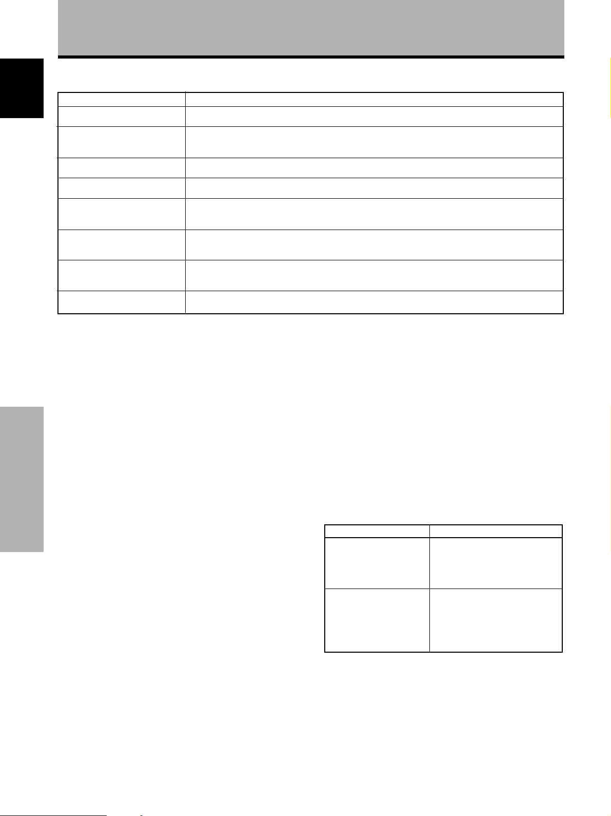
Safety Precautions ............................. i
Before Proceeding ............................. 2
How to Use This Manual .................................... 2
Checking supplied accessories .......................... 3
Part Names and Functions ............... 4
Main unit.............................................................. 4
Remote control unit ............................................ 5
Connection panel ................................................ 6
Installation and Connections ........... 8
Installation of the unit......................................... 8
Connection to a personal computer ................ 10
Audio connections ............................................ 11
Control cord connection ................................... 11
Power cord connection..................................... 12
How to route cables .......................................... 12
Setting Up the System ................... 13
Setup after connection ..................................... 13
Operations ....................................... 14
Selecting an input source................................. 14
Screen size selection ........................................ 16
POWER SAVE .................................................... 17
English
¶ Optional line (sold separately)
(For details, please consult the dealer where this unit was
purchased.)
1 Table top stand : Stand designed specifically for
PDP-502MXE table top placement.
2 Wall installation unit : Wall installation bracket designed as a
wall interface for securing the unit to
various types of wall construction
formats.
CAUTION:
This product may be used only with Model PDK-5001 stands.
Use with other stands may result in instability causing possible injury.
3 Speaker system designed specifically for plasma displays
(width: 7.4 cm)
: With the adoption of a vertical twin system designed with a
2.5 cm domed conical tweeter in the center and newly
developed 4.5 cm wide oval shaped units arranged vertically,
sound field orientation has been greatly improved. Although
the cabinet depth is only 7.4 cm, a rich, dynamic sound is
produced. (When speakers are attached, the operation panel
on this unit is not operable and coil the speaker cord around
the supplied ferrite core and connect the ends to the Rch.)
¶ Designed to conserve energy
This product has been designed to minimize power consumption
when the power is in standby. The value of the power consumption in
standby mode is 0.6 W.
Display Panel Adjustments ............ 18
Adjusting the picture quality............................ 18
Adjusting the display image ............................ 19
Making the PC image brighter (ABL)............... 20
Making the PC image clearer (H/V ENHANCE) .......
21
Resetting the unit to factory set defaults ........ 21
Additional Information ................... 22
Cleaning ............................................................. 22
Inserting the batteries in the remote
control unit ..................................................... 22
Operating range of the remote control unit ... 23
Troubleshooting ................................................ 23
Specifications .................................................... 25
Supplement 1 .................................................... 26
Supplement 2 .................................................... 27
Explanation of Terms ........................................ 27
Before Proceeding
Part Names and Functions
1
En
Page 6

Before Proceeding
How to Use This Manual
This manual is set up to follow the course of actions and
operations in the order that would seem most logical for
someone setting up this unit.
The following example is an actual operation that shows
how one might set the vertical position of the screen. The
screens shown at each step are provided as a visual
guide to confirm that the procedure is proceeding as it
should. Please familiarize yourself with this process
before continuing on with the rest of this manual.
Once the unit has been taken out of the box, and it has
been confirmed that all the parts have been received, it
may be beneficial to look over the section “Part Names
and Functions” starting on page 4 to become acquainted
with the plasma monitor and remote control unit, as their
respective buttons and controls will be referred to
throughout this manual.
The section “Installation and Connections” starting on
page 8 covers all the necessary points regarding
installation of the plasma display and connections to a
personal computer (PC).
The section “Setting Up the System” starting on page 13
covers the necessary on-screen menu settings to
establish correct linkage between the plasma display and
connected components. Depending on the connections
made, this section may or not be necessary.
The remainder of the sections in this manual is dedicated
to the basic operations associated with selecting a source
component up to the more complex operations
associated with adjusting the plasma display picture to
match the requirements of specific components and
personal preferences.
About operations in this manual
Operations in this manual are outlined in step by step
Before Proceeding
numbered procedures. Most of the procedures are
Part Names and Functions English
written in reference to the remote control unit unless the
button or control is only present on the main unit.
However, if a button or control on the main unit has the
same or similar name as that on the remote control unit,
that button can be used when performing operations.
1 Press MENU to display the menu screen.
2 Press 5/∞ to select SCREEN.
MEN
U
E
R
EEN
S
RE
S
R
P
:
MENU O
:
S
EL
U
E
T
AV
ECT
:
H
.
POSI.
V
.
.
V
E
C
LK F
C
LK
R
ESET
F
F
P
SI
OS
I
Z
E
RQ
PHS
.
0
:
0
:
–
––
:
0
:
0
IN
A
M
P
ICT
S
C
A
L
O
P
SETU
M
EN
R
L
WE
U
3 Press 3.
IN
A
M
P
ICT
S
C
AL
O
P
SETU
M
EN
REE
L
WE
U
U
MEN
U
E
R
N
S
RE
S
R
P
:
MENU O
::
S
EL
E
T
AV
ECT
H
.
POSI.
V
.
OS
P
.
V
SI
E
C
LK F
C
LK
R
ESE
F
F
S
ET
:
:
.
I
:
Z
E
:
RQ
:
PHS
T
ADJ UST
–––
0
0
0
0
4 Press 5/∞ to select V. POSI.
IN
A
M
P
ICT
S
C
AL
O
P
SETU
M
EN
REE
L
WE
U
U
MEN
U
E
R
N
S
E
RE
S
AV
R
P
:
MENU O
:
S
ECT
EL
H
.
POSI.
V
.
T
P
.
V
SI
E
C
LK F
C
LK
R
ESET
F
F
SETADJ UST
OS
:
I
Z
E
RQ
PHS
:
0
:
.
0
:
–
––
:
0
:
0
5 Press SET to display the adjustment screen for the
selected item.
REE
C
S
N
V
.P
O
S
ITION
0
S
:EXIT:ADJUST
ET
6 Press 5/∞ to adjust the value.
2
En
Page 7
Checking supplied accessories
Check that the following accessories were supplied.
1 Remote control unit
STANDBY
/ON
SCREEN
VIDEO
SIZE
RGB 1 RGB 2
MUTE
Y/C
VOL
MENU
DISP
SET
CU-V154
Î
2 AA (R6) batteries x 2
Before Proceeding
6 Display stand x 2
English
7 Washer (large) x 2
8 Washer (small) x 2
3 Cleaning cloth (for wiping front panel)
4 Speed clamp x 2
5 Bead band x 2
9 Hex hole bolt x 2
0 Remote control unit case
Use as a holder for the
remote control unit.
When attaching to the
rear of the main unit,
be careful not to cover
the vents.
Before Proceeding
Part Names and Functions
- Ferrite core
Use when connecting
the speakers. Always
coil the Rch speaker
cable around the Ferrite
core. (See page 11 for
coiling procedures.)
÷ Operating Instructions
3
En
Page 8

Part Names and Functions
Main unit
Operation panel on the main unit
Main unit
1
2
STANDBY/ON
3
4
INPUT
MENU
ADJUST
5
6
7
SET
SIZE
DISPLAY
8
9
0
Note
When optional speakers have been connected,
the operation panel on the main unit will not be
operable.
Main unit
1 Display stand
2 Remote control sensor
Part Names and Functions English
Point the remote control toward the remote sensor to
operate the unit (page 23).
Operation panel on the main unit
3 STANDBY/ON indicator
This indicator is red during standby mode, and turns
to green when the unit is in the operation mode
(page 14).
4 STANDBY/ON button
Press to put the display in operation or standby mode
(page 14).
5 INPUT button
Press to select input (page 14).
6 MENU button
Press to open and close the on-screen menu (pages
13 to 21).
7 ADJUST (5 /∞/3/2) buttons
Use to navigate menu screens and to adjust various
settings on the unit.
Usage of cursor buttons within operations is clearly
indicated at the bottom of the on-screen menu display
(pages 13 to 21).
8 SET button
Press to adjust or enter various settings on the unit
(pages 13 to 21).
9 SIZE button
Press to manually select the screen size (page 16).
0 DISPLAY button
Press to view the unit’s current input and setup mode
(page 15).
4
En
Page 9
Part Names and Functions
Remote control unit
1
2
3
4
5
STANDBY
SCREEN
/ON
SIZE
INPUT
VIDEO
Y/C VOL
12
RGB
RGB
(D-sub)
(BNC)
34
MENU
SET
English
6
MUTING
7
8
DISPLAY
9
Î
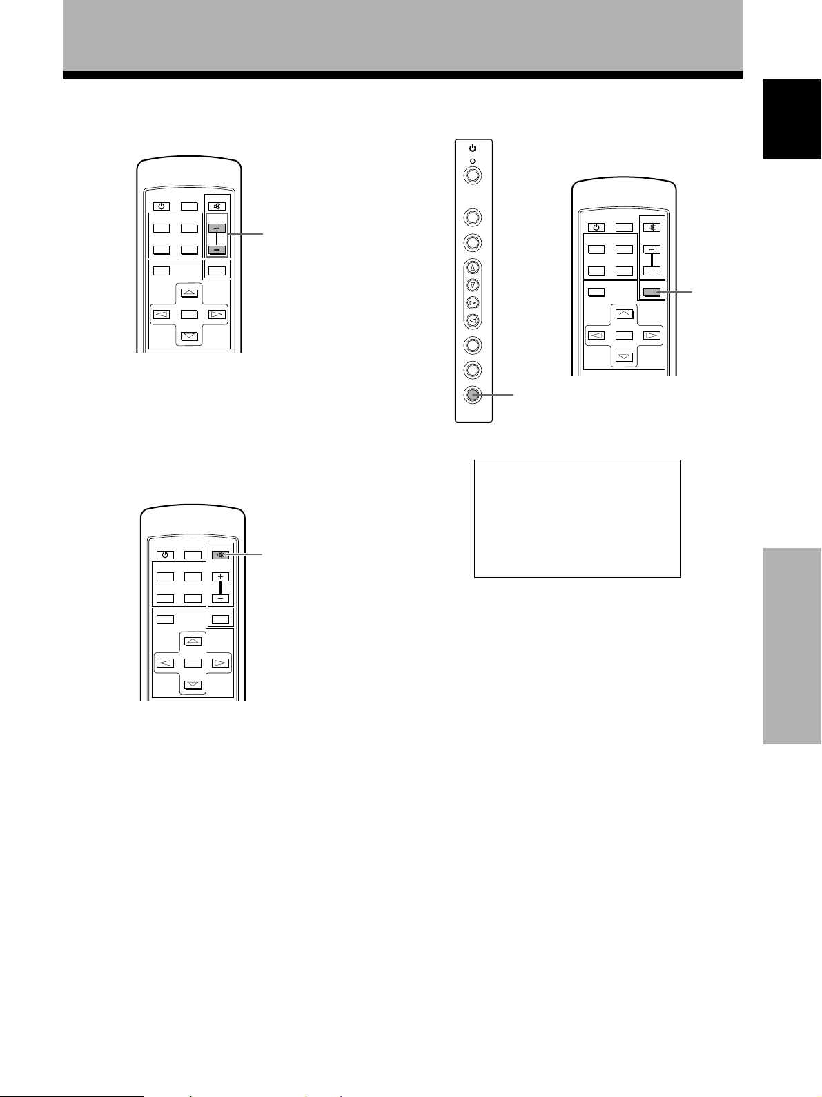
1 STANDBY/ON button
Press to put the unit in operation or standby mode
(page 14).
2 INPUT buttons
Use to select the input (page 14).
3 MENU button
Press to open and close the on-screen menu
(pages 13 to 21).
4 ADJUST (5/∞/3/2) buttons
Use to navigate menu screens and to adjust various
settings on the unit.
Usage of cursor buttons within operations is clearly
indicated at the bottom of the on-screen menu display
(pages 13 to 21).
5 SET button
Press to adjust or enter various settings on the unit
(pages 13 to 21).
6 SCREEN SIZE button
Press to manually select the screen size (page 16).
7 MUTING button
Press to mute the volume (page 15).
8 VOL (+/–) buttons
Use to adjust the volume (page 15).
9 DISPLAY button
Press to view the unit’s current input and setup mode
(page 15).
Part Names and Functions
5
En
Page 10
Part Names and Functions
Connection panel
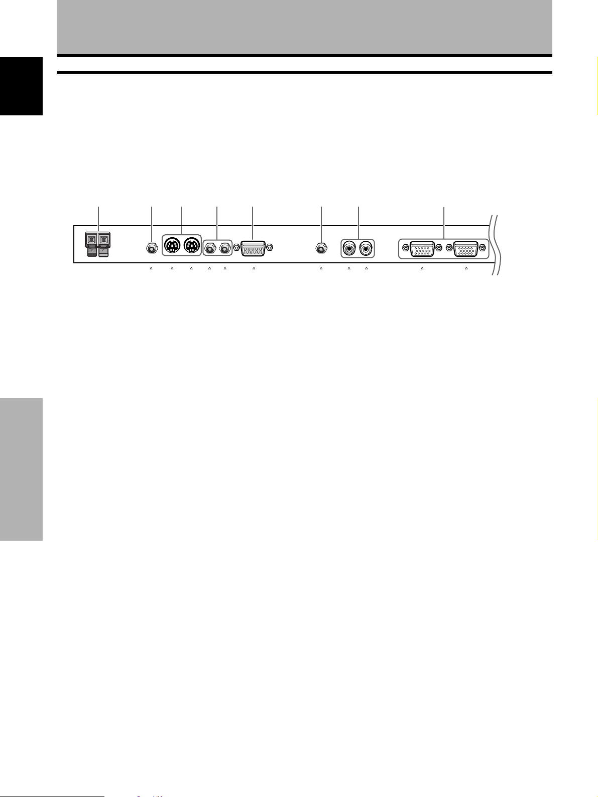
For details regarding a specific connection format, refer to the page written in parenthesis.
1 2 3 4 5 6 7 8
+–
SPEAKER
R
8 Ω – 16 Ω
AUDIO OUTPUT
COMBINATION
1 SPEAKER (R) terminal
For connection of an external right speaker.
Connect a speaker whose impedance is 8 -16 Ω
(page 11).
2 AUDIO OUTPUT (Stereo mini jack)
Use to output the audio of the selected source
component connected to this unit to an AV amplifier
or similar component (page 11).
3 COMBINATION IN/OUT
Part Names and Functions English
DO NOT MAKE ANY CONNECTIONS TO THESE
TERMINALS.
These terminals are used in the factory setup.
4 CONTROL IN/OUT
For connection of PIONEER components that bear the
Î mark. Making CONTROL connection enables
control of this unit as a component in a system
(page 11).
5 RS-232C
DO NOT MAKE ANY CONNECTIONS TO THIS
TERMINAL.
This terminal is used in the factory setup.
IN
OUT
IN
OUT
CONTROL
RS-232C
(INPUT 4)
R – L
(INPUT 3)
AUDIO INPUT
ANALOG
R G B
INPUT4
OUTPUT
ANALOG
(
R G B
(
6 AUDIO INPUT (Stereo mini jack)
Use to obtain sound when INPUT4 is selected.
Connect the audio output jack of components
connected to INPUT4 to this jack (page 11).
7 AUDIO INPUT (Pin jack)
Use to obtain sound when INPUT3 is selected.
Connect the audio output jack of components
connected to INPUT3 to these jacks (page 11).
NOTE: The left audio channel (L) jack is not
compatible with monaural input sources.
8 INPUT4
For connection of a personal computer (PC). Make
sure that the connection made corresponds to the
format of the signal output from the connected
component. Use the INPUT4 OUTPUT terminal to
output the RGB signal to an external monitor or other
component (page 10).
Note: The RGB signal will not be output from the
INPUT4 OUTPUT terminal when the main power of
this unit is off or in standby mode.
6
En
Page 11
Part Names and Functions
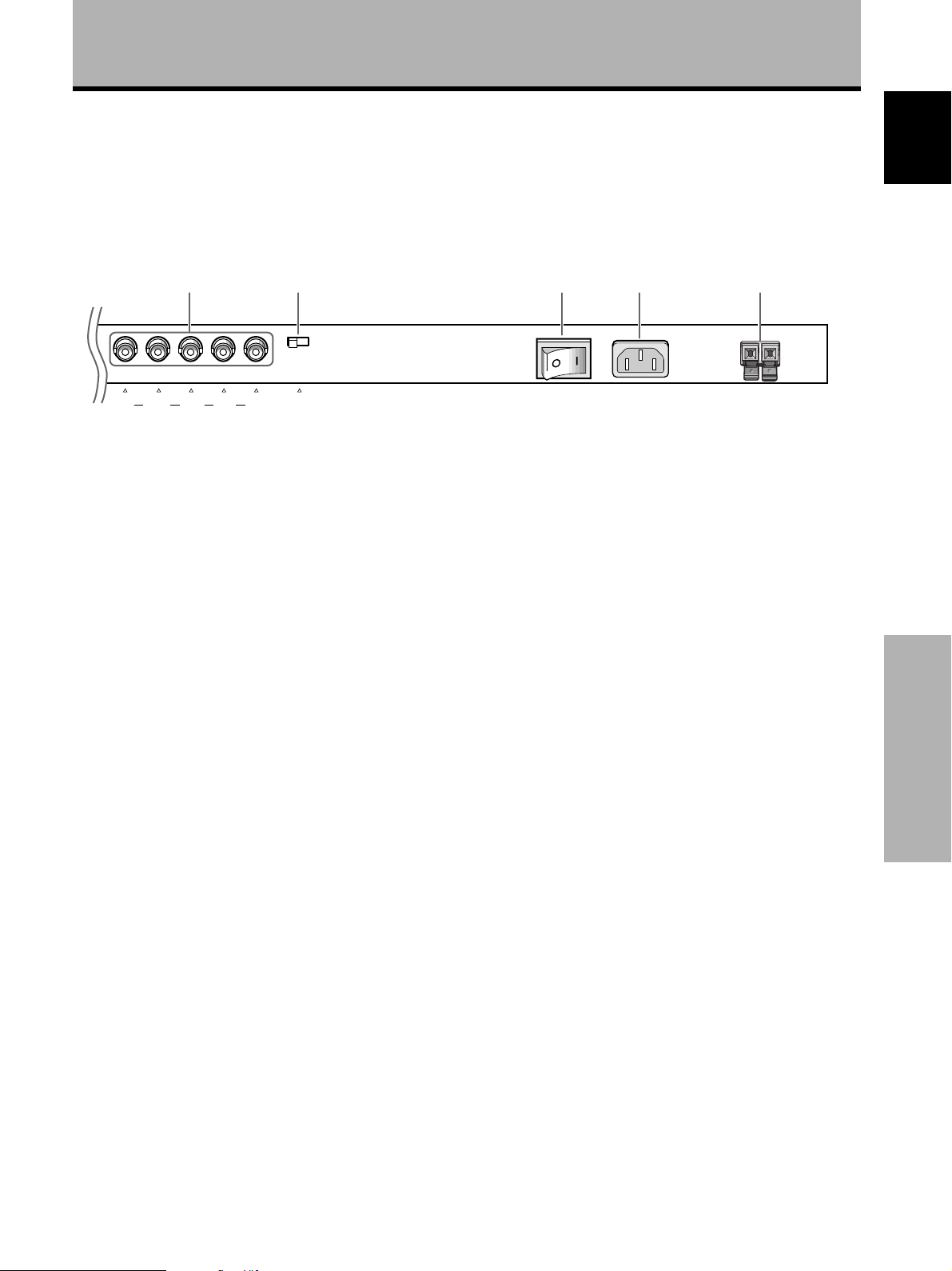
9 0 - = ~
English
G B R
[ON SYNC] [H/V SYNC]
INPUT3
HD VD
75Ωj2.2kΩ
9 INPUT3
For connection of a personal computer (page 10).
0 Synchronizing signal impedance selector switch
Depending on the connections made at INPUT3, it
may be necessary to set this switch to match the
output impedance of the personal computer’s
synchronization signal.
When the output impedance of the personal
computer’s synchronization signal is above 75 Ω, set
this switch to the 2.2 kΩ position (page 10).
- MAIN POWER switch
Use to switch the main power of the unit on and off.
MAIN POWER
OFF ON
AC INLET
SPEAKER
8 Ω – 16 Ω
+–
L
Part Names and Functions
= AC INLET
Use to connect a power cord to an AC outlet (page
12).
~ SPEAKER (L) terminal
For connection of an external left speaker. Connect a
speaker that has an impedance of 8 -16 Ω.
(page 11)
7
En
Page 12
Installation and Connections
Installation of the unit
English
Installation using the supplied display stand
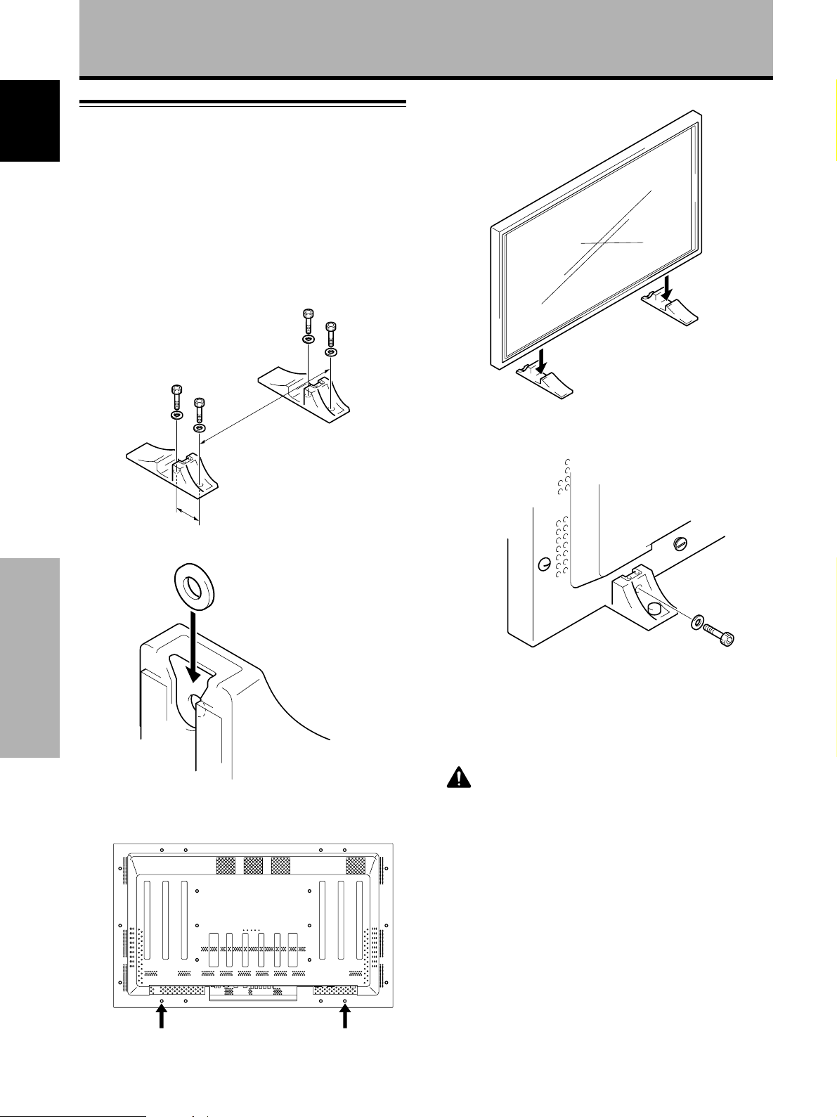
Be sure to fix the supplied stand to the installation
surface.
Use commercially available M8 bolts that are 25 mm
longer than the thickness of the installation surface.
1 Fix the supplied stand to the installation surface at
each of the 4 prepared holes using commercially
available M8 bolts .
Front
4 Set this unit in the stand.
798 mm
Rear
110 mm
2 Insert the supplied washer (large) into the stand.
Installation and Connections
3 Take off the hole rivets A and A’of this unit using
a screwdriver or a coin.
5 Fix this unit using the supplied washer and bolt.
Use a 6 mm hex wrench
to bolt them.
CAUTION
Because this unit weighs about 40 kg and has little depth making
it unstable, please use 2 people or more when packing, carrying
or installing.
AA'
8
En
Page 13
Installation and Connections
Installation using the optional PIONEER stand or
installation bracket
÷ Please be sure to request installation or mounting of this unit
or the installation bracket by an installation specialist or the
dealer where purchased.
÷ When installing, be sure to use the bolts provided with the
stand or installation bracket.
÷ For details concerning installation, please refer to the
instruction manual provided with the stand or installation
bracket.
Installation using accessories other than the
PIONEER stand or installation bracket (sold
separately)
÷ When possible, please install using parts and accessories
manufactured by PIONEER. PIONEER will not he held
responsible for accident or damage caused by the use of parts
and accessories manufactured by other companies.
÷ For custom installation, please consult the dealer where the
unit was purchased, or a qualified installer.
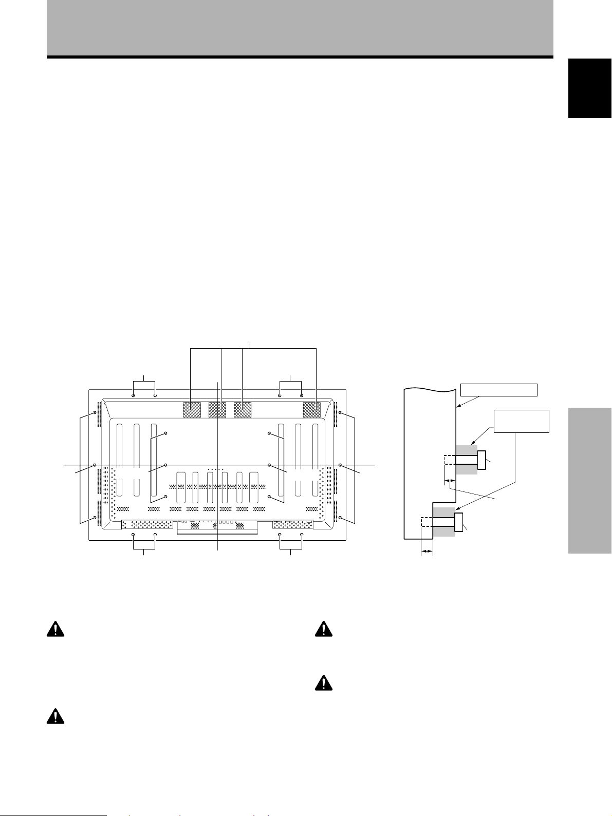
Air vents (fan)
b hole
b hole
Wall-mount installation of the unit
This unit has been designed with bolt holes for
wall-mount installation, etc.. The installation holes that
can be used are shown in the diagram below. (Hole rivets
can be removed by turning with a screwdriver, coin or
similar tool.)
÷ Be sure to attach in 4 or more locations above and
below, left and right of the center line.
÷ Use bolts that are long enough to be inserted 12 mm to
20 mm into the main unit from the attaching surface for
both a holes and b holes. Refer to the side view
diagram below.
÷ As this unit is constructed with glass, be sure to install
it on a flat, unwarped surface.
English
b hole
a hole
Center line
Rear view diagram
CAUTION
To avoid malfunction, overheating of this unit, and possible fire
hazard, make sure that the vents on the main unit are not
blocked when installing. Also, as hot air is expelled from the air
vents, be careful of deterioration and dirt build up on rear surface
wall, etc..
CAUTION
Please be sure to use an M8 (Pitch = 1.25 mm) bolt. (Only this
size bolt can be used.)
b holeb hole
Attaching surface
a hole
Bolt
12 mm to 20 mm
Bolt
a hole
Main unit
Center line
b hole
b hole
12 mm to 20 mm
Side view diagram
CAUTION
Because this unit weighs about 40 kg and has little depth making
it unstable, please use 2 people or more when packing, carrying
or installing.
CAUTION
This unit incorporates a thin design. To ensure safety if vibrated
or shaken, please be sure to take measures to prevent the unit
from tipping over.
Installation
bracket, etc..
Installation and Connections Français
9
En
Page 14
Installation and Connections
INPUT4
ANALOG
R G B
OUTPUT
ANALOG
R G B
(
(
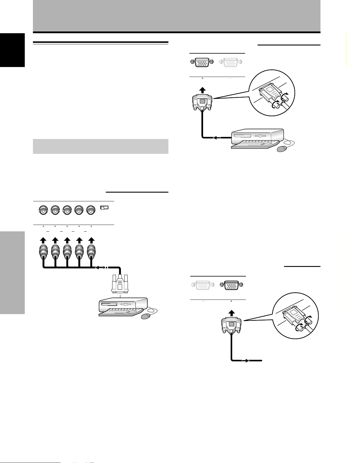
Connection to a personal computer
English
Connection method differs depending on the computer
type. When connecting, please thoroughly read the
computer’s instruction manual.
Before making connections, be sure to make sure that
the personal computer’s power and this unit’s main
power is off.
For the PC input signals and screen sizes that this unit is
compatible with, please refer to Supplement 1 (page 26).
Connection of separate SYNC analog RGB
source
Make separate SYNC connections for a component that
has RGB output separated into 5 output signals: green,
blue, red, horizontal synchronization signal, and vertical
synchronization signal.
When connecting to INPUT3
When connecting to INPUT4
ANALOG
R G B
INPUT4
(
OUTPUT
ANALOG
R G B
(
Connect the cable corresponding to the shape of the
input terminal on this unit and the personal computer’s
output terminal.
Secure by tightening the terminal screws on both units.
After connecting, on-screen setup is necessary.
Please see page 13.
G B R HD VD
INPUT3(ON SYNC) (H/V SYNC)
75Ω j 2.2kΩ
Installation and Connections
When using INPUT3, set the impedance selector switch
to match the output impedance of the connected
component’s synchronization signal.
When the output impedance of the component’s
synchronization signal is above 75 Ω, set this switch to
the 2.2 kΩ position.
On-screen setup is necessary after connection.
Please see page 13.
Note
Depending on the type of computer model being connected, a
conversion connector or adapter etc. provided with the computer
or sold separately may be necessary.
For details, please read your PC’s instruction manual or consult
the maker or nearest dealer of your computer.
When connecting to INPUT4 (OUTPUT)
To an external monitor
With this unit, it is possible to output the RGB signal to an
external monitor or other component from the INPUT4
OUTPUT terminal.
10
En
Note
An RGB signal will not be output from the INPUT4 OUTPUT
terminal when the main power of this unit is off or in standby.
Page 15
Installation and Connections
CONTROL
IN
OUT
CONTROL
IN
OUT
CONTROL
IN
OUT
CONTROL
IN OUT
Audio connections
Before making connections, be sure to check that the
component’s power and the unit’s main power is off.
Connecting the speakers
This unit is equipped with speaker output jacks for
connection to the speaker system (not supplied) specially
designed for use with this unit. Refer to the illustrations
below when making connections to the speaker terminals
on this unit.
Twist exposed
wire strands
10 mm
Note
When making speaker connections, be sure to match the
polarities (+ and –) of the speaker terminals on this unit and the
corresponding terminals on the speakers. If the polarity is
reversed, the sound will be unnatural and lack bass. Coil the
speaker cable with the supplied ferrite core and connect the
ends to Rch (connect the ferrite core as close as possible to the
Rch speaker output jack).
together.
Push tab to the open
position, and insert the
wire. Then, close tab
firmly to secure the wire
in place.
Control cord connection
When control cord connections are made, remote control
operation of connected PIONEER components that bear
the Î logo mark is done through the remote sensor on
this unit.
When the connection is made to the CONTROL IN jack
on another unit, the remote sensor of that component will
no longer receive signals. Point the remote control unit of
the connected component at the remote control sensor
on this unit to control.
Notes
÷ Make sure the power is turned off when making
connections.
÷ Please complete all component connections before
making control cord connections.
Main unit
English
As close as possible
To the Rch speaker
Making connections to the audio inputs on this
unit
This unit features two audio inputs and one audio output.
The following chart shows the inputs and the
corresponding audio input jacks.
Video
input
INPUT3
INPUT4
Audio input jacks Sound output
Pin jacks
(L/R)
Stereo mini jack
(L/R)
Sound of the selected input
is output from the
• SPEAKER terminals
• Stereo mini jacks (L/R).
The control cables (not
supplied) are monaural
cables with mini plugs (no
resistance).
Installation and Connections Français
11
En
Page 16
Installation and Connections
Power cord connection
English
Connect a power cord after all component connections
have been completed.
PDP-502MXE power cord ratings
Cord .......................... Cross-sectional area 3 x 1.0 mm
(According to CEE 13)
Connector ................................................... 10 A, 250 V
(According to EN60320 Sheet C13)
Plug ................................International use (10 A, 250 V)
Example:
UK : UK 13 Amp Plug with rated 13 Amp fuse
(According to BS1363)
EURO : 10 A/16 A 250 V (According to CEE 7, 1 V)
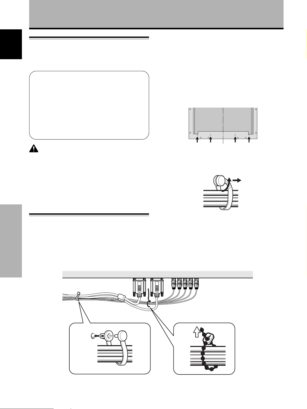
1 Organize cables together using the provided
speed clamps.
Insert 1 into an appropriate hole on the rear of the
unit, then snap 2 into the back of 1 to fix the clamp.
Speed clamps are designed to be difficult to undo
once in place. Please attach carefully.
2
To attach the speed clamps to the main unit
Connect the speed clamps using the 4 holes marked with
• below, depending on the situation.
CAUTION
÷ Do not use a power supply voltage other than that indicated
(AC 100 - 240 V, 50/60 Hz) as this may cause fire or electric
shock.
÷ For the plasma display, a three-core power cord with a ground
terminal is used for efficiency protection. Always be sure to
connect the power cord to a three-pronged grounded outlet
and make sure that the cord is properly grounded. If you use a
power source converter plug, use an outlet with a ground
terminal and screw down the ground line.
How to route cables
Speed clamps and bead bands are included with this unit
for bunching cables together. Once components are
connected, follow the following steps to route cables.
Installation and Connections
To remove speed clamps
Using pliers, twist the clamp 90° and pull it outward.
In some cases the clamp may have deteriorated over
time and may be damaged when removed.
2 Bunch separated cables together and secure
them with the provided bead bands.
Note
Cables can be routed to the right or left.
* As viewed from the rear of the display.
12
En
1
1
2
2
Page 17
Setting Up the System
Setup after connection
After components have been connected to INPUT3 or
INPUT4, on-screen setup is necessary.
Follow the procedure described below and make settings
as they apply to the type of components connected.
1 Switch MAIN POWER on the connection panel to
the on position to turn on the unit’s main power.
The STANDBY/ON indicator lights red.
2 Press STANDBY/ON to put the unit in the
operation mode.
The STANDBY/ON indicator turns green.
3 Select INPUT3 or INPUT4.
4 Press MENU to display the menu screen.
The menu screen appears.
5 Press 5/∞ to select SET UP, and press SET.
MEN
U
R
N
R
P
U
E
S
E
T
S
AV
E
IN
A
M
P
ICT
S
C
REE
ALLRE
O
WE
P
SETU
G ON SYNC setup (CLAMP)
The RGB video signal is normally composed of 5 signals:
R, G, B, HD and VD. With G ON SYNC connection,
however, the signal is composed of 3 signals: R, G (G, HD
and VD combined) and B.
If the personal computer being used is a model where
G ON SYNC connection is carried out, on-screen setup is
necessary.
Setup of G ON SYNC (CLAMP) connection
1 Press MENU to display the menu screen.
The menu screen appears.
2 Press 5/∞ to select SET UP, and press SET.
IN
A
M
P
ICT
S
C
REE
ALLRE
O
WE
P
SETU
U
M
EN
3 Press 5/∞ to select CLAMP.
U
MEN
U
E
R
N
S
E
S
AV
R
P
:
MENU O
:
S
ECT
EL
T
E
F
F
:
S
ET
X
N
E
T
English
:
U
M
EN
MENU O
:
S
ECT
EL
F
F
:
S
ET
X
N
E
T
6 Press 5/∞ to select SETTING.
TU
E
S
P
I
T
ERM
S
E
TTI
G
SI
L
AM
C
ABL
H.ENHANCE
ENHANCEV.
EX I T
:
S
L
A
N
G
N
N
AL
P:M
ECT
EL
:BN
:PC
:
R
G
O
OF
:
:
:
S
C
B
DE
F
0
0
ET
1
:
C
A
E
H
NG
7 Press SET to select “PC”.
Depending on the input signal, this unit may not be
able to make the correct setting. Make sure that this
setting is set to “PC”.
Note
Steps 6 to 7 are necessary when inputting a signal of horizontal
frequency 31.5 kHz/vertical frequency 60 Hz.
When inputting a signal of horizontal frequency 48.4 kHz/vertical
frequency 60 Hz, "1024 x 768" or "1280 x 768" must be set at the
"PC" settings, depending on the input signal.
For signals of other frequencies, settings are done automatically,
and therefore cannot be performed.
8 When the setup is completed, press MENU to exit
the menu screen.
Notes
÷ Make this setup for each input (INPUT3 and INPUT4).
÷ Please refer “G ON SYNC (CLAMP)” on this page for details
concerning G ON SYNC setup.
TU
E
S
T
S
SI
C
A
H
V
EX
ERM
E
L
B
.
.
:
P
I
N
N
TTI
G
N
AL
AM
P
L
ENHAN
ENHAN
I
T
S
ECT
EL
L
C
:BN
A
G
:PC
:
R
B
G
O
DE1
:M
F
F
:
O
:
CE
CE
0
:
0
:
S
C
A
E
H
ET
NG
4 Press SET to select MODE2.
Mode selection will change as follows each time SET
is pressed.
3 MODE1 (Normal connection)
MODE2 (G ON SYNC connection) 2
5 When the setup is completed, press MENU to exit
the menu screen.
Notes
÷ Make this G ON SYNC setting for each applicable input
(INPUT3 and INPUT4).
÷ When using this setup, be sure to carefully check the signal
output of the personal computer you are using. For details,
please refer to the instruction manual supplied with the
personal computer you are connecting.
÷ If the screen becomes bright and turns a greenish color, set
CLAMP to MODE2.
÷ G ON SYNC connection is carried out on some Macintosh
computers.
13
Setting Up the System Français
En
Page 18

Operations
Selecting an input source
English
This section explains the basic operation of this unit.
Outlined on the following pages is how to turn the main
power on and off, put this unit in the operation or standby
mode and how to select connected components.
Note
INPUT1 and INPUT2 on the remote control unit can only be used
when the optional video box, PDA-5001, is connected to this unit.
Before you begin, make sure you have:
•
Made connections between this unit and a personal
computer as described in the section “Installation and
Connections” starting on page 8.
• Set up the on-screen menu to input signals from
components connected to INPUT3 and INPUT4 as
described in the section “Setting Up the System” on
page 13.
STANDBY/ON
2,5
INPUT
Operations
MENU
ADJUST
SET
SIZE
DISPLAY
3
2,5
STANDBY
SCREEN
INPUT
(D-sub)
MENU
SIZE
Y/C
RGB
SET
MUTING
DISPLAY
/ON
VIDEO
12
RGB
3
(BNC)
34
VOL
3 Press the appropriate INPUT button on the remote
control unit or INPUT on the main unit to select
the input.
On the main unit, input changes each time INPUT is
pressed as follows.
3 INPUT3
INPUT4 2
• Input cannot be changed when a menu screen is
displayed.
• When a signal from a personal computer is input, if
the signal is not compatible with this unit, “OUT OF
RANGE” will appear on the screen.
4 Use VOLUME +/– on the remote control unit to
adjust the volume.
If no audio connections are made to this unit, this step
is not necessary.
5 When viewing is finished, press STANDBY/ON
to put the unit in standby mode.
The STANDBY/ON indicator will blink and then remain
lit (red) indicating that the standby mode is engaged.
Operation is not possible while the STANDBY/ON
indicator is blinking (red).
6 Switch MAIN POWER on the main unit to the off
position to turn the main power off.
4
CAUTION
Please do not leave the same picture displayed on the screen for
a long time. Doing so may cause a phenomenon known as
“screen burn” which leaves a ghost, or residual, image of the
picture on the screen.
Operation panel of
the main unit
Remote control unit
1 Switch MAIN POWER on the main unit to the on
position to turn the main power on.
The STANDBY/ON indicator lights red.
2 Press STANDBY/ON to put this unit in the
operation mode.
The STANDBY/ON indicator turns green.
14
En
Page 19
Operations
To adjust the volume
STANDBY
SCREEN
INPUT
MENU
SIZE
Y/C VOL
RGB
(D-sub)
SET
MUTING
VOL +/–
DISPLAY
/ON
VIDEO
12
RGB
(BNC)
34
Use VOL + or VOL – to adjust the volume of the
connected speakers.
To mute the sound
To confirm display settings
STANDBY/ON
INPUT
MENU
ADJUST
SET
SIZE
DISPLAY
DISPLAY
STANDBY
SCREEN
/ON
INPUT
VIDEO
12
RGB
(D-sub)
(BNC)
34
MENU
F
H:
F
V:
MUTING
SIZE
Y/C VOL
RGB
DISPLAY
SET
8
4
.
0
6
.0H
U
4
K
T4INP
H
English
DISPLAY
Z
Z
STANDBY
SCREEN
INPUT
MENU
SIZE
Y/C VOL
RGB
(D-sub)
SET
MUTING
DISPLAY
MUTING
/ON
VIDEO
12
RGB
(BNC)
34
Press MUTING on the remote control unit.
Press MUTING again to restore the sound.
Muting is automatically canceled in about 8 minutes if no
operations are performed during that time, and the
volume level is adjusted to the minimum level.
Press VOL + or VOL – to adjust the volume at a desired
level.
F
ULL
Press DISPLAY.
The currently selected input, screen size and vertical and
horizontal frequencies will be displayed for approximately
3 seconds.
Note
The displayed vertical and horizontal frequencies are
approximations, and may be slightly different from the actual
values.
Operations
15
En
Page 20
Operations
Screen size selection
English
Moving the screen position
upward or downward
Changing the screen size
The size of the picture or the picture’s range projected on
the screen can be changed between 4 screen sizes
described in the table on this page.
Press SCREEN SIZE to select the size.
The screen size changes each time SCREEN SIZE on the
remote control, or SIZE on the unit is pressed as follows.
For PC signals
3 ORIGINAL 3 4:3 NORMAL
FULL 2ZOOM 2
(For screen sizes when the video signal of a personal
computer is input, please see Supplement 1 on page 26.)
1 ORIGINAL
The input signal and the screen maintain a dot to line ratio
of 1:1 and is thus highly faithful to the source.
During personal computer input (1280 x 1024/60Hz only),
when the ZOOM setting is selected, the position of the
screen can be adjusted by using 5/∞.
3 FULL
The display is presented with a widescreen aspect ratio
of 16:9 and fills the entire screen.
480 lines
A
Operations
(Illustration shows 640 x 480 input.)
2 4:3 NORMAL
The display fills the screen as much as possible without
altering the aspect ratio of the input signal.
640 dots
1280 dots
A
768 lines
A
4 ZOOM
The ZOOM setting is available only during personal
computer input (1280 x 1024/60 Hz only).
The input signal and the screen maintain a dot to line ratio
of 1:1. Display is highly faithful to the source. However, in
order to maintain the 1:1 ratio, a portion of the display will
not appear on the screen.
768 lines
1024 lines
Use 5/∞ to adjust the position of the video image on the
screen.
16
En
Page 21
POWER SAVE
Using the POWER SAVE function of this unit, the power
mode can be automatically put in standby mode when a
video or computer signal has not been detected.
(An indication will appear on the screen before the
standby mode is engaged).
1 Press MENU to display the menu screen.
2 Press 5/∞ to select POWER SAVE, and press SET.
MEN
U
REE
R
:
U
MENU O
:
S
R
N
P
EL
E
S
S
U
E
T
AV
ECT
E
F
F
:
S
ET
X
N
E
T
IN
A
M
P
ICT
S
C
ALLRE
O
WE
P
SETU
M
EN
3 Press 5/∞ to select “PC”.
Operations
5 When the setup is finished, press MENU to exit
the menu screen.
Note
The POWER SAVE setting is common to INPUT3 and INPUT4.
To put the unit in operation mode again
Press STANDBY/ON on the main unit or remote
control unit.
If “MODE 2” is selected for PC input, resuming PC
operation or pressing INPUT on the main unit or remote
control unit can also put the unit in operation mode again.
English
RSA
O
:
MOD
:
MOD
T
ECT
EL
VE
E1
E
S
2
ET
:
C
A
E
H
NG
WE
O
P
V
IDE
P
C
E
XI
:
S
4 Press SET to select the POWER SAVE mode.
The PC POWER SAVE mode changes each time SET
is pressed as follows.
3 OFF
MODE2 2
÷ When “OFF” is selected, this unit will stay in
operation mode regardless of whether a
synchronization signal is input or not.
÷ When “MODE1” is selected, this unit will be put in
standby mode automatically if no new
synchronization signal is input for 8 minutes.
÷ When “MODE2” is selected, this unit will be put in
the power conservation standby automatically if no
new synchronization signal is input. However, if the
synchronization signal is restored, this unit is put
back in operation mode.
MODE1 2
Operations
17
En
Page 22

Display Panel Adjustments
Adjusting the picture quality
English
1 Press MENU to display the menu screen.
2 Press 5/∞ to select PICTURE, then press 3.
MEN
U
E
R
N
S
S
R
P
:
MENU O
:
S
EL
U
MEN
U
E
R
N
S
E
S
AV
R
P
:
MENU O
:
S
ECT
EL
U
E
T
AV
ECT
T
E
E
F
C
B
R
G
B
R
F
F
S
C
ON
B
RI
R
G
B
R
ESET
F
S
ET
ON
R
T
RI
H
G
L
V
E
L
V
E
L
V
E
ESET
:ADJUS
ET
R
T
H
G
L
V
E
L
V
E
L
V
E
:ADJUS
:
ST
A
:
T
:
L
E
:
L
E
:
L
E
T
:
ST
A
:
T
:
L
E
:
L
E
:
L
E
T
A
IN
M
P
ICT
S
C
REE
ALLRE
O
WE
P
SETU
U
M
EN
3 Press 5/∞ to select the adjustment item, then
press SET.
A
IN
M
P
ICT
S
C
REE
ALLRE
O
WE
P
SETU
U
M
EN
4 Press 2/3 to adjust the picture quality as desired.
PICTURE mode adjustment items
Below are brief descriptions of the options that can be set
in the PICTURE mode.
CONTRAST ············· Adjust according to the surrounding
brightness so that the picture can be
seen clearly.
BRIGHT ··················· Adjust so that the dark parts of the
0
0
0
0
0
R LEVEL ·················· Adjust the amount of red in the
G LEVEL ·················· Adjust the amount of green in the
picture can be seen clearly.
picture.
picture.
B LEVEL ·················· Adjust the amount of blue in the
picture.
To reset PICTURE mode settings to the default
If settings have been adjusted excessively or the picture
0
0
0
0
0
on the screen no longer appears natural, it may prove
more beneficial to reset the PICTURE mode to default
settings instead of trying to make adjustments under
already adjusted conditions.
1 In step 3 in the previous procedure, press 5/∞ to
select RESET, then press SET.
CT
I
P
RUE
CTU
I
P
C
Display Panel Adjustments
Pressing SET returns the display to the step 3 screen.
ON
RE
AST
R
T
0
S
:EXIT:ADJUST
ET
5 When the setup is finished, press MENU to exit
the menu screen.
Note
Make these adjustments for both INPUT3 and INPUT4.
ET?
A
DJUST
Y
:
S
ECTS
EL
E
R
ES NO
ET:EXI
S
T
2 Press 2 to select YES, and press SET.
All PICTURE mode settings are returned to the factory
set default.
18
En
Page 23
Adjusting the display image
1 Press MENU to display the menu screen.
2 Press 5/∞ to select SCREEN, then press 3.
MEN
U
REE
R
:
U
MENU O
:
S
MEN
U
REE
R
:
U
MENU O
:
S
N
R
N
P
EL
R
N
P
EL
E
S
S
E
S
S
U
E
T
AV
ECT
U
E
T
AV
ECT
:
H
.
POSI.
V
.
.
I
OS
P
.
V
SI
C
LK F
C
LK
R
ESET
F
H
.
V
.
.
V
C
LK F
C
LK
R
ESET
F
S
ET
Z
E
RQ
PHS
POSI.
I
OS
P
SI
Z
E
RQ
PHS
:ADJUS
.
E
F
E
F
:
:
:
:
:
:
:
:
:
–––
––
T
0
0
0
0
0
0
–
0
0
A
IN
M
P
ICT
S
C
ALLRE
O
WE
P
SETU
M
EN
“– – –” is displayed if the adjustment is not available.
3 Press 5/∞ to select the adjustment item, then
press SET.
A
IN
M
P
ICT
S
C
ALLRE
O
WE
P
SETU
M
EN
4 Press 2/3 to carry out the adjustment.
REE
C
S
Display Panel Adjustments
SCREEN mode adjustment items
Below are brief descriptions of the options that can be set
in the SCREEN mode.
H.POSITION ············ Adjust the picture’s position to the
left or right.
V.POSITION ············· Adjust the picture’s position upward
or downward.
CLK FREQ. ·············· Adjust letter breakup or noise on the
screen. This setting adjusts the
unit’s internal clock signal frequency
that corresponds to the input video
signal.
CLK PHASE ············· Adjust so that there is minimum
flicker of screen letters or color
misalignment. This setting adjusts
the phase of the internal clock signal
adjusted by the CLK FREQ. setting.
Notes
÷ When CLK FREQ. adjustment is carried out, the H.POSITION
setting may have to be re-adjusted.
÷ If the adjustment items in the SCREEN mode are adjusted
excessively, the picture may not be displayed properly.
To reset SCREEN mode settings to the default
If settings have been adjusted excessively or the picture
on the screen no longer appears natural, it may prove
more beneficial to reset the SCREEN mode to default
settings instead of trying to make adjustments under
already adjusted conditions.
1 In step 3 in the previous procedure, press 5/∞ to
select RESET, then press SET.
English
H
.P
O
S
ITION
0
S
:EXIT:ADJUST
ET
Use 5/∞ for the adjustments of V.POSITION .
Pressing SET returns the display to the step 3 screen.
5 When adjustment is finished, press MENU to exit
the menu screen.
Note
Make these adjustments for both INPUT3 and INPUT4.
RE
C
S
NE
A
DJUST
Y
:
S
ECTS
EL
E
R
ES NO
ET:EXI
S
ET?
T
2 Press 2 to select YES, and press SET.
All SCREEN mode settings are returned to the factory
set default.
Display Panel Adjustments
19
En
Page 24
Display Panel Adjustments
Making the PC image brighter
English
(ABL)
Set this mode to “ON” to brighten the image during PC
signal input. When ABL is set to “ON”, the brightness of
the image will change according to changes in the input
signal. If you are bothered by changes to brightness
during operation, set this mode to “OFF”.
1 Press MENU to display the menu screen.
The menu screen appears.
2 Press 5/∞ to select SET UP, then press SET.
MEN
U
REE
R
:
U
MENU O
:
S
R
N
P
EL
E
S
S
U
E
T
AV
ECT
E
F
F
:
S
ET
X
N
E
T
IN
A
M
P
ICT
S
C
ALLRE
O
WE
P
SETU
M
EN
4 Press SET to set the mode to “ON”.
“ON” is set when this unit is shipped from the
factory.
TU
E
S
T
S
SI
C
A
H
V
EX
ERM
E
L
B
.
.
:
P
I
N
N
TTI
G
N
AL
AM
P
L
ENHAN
ENHAN
I
T
S
ECT
EL
A
G
L
CE
CE
:BN
:PC
:
R
:M
:
O
:
:
S
ET
G
O
N
C
B
DE1
0
0
:
C
A
E
H
NG
Each time SET is pressed, the settings change in the
following order.
3 ON
OFF 2
5 When the setup is finished, press MENU to exit
the menu screen.
Note
Make the setting for each input (INPUT3 or INPUT4).
3 Press 5/∞ to select ABL.
TU
E
S
T
ERM
S
E
TTI
G
SI
L
AM
C
B
L
A
.
ENHAN
H
ENHAN
.
V
I
EX
:
S
Display Panel Adjustments
N
T
EL
P
I
AL
P
A
N
G
N
ECT
L
CE
CE
:BN
:PC
:
R
:M
:
O
:
:
S
ET
G
O
F
C
B
DE1
F
0
0
:
C
A
E
H
NG
20
En
Page 25
Display Panel Adjustments
Making the PC image clearer (H/V ENHANCE)
Resetting the unit to factory set
defaults
Adjust H/V ENHANCE to view a clear image during PC
signal input.
1 Press MENU to display the menu screen.
The menu screen appears.
2 Press 5/∞ to select SET UP, then press SET.
IN
A
M
P
ICT
S
C
REE
ALLRE
O
WE
P
SETU
U
M
EN
U
MEN
U
E
R
N
S
E
S
AV
R
P
:
MENU O
:
S
ECT
EL
T
E
F
F
:
S
ET
X
N
E
T
3 Press 5/∞ to select H. ENHANCE or V. ENHANCE,
then press SET.
TU
E
S
P
T
S
SI
C
A
H
V
EX
ERM
E
L
B
.
.
:
I
N
N
TTI
G
N
AL
AM
P
L
ENHAN
ENHAN
I
T
S
ECT
EL
A
G
CE
CE
C
L
:BN
:PC
:
R
B
G
O
DE1
:M
F
F
:
O
:
0
:
0
:
S
C
A
E
H
ET
NG
1 Press MENU to display the menu screen.
The menu screen appears.
2 Press 5/∞ to select ALL RESET, then press SET.
3 Press 2 to select YES, then press SET.
All settings of the PICTURE and SCREEN modes are
returned to the default settings (factory set defaults).
IN
A
M
P
ICT
S
C
REE
ALLRE
O
WE
P
SETU
U
M
EN
L
L
A
U
MEN
U
E
R
N
S
E
S
AV
R
P
:
MENU O
:
S
ECT
EL
SE
E
R
T
A
DJUST
:
S
ECTS
EL
T
E
F
F
S
ET
L
Y
ES NO
:
X
N
E
T
ET?
S
RELA
ET:EXI
English
T
4 Press 2/3 to adjust.
TU
E
S
H
.E
N
P
ANCE
H
0
S
:EXIT:ADJUST
ET
Pressing SET returns the display to the step 3 screen.
5 When the setup is finished, press MENU to exit
the menu screen.
Note
H. ENHANCE or V. ENHANCE mode adjusting is only possible
during PC signal input.
Make the adjustment for each input (INPUT3 and INPUT4).
Display Panel Adjustments
21
En
Page 26
Additional Information
Cleaning
English
Regular cleaning will extend the life and performance of
this unit. The recommended way to clean the display and
related parts is described below.
Before cleaning, be sure to unplug the power cord from
the power outlet.
Cleaning the display panel body and remote
control
Do not under any circumstances use solvents such as
benzine or thinner for cleaner. Use of such liquids may
cause deterioration or peeling of paint from the display or
remote control unit.
Wipe the display and remote control gently with a soft
cloth. In the case of excessive dirt buildup, dampen a soft
cloth with a diluted neutral cleaning detergent and after
wringing the cloth thoroughly, wipe the component and
then dry it with a dry soft cloth.
Cleaning the screen
After dusting, wipe the screen gently using the supplied
cleaning cloth or a soft cloth. Do not use tissue or a rough
cloth. As the surface of the screen is easily scratched, do
not rub it or hit it with a hard object.
Cleaning the vents
As a general rule, use a vacuum cleaner about once a
month to clean the vents on the rear panel of the display
of dust buildup (set the vacuum cleaner to its weakest
setting when doing this).
Using the unit without cleaning it of dust will cause the
internal temperature to increase, resulting in possible
breakdown or fire.
Additional Information
Vents
Vents
Vents
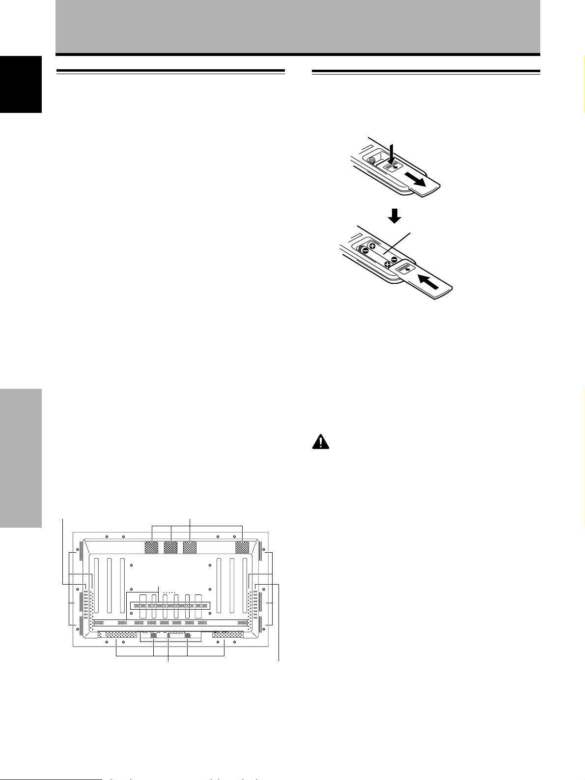
Inserting the batteries in the remote
control unit
While pressing down
lightly, slide in the
direction of the arrow.
Two AA (R6)
batteries
When handling the remote control unit
¶ Do not drop or shake the remote control.
¶ Do not use the remote control unit in a location subject to
direct sunlight, heat radiation from a heater, or in a place
subject to excessive humidity.
¶ When the remote control unit’s batteries begin to wear out,
the operable distance will gradually become shorter. When this
occurs, replace all batteries with new ones as soon as
possible.
CAUTION
¶ Insert batteries so that the plus (+) and minus (–) sides are
aligned according to the markings in the battery case.
¶ Do not mix new batteries with used ones.
¶ The voltage of batteries may differ even if they are the same
shape. Please do not mix different kinds of batteries together.
¶ When not using the remote control unit for a long period of
time (1 month or more), remove the batteries from the remote
control unit to prevent leaking of battery fluid. If battery liquid
has leaked, thoroughly wipe the inside of the case until all
liquid is removed, and then insert new batteries.
¶ Do not charge, short, disassemble or throw the provided
batteries in a fire.
22
En
Vents
Vents
Page 27
Additional Information
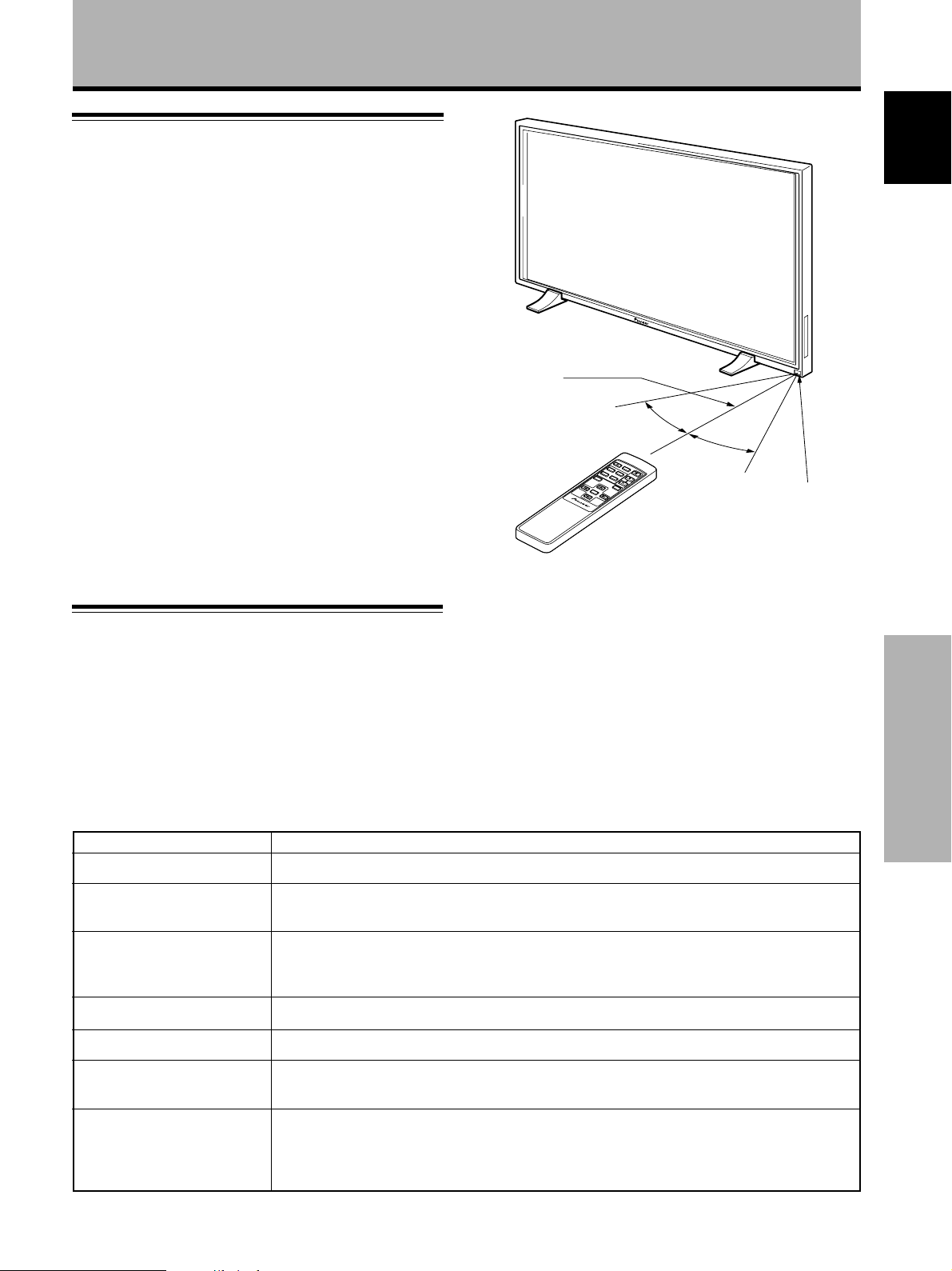
Operating range of the remote
control unit
When operating the remote control unit, point it at the
remote sensor (Î) located on the front panel of the main
unit. The remote control unit is operable up to 23 feet
(7 m) from the unit and within a 30 angle on each side of
the sensor.
If you are having difficulty with operation of the
remote control unit
¶ The remote control unit may not operate if there are objects
placed between it and the display.
¶ Operational distance will gradually become shorter as the
batteries begin to wear out, replace weak batteries with new
ones as soon as possible.
¶ This unit discharges infrared rays from the screen. Placing a
video deck or other component that is operated by an infrared
remote control unit near this unit may hamper that
component’s reception of the remote control’s signal, or
prevent it from receiving the signal entirely. Should this occur,
move the component to a position further away from this unit.
¶ Depending on the installation surroundings, this unit’s remote
control unit may be influenced by the infrared rays discharged
from the plasma display, hampering reception of its rays or
limiting its operational distance. The strength of infrared rays
discharged from the screen will differ according to the picture
displayed.
7 m (23 feet)
English
30˚
STANDBY
/ON
SCREEN
VIDEO
SIZE
RGB 1 RGB 2
MUTE
Y/C
VOL
MENU
DISP
SET
CU-V154
Î
30˚
Remote Sensor
Troubleshooting
What may at first seem to be an malfunction, may be
remedied with a quick check.
Please check to see if a warning is displayed on the
screen. If displayed, refer to page 24 and check the
mode. If there is no display check to see if the problem is
listed below. The problem may also be caused by
something other than this unit so please also check the
other components being used such as a video deck. If the
problem can still not be solved please consult the dealer
where this unit was purchased.
General Problems
Problem Possible Solution
• No power
• Unit cannot be operated.
• Remote control does not
operate.
• Picture is cut off.
• Strange color, light color, or
dark, or color misalignment
• Power is suddenly turned
off.
• No picture
• Is the power cord disconnected? (page 12)
• Has the MAIN POWER switch been switched on? (page 7)
• External influences such as lightning, static electricity, etc., may cause improper operation. In this
case, operate the unit after first turning the main power on/off, or unplugging the power cord and
re-plugging it in after 1 to 2 minutes.
• Are batteries inserted with polarity (+, –) correctly aligned? (page 22)
• Are batteries worn out? (Replace with new batteries).
• Is the plug inserted in the CONTROL IN terminal? Because reception of the remote control’s
signal will not be possible if the plug is inserted, please check connections (page 11).
• Is the selected screen size correct? Switch to another screen size (page 16).
• Are SCREEN mode adjustments such as picture size made correctly? (page 19).
• Adjust the picture tone (page 18).
• Is the room too bright? The picture may look dark in a room that is too bright.
• The unit’s internal temperature has increased. (Air vents are blocked.)
Remove any objects blocking vent or clean (page 22).
• Is the POWER SAVE mode set to “MODE1” or “MODE2”? (page 17)
• Are all connections correct? (page 10)
• Has setup been done correctly after connection? (page 13)
• Is the correct input selected? (page 14)
• Is a non-compatible signal being input? (page 26)
• Is picture adjustment correct? (page 18)
Additional Information
23
En
Page 28
Additional Information
Problems commonly mistaken as breakdown
English
• The screen is displayed in a
small size.
• Letter breakup on screen.
• A sharp sound is sometimes
heard from the cabinet.
• Bright portions of image
appear to be losing intensity.
• Speckles or noise appears on
screen.
• Stripes appear on the screen.
• Operation is not possible.
• Sound is heard from inside
the unit.
Problem Possible Solution
• Check the input signal compatibility chart (page 26).
• Is the correct screen size selected? (page 16)
• Adjust using “SCREEN” mode on the menu screen (page 19).
If there is still no improvement, this unit may be limiting the displayable range. Check the
personal computer input signal compatibility chart (page 26).
• Expansion/contraction caused by surrounding temperature change may result in sound being
heard from the cabinet. This is not a malfunction.
• When the input signal’s level is too high, the bright portions may appear to be losing their intensity.
Increase the adjustment level of the contrast and check the picture (page 18).
• May be caused by radio wave interference from appliances with motors such as hair dryers,
electric vacuum cleaners, electric power drills, ignition systems of cars, motorcycles etc., switch
devices such as thermostats etc., neon signs or electrical discharge from power lines etc..
• May be caused by radio wave mingling from TV station, FM station, amateur radios, public radios
(simplified radios) etc., or a nearby personal computer, TV, or video/audio component.
• A strong electromagnetic field may cause picture distortion and similar problems.
• External influences such as lightning strike, static electricity etc., may cause improper operation.
In this case, operate the unit after first turning the main power ON/OFF, or unplugging the power
cord and re-plugging it in after 1 to 2 minutes.
• Sound of fan revolving. This is not a malfunction.
Although this unit incorporates high precision technology
in its design, please understand that there may be
extremely slight pixel breakup, or light emission fault.
Note
In order to protect this unit’s panels and circuitry, the revolving
speed of the interval fan will be automatically increased in order
to cool the inside of the unit when the surrounding temperature
exceeds 40 °C. (The sound of the fan will become louder at this
time). Please operate this unit in a location with a surrounding
temperature under 40 °C.
Additional cautions
• If the power is automatically turned off during operation
of this unit, the following reasons may be the cause.
Additional Information
1 Is the POWER SAVE mode set to “MODE1” or
“MODE2”? (page 17)
2 The surrounding temperature has risen above 40 °C.
Please operate this unit in a location with a
surrounding temperature under 40 °C.
3 The vents are blocked or the internal temperature
has risen abnormally due to abnormal heat
generation of internal parts etc..
If the power is automatically turned off for a reason
other than the above reasons, there could be a
malfunction. In this case, unplug the power cord from
the power outlet and request repair from your nearest
sales outlet.
About the plasma panel’s
protection function
The brightness of this display will deteriorate slightly
when an image with little movement such as a
photograph or computer image is continuously displayed.
This is caused by the plasma panel’s protection function
which detects images with slight movement and
automatically adjusts brightness to protect the display,
and is not a malfunction.
This function starts approximately 5 minutes after the
power has been turned on or after input has been
switched.
About the self diagnosis mode
Messages appear on the bottom of this unit’s screen to
indicate operation or connection faults. After message
confirmation, check the condition of the unit.
If this message appears
OUT OF RANGE
or
PLEASE CHANGE
RESOLUTION
OR REFRESH RATE
THERMAL WARNING!
PLEASE SHUT DOWN
•
• Turn off main power (page 14).
• Has the room temperature
• If the unit’s vents are blocked,
Please do this
A incompatible signal is being
input. Check the PC input signal
compatibility chart on page 26
and change the output signal
setting on the computer side.
exceeded 40 °C? Reduce the
room temperature.
unblock them.
• The plasma display panel of this unit is very bright and
viewing it a close distance will cause eye strain.
We recommend that you view the screen from a
suitable distance (3 to 6m).
24
En
Page 29

Additional Information
CAUTION
Panel sticking and after-image
lag
• Displaying the same images such as still images for
a long time may cause after-image lagging.
This may occur in the following two cases.
1. After-image lagging due to remaining electrical load
When image patterns with very high peak luminance are
displayed for more than 1 minute, after-image lagging may
occur due to the remaining electric load. The after-images
remaining on the screen will disappear when moving
images are displayed. The time for the after-images to
disappear depends on the luminance of the still images and
the time they had been displayed.
2. After-image lagging due to sticking
Avoid displaying the same images continuously over a long
period of time with the Plasma Display. When images of
the same pattern are displayed continuously for several
hours or displayed for a short period of time every day,
after-images may remain on the screen due to the sticking
of the fluorescent materials. In this case, these images
may decrease if moving images are displayed after them,
but basically they will not disappear.
Specifications
General
Light emission panel ............ 50 inch plasma display panel
Number of pixels .............................................. 1280 x 768
Power supply ............................ AC 100 – 240 V, 50/60 Hz
Rated current .................................................... 5.4 – 2.2 A
Standby power consumption ................................... 0.6 W
External dimensions ........ 1218 (W) x 714 (H) x 98 (D) mm
(when using display stand)
...................................... 1218 (W) x 737 (H) x 300 (D) mm
Weight.................................................................... 40.3 kg
(including display stand) ........................................ 41.0 kg
Operating temperature range ............................ 0 to 40 °C
Operating atmospheric pressure range
........................................ 0.8 to 1.1 atmospheric pressure
Input/output
Video
INPUT 3
Input BNC jack (x5)
RGB signal (G ON SYNC compatible)
RGB ... 0.7 Vp-p/75 Ω/no sync.
HD/CS, VD ... TTL level
/positive and negative polarity/
75 Ω or 2.2 kΩ
(impedance switch)
G ON SYNC ...
1 Vp-p/75 Ω/negative sync.
INPUT 4
Input Mini D-sub 15 pin (socket connector)
RGB signal (G ON SYNC compatible)
RGB ... 0.7 Vp-p/75 Ω/no sync.
HD/CS, VD ... TTL level
/positive and negative polarity
/2.2 kΩ
G ON SYNC
... 1 Vp-p/75 Ω/negative sync.
*Compatible with Microsoft’s Plug & Play
(VESA DDC1/2B)
Output Mini D-sub 15 pin (socket connector)
75 Ω/with buffer
Audio
Input AUDIO INPUT (for INPUT3)
Pin jack (x2)
L/R ... 500mVrms/more than 10 kΩ
AUDIO INPUT (for INPUT4)
Stereo mini jack
L/R ... 500mVrms/more than 10 kΩ
Output AUDIO OUTPUT
Stereo mini jack
L/R ... 500mVrms (max)/less than 5 kΩ
SPEAKER
L/R ... 8 – 16 Ω/2W +2W (at 8 Ω)
Control
CONTROL IN/OUT ... monaural mini jack (x2)
Accessories
Remote control unit ......................................................... 1
Remote control unit case ................................................. 1
AA (R6/UM-3) batteries .................................................... 2
Cleaning cloth................................................................... 1
Speed clamp .................................................................... 2
Bead band ........................................................................ 2
Operating Instructions...................................................... 1
Display stand .................................................................... 2
Washer (large) .................................................................. 2
Washer (small) ................................................................. 2
Hex hole bolt (M8X40) ..................................................... 2
Ferrite core ....................................................................... 1
÷ Due to improvements, specifications and design are subject to
change without notice.
English
Additional Information
25
En
Page 30
Additional Information
Supplement 1
English
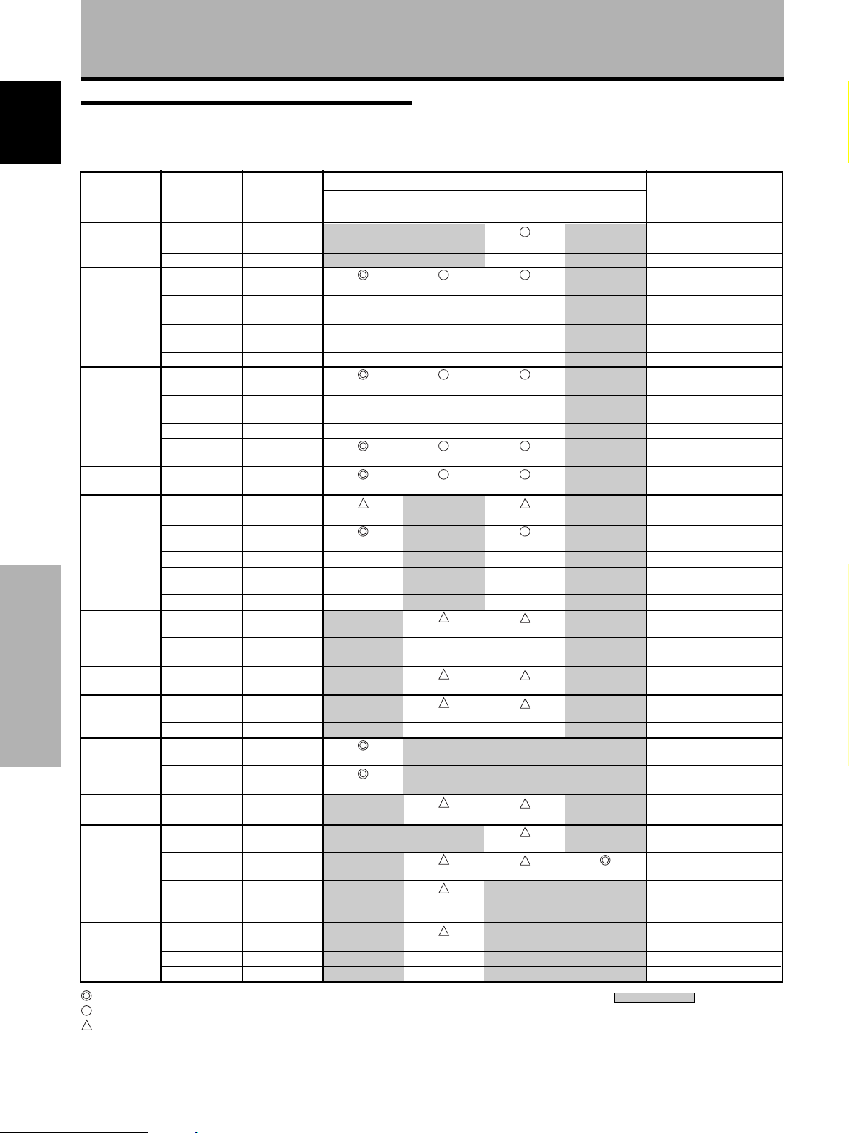
PC signal compatibilty table (INPUT3, INPUT4)
Resolution
(Dot x Line)
Vertical
frequency
Horizontal
frequency
Screen size (Dot x line)
ORIGINAL FULL ZOOM
4.3 NORMAL
Remarks
640x400
640x480
800 x600
832x624
1024x768
1152x864
1152x870
1152x900
Additional Information
1280x768
1280x960
1280x1024
1600 x 1200
: Optimal picture. Adjustment of picture position, frequency, phase etc., may be necessary.
: Picture will be enlarged but some fine detail will be hard to see.
: Simple reproduction. Fine detail will not be reproduced. Screen size will be displayed as
“~ (TYPE)”.
56.4Hz
70.1Hz
60Hz
66.7Hz
72Hz
75Hz
85Hz
56Hz
60Hz
72Hz
75Hz
85Hz
74.6Hz
43Hz
Interlace
60Hz
70Hz
75Hz
(74.9Hz)
85Hz
60Hz
72Hz
75Hz
75.1Hz
66.0Hz
76.0Hz
56Hz
60Hz
60Hz
43Hz
Interlace
60Hz
75Hz
85Hz
60Hz
65Hz
70Hz
24.8kHz
31.5kHz
31.5kHz
35.0kHz
37.9kHz
37.5kHz
43.3kHz
35.2kHz
37.9kHz
48.1kHz
46.9kHz
53.7kHz
49.7kHz
35.5kHz
48.4kHz
56.5kHz
60.0kHz
(60.2kHz)
68.7kHz
53.7kHz
64.9kHz
67.7kHz
68.7kHz
61.8kHz
71.7kHz
45.1kHz
48.4kHz
60.0kHz
46.4kHz
64.0kHz
80.0kHz
91.1kHz
75.0kHz
81.3kHz
87.5kHz
640x480
±
±
±
±
800x600
±
±
±
800x600
832x624
1024x768
1024x768
±
±
±
1280x768
1280x768
1024x768
±
±
±
±
1024x768
±
±
±
1024x720
1024x748
1024x768
±
±
1024x768
1024x768
±
1024x768
960x768
960x768
±
1024x768
±
±
1280x768
±
1280x768
±
±
±
±
1280x768
±
±
±
1280x720
1280x748
1280x768
1280x768
±
±
±
1280x768
±
±
1280x768
1280x768
±
1280x768
1280x768
1280x768
NEC PC-9800
NEC PC-9800
(852x480)
(864x480)
Apple Macintosh 13”
(1072x600)
Apple Macintosh 16”
(1376x768)
( ) indicates Apple
Macintosh 19”
Apple Macintosh 21”
Sun Microsystems LO
Sun Microsystems HI
1280x768
(1600x1024)
: Not available.
26
En
Page 31

Additional Information
Supplement 2
Signal assignment of INPUT 4 (Mini D-sub 15 pin
socket connector)
Pin No.
1
2
3
4
5
6
7
8
9
10
11
12
13
14
15
R
G
B
NC (No connection)
GND
GND
GND
GND
DDC + 5V
GND
NC (no connection)
DDC SDA
HD or H/V SYNC
VD
DDC SCL
5 1
10
6
15 1 1
Input Output
+
+
+
+
NC (No connection)
+
+
+
NC (No connection)
+
+
NC (No connection)
+
+
NC (No connection)
Explanation of Terms
Aspect ratio
The TV screen’s width to height ratio is referred to as its aspect
ratio. The aspect ratio on standard TVs is 4:3 and on wide TVs or
High Definition TVs it is 16:9.
G ON SYNC
This indicates a video signal in the form of a synchronization
signal added to the G (GREEN) signal of the R.G.B signal.
VGA
VGA is short for “Video Graphics Array”.
Generally this indicates a 640 dot x 480 line resolution.
XGA
General term for “eXtended Graphics Array”.
Generally this indicates a 1024 dot x 768 line resolution.
English
Macintosh is a registered trademark of Apple Computer, Inc.
Microsoft is a registered trademark of Microsoft Corporation.
PC-9800 is a trademark of NEC Corporation.
NEC is a trademark of NEC Corporation.
VESA is a registered trademark of Video Electronics
Standards Association.
Sun Microsystems is a registered trademarks of Sun
Microsystems, Inc.
Additional Information
27
En
Page 32

Precautions de securite
IMPORTANT
Français
Ce symbole de l'éclair, placé dans un triangle
équilatéral, a pour but d'attirer l'attention de
l'utilisateur sur la présence, à l'intérieur du coffret
de l'appareil, de "tensions dangereuses" non isolées
d'une grandeur suffisante pour représenter un risque
d'électrocution pour les êtres humains.
ATTENTION
RISQUE DE CHOC ELECTRIQUE
NE PAS OUVRIR
ATTENTION: Pour éviter tout risque d'électrocution,
ne pas enlever le couvercle (ni le panneau arrière).
Aucune pièce réparable par l'utilisateur ne se trouve
à l'intérieur. Confier tout entretien à un personnel
qualifié uniquement.
Ce point d'exclamation, placé dans un triangle
équilatéral, a pour but d'attirer l'attention de
l'utilisateur sur la présence, dans les documents
qui accompagnent l'appareil, d'explications
importantes du point de vue de l'exploitation ou de
l'entretien.
Nous vous remercions vivement d’avoir fait l’acquisition de
ce produit PIONEER.
Avant d’utiliser votre écran à plasma, veuillez lire
attentivement les “Précautions de Sécurité” ainsi que la
présente “Mode d’emploi” de manière à utiliser l’ecran à
plasma correctement.
Conservez ce manuel dans un endroit sûr. Il vous sera
sûrement utile dans les mois ou les années qui suivent.
ATTENTION: AFIN DE PREVENIR TOUS RISQUES DE
CHOC ELECTRIQUE OU DE DEBUT D’ENCENDIE, NE PAS EXPOSER CET APPAREIL A L’HUMIDITE OU A LA PLUIE.
ATTENTION: Ce produit peut seulement être utilisé
avec le socle, modèle PDK-5001. L’utilisation d’autres socles
peut entraîner une instabilité pouvant causer des blessures.
AVERTISSEMENT: EN POSITIONNANT
L’EQUIPEMENT, S’ASSURER QUE LA FICHE ET LA PRISE DE
RACCORDEMENT DE L’ALIMENTATION SONT FACILEMENT
ACCESSIBLES.
Pour garantir un rayonnement thermique adéquat, placer l’unité
à une certaine distance des autres équipements, murs, etc.
Commencer
(normalement à une distance supérieure à 10 cm). Eviter les
modes d’installation décrits ciaprès qui entraînent l’obstruction
des orifices et provoquent une accumulation de chaleur interne,
d’où un risque d’incendie.
• Ne pas essayer de placer l’unité dans des espaces réduirts et
mal ventilés
• Ne pas la placer sur un tapis
• Ne pas la recouvrir d’un tissu etc.
• Ne pas la placer sur le côté
• Ne pas la renverser
• Si une installation spéciale est envisagée, comme un montage
à proximité immédiate du mur, un placement horizontal,
consulter d’abord le revendeur Pioneer de votre région.
Remarques sur l’installation:
Ce produit est vendu en assumant qu’il sera installé par un
personnel suffisamment expérimenté et qualifié. Faites toujours
réaliser le montage et l’installation par un spécialiste ou par votre
revendeur.
PIONEER ne peut être tenu responsable pour tout dommage
causé par une erreur d’installation ou de montage, une mauvaise
utilisation ou un désastre naturel.
Remarque pour le revendeur:
Après l’installation, assurez-vous de remettre ce mode d’emploi
à l’utilisateur et de lui expliquer comme utiliser ce produit.
Les symboles qui suivent se trouvent sur les
étiquettes apposées sur le produit. Ils alertent
les utilisateurs de ce matériel ainsi que le
personnel du service aprésvente sur toutes les
situations qui présentent un danger potentiel.
DANGER
Ce symbole concerne un risque ou une
pratique dangereuse qui peut entraîner des
blessures graves ou la mort.
ATTENTION
Ce symbole concerne un risque ou une
pratique dangereuse qui peut entraîner des
blessures ou des dégâts matériels.
ii
i
Fr
Page 33

Particularités Table des matières
÷ Utilisation d’un écran large XGA à plasma, aux
performances élevées
Cet écran large XGA bénéficie de perfectionnements qui
permettent l’emploi de 2,5 fois plus de données que dans le cas
d’un écran de télévision VGA actuel*.
Avec une résolution horizontale de 1280 pixels et une définition
verticale de 768 pixels, l’écran large XGA autorise la reproduction
inégalée d’images fournies par un lecteur de DVD, un ordinateur
ou un périphérique.
* Avec une image de 4:3.
VGA: 640 pixels x 480 pixels
XGA: 1024 pixels x 768 pixels
÷ Obtention d’une luminance de niveau XGA
Grâce à l’emploi de techniques originales d’optimisation
développées par PIONEER, il est possible d’obtenir une
luminance de très haute valeur tout en conservant les valeurs de
résolution affichées.
÷ Profondeur réduite de 9,8 cm pour un écran
appartenant à la catégorie des 50 pouces
Non seulement la largeur du panneau est de 50 pouces, ce qui
pour un tube cathodique n’irait pas sans quelques problèmes, mais
encore la profondeur est très réduite puisqu’elle atteint à peine 9,8
cm, ce qui ouvre un champ de possibilités tout à fait nouveau dans
la manière de concevoir un salon d’écoute et de visualisation.
÷ Nombreuses possibilités d’installation
Conçu pour être fixé au mur, posé sur une table ou monté sur un
support, cet écran à plasma s’accommode donc de diverses
installations.
÷ Options disponibles (vendues séparément)
(Pour de plus amples détails concernant ces options,
consultez le revendeur.)
1 Table : Cette table a été spécialement étudiée
pour recevoir l’écran PDP-502MXE.
2 Suspension murale :
ATTENTION:
Cet appareil ne peut être posé que sur un support PDK-5001.
L’utilisation d’autres support peut rendre l’installation instable et
entraîner des blessures.
3 Enceintes acoustiques spécialement conçues pour les écrans à
plasma (largeur: 7,4 cm)
:
L’adoption d’une structure verticale double comprenant un
haut-parleur d’aigus à dôme de 2,5 cm, placé au centre, et des
haut-parleur elliptiques de 4,5 cm, a permis une grande
amélioration de l’orientation du champ sonore. Bien que la
profondeur de l’enceinte ne soit que de 7,4 cm, les sonorités
sont particulièrement agréables et riches. (Lorsque les
enceintes sont montées sur l’écran à plasma, le panneau de
commande devient indisponible;
enceintes sur le noyau en ferrite fourni et reliez les extrémités
à la voie droite.)
Cette suspension permet de fixer l’écran à
plasma à des murs de différentes nature
bobinez le cordon des
.
Particularités....................................... i
Avant de commencer ........................ 2
Comment utiliser ce mode d’emploi ................. 2
Vérification des accessoires fournis .................. 3
Les différents organes et leurs rôles ..
Appareil ............................................................... 4
Télécommande ................................................... 5
Panneau de raccordement ................................. 6
Installation et raccordements .......... 8
Installation de l’écran à plasma ......................... 8
Raccordement à un ordinateur personnel ...... 10
Raccordements audio ....................................... 11
Raccordement du cordon de commande d’ensemble ......
11
Raccordement du cordon d’alimentation ....... 12
Comment faire cheminer les câbles ................ 12
Mise en oeuvre de l’ensemble ....... 13
Mise en oeuvre après raccordement............... 13
Fonctionnement .............................. 14
Choix de la source ............................................ 14
Choix du format de l’image ............................. 16
ÉCONOMIE D’ÉNERGIE .................................... 17
Réglages de l’écran à plasma......... 18
Réglage de la qualité de l’image ..................... 18
Réglages des caractéristiques de l’image....... 19
Augmentation de la luminosité de l’image du
PC (ABL) ......................................................... 20
Augmentation de la luminosité de l’image PC
(H/V ENHANCE) ............................................. 21
Rétablissement des valeurs par défaut ........... 21
Informations complémentaires ..... 22
Nettoyage .......................................................... 22
Mise en place des piles de la télécommande .. 22
Utilisation de la télécommande ....................... 23
Guide de dépannage ........................................ 23
Caractéristiques techniques ............................. 25
Supplément 1 .................................................... 26
Supplément 2 .................................................... 27
Glossaire ............................................................ 27
Français
4
Particularités / Table des matières
÷ Conception visant à économiser l’énergie
Cet écran à plasma a été conçu pour consommer aussi peu
d’énergie que possible lorsqu’il se trouve en veille. En effet, dans ce
mode de fonctionnement, la consommation atteint à peine 0,6 Watt.
1
Fr
Page 34

Avant de commencer
Comment utiliser ce mode d’emploi
Ce mode d’emploi s’organise autour d’explications
classées dans l’ordre qui nous a paru le plus logique à
Français
quelqu’un qui prendrait possession de l’écran à plasma
pour la première fois.
Après avoir retiré l’écran à plasma de son emballage et
vous être assuré que toutes les accessoires sont
présents, nous vous suggérons de lire la section “Les
différents organes et leurs rôles” qui débute à la page 4
de manière à vous familiariser avec les organes et les
commandes de l’écran à plasma et de sa télécommande.
La section “Installation et connexions” qui débute à la
page 8 couvre tous les points nécessaires concernant
l’installation de l’écran à plasma et les connexions à
ordinateur personnel (PC).
Ce qui suit est un exemple de mode opératoire expliquant
comment choisir la largeur de l’image. Les illustrations
permettent de vérifier visuellement que les étapes se
déroulent bien comme il convient. Examinez cet exemple
avant de poursuivre la lecture du mode d’emploi.
1 Appuyez sur la touche MENU pour afficher la page
de menu.
2 Utilisez les touches 5/∞ pour choisir l’option
SCREEN.
MEN
U
EEN
R
RE
L
R
:
U
MENU O
:
S
R
P
EL
E
S
S
U
E
T
AV
ECT
:
H
.
POSI.
V
.
.
I
OS
P
.
V
SI
C
LK F
C
LK
R
ESET
F
Z
E
RQ
PHS
E
F
0
:
0
:
–
––
:
0
:
0
IN
A
M
P
ICT
S
C
A
L
O
P
SETU
M
EN
WE
La section “Mise en oeuvre de l’ensemble” qui débute à
là page 13 traite des réglages à réaliser à partir des
menus affichés de façon à intégrer le fonctionnement de
l’écran à plasma à celui des autres appareils de
l’installation. En fonction des raccordements réalisés, il
peut être inutile de lire cette section.
Les autres sections de ce mode d’emploi abordent des
opérations de base telle le choix d’une source et des
opérations plus détaillées telles que l’affichage d’image
correspondant aux appareils utilisés et aux goûts
personnels.
Description des modes
opératoires
Avant de commencer
Les modes opératoires sont présentés sous la forme
d’étapes numérotées. La plupart sont rédigés en tenant
compte des possibilités de la télécommande, à moins
que la touche ou la commande ne soient présentes que
sur l’écran à plasma. A noter qu’une touche ou une
commande de l’écran à plasma ayant le même nom
qu’une touche ou une commande de la télécommande,
jouent les mêmes rôles.
3 Appuyez sur la touche 3.
IN
A
M
P
ICT
S
C
AL
O
P
SETU
M
EN
WE
U
MEN
U
E
R
N
REE
S
L
RE
S
R
P
:
U
MENU O
::
S
EL
E
T
AV
ECT
H
.
POSI.
V
.
OS
P
.
V
SI
E
C
LK F
C
LK
R
ESE
F
F
S
ET
:
:
.
I
:
Z
E
:
RQ
:
PHS
T
ADJ UST
–––
0
0
0
0
4 Utilisez les touches 5/∞ pour choisir l’option
V. POSI.
MEN
U
REE
L
RE
R
:
U
MENU O
:
S
R
N
P
EL
E
S
S
U
H
V
E
T
V
AV
E
C
C
R
F
F
SETADJ UST
ECT
.
POSI.
.
OS
P
.
SI
LK F
LK
ESET
:
I
Z
E
RQ
PHS
:
0
:
.
0
:
–
––
:
0
:
0
IN
A
M
P
ICT
S
C
AL
O
P
SETU
M
EN
WE
5 Appuyez sur la touche SET pour afficher les
valeurs possibles pour le paramètre choisi.
REE
C
S
N
V
.P
O
S
ITION
0
S
:EXIT:ADJUST
ET
6 Utilisez les touches 5/∞ pour choisir la valeur
désirée.
2
Fr
Page 35

Vérification des accessoires
fournis
Avant de commencer
6 2 supports pour l’écran
Assurez-vous que les accessoires suivants font partie de
la fourniture.
1 Boîtier de télécommande
STANDBY
/ON
SCREEN
VIDEO
SIZE
RGB 1 RGB 2
MUTE
Y/C
VOL
MENU
DISP
SET
CU-V154
Î
2 2 piles AA (R6)
3 Chiffon de nettoyage (pour essuyer l’écran)
4 2 colliers rapides
Français
7 2 rondelles (large)
8 2 rondelles (petite)
9 2 boulons six pans creux
0 Boîte pour télécommande
Utilisez cette boîte
pour y ranger la
télécommande. Si vous
fixez cette boîte à
l’arrière de l’écran,
veillez à ce qu’elle
n’obstrue pas les ouïes
d’aération.
5 2 serre-cable
- Noyau en ferrite
÷ Mode d’emploi
Avant de commencer
Utilisez le noyau lors de la
liaison aux enceintes. Le
câble de liaison de la voie
droite doit être bobiné sur
le noyau de ferrite. (Pour
de plus amples détails
concernant le bobinage,
reportez-vous à la page
11.)
3
Fr
Page 36

Les différents organes et leurs rôles
Appareil
Panneau de commande de l’écran à plasma
Français
Appareil
STANDBY/ON
INPUT
MENU
ADJUST
SET
SIZE
DISPLAY
3
4
5
6
7
8
9
0
1
Appareil
1 Support pour l’écran
2 Capteur de télécommande
Dirigez le faisceau de télécommande vers ce capteur
(page 23).
Les différents organes et leurs rôles
Panneau de commande de l’écran à plasma
3 Témoin STANDBY/ON
Lorsque l’écran à plasma est en veille, ce témoin est
de couleur rouge; il s’éclaire de couleur vert quand
l’écran à plasma est en fonctionnement (page 14).
4 Touche STANDBY/ON
Appuyez sur cette touche pour mettre l’écran en
service ou en veille (page 14).
5 Touche INPUT
Appuyez sur cette touche pour choisir le signal
d’entrée (page 14).
2
Remarque
Lorsque les enceintes sont montées sur l’écran
à plasma, le panneau de commande devient
indisponible.
6 Touche MENU
Appuyez sur cette touche pour ouvrir ou fermer les
menus s’affichant sur l’écran (pages 13 à 21).
7 Touche ADJUST (5/∞/3/2)
Utilisez ces touches pour naviguer dans les menus et
choisir des valeurs de réglage.
L’utilisation des touches du curseur pour les
procédures est clairement indiquée en bas de
l’affichage sur l’écran (pages 13 à 21).
8 Touche SET
Appuyez sur cette touche pour définir une valeur ou
valider un choix (pages 13 à 21).
9 Touche SIZE
Appuyez sur cette touche pour choisir manuellement
le format de l’image (page 16).
0 Touche DISPLAY
Appuyez sur cette touche pour afficher le nom de
l’entrée et de mode de fonctionnement actuels
(page 15).
4
Fr
Page 37

Télécommande
1
2
3
STANDBY
SCREEN
/ON
SIZE
INPUT
VIDEO
Y/C VOL
12
RGB
RGB
(D-sub)
(BNC)
34
MENU
MUTING
DISPLAY
Les différents organes et leurs rôles
6
Français
7
8
9
4
5
1 Touche STANDBY/ON
Appuyez sur cette touche pour mettre l’écran en
service ou en veille (page 14).
2 Touches INPUT
Utilisez ces touches pour choisir le signal d’entrée
(page 14).
3 Touche MENU
Appuyez sur cette touche pour ouvrir ou fermer les
menus s’affichant sur l’écran (pages 13 à 21).
SET
Î
6 Touche SCREEN SIZE
Appuyez sur cette touche pour choisir manuellement
le format de l’image (page 16).
7 Touche MUTING
Appuyez sur cette touche pour couper les sons (page
15).
Les différents organes et leurs rôles
8 Touches VOL (+/–)
Utilisez ces touches pour régler le niveau d’écoute
(page 15).
4 Touches ADJUST (5/∞/3/2)
Utilisez ces touches pour naviguer dans les menus et
choisir des valeurs de réglage.
L’usage de ces touches est clairement indiqué sur les
pages de menu affichées sur l’écran (pages 13 à 21).
5 Touche SET
Appuyez sur cette touche pour définir une valeur ou
valider un choix (pages 13 à 21).
9 Touche DISPLAY
Appuyez sur cette touche pour afficher le nom de
l’entrée et de mode de fonctionnement actuels (page
15).
5
Fr
Page 38

Les différents organes et leurs rôles
Panneau de raccordement
Pour de plus amples détails concernant les raccordements, reportez-vous aux pages indiquées entre parenthèses.
Français
1 2 3 4 5 6 7 8
+–
SPEAKER
R
8 Ω – 16 Ω
AUDIO OUTPUT
COMBINATION
1 Borne SPEAKER (R)
Pour le raccordement à l’enceinte droite. Cette
enceinte doit présenter une impédance comprise
entre 8 et 16 Ohms (page 11).
2 AUDIO OUTPUT (Mini-prise stéréo)
Utilisez cette sortie pour appliquer à un amplificateur
audiovisuel ou un appareil similaire, les sons
provenant de l’appareil source qui est relié à cet écran
à plasma (page 11).
3 COMBINATION IN/OUT
Ne branchez aucun appareil sur ces prises.
Les différents organes et leurs rôles
Ces prises sont utilisées pour effectuer des réglages
en usine.
4 CONTROL IN/OUT
Utilisez ces prises pour le raccordement de l’écran à
plasma à d’autres appareils PIONEER portant la
marque Î . Cela fait, cet écran peut être considéré,
du point de vue des commandes, comme faisant
partie de l’ensemble (page 11).
5 RS-232C
Ne branchez aucun appareil sur cette prise.
Cette prise est utilisée pour effectuer des réglages en
usine.
IN
OUT
IN
OUT
CONTROL
RS-232C
(INPUT 4)
R – L
(INPUT 3)
AUDIO INPUT
ANALOG
R G B
INPUT4
OUTPUT
ANALOG
(
R G B
(
6 AUDIO INPUT (Mini-prise stéréo)
Utilisez cette prise pour disposer des sons appliqués
sur INPUT4.
Connectez la prise de sortie audio de l’appareil
connecté à INPUT 4 à cette prise (page 11).
7 AUDIO INPUT (Prises Cinch)
Utilisez ces prises pour disposer des sons appliqués
sur INPUT3.
Connectez les prises de sortie audio de l’appareil
connecté à INPUT 3 à ces prises (page 11).
Remarque: La voie gauche (L) n’est pas prévue pour
les sources monophoniques.
8 INPUT4
Utilisez ces prises pour le branchement d’un
ordinateur personnel (PC). Choisissez la prise en
fonction de la nature du signal fourni par l’appareil
connecté. Utilisez la prise INPUT4 OUTPUT pour
appliquer le signal RGB sur un monite ur extérieur ou
un autre appareil (page 10).
Remarque: Le signal RGB n’est pas présent sur la
prise INPUT4 OUTPUT lorsque l’écran à plasma est
hors tension ou en veille.
6
Fr
Page 39

Les différents organes et leurs rôles
9 0 - = ~
Français
G B R
[ON SYNC] [H/V SYNC]
INPUT3
HD VD
75Ωj2.2kΩ
9 INPUT3
Pour la connexion à un ordinateur personnel (page 10).
0 Sélecteur d’impédance du signal de synchronisation
En fonction des connexions faites à INPUT 3, il peut
être nécessaire de régler ce commutateur de façon à
s’adapter à l’impédance de sortie du signal de
synchronisation de l’ordinateur personnel.
Quand l’impédance de sortie du signal de
synchronisation de l’ordinateur personnel est
supérieure à 75 Ω, réglez ce commutateur sur la
position 2,2 kΩ (page 10).
- Interrupteur MAIN POWER
Utilisez cet interrupteur pour mettre l’écran à plasma
sous tension ou hors tension.
MAIN POWER
OFF ON
AC INLET
SPEAKER
8 Ω – 16 Ω
+–
L
Les différents organes et leurs rôles
= AC INLET
Utilisez cette prise pour connecter un cordon
d’alimentation à une prise secteur (page 12).
~ Borne SPEAKER (L)
Pour le raccordement à l’enceinte gauche. Cette
enceinte doit présenter une impédance comprise
entre 8 et 16 Ohms (page 11).
7
Fr
Page 40

Installation et raccordements
Installation de l’écran à plasma
Installation de l’écran à plasma sur les supports
fournis
Français
Fixez les supports sur la surface d’installation.
Utilisez des boulons M8 disponibles dans le commerce,
dont la longueur est supérieure de 25 mm à l’épaisseur
de la surface d’installation.
1
Au moyen de boulons M8 disponibles dans le commerce,
assurez la fixation des supports fournis à la surface
d’installation préalablement percées de 4 trous convenables.
Avant
798 mm
4 Posez l’écran à plasma dans les supports.
5 Assurez la fixation de l’écran à plasma au moyen
de la rondelle et du boulon fournis.
110 mm
2
Engagez une rondelle (large) fournie dans un support.
Installation et raccordements
3
Au moyen d’un tournevis ou d’une pièce de monnaie, retirez
les caches
A
et A’de l’écran à plasma.
Arrière
Pour serrer, utilisez une
clé hexagonale de 6 mm.
ATTENTION
Compte tenu de son poids 40 kg et de sa profondeur réduite,
l’écran à plasma est peu stable; nous conseillons que le
déballage et l’installation soient effectués par 2 personnes.
AA'
8
Fr
Page 41

Installation et raccordements
Installation à l’aide du support ou de la fixation
PIONEER en option
÷ Que ce soit à l’aide du support ou de la fixation, l’installation
de l’écran à plasma doit être réalisée par un technicien
compétent ou par le revendeur.
÷ Lors de l’installation, utilisez les boulons fournis avec le
support ou la fixation.
÷ Pour de plus amples détails concernant l’installation, reportez-
vous aux instructions qui accompagnent le support ou la
fixation.
Installation à l’aide d’accessoires autres que le
support ou la fixation PIONEER (vendus
séparément)
÷ Dans toute la mesure du possible, utilisez des pièces et des
accessoires fabriqués par PIONEER. PIONEER ne pourra être
tenue responsable des accidents et dommages qui
résulteraient de l’utilisation de pièces ou d’accessoires
fabriqués par des tiers.
÷ Pour effectuer une installation personnalisée, consultez le
revendeur ou un technicien compétent.
Ouïes d’aération (ventilateur)
Perçage b
Perçage b
Accrochage de l’écran à plasma à un mur
L’écran à plasma possède des perçages destinés à
permettre sa fixation sur un mur, etc. Les perçages qui
peuvent être utilisés sont indiqués sur le schéma cidessous. (Les rivets peuvent être retirés au moyen d’un
tournevis ou d’une pièce de monnaie.)
÷ L’écran à plasma doit être maintenu en 4 points
(minimum) placés au-dessus et au-dessous de l’axe
horizontal, et à droite et à gauche de l’axe vertical.
÷ Dans le cas des perçages a et b, utilisez des boulons
dont la longueur est telle qu’ils pénètrent dans l’écran à
plasma de 12 mm au moins et de 20 mm au plus.
Reportez-vous à la vue de côté ci-dessous.
÷ L’écran à plasma est muni d’une vitre qui interdit sa
pose sur une surface qui n’est pas plane.
FrançaisInstallation et raccordements
Perçage b
Perçage a
Axe
Vue arrière
ATTENTION
Pour éviter toute anomalie de fonctionnement, une surchauffe de
l’écran à plasma et un incendie, veillez, en fin d’installation, à ce
que les ouïes d’aération ne soient pas obstruées. Par ailleurs, de
l’air chaud étant évacué par les ouïes d’aération, l’accumulation
de poussières sur la surface d’installation et sa détérioration
progressive sont à considérer.
ATTENTION
Assurez-vous d’utiliser un boulon M8 (pas = 1,25 mm). (Seule
cette taille de boulon peut être utilise’e.)
Perçage bPerçage b
Surface de pose
Appareil
Axe
Perçage a
Perçage b
Boulon
Perçage b
12 à 20 mm
Vue de côté
ATTENTION
Compte tenu de son poids 40 kg et de sa profondeur réduite,
l’écran à plasma est peu stable; nous conseillons que le
déballage et l’installation soient effectués par 2 personnes.
ATTENTION
L’épaisseur de cet écran à plasma est très réduite. Veillez à ce
qu’il ne puisse pas se renverser s’il est soumis à des vibrations.
Fixation,
etc.
Perçage a
Boulon
12 à 20 mm
9
Fr
Page 42

Raccordement à un ordinateur
personnel
La méthode de raccordement dépend du type de
Français
l’ordinateur. Avant d’effectuer les raccordements, veuillez
lire attentivement le mode d’emploi de l’ordinateur.
Avant tout raccordement veillez à ce que l’écran à plasma
et l’ordinateur soient tous deux hors tension.
Pour les signaux d’entrée PC et les tailles d’écran avec
lesquelles cet appareil est compatible, reportez-vous au
supplément 1 (page 26).
Raccordement d’une source analogique RVB
avec signaux de synchronisation séparés
Utilisez cette possibilité si la source RVB peut fournir 5
signaux séparés: vert, bleu, rouge, synchronisation
horizontale et synchronisation verticale.
Pour le raccordement à INPUT3
Installation et raccordements
Pour le raccordement à INPUT4
ANALOG
R G B
INPUT4
Branchez le câble entre la prise d’entrée de l’écran à
plasma et la prise de sortie de l’ordinateur personnel.
Serrez soigneusement les vis des connecteurs à chaque
extrémité du câble.
Un réglage général à l’aide des menus affichés sur l’écran
est nécessaire après raccordement. Reportez-vous à la
page 13.
ANALOG
(
OUTPUT
R G B
(
G B R HD VD
INPUT3(ON SYNC) (H/V SYNC)
75Ω j 2.2kΩ
Installation et raccordements
Si vous utilisez la prise INPUT3, placez le sélecteur
d’impédance de manière à adapter l’appareil à
l’impédance de sortie du signal de synchronisation.
Si l’impédance de sortie du signal de synchronisation est
supérieure à 75 Ohms, placez ce sélecteur sur la position
2,2 kOhms.
Un réglage général à l’aide des menus affichés sur l’écran
est nécessaire après raccordement. Reportez-vous à la
page 13.
Remarque
Selon le type de l’ordinateur, un adaptateur (fourni avec
l’ordinateur ou vendu séparément) peut être nécessaire pour
effectuer le raccordement ci-dessus.
Veuillez consulter le mode d’emploi de l’ordinateur ou le
revendeur.
Pour le raccordement à INPUT4
ANALOG
R G B
INPUT4
OUTPUT
ANALOG
(
R G B
(
Vers un moniteur extérieur.
Cet écran à plasma est prévu pour que le signal RGB
puisse être appliqu à un moniteur ou un autre appareil à
partir de la prise INPUT4 OUTPUT.
10
Fr
Remarque
Le signal RGB n’est pas présent sur la prise INPUT4 OUTPUT
lorsque l’écran à plasma est hors tension ou en veille.
Page 43

Installation et raccordements
CONTROL
IN
OUT
CONTROL
IN
OUT
CONTROL
IN
OUT
CONTROL
IN OUT
Raccordements audio
Avant tout raccordement veillez à ce que les appareils
soient tous deux hors tension.
Raccordement des enceintes
Cet écran à plasma est doté de prises de sortie pour
enceintes acoustiques (non fournies) qui ont été
spécialement conçues pour fonctionner avec l’écran.
Avant d’effectuer un raccordement, reportez-vous aux
illustrations.
Torsadez les
brins mis à nu.
10 mm
Soulevez la languette
puis introduisez le
conducteur. Abaissez la
languette pour
maintenir le conducteur
en place.
Remarque
Veillez à ne pas inverser les polarités (+) et (–) soit au niveau des
enceintes, soit au niveau de l’écran à plasma. Si les polarités sont
inversées, les sons manquent de naturel et de puissance dans
les graves. Bobinez le cable d’enceinte sur le noyau de ferrite
fourni et reliez les extrémités à la voie droite (placez le noyau de
ferrite aussi près que possible de la prise de sortie pour
l’enceinte de la voie droite).
Raccordement du cordon de
commande d’ensemble
Après avoir relié le cordon de commande d’ensemble, à
d’autres appareils PIONEER portant la marque Î, le
fonctionnement de ces appareils peut être commandé à
distance à partir du boîtier de télécommande fourni.
Quand la connexion est faite à la prise CONTROL IN sur
un autre appareil, le capteur de télécommande de cet
appareil ne reçoit plus les signaux. Vous devez donc
diriger le boîtier de télécommande vers le capteur de
télécommande de l’écran à plasma.
Remarques
÷ Avant tout raccordement veillez à ce que les appareils
soient hors tension.
÷ Effectuez tous les raccordements ordinaires puis les
raccordements du cordon de commande d’ensemble.
Appareil
FrançaisInstallation et raccordements
Aussi court que possible
Vers l’enceinte de la voie droite
Raccordements aux entrées audio de cet écran à
plasma
Cet écran à plasma est doté de deux entrées audio et
d’une sortie audio. Le tableau qui suit donne pour chaque
entrée les entrées audio correspondantes.
Entrée
vidéo
INPUT3
INPUT4
Prises d’entrée
audio
Cinch
(G/D)
Mini-fiche stéréo
(G/D)
Les sons provenant de l’entrée
choisie sont présents sur
÷ bornes SPEAKER
÷ les mini-prises stéréo (G/D)
Sortie son
Les cordons de
commande (non fournis)
sont prévus pour des
signaux monophoniques,
et sont munis de minifiches (sans résistance).
11
Fr
Page 44

Installation et raccordements
Raccordement du cordon
d’alimentation
Connectez le cordon d’alimentation après que la
Français
connexion de tous les appareils est terminée.
Caractéristique du cordon d’alimentation du PDP-502MXE
Cordon ........................... Aire transversale 3 x 1,0 mm
(Conformément à CEE 13)
Connecteur ................................................. 10 A, 250 V
(Conformément à EN60320, feuille C13)
Fiche ....................... À usage international (10 A, 250 V)
Exemple:
R.U. : Fiche UK 13 A avec un fusible de 13 A
(Conformément à BS1363)
Europe : 10A/16A 250V (Conformément à CEE
7,1 V)
ATTENTION
÷ Alimentez l’écran à plasma à partir de la tension prescrite
(100 - 240 Volts CA, 50/60 Hz); tout autre tension peut
provoquer un incendie ou une secousse électrique.
÷ L’écran à plasma doit être alimenté par un cordon à deux
conducteurs plus un conducteur de masse. Veillez à ce que la
prise possède une broche de mise à la terre et qu’elle soit
convenablement câblée. En cas d’utilisation d’un adaptateur, le
conducteur de masse doit tout de même être relié à la terre.
1 Groupez les câbles en utilisant les colliers rapides
fournis.
Introduisez la partie 1 dans un des perçages à
l’arrière de l’écran à plas ma puis insérez 2 à l’arrière
de 1 pour assurer la fixation.
Les colliers rapides sont conçus pour que l’ouverture
soit difficile. Fermez-les soigneusement.
2
Fixation des colliers rapides à l’écran à plasma
Engagez les colliers rapides dans les trous 4 repérés par
÷ sur l’illustration ci-dessous.
Pour retirer les colliers rapides
A l’aide d’une pince, tordez le collier de 90° puis tirez-le
vers vous. Avec le temps, le collier peut se détériorer et il
peut être nécessaire de la remplacer après que vous
l’avez retiré.
Comment faire cheminer les câbles
Des colliers rapides et des serre-câble sont fournis pour
lier les câbles en tre eux. Après raccordements des
appareils, procédez aux opérations qui suivent.
Installation et raccordements
1
1
2 Liez les câbles et assurez leur maintien au moyen
des serre-câble fournis.
Remarque
Les câbles peuvent cheminer d’un côté ou de l’autre.
* Vue de l’arrière de l’écran.
2
2
12
Fr
Page 45

Mise en oeuvre de l’ensemble
Mise en oeuvre pour G ON SYNC (CLAMP)
Mise en oeuvre après raccordement
En principe, la source RVB fournit 5 signaux séparés: vert,
Après le raccordement des appareils aux prises INPUT3 ou INPUT4, des
réglages à l’aide des menus affichés sur l’écran sont nécessaires.
Procédez aux opérations décrites ci-dessous et effectuez les réglages
en fonction des appareils connectés.
1
Mettez l’écran à plasma sous tension au moyen de l’interrupteur
MAIN POWER que porte le panneau de commande.
Le témoin STANDBY/ON s’éclaire de couleur rouge.
bleu, rouge, synchronisation horizontale et synchronisation
verticale. Si le raccordement est effectué au moyen de la
prise G ON SYNC, 3 signaux seulement sont disponibles:
rouge, vers (synchronisations horizontale et verticale) et bleu.
Si l’ordinateur personnel utilisé est un modèle avec une
connexion G ON SYNC, le réglage sur écran est
nécessaire.
2 Appuyez sur la touche STANDBY/ON pour
mettre l’écran à plasma en service.
Le témoin STANDBY/ON s’éclaire de couleur verte.
3 Choisissez INPUT3 ou INPUT4.
4
Appuyez sur la touche MENU pour afficher la page de menu.
La page de menu s’affiche.
5 Utilisez les touches 5/∞ pour choisir l’option SET
UP puis appuyez sur la touche SET.
IN
A
M
P
ICT
S
C
REE
ALLRE
O
WE
P
SETU
U
M
EN
6
Utilisez les touches
TU
E
S
T
ERM
S
E
TTI
G
SI
L
AM
C
ABL
H.ENHANCE
ENHANCEV.
EX I T
:
S
U
MEN
U
E
R
N
S
E
T
S
AV
R
:
MENU O
:
P
I
N
AL
P:M
EL
P
S
EL
N
N
ECT
E
F
F
S
ECT
5/∞
pour choisir l’option SETTING.
C
L
:BN
A
G
:PC
:
R
B
G
O
DE
F
OF
:
:
:
S
ET
ET
0
0
:
X
N
E
T
1
:
C
A
E
H
NG
7 Appuyez sur SET pour choisir “PC”.
En fonction du signal d’entrée, cet appareil peut ne
pas être capable de réaliser le réglage correct.
Assurez-vous que ce réglage est sur “PC”.
Remarque
Les opérations 6 à 7 sont nécessaires lorsque le signal d’entrée a une
fréquence de 31,5 kHz (horizontalement) et de 60 Hz (verticalement).
Lors de l’entrée d’un signal de fréquence de 48,4 kHz
(horizontalement) et de 60 Hz (verticalement), “1024 x 768” ou
“1280 x 768” doit être réglé sur les réglages “PC” en fonction
du signal d’entrée.
Pour les signaux à d’autres fréquences, les réglages sont effectués
automati quement et ne peuvent donc pas être modifiés.
8
Appuyez sur la touche MENU pour abandonner la page de
menu lorsque la mise en oeuvre est terminée.
Remarques
÷
Effectuez cette mise en oeuvre pour chaque entrée (INPUT3 ou INPUT4).
÷ Veuillez vous référer à “G ON SYNC (CLAMP)” sur cette page
pour plus d’informations sur le réglage G ON SYNC.
Mise en oeuvre de G ON SYNC (CLAMP)
1
Appuyez sur la touche MENU pour afficher la page de menu.
La page de menu s’affiche.
2 Utilisez les touches 5/∞ pour choisir l’option SET
UP puis appuyez sur la touche SET.
MEN
U
R
N
R
P
:
MENU O
:
S
EL
P
I
N
N
TTI
N
AL
P
L
ENHAN
ENHAN
I
T
S
ECT
EL
E
S
S
A
G
U
E
T
AV
ECT
L
CE
CE
E
F
:BN
:PC
:
R
:M
:
O
:
:
F
S
G
O
S
F
ET
C
B
DE1
F
0
0
ET
:
X
N
E
T
:
C
A
E
H
NG
IN
A
M
P
ICT
S
C
REE
ALLRE
O
WE
P
SETU
U
M
EN
3
Utilisez les touches 5/∞ pour choisir l’option CLAMP.
TU
E
S
T
ERM
S
E
G
SI
L
AM
C
B
A
.
H
.
V
EX
:
4 Appuyez sur la touche SET pour choisir MODE2.
Chaque pression sur la touche SET, modifie comme
suit le mode choisi.
3 MODE1 (Raccordement normal)
MODE2 (Raccordement G ON SYNC) 2
5 Appuyez sur la touche MENU pour abandonner la
page de menu lorsque la mise en oeuvre est
terminée.
Remarques
÷ Effectuez cette mise en oeuvre pour chaque entrée (INPUT3
ou INPUT4).
÷ Lors de l’utilisation de cette installation, assurez vous de
vérifier attentivement la sortie du signal de l’ordinateur
personnel que vous utilisez. Pour plus d’informations, référezvous au manuel d’instruction fourni avec l’ordinateur personnel
connecté.
÷ Si l’écran devient lumineux et prend une couleur verdâtre,
choisissez la valeur MODE2 pour CLAMP.
÷ Certains ordinateurs Macintosh sont prévus pour un
raccordement de type G ON SYNC.
13
Fr
Mise en oeuvre de l’ensemble Français
Page 46

Fonctionnement
Choix de la source
Cette section explique le fonctionnement de base. Nous
abordons, dans les pages qui suivent, la manière de
Français
mettre sous tension, ou hors tension, l’écran à plasma, de
le mettre en service ou en veille, et de choisir un appareil
parmi ceux qui sont connectés.
Remarque:
INPUT1 et INPUT2 sur la télécommande peuvent être
seulement utilisés quand le boîtier vidéo optionnel, PDA-5001,
est connecté à cet appareil.
3 Appuyez sur la touche INPUT appropriée sur la
télécommande ou sur INPUT sur l’appareil
principal pour choisir l’entrée.
Sur l’appareil principal, l’entrée change chaque fois
que INPUT est pressé.
3 INPUT3
INPUT4 2
÷ L’entrée ne peut pas être modifiée quand un menu
est affiché.
÷ Si le signal fourni par l’ordinateur n’est pas
compatible avec cet écran à plasma, la mention
“OUT OF RANGE” apparaît sur l’écran.
Avant tout, assurez-vous que:
÷ Effectuez les raccordements entre l’écran à plasma et
l’ordinateur personn el conformément aux instructions
de la section “Installation et raccordements” qui
débute à la page 8.
÷ Les réglages de mise en oeuvre ont été réalisés, pour
les appareils connectés à INPUT3 et INPUT4,
conformément à la section “Mise en oeuvre de
l’ensemble”, page 13.
STANDBY/ON
2,5
INPUT
MENU
ADJUST
Fonctionnement
SET
SIZE
3
2,5
STANDBY
SCREEN
/ON
SIZE
INPUT
VIDEO
Y/C
12
RGB
3
RGB
(D-sub)
(BNC)
34
MENU
SET
MUTING
VOL
DISPLAY
4 Utilisez les touches VOLUME +/– de la
télécommande pour régler le niveau d’écoute.
Si aucune signal sonore n’est appliqué à l’écran à
plasma, cette opération est inutile.
5 Lorsque vous avez fini de regarder les images,
appuyez sur la touche
placer l’écran à plasma en veille.
Le témoin STANDBY/ON clignote puis demeure
éclairé (rouge) indiquant ainsi que l’écran est en veille.
Les commandes ne sont pas reçues quand le témoin
clignote (rouge).
STANDBY/ON pour
6 Mettez l’écran à plasma hors tension au moyen de
l’interrupteur MAIN POWER que porte le panneau
de commande.
4
Précaution
Ne laissez pas la même image affichée sur l’écran pendant une
longue période. Cela peut causer une détérioration de l’écran (on
parle de “brûlage” de l’écran) qui se traduit par la persistence de
cette image atténuée.
DISPLAY
Panneau de commande
de l’écran à plasma
Boîtier de
télécommande
1 Mettez l’écran à plasma sous tension au moyen de
l’interrupteur MAIN POWER que porte le panneau
de commande.
Le témoin STANDBY/ON s’éclaire de couleur rouge.
2 Appuyez sur la touche STANDBY/ON pour
mettre l’écran à plasma en service.
Le témoin STANDBY/ON s’éclaire de couleur verte.
14
Fr
Page 47

Fonctionnement
Pour régler le niveau d’écoute
STANDBY
SCREEN
INPUT
MENU
SIZE
Y/C VOL
RGB
(D-sub)
SET
MUTING
VOL +/–
DISPLAY
/ON
VIDEO
12
RGB
(BNC)
34
Utilisez les touches VOL + ou VOL – pour régler
le niveau de sortie des enceintes connectées.
Pour vérifier les réglages
STANDBY/ON
INPUT
MENU
ADJUST
SET
SIZE
DISPLAY
DISPLAY
STANDBY
SCREEN
/ON
INPUT
VIDEO
12
RGB
(D-sub)
(BNC)
34
MENU
F
H:
F
V:
SIZE
Y/C
RGB
SET
4
6
8
.
0
.0H
MUTING
VOL
DISPLAY
U
4
K
T4INP
H
Français
DISPLAY
Z
Z
Pour couper les sons
STANDBY
SCREEN
INPUT
(D-sub)
MENU
SIZE
Y/C
RGB
SET
MUTING
VOL
DISPLAY
MUTING
/ON
VIDEO
12
RGB
(BNC)
34
Appuyez sur la touche MUTING de la
télécommande.
Appuyez une nouvelle fois sur la touche MUTING pour
rétablir les sons.
Le son est rétabli automatiquement au bout de 8 minutes
si aucune opération n’est réalisée pendant cette période,
et le volume est ajusté sur le niveau minimum.
Utilisez les touches VOL + ou VOL – pour régler le niveau
d’écoute.
F
ULL
Appuyez sur la touche DISPLAY
Le nom de l’entrée choisie, le format de l’image et les
fréquences horizontale et verticale de balayage s’affichent
pendant environ 3 secondes.
Remarque
Les valeurs affichées pour les fréquences horizontale et verticale
de balayage ne sont qu’approximatives et peuvent être
légèrement différentes des valeurs réelles.
Fonctionnement
15
Fr
Page 48

Fonctionnement
Choix du format de l’image
Changement de la position de
l’image
Choix d’un format d’image
L’image affichée sur l’écran peut avoir un des 4 formats
Français
mentionnés dans le tableau ci-dessous.
Appuyez sur la touche SCREEN SIZE pour
choisir le format.
Chaque pression sur la touche SCREEN SIZE de la
télécommande, ou la touche SIZE de l’écran à plasma,
modifie comme suit le format.
Dans le cas des signaux provenant d’un PC
3 ORIGINAL 3 4:3 NORMAL
FULL 2ZOOM 2
(Dans le cas où le signal vidéo provient d’un ordinateur
(PC), reportez-vous au supplément 1, page 26.)
1 ORIGINAL
Le signal d’entrée et l’image sont dans un rapport point à
ligne de 1/1 et sont donc tout à fait fidèles à la source.
Pendant l’entrée de l’ordinateur personnel (1280 x 1024/
60Hz seulement), quand le réglage ZOOM est choisi, la
position de l’écran peut être ajustée avec 5/∞.
3 FULL
L’image a le format 16/9 et remplit l’écran.
A
Fonctionnement
640 points
1280 points
(L’illustration concerne une entrée 640 x 480.)
2 4:3 NORMAL
L’image remplit l’écran autant que possible mais le format
n’est pas modifi.
A
480 lignes
768 lignes
A
4 ZOOM
Le format ZOOM n’est possible que si le signal d’entrée
provient de l’ordinateur (1280 x 1024/60 Hz uniquement).
Le signal d’entrée et l’image sont dans un rapport point à
ligne de 1/1. L’image est tout à fait fidèle à la source.
Toutefois, pour que le rapport 1/1 soit maintenu une partie
de l’image n’est pas affichée.
768 lignes
1024 lignes
Utilisez les touches 5/∞ pour positionner l’image sur
l’écran.
16
Fr
Page 49

Fonctionnement
ÉCONOMIE D’ÉNERGIE
Grâce à la fonction POWER SAVE, l’écran à plasma peut
être automatiquement placé en veille quand aucun signal
vidéo ni aucun signal d’ordinateur n’est détecté. (Une
indication s’affiche sur l’écran avant le passage en veille.)
1 Appuyez sur la touche MENU pour afficher la page
de menu.
2 Utilisez les touches 5/∞ pour choisir l’option
POWER SAVE puis appuyez sur la touche SET.
MEN
U
REE
R
:
U
MENU O
:
S
RSA
O
R
N
P
EL
:
:
U
E
S
E
S
AV
ECT
VE
MOD
MOD
T
E
F
F
:
X
N
E
T
E1
E
S
ET
2
IN
A
M
P
ICT
S
C
ALLRE
O
WE
P
SETU
M
EN
3 Appuyez sur 5/∞ pour choisir “PC”.
WE
O
P
V
IDE
P
C
5 Appuyez sur la touche MENU pour abandonner la
page de menu dès que les réglages sont terminés.
Remarque
Le réglage POWER SAVE est commun pour INPUT3 et INPUT4.
Pour replacer l’écran à plasma en
fonctionnement
Appuyez sur la touche STANDBY/ON de l’écran ou
de la télécommande.
Si “MODE 2” est choisi pour l’entrée PC, reprendre une
opération sur le PC ou appuyer sur la touche INPUT sur
l’appareil principal ou la télécommande, peut aussi
remettre l’appareil en service.
Français
T
E
XI
:
S
ECT
EL
:
S
C
A
E
H
ET
NG
4 Appuyez sur la touche SET pour choisir le mode
d’économie d’énergie.
Le mode PC POWER SAVE change chaque fois que
SET est pressé comme suit:
3 OFF
MODE2 2 MODE1 2
÷ Avec “OFF”, l’écran à plasma demeure en
fonctionnement qu’un signal de synchronisation soit
présent à l’entrée ou non.
÷ Avec “MODE1”, l’écran à plasma passe
automatiquement en veille si aucun nouveau signal
de synchronisation n’est appliqué à l’entrée pendant
8 minutes.
÷ Quand “MODE 2” est choisi, cet appareil est mis
en mode de veille et d’économie d’énergie si aucun
signal de synchronisation n’est entré. Cependant, si
un signal de synchronisation est entré à nouveau,
cet appareil est remis en service.
Fonctionnement
17
Fr
Page 50

Réglages de l’écran à plasma
Réglage de la qualité de l’image
1 Appuyez sur la touche MENU pour afficher la page
Français
de menu.
2 Utilisez les touches 5/∞ pour choisir l’option
PICTURE puis appuyez sur la touche 3.
A
IN
M
P
ICT
S
C
REE
ALLRE
O
WE
P
SETU
U
M
EN
U
MEN
U
E
R
N
S
E
S
AV
R
P
:
MENU O
:
S
ECT
EL
C
ON
T
B
RI
G
R
L
T
E
E
G
L
E
B
L
E
R
ESET
F
F
S
:ADJUS
ET
:
R
ST
A
:
H
T
:
V
L
E
:
V
L
E
:
V
L
E
T
3 Utilisez les touches 5/∞ pour choisir le paramètre
à régler puis appuyez sur la touche SET.
A
IN
M
P
ICT
S
C
REE
ALLRE
O
WE
P
SETU
U
M
EN
U
MEN
U
E
R
N
S
E
S
AV
R
P
:
MENU O
:
S
ECT
EL
:
C
ON
R
ST
A
T
B
RI
H
T
G
R
L
V
L
E
F
G
B
R
ESET
F
S
ET
E
L
V
E
E
L
V
E
E
:ADJUS
L
L
T
E
0
:
0
:
0
:
0
:
0
T
4 Réglez la qualité de l’image à l’aide des touches
2/3.
CTU
I
P
RE
Paramètres qui peuvent être réglés
Voici de brèves explications sur les paramètres qui
peuvent être réglés grâce à l’option PICTURE.
CONTRAST ············· Réglez le contraste en fonction de
l’éclairage ambiant de manière que
l’image soit bien visible.
BRIGHT ··················· Réglez la luminosité de manière que
les parties sombres de l’image
0
0
0
0
0
R LEVEL ·················· Pour régler la quantité de rouge
G LEVEL ·················· Pour régler la quantité de vert dans
soient bien visibles.
dans l’image.
l’image.
B LEVEL ··················
Pour régler la quantité de bleu dans
l’image.
Pour rétablir les valeurs par défaut des
paramètres de l’option PICTURE
Si les réglages effectués ne vous conviennent pas, il peut
être souhaitable de rétablir les valeurs par défaut des
différents paramètres de l’option PICTURE plutôt que de
continuer à modifier les réglages.
1 Au cours de l’opération 3 ci-dessus, utilisez les
touches 5/∞ pour choisir l’option RESET puis
appuyez sur la touche SET.
CT
I
P
RUE
C
ON
AST
R
T
Réglages de l’écran à plasma
0
S
:EXIT:ADJUST
ET
Appuyer sur SET ramène l’affichage à l’écran de
l’étape 3.
5 Appuyez sur la touche MENU pour abandonner la
page de menu lorsque la mise en oeuvre est
terminée.
Remarque
Réalisez ces ajustements pour INPUT3 et INPUT4.
ET?
A
DJUST
Y
:
S
ECTS
EL
ES NO
E
S
R
ET:EXI
T
2 Appuyez sur la touche 2 pour choisir la valeur
YES puis appuyez sur la touche SET.
Les valeurs par défaut des paramètres de l’option
PICTURE sont rétablies.
18
Fr
Page 51

Réglages des caractéristiques de l’image
1 Appuyez sur la touche MENU pour afficher la page
de menu.
2
Utilisez les touches 5/∞ pour choisir l’option SCREEN
puis appuyez sur la touch 3.
MEN
U
REE
R
:
U
MENU O
:
S
MEN
U
REE
WE
R
:
U
MENU O
:
S
N
R
N
P
EL
R
N
P
EL
E
S
S
E
S
S
U
E
T
AV
ECT
U
E
T
AV
ECT
:
H
.
POSI.
V
.
.
V
E
C
C
R
ESET
F
F
H
V
V
E
C
C
R
F
F
S
OS
P
SI
LK F
LK
.
POSI.
.
OS
P
.
SI
LK F
LK
ESET
:ADJUS
ET
I
Z
E
RQ
PHS
I
Z
E
RQ
PHS
.
0
:
0
:
–––
:
0
:
0
:
0
:
.
0
:
–
––
:
0
:
0
T
A
IN
M
P
ICT
S
C
ALLRE
O
WE
P
SETU
M
EN
“– – –” est affiché sur l’ajustement n’est pas
disponible.
3 Utilisez les touches 5/∞ pour choisir le paramètre
à régler puis appuyez sur la touche SET.
A
IN
M
P
ICT
S
C
ALLRE
O
P
SETU
M
EN
4 Utilisez les touches 2/3 pour effectuer le réglage.
REE
C
S
Réglages de l’écran à plasma
Paramètres qui peuvent être réglés
Voici de brèves explications sur les paramètres qui
peuvent être réglés grâce à l’option SCREEN.
H.POSITION ············ Réglage de la position latérale de
l’image.
V.POSITION ············· Réglage de la position verticale de
l’image.
CLK FREQ. ·············· Réglage des signaux et du bruit. Ce
réglage agit sur la fréquence du
signal de l’horloge interne en
fonction du signal d’entrée vidéo.
CLK PHASE ·············
Réglage du scintillement et des
erreurs de couleur. Ce réglage agit
sur la phase du signal de l’horloge
interne dont la fréquence a été réglée
au moyen du paramètre CLK FREQ.
Remarques
÷ Si vous modifiez CLK FREQ., il se peut que vous soyez obligé
de retoucher la valeur de H.POSITION.
÷ Si les paramètres de l’option SCREEN ont des valeurs
excessives, l’image peut être déformée.
Pour rétablir les valeurs par défaut des
paramètres de l’option SCREEN
Si les réglages effectués ne vous conviennent pas, il peut
être souhaitable de rétablir les valeurs par défaut des
différents paramètres de l’option SCREEN plutôt que de
continuer à modifier les réglages.
1 Au cours de l’opération 3 ci-dessus, utilisez les
touches 5/∞ pour choisir l’option RESET puis
appuyez sur la touche SET.
RE
C
S
NE
H
.P
O
S
ITION
0
S
:EXIT:ADJUST
ET
Utilisez les touches 5/∞ pour le réglage des
paramètres V.POSITION.
Appuyer sur SET ramène l’affichage à l’écran de
l’étape 3.
5
Appuyez sur la touche MENU pour abandonner la
page de menu lorsque la mise en oeuvre est terminée.
Remarque
Réalisez ces ajustements pour INPUT3 et INPUT4.
ET?
A
DJUST
Y
:
S
ECTS
EL
ES NO
E
S
R
ET:EXI
T
2 Appuyez sur la touche 2 pour choisir la valeur
YES puis appuyez sur la touche SET.
Les valeurs par défaut des paramètres de l’option
SCREEN sont rétablies.
Réglages de l’écran à plasma Français
19
Fr
Page 52

Réglages de l’écran à plasma
Augmentation de la luminosité de
l’image du PC (ABL)
Choisissez la valeur “ON” pour cette option si l’image
Français
fournie par le PC est trop sombre. Lorsque la valeur de
l’option ABL est “ON”, la luminosité de l’image varie en
fonction du signal d’entrée. Si ces variations sont
gênantes, choisissez la valeur “OFF”.
1 Appuyez sur la touche MENU pour afficher la page
de menu.
La page de menu s’affiche.
2 Utilisez les touches 5/∞ pour choisir l’option SET
UP puis appuyez sur la touche SET.
MEN
U
R
N
R
P
U
E
S
E
T
S
AV
E
IN
A
M
P
ICT
S
C
REE
ALLRE
O
WE
P
SETU
4 Utilisez les touche SET pour choisir la valeur “ON”.
En quittant l’usine, l’écran à plasma est réglé sur la
valeur “ON”.
TU
E
S
Chaque pression sur la touche SET, modifie comme
suit les réglages.
5
Appuyez sur la touche MENU pour abandonner la
page de menu lorsque la mise en oeuvre est terminée.
Remarque
Effectuez le choix de la valeur pour chaque entrée (INPUT3 et
INPUT4).
T
S
SI
C
A
H
V
EX
ERM
E
L
B
.
.
:
P
I
N
N
TTI
G
N
AL
AM
P
L
ENHAN
ENHAN
I
T
S
ECT
EL
A
G
L
CE
CE
3 ON
:BN
:PC
:
R
G
O
:M
:
O
:
:
S
ET
OFF 2
N
C
B
DE1
0
0
:
C
A
E
H
NG
:
U
M
EN
MENU O
:
S
ECT
EL
3 Appuyez sur 5/∞ pour choisir ABL.
TU
E
S
Réglages de l’écran à plasma
T
S
SI
C
A
H
V
EX
ERM
E
L
B
.
.
:
P
I
N
N
TTI
G
N
AL
AM
P
L
ENHAN
ENHAN
I
T
S
ECT
EL
G
L
A
CE
CE
F
:BN
:PC
:
R
:M
:
O
:
:
S
ET
G
F
S
O
F
ET
C
B
DE1
F
0
0
:
C
:
X
N
E
T
A
E
H
NG
20
Fr
Page 53

Réglages de l’écran à plasma
Augmentation de la luminosité de
l’image PC (H/V ENHANCE)
Ajustez H/V ENHANCE pour voir une image claire pendant
l’entrée d’un signal PC.
1 Appuyez sur la touche MENU pour afficher la page
de menu.
La page de menu s’affiche.
2 Utilisez les touches 5/∞ pour choisir l’option SET
UP puis appuyez sur la touche SET.
MEN
U
R
N
REE
R
P
:
U
MENU O
:
S
EL
P
I
N
N
TTI
N
AL
AM
P
L
ENHAN
ENHAN
I
T
S
ECT
EL
E
S
S
A
G
U
E
T
AV
ECT
L
CE
CE
E
F
:BN
:PC
:
R
:M
:
O
:
:
S
ET
F
G
O
S
F
ET
C
B
DE1
F
0
0
:
C
:
X
N
E
T
A
E
H
NG
IN
A
M
P
ICT
S
C
ALLRE
O
WE
P
SETU
M
EN
3 Utilisez les touches 5/∞ pour choisir l’option
H.ENHANCE ou V.ENHANCE puis appuyez sur la
touche SET.
TU
E
S
T
ERM
S
E
G
SI
L
C
B
A
.
H
.
V
EX
:
4 Choisissez la valeur convenable au moyen des
touches 2/3.
Rétablissement des valeurs par
défaut
1 Appuyez sur la touche MENU pour afficher la page
de menu.
Mise en oeuvre de l’ensemble
2 Utilisez les touches 5/∞ pour choisir l’option ALL
RESET puis appuyez sur la touche SET.
MEN
U
REE
R
:
U
MENU O
:
S
E
R
A
:
S
E
R
N
S
S
P
EL
SE
DJUST
EL
U
E
T
AV
E
F
F
:
S
ECT
T
Y
ES NO
ECTS
ET
L
RELA
ET:EXI
N
E
S
X
T
ET?
T
IN
A
M
P
ICT
S
C
ALLRE
O
WE
P
SETU
M
EN
3 Appuyez sur la touche 2 pour choisir la valeur
YES puis appuyez sur la touche SET.
Les valeurs par défaut des paramètres des options
PICTURE et SCREEN sont rétablies (réglages usine).
L
L
A
TU
E
S
H
.E
N
P
ANCE
H
0
S
:EXIT:ADJUST
ET
Appuyez sur SET ramène l’affichage à l’écran de
l’étape 3.
5
Appuyez sur la touche MENU pour abandonner la
page de menu lorsque la mise en oeuvre est terminée.
Remarque
Les options H.ENHANCE et V.ENHANCE ne sont disponibles que
si le signal d’entrée vidéo provient d’un ordinateur (PC). Effectuez
le choix de la valeur pour chaque entrée (INPUT3 et INPUT4).
Réglages de l’écran à plasma Français
21
Fr
Page 54

Informations complémentaires
Nettoyage
Le nettoyage régulier de l’écran à plasma prolonge sa
durée de vie et permet de maintenir ses performances.
Français
La manière de nettoyer l’écran est indiquée ci-après.
Avant tout nettoyage, débranchez la fiche du cordon
d’alimentation.
Nettoyage du panneau de l’écran et du boîtier
de télécommande
N’utilisez aucun produit volatil tel que les essences ou les
diluants pour peinture, qui peuvent endommager la
finition de l’écran ou du boîtier de télécommande.
Nettoyez l’écran à plasma au moyen d’un chiffon sec et
doux. Dans le cas des taches tenaces, vous pouvez
utilisez un chiffon humecté d’une solution étendue de
détergent. Essorez soigneusement le chiffon avant de
frotter les taches. Essuyez ensuite la surface avec un
chiffon sec.
Nettoyage de la surface de l’écran
Après avoir épousseté l’écran, essuyez-le avec le chiffon
fourni, ou un chiffon sec et doux. N’utilisez pas de
mouchoir en papier ni de chiffon rugueux. La surface de
l’écran peut facilement être rayée; ne frottez aucun objet
dur sur cette surface.
Mise en place des piles de la
télécommande
Tout en appuyant sur
le couvercle, faites-le
glisser dans le sens de
la flèche.
2 piles AA (R6)
Manipulation du boîtier de télécommande
÷ Ne laissez pas tomber le boîtier, ne le heurtez pas.
÷ N’utilisez pas le boîtier de télécommande en plein soleil, près
d’un appareil de chauffage, dans une atmosphère très humide.
÷ Si la portée de la télécommande a sensiblement diminué, cela
veut dire que les piles sont usagées. Remplacez alors les piles
dès que possible.
Nettoyage des ouïes d’aération
En règle générale, utilisez un aspirateur une fois par mois
pour nettoyer les ouïes, à l’arrière de l’écran à plasma (si
cela est possible, réglez au minimum la puissance de
l’aspirateur).
Pour éviter toute anomalie de fonctionnement, une
surchauffe de l’écran à plasma et un incendie, veillez à ce
que les ouïes d’aération ne soient pas obstruées.
Informations complémentaires
Ouïes
Ouïes
Ouïes
Ouïes
ATTENTION
÷ Veillez à respecter les indications de polarité (+ et –) gravées
dans le logement des piles.
÷ N’utilisez pas tout à la fois une pile neuve et une pile usagée.
Remplacez les deux piles en même temps.
÷ Certaines piles identiques par leur taille, diffèrent par leur
tension. N’utilisez pas deux types de pile différent.
÷ Pour éviter que le boîtier de télécommande ne soit
endommagé par une fuite de l’électrolyte des piles, retirez-en
les piles si vous envisagez de ne pas l’utiliser pendant un mois
environ. Si les piles ont fuit, nettoyez soigneusement le
logement et utilisez un jeu de piles neuves.
÷ Ne chargez pas les piles ordinaires, ne les court-circuitez pas,
ne les jeter pas dans une flamme vive.
Ouïes
22
Fr
Page 55

Utilisation de la télécommande
Dirigez le boîtier de télécommande vers le capteur Î qui se
trouve sur la face avant de l’écran à plasma. La portée de la
télécommande est de l’ordre de 7 m; l’angle du faisceau par
rapport à l’axe du capteur ne doit pas dépasser 30°.
Précaution d’emploi de la télécommande
÷
La télécommande peut être inefficace si son faisceau est interrompu
par un objet placé devant l’écran à plasma.
÷
Si la portée de la télécommande diminue, cela signifie que les piles
sont usagées et doivent être remplacées.
÷
L’écran à plasma émet un rayonnement infrarouge qui peut agir
intempestivement sur le fonctionnement d’un appareil placé dans le
voisinage, ou interdire la commande à distance de cet appareil. En ce
cas, éloignez l’appareil.
÷
Selon les conditions d’installation, le fonctionnement du boîtier de
télécommande peut être perturbé par le rayonnement infrarouge
émis par l’écran à plasma. La puissance de ce rayonnement
infrarouge est fonction de l’image affichée.
Guide de dépannage
Une erreur de commande peut parfois être interprétée comme
une anomalie de fonctionnement.
Si une indication est affichée sur l’écran, reportez-vous à la page
24. Dans le cas contraire, et si vous pensez que cet appareil est
défectueux, procédez aux vérifications ci-dessous. Il peut arriver
aussi que le défaut provienne d’un autre élément de
l’installation; assurez-vous que ce n’est pas le cas. Si, en dépit
de ces contrôles, vous n’êtes pas en mesure d’obtenir un
fonctionnement satisfaisant, consultez le revendeur.
Informations complémentaires
7 m
30˚
STANDBY
/ON
SCREEN
VIDEO
SIZE
RGB 1 RGB 2
MUTE
Y/C
VOL
MENU
DISP
SET
CU-V154
Î
30˚
Français
Capteur
Anomalies générales
Anomalies Remèdes possibles
÷ Absence d’alimentation
÷ L’écran à plasma ne
fonctionne pas.
÷ La télécommande ne
fonctionne pas.
÷ L’image est tronquée.
÷ Les couleurs sont
anormales, délavées, trop
sombres, mal repérées
÷ L’alimentation se coupe
soudainement.
÷ Absence d’image
÷ La fiche du cordon d’alimentation est-elle branchée sur une prise secteur? (page 12)
÷ L’écran à plasma est-il sous tension grâce à l’interrupteur MAI POWER? (page 7)
÷ Des causes extérieures telles que l’éclairage, l’électricité statique, etc. peuvent provoquer une
÷ Les piles sont-elles correctement placées (polarités +, –)? (page 22)
÷ Les piles sont-elles usagées? (Remplacez les piles)
÷ La prise CONTROL IN est-elle reliée à un autre appareil? La réception des signaux de
÷ Le format d’image choisi est-il convenable? Choisissez une autre format d’image (page 16).
÷
÷ Réglez la tonalité des couleurs (page 18).
÷ La pièce est-elle trop éclairée? L’image peut paraître sombre si la pièce est trop éclairée.
÷ La température intérieure de l’écran à plasma a augmenté. (Les ouïes d’aération sont obstruées.)
÷ La valeur de l’option POWER SAVE est-elle “MODE1” ou “MODE2”? (page 17)
÷ Toutes les connexions sont-elles correctes? (page 10)
÷ La mise en oeuvre a-t-elle été réalisée correctement après les raccordements? (page 13)
÷ L’entrée choisie est-elle correcte? (page 14)
÷ Le signal d’entrée est-il compatible? (page 26)
÷ Les réglages de l’image sont-ils corrects? (page 18)
anomalie de fonctionnement. En ce cas, mettez l’écran à plasma hors tension puis sous tension,
ou débranchez la fiche du cordon d’alimentation puis rebranchez-la 1 à 2 minutes plus tard.
télécommande n’est pas possible si la prise est relié à un autre appareil; contrôlez donc tous les
raccordements (page 11).
Les valeurs choisies pour SCREEN, par exemple le format de l’image, sont-elles correctes? (page 19)
Dégagez les ouïes d’aération et nettoyez-les (page 22).
Informations complémentaires
23
Fr
Page 56

Informations complémentaires
Anomalies qui n’en sont pas
Anomalies Remèdes possibles
÷ L’image a un format réduit.
Français
÷ Les caractères affichés sont
déformés.
.
÷ Un son aigu est parfois émis
par l’écran à plasma.
÷ Les portions lumineuses de
l’image semblent manquer
d’intensité.
÷ Les taches ou du bruit se
forment sur l’écran.
÷ Des rayures se forment
sur l’écran.
÷ Le fonctionnement n’est
pas possible.
÷ L’écran à plasma émet
des bruits.
÷ Vérifiez la compatibilité du signal d’entrée (page26).
÷ Le format d’image choisi est-il correct? (page16)
÷ Utilisez l’option SCREEN pour effectuer le réglage (page 19).
÷ L’expansion et la contraction causés par la température ambiante peuvent provoquer l’émission
÷ Si le niveau du signal d’entrée vidéo est trop élevé, les zones brillantes semblent perdre de leur
÷ Cela peut provenir des brouillages dus à un moteur d’appareil domestique tel qu’un sèche-
÷ Cela peut provenir des ondes radio émises par une station de télévision, une station FM, un radio-
÷
÷ Cela peut provenir d’un orage, d’une décharge d’électricité statique, etc., En ce cas, mettez
÷ Le ventilateur intérieur fonctionne. Cela ne traduit pas un défaut.
Si vous ne constatez aucune amélioration, l’écran à plasma peut limiter la zone d’affichage.
Vérifiez la compatibilité du signal fourni par l’ordinateur personnel (page 26).
de bruits. Cela ne traduit pas une anomalie.
intensité.
Augmentez le niveau du contraste et vérifiez les réglages de l’image (page 18).
cheveux, un aspirateur, une perceuse, ou encore du démarreur d’une voiture ou d’une moto, etc.,
ou d’un thermostat, etc. ou d’une enseigne lumineuse, ou d’une ligne électrique, etc.
amateur, une radio publique (radio simple), etc., ou encore d’un ordinateur, d’un téléviseur, d’un
appareil audio, d’un appareil vidéo.
Un fort champ électromagnétique peut provoquer une déformation de l’image ou une anomalie similaire.
l’écran à plasma hors tension pendant 1 ou 2 minutes au moyen de l’interrupteur d’alimentation;
ou bien, débranchez la fiche du cordon d’alimentation pendant 1 à 2 minutes.
Bien que cet écran à plasma fasse appel à des techniques de
pointe, certains pixels peuvent être défectueux et des anomalies
d’émission lumineuse peuvent se produire.
Remarque
De manière à protéger les circuits et les organes intérieurs de cet écran à
plasma, la vitesse du ventilateur intérieur augmente dès que la température
extérieure atteinte 40 °C. (A ce moment-là, le bruit du ventilateur devient
plus puissant.) Faites fonctionner l’écran à plasma à une température
ambiante inférieure à 40 °C.
Informations complémentaires
Précautions complémentaires
÷
Si l’alimentation de l’écran à plasma est automatiquement
coupée, les causes possibles sont les suivantes.
1
La valeur de l’option POWER SAVE est “MODE1” ou
“MODE2” (page 17).
2
La température ambiante est supérieure à 40 °C. Faites
fonctionner l’écran à plasma à une temp ambiante inférieure
à 40 °C.
3
Les ouïes d’aération sont obstruées, ou bien la température
intérieure a subitement augmenté pour une raison inconnue,
etc.
Si l’alimentation est automatiquement coupée pour une raison
autre que celles-ci, il peut s’agir d’une anomalie de
fonctionnement. En ce cas, débranchez la fiche du cordon
d’alimentation et consultez le revendeur.
÷
La luminosité de l’écran à plasma est très élevée; être trop prêt
peut provoquer une fatigue visuelle. Nous vous suggérons de
vous placer à environ 3 à 6 m de l’écran.
Fonction de protection de l’écran à
plasma
La luminosité de l’écran décroît légèrement si une image fixe telle
qu’une photo ou une page d’ordinateur est affichée en
permanence. Cela est dû à la fonction de protection de l’écran à
plasma qui détecte les images fixes et diminue automatiquement
leur luminosité.
Cette fonction se met en service environ 5 minutes après la mise
sous tension de l’écran ou de la sélection d’une entrée.
Mode d’autodiagnostic
Des messages peuvent apparaître à la partie inférieure de
l’écran pour signaler les conditions de fonctionnement ou
une anomalie dans les raccordements. Après vérification
du message, examinez les conditions de l’écran.
Si le message
suivant s’affiche
OUT OF RANGE
ou
PLEASE
CHANGE RESOLUTION
OR REFRESH RATE
THERMAL WARNING!
PLEASE SHUT DOWN
Veuillez procéder à ce qui suit
÷ Un signal incompatible est
appliqué à l’entrée. Vérifiez la
compatibilité du signal fourni par
le PC (page 26) et, le cas
échéant, modifiez le réglage de
sortie de l’ordinateur.
÷ Mettez l’écran hors tension
(page 14).
÷ La température de la pièce
dépasse 40°C. Abaissez la
température de la pièce.
÷ Les ouïes d’aération sont
obstruées; dégagez-les.
24
Fr
Page 57

Informations complémentaires
ATTENTION
Persistance des images
÷ Afficher pendant une longue période la même image
fixe peut entraîner une persistance de cette image.
Cela se produit dans les cas suivants.
1. Persistance d’image due à une charge électrique
Si une image fixe très lumineuse est affichée pendant plus
d’une minute, une persistance de cette image peut
apparaître en raison d’une charge électrique résiduelle. Ce
phénomène s’atténue dès que des images animées sont
affichées. La durée du phénomène dépend de la luminosité
et de la durée de l’image initiale.
2.
Persistance d’une image due à une rémanence
Évitez d’afficher en permanence la même image fixe pendant
une longue période. En effet, si la même image est affichée
pendant plusieurs heures, ou tous les jours pendant
quelques minutes, un phénomène de rémanence apparaît,
qui est dû à la nature du matériau fluorescent. Ce
phénomène s’atténue dès que des images animées sont
affichées, mais ne disparaît pas complètement.
Caractéristiques techniques
INPUT4
Entrée Mini D-sub 15 broches (connecteur femelle)
Signal RVB (Compatible G ON SYNC)
RVB ... 0,7 Vcc/75 Ohms/pas de synchro
HD/CS, VD ... Niveau TTL/
polarités positive et négative/
2,2 kOhms
G ON SYNC
... 1 Vcc/75 Ohms/synchro négative
* Compatibilité Microsoft Plug & Play
(VESA DDC1/2B)
Sortie Mini D-sub 15 broches (connecteur femelle)
75 Ohms/avec tampon
Audio
Entrée Entrée audio (pour INPUT3)
Fiche (x 2)
G/D ... 500 mV eff./plus de 10 kOhms
Entrée audio (pour INPUT4)
Mini fiche stéréo
G/D ... 500 mV eff./plus de 10 kOhms
Sortie Sortie audio
Mini fiche stéréo
G/D ...
500 mV eff. (maximum)/moins de 5 kOhms
Français
Généralités
Panneau électroluminescent
.................................... Panneau à plasma de 50 pouces
Nombre de pixels ............................................. 1280 x 768
Alimentation ............................... 100 - 240 V CA, 50/60 Hz
Courant nominal .................................................5,4 - 2,2 A
Consommation en veille........................................... 0,6 W
Dimensions hors tout ........ 1218 (L) x 714 (H) x 98 (P) mm
(Lors de l’utilisation d’un stand)
........................................ 1218 (L) x 737 (H) x 300 (P) mm
Poids ...................................................................... 40,3 kg
(avec le support) ..................................................... 41,0 kg
Gamme de température de fonctionnement ....... 0 à 40°C
Gamme de pression atmosphérique de fonctionnement
...................................................... 0,8 à 1,1 atmosphère
Entrée/sortie
Vidéo
INPUT3
Entrée Prise BNC (x 5)
Signal RVB (Compatible G ON SYNC)
RVB ... 0,7 Vcc/75 Ohms/pas de synchro
HD/CS, VD ... Niveau TTL/
polarités positive et négative/
75 Ohms ou 2,2 kOhms
(commutateur d’impédance)
G ON SYNC ...
1,0 Vcc/75 Ohms/synchro négative
Enceinte
G/D ...
8 - 16 Ohms/2 W + 2 W (sur 8 Ohms)
Commande
CONTROL IN/OUT ... Mini fiche monaurale (x 2)
Accessoires
Boîtier de télécommande ................................................. 1
Coffret pour boîtier de télécommande ............................. 1
Piles AA R6 UM-3 ............................................................ 2
Chiffon de nettoyage........................................................ 1
Collier rapide .................................................................... 2
Lanière ............................................................................. 2
Mode d’emploi ................................................................. 1
Support............................................................................. 2
Rondelle (grande) ............................................................. 2
Rondelle (petite) ............................................................... 2
Boulon hexagonal (M8 x 40) ............................................ 2
Noyau en ferrite ............................................................... 1
÷ Les caractéristiques et la présentation peuvent être modifiées
sans avis préalable à fin d’amélioration.
Informations complémentaires
25
Fr
Page 58

Informations complémentaires
Supplément 1
Tableau des compatibilités de signal PC pour (INPUT3 et INPUT4)
Français
Définition
(Points x Lignes)
640x400
640x480
Fréquence de
balayage
vertical
56.4Hz
70.1Hz
60Hz
66.7Hz
Fréquence de
balayage
horizontal
24.8kHz
31.5kHz
31.5kHz
35.0kHz
ORIGINAL FULL ZOOM
640x480
±
Format d’image (points x lignes)
4.3 NORMAL
1280x768
±
1024x768
±
1280x768
±
Remarques
NEC PC-9800
NEC PC-9800
(852x480)
(864x480)
Apple Macintosh 13”
72Hz
75Hz
85Hz
800 x600
832x624
1024x768
1152x864
1152x870
1152x900
Informations complémentaires
1280x768
1280x960
1280x1024
1600 x 1200
: Image optimale. Le réglage de la position de l’image, de la fréquence, de la phase, etc.,
peuvent être nécessaires.
: L’image sera agrandie mais certains petits détails seront difficiles à voir.
: La reproduction est simple. Les détails ne sont pas reproduits. Le format est affiché sous la
forme “~ (TYPE)”.
56Hz
60Hz
72Hz
75Hz
85Hz
74.6Hz
43Hz
entrelacé
60Hz
70Hz
75Hz
(74.9Hz)
85Hz
60Hz
72Hz
75Hz
75.1Hz
66.0Hz
76.0Hz
56Hz
60Hz
60Hz
43Hz
Interlace
60Hz
75Hz
85Hz
60Hz
65Hz
70Hz
37.9kHz
37.5kHz
43.3kHz
35.2kHz
37.9kHz
48.1kHz
46.9kHz
53.7kHz
49.7kHz
35.5kHz
48.4kHz
56.5kHz
60.0kHz
(60.2kHz)
68.7kHz
53.7kHz
64.9kHz
67.7kHz
68.7kHz
61.8kHz
71.7kHz
45.1kHz
48.4kHz
60.0kHz
46.4kHz
64.0kHz
80.0kHz
91.1kHz
75.0kHz
81.3kHz
87.5kHz
±
±
±
800x600
±
±
±
800x600
832x624
1024x768
1024x768
±
±
±
1280x768
1280x768
±
±
±
1024x768
±
±
±
1024x720
1024x748
1024x768
±
±
1024x768
1024x768
±
1024x768
960x768
960x768
±
1024x768
±
±
±
±
±
1280x768
±
±
±
1280x720
1280x748
1280x768
1280x768
±
±
±
1280x768
±
±
1280x768
1280x768
±
1280x768
1280x768
1280x768
(1072x600)
Apple Macintosh 16”
(1376x768)
( ) Indique le moniteur
Apple Macintosh 19”
Apple Macintosh 21”
Sun Microsystems LO
Sun Microsystems HI
1280x768
(1600x1024)
: Non disponible
26
Fr
Page 59

Informations complémentaires
Supplément 2
Bornage de INPUT4 (connecteur mini D-sub 15
broches)
Numéro
de
broche
1
2
3
4
5
6
7
8
9
10
11
12
13
14
15
R
G
B
Réservé (pas de connexion)
Masse
Masse
Masse
Masse
DDC + 5 V
Masse
Réservé (pas de connexion)
DDC SDA
HD ou H/V SYNC
VD
DDC SCL
5 1
10
6
15 1 1
Entrée Sortie
+
+
+
+
Réservé (pas de connexion)
+
+
+
Réservé (pas de connexion)
+
+
Réservé (pas de connexion)
+
+
Réservé (pas de connexion)
Glossaire
Format d’image
Le rapport de la largeur à la hauteur de l’image donne son format.
Dans le cas d’un téléviseur standard, ce format est égale à 4/3;
dans le cas de la télévision haute définition il est égale à 16/9.
G ON SYNC
La synchronisation du signal RVB est obtenue par l’addition d’un
signal de synchronisation au signal du vert (G).
VGA
VGA est l’abréviation de “Video Graphics Array”.
En général, la définition VGA est de 640 points x 480 lignes.
XGA
XGA est l’abréviation de “eXtended Graphics Array”.
En général, la définition XGA est de 1024 points x 768 lignes.
Français
Macintosh est une marque déposée par Apple Computer Inc.
Microsoft est une marque déposée par Microsoft Corporation.
PC-9800 est une marque de NEC Corporation.
NEC est une marque de NEC Corporation.
VESA est une marque déposée par Video Electronics
Standards Association.
Sun Microsystems est une marque déposée par Sun
Microsystems, Inc.
Informations complémentaires
27
Fr
Page 60

Sicherheitsmassnahmens
IMPORTANT
RISK OF ELECTRIC SHOCK
The lightning flash with arrowhead symbol, within
an equilateral triangle, is intended to alert the user to
the presence of uninsulated “dangerous voltage”
within the product’s enclosure that may be of
sufficient magnitude to constitute a risk of electric
shock to persons.
CAUTION:
TO PREVENT THE RISK OF ELECTRIC
SHOCK, DO NOT REMOVE COVER (OR
BACK). NO USER-SERVICEABLE PARTS
INSIDE. REFER SERVICING TO QUALIFIED
SERVICE PERSONNEL.
CAUTION
DO NOT OPEN
The exclamation point within an equilateral triangle
is intended to alert the user to the presence of
important operating and maintenance (servicing)
instructions in the literature accompanying the
appliance.
Herzlichen Dank, daß Sie sich für den Kauf dieses
PIONEER Produktes entschieden haben.
Bevor Sie Ihr Plasma-Display benutzen, lesen Sie bitte
sorgfältig die Sicherheitsmaßnahmen und diese
Bedienungsanleitung, um sich über den ordnungsgemäßen
Umgang mit Ihrem Plasma-Display zu informieren.
Bewahren Sie diese Anleitung an einem sicheren Ort auf.
Sie wird Ihnen in Zukunft nützliche Dienste leisten.
WARNUNG: ZUR VERMEIDUNG VON BRAND ODER
STROMSCHLAG DARF DIESES GERÄT WEDER REGEN noch
FEUCHTIGKEIT AUSGESETZT WERDEN.
VORSICHT: Dieses Produkt darf nur mit dem Ständer
PDX-5001 verwendet werden. Die Verwendung mit einem
anderen Ständer kann zu Instabilität und möglichen
Verletzungen führen.
VORSICHT: Bei der Aufstellung dieses Geräts ist darauf
zu achten, daß Netzsteckdose und Netzstecker leicht
zugänglich sind.
Um eine ausreichende Lüftung zu gewährleisten, sollte das Gerät
im Mindestabstand von etwas mehr als 10 cm von anderen Geräten,
Wänden usw. aufgestellt werden. Vermeiden Sie die nachstehenden
Vorwort Deutsch
Installationsarten, die die Ventilationsschlitze blockieren könneten.
Dadurch könnte im inneren des Gerätes ein Wärmestau entstehen,
der wiederum Feuer auslösen könnte.
• Stellen Sie das Gerät nicht in engen Räumen mit unzureichender
Lüftung auf.
• Stellen Sie das Gerät nicht auf Teppich bzw. Teppichboden auf.
• Decken Sie das Gerät nicht mit Decken o. ä. ab.
• Legen Sie das Gerät nicht auf die Seite
• Stellen Sie das Gerät nicht auf den Kopf. Wenn Sie eine spezielle
Installation beabsichtigen, z.B. unmittelbar an einer Wand, in
horizontaler Position usw., lassen Sie sich vorher von lhrem PioneerFachhändler beraten.
Die nachstehenden Symbole befinden sich auf
dem Gerät angebrachten Aufklebern. Sie machen
den Benutzer und das Wartungspersonal auf
mögliche Gefahren aufmerksam.
WARNUNG
Dieses Symbol weist auf eine gefährliche
oder unsichere Handlung hin, die zu
schweren Personenschäden oder Tod führen
kann.
VORSICHT
Dieses Symbol weist auf eine gefährliche
oder unsichere Handlung hin, die zu
Personenoder Sachschäden führen kann.
ii
i
Ge
Page 61

Merkmale Inhaltsverzeichnis
÷ Integrierter Hochleistungs-Plasma-Breitbildschirm
mit XGA-Standard
Dieser XGA-Breitbildschirm repräsentiert den neuesten Stand der
Technik, und verfügt über eine Datenkapazität, die 2,5mal höher
liegt als der in der Fernsehtechnik bisher eingesetzte VGABildschirm*. Die Auflösung von 1280 Pixel horizontal und 768
Pixels vertikal ist mit diesem XGA-Breitbildschirm eine
unübertroffene Wiedergabe einer breiten Palette von
Abbildungen durch einen Personal-Computer möglich.
* Bei einem Bildseitenverhältnis von 4:3
VGA: 640 x 480 Pixels
XGA: 1024 x 768 Pixels
÷ Hoher Leuchtdichtewert im XGA-Standard
Die Beibehaltung einer gleichmäßig hohen Leuchtdichte erweist
sich bei hochauflösenden Bildschirmen oft als schwierig, doch
wird bei diesem Monitor unter Verwendung einer von PIONEER
entwickelten Optimierungstechnologie eine hervorragende
Leuchtdichte erreicht.
÷ Hochleistungs-Breitbildschirm im 50-Zoll-Format,
aber nur 9,8 cm dick
Es ist uns nicht nur gelungen, einen 50-Zoll-Bildschirm als
Direktsicht-Bildröhre zu konzipieren, sondern hierbei auch eine
extrem geringe Dicke von 9,8 cm zu erreichen. Dies bietet eine
Reihe neuer Möglichkeiten in bezug auf Aufstellung bzw.
Montage dieses Bildschirms in verschiedenen Räumen.
÷ Praktisch unbegrenzte Plazierungsmöglichkeiten
Dieser Bildschirm kann an einer Wand montiert, als Tischmodell
verwendet oder in einem Gestell eingesetzt werden; die
Möglichkeiten für die Montage sind praktisch unbeschränkt.
÷ Zusatzkabel (separat erhältlich)
(Für weitere Einzelheiten ziehen Sie bitte Ihren
Verkaufshändler zu Rate.)
1 Tischständer : Dieser Ständer ist speziell für den
PDP-502MXE zur Aufstellung auf
einem Tisch konzipiert.
2 Wand-Befestigungsteile : Diese Halterungen sind für die
Montage des Geräts an Wänden
verschiedener Bauweisen
bestimmt.
VORSICHT:
Dieses Gerät darf nur in Verbindung mit dem Ständer PDK-5001
verwendet werden. Bei Verwendung anderer Ständer ist die
Stabilität nicht mehr gewährleistet, wodurch das Gerät umfallen
und Verletzungen verursachen kann.
3 Speziell konzipiertes Lautsprechersystem für Plasma-Displays
(Breite: 7,4 cm)
:Dieses Vertikal-Doppelsystem verfügt über einen zentral
angeordneten 2,5-cm-Konuslautsprecher in Kuppelform als
Hochtöner, in Verbindung mit neuentwickelten 4,5-cmOvallautsprechern in vertikaler Konfiguration; diese Anordnung
resultiert in einer erheblichen Verbesserung der
Klangfeldausrichtung. Obwohl das Gehäuse nur eine Breite
von 7,4 cm aufweist, wird ein voller, dynamischer Klang
erhalten. (Bei angeschlossenen Lautsprechern ist das
Bedienfeld dieses Geräts deaktiviert. Wickeln Sie das
Lautsprecherkabel um den mitgelieferten Ferritkern und
schließen Sie die Enden des Kabels an den rechten Kanal an.)
Sicherheitsmassnahmens ................. i
Vor der Inbetriebnahme ................... 2
Verwendung dieser Anleitung ........................... 2
Überprüfen der mitgelieferten Zubehörteile .... 3
Bezeichnung der Teile
und Funktionen............................... 4
Hauptgerät ........................................................... 4
Fernbedienungseinheit....................................... 5
Anschlußleiste..................................................... 6
Aufstellung und Anschlüsse ............ 8
Aufstellung des Geräts ....................................... 8
Anschluß an einen Personal-Computer .......... 10
Audio-Anschlüsse ............................................. 11
Anschluß des Steuerkabels.............................. 11
Anschluß des Netzkabels ................................. 12
Verlegung der Kabel ......................................... 12
System-Setup .................................. 13
Setup nach Durchführung der Anschlüsse ..... 13
Bedienungsschritte ......................... 14
Wahl einer Eingangssignalquelle .................... 14
Wahl des Bildschirmformats............................ 16
ENERGIESPARFUNKTION
(POWER SAVE) .............................................. 17
Einstellung des Displays................. 18
Einstellen der Bildqualität ................................ 18
Einstellen der Abbildung am Display .............. 19
Aufhellen des PC-Bildschirms (ABL) ............... 20
Schärferstellen des PC-Bilds (H/V ENHANCE)
............................................................................ 21
Rückstellen des Geräts auf die werkseitigen
Voreingabewerte ........................................... 21
Zusätzliche Informationen ............. 22
Reinigung .......................................................... 22
Einlegen der Batterien in die
Fernbedienungseinheit..................................... 22
Störungssuche .................................................. 23
Wirkungsbereich der Fernbedienungseinheit
............................................................................ 23
Technische Daten .............................................. 25
Nachtrag 1 ......................................................... 26
Nachtrag 2 ......................................................... 27
Erläuterung der Begriffe ................................... 27
DeutschMerkmale / Inhaltsverzeichnis
Bezeichnung der Teile und Funktionen
÷ Energiespar-Modus
Wenn das Gerät in den Bereitschaftsmodus geschaltet ist, wird
nur eine sehr geringe Energiemenge benötigt. Die
Leistungsaufnahme im Bereitschaftsmodus beträgt 0,6 W.
1
Ge
Page 62

Vor der Inbetriebnahme
Verwendung dieser Anleitung
Die in dieser Anleitung enthaltenen Hinweise sind in einer
Reihenfolge angeordnet, die der logischen
Vorgehensweise beim Aufstellen und der Inbetriebnahme
dieses Geräts entspricht.
Es wird empfohlen, den Abschnitt “Bezeichnung der Teile
Deutsch
und Funktionen” auf Seite 4 durchzulesen, nachdem das
Display aus dem Versandkarton genommen und alle
mitgelieferten Teile auf Vollständigkeit überprüft wurden.
Dies dient dazu, sich mit den Tasten und
Bedienungselementen des Plasma-Monitors und der
Fernbedienungseinheit vertraut zu machen, da diese
Tasten in der Bedienungsanleitung laufend erwähnt
werden.
Das Kapitel “Aufstellung und Anschlüsse”, das auf Seite
8 beginnt, enthält alle notwendigen Hinweise in bezug auf
die Aufstellung des Plasma-Displays und den Anschluß an
einen Personal-Computer (PC).
Das auf Seite 13 beginnende Kapitel “Setup des
Systems” erläutert die erforderlichen Einstellungen für
die On-Screen-Menüs, um eine korrekte Verbindung
zwischen dem Plasma-Display und den angeschlossenen
Komponenten herzustellen. Abhängig von den
vorgenommenen Anschlüssen kann dieses Kapitel unter
Umständen übergangen werden.
Das nachfolgende Beispiel zeigt die erforderlichen
Bedienungsschritte zur Einstellung des Vertikalformats für
den Bildschirm. Die nach jedem Schritt angezeigten
Menüs dienen als visuelle Benutzerführung, um
sicherzustellen, daß jede Eingabe korrekt vorgenommen
wurde. Bitte machen Sie sich mit dieser Vorgehensweise
vertraut, bevor die weiteren Abschnitte dieser
Bedienungsanleitung durchgelesen werden.
1 MENU drücken, um den Menübildschirm
aufzurufen.
2 Die 5/∞-Taste drücken, um SCREEN zu wählen.
MEN
U
E
R
EEN
S
RE
S
R
P
:
MENU O
:
S
EL
U
E
T
AV
ECT
:
H
.
POSI.
V
.
.
V
E
C
LK F
C
LK
R
ESET
F
F
P
SI
OS
I
Z
E
RQ
PHS
.
0
:
0
:
–
––
:
0
:
0
IN
A
M
P
ICT
S
C
A
L
O
P
SETU
M
EN
R
L
WE
U
3 Die 3-Taste drücken.
IN
A
M
P
ICT
S
C
AL
O
P
SETU
M
EN
REE
L
WE
U
U
MEN
U
E
R
N
S
RE
S
R
P
:
MENU O
::
S
EL
E
T
AV
ECT
H
.
POSI.
V
.
OS
P
.
V
SI
E
C
LK F
C
LK
R
ESE
F
F
S
ET
:
:
.
I
:
Z
E
:
RQ
:
PHS
T
ADJ UST
–––
0
0
0
0
Die übrigen Kapitel dieser Bedienungsanleitung enthalten
grundlegende Bedienungsschritte zur Wahl einer
Quellenkomponente, sowie weiterführende
Bedienungsvorgänge, wie zum Beispiel Bildeinstellungen
für das Plasma-Display, um den Anforderungen
Vor der Inbetriebnahme
spezifischer Komponenten und der persönlichen Vorliebe
zu entsprechen.
Bezeichnung der Teile und Funktionen
Hinweise zu den Bedienungsschritten
dieser Anleitung
Die in dieser Anleitung auszuführenden
Bedienungsschritte werden in numerischer Folge
aufgeführt. Die überwiegende Anzahl der angegebenen
Schritte beziehen sich auf die Fernbedienungseinheit - es
sei denn, die betreffende Taste oder der Regler ist nur am
Hauptgerät vorhanden. Wenn die Taste bzw. der Regler
des Hauptgeräts allerdings die gleiche oder eine ähnliche
Bezeichnung wie das Bedienungselement der
Fernbedienungseinheit aufweist, kann diese Taste
ebenfalls zur Eingabe des betreffenden
Bedienungsschritts verwendet werden.
4 Die 5/∞-Taste drücken, um V.POSI zu wählen.
IN
A
M
P
ICT
S
C
AL
O
P
SETU
M
EN
REE
L
WE
U
U
MEN
U
E
R
N
S
E
RE
S
AV
R
P
:
MENU O
:
S
ECT
EL
H
.
POSI.
V
.
T
P
.
V
SI
E
C
LK F
C
LK
R
ESET
F
F
SETADJ UST
OS
:
I
Z
E
RQ
PHS
:
0
:
.
0
:
–
––
:
0
:
0
5 SET drücken, um den Einstellbildschirm für die
gewählte Position aufzurufen.
REE
C
S
V
.P
O
S
N
ITION
0
S
:EXIT:ADJUST
ET
6 Die 5/∞-Taste drücken, um den betreffenden Wert
einzustellen.
2
Ge
Page 63

Überprüfen der mitgelieferten
Zubehörteile
Sich vergewissern, daß die nachstehend aufgeführten
Zubehörteile vorhanden sind.
Vor der Inbetriebnahme
6 Display-Ständer x 2
1 Fernbedienungseinheit
STANDBY
/ON
SCREEN
VIDEO
SIZE
RGB 1 RGB 2
MUTE
Y/C
VOL
MENU
DISP
SET
CU-V154
Î
2 AA-Batterien (R6) x 2
3 Reinigungstuch (zum Abwischen der Frontplatte)
4 Schnellverschluß-Haltebänder x 2
5 Kugelband x 2
7 Unterlegscheibe (groß) x 2
8 Unterlegscheibe (klein) x 2
9 Innensechskantschraube x 2
0 Gehäuse für Fernbedienungseinheit
Das Gehäuse als Halter für
die Fernbedienungseinheit
verwenden. Bei
Befestigung an der
Rückseite des Hauptgeräts
darauf achten, daß die
Belüftungsschlitze nicht
abgedeckt werden.
- Ferritkern
Deutsch
Vor der Inbetriebnahme
Bezeichnung der Teile und Funktionen
÷ Bedienungsanleitung
Verwenden Sie diesen für
das Anschließen der
Lautsprechern. Wickeln
Sie immer das
Lautsprecherkabel für
den rechten Kanal um
den Ferritkern. (Für den
Wickelvorgang siehe
Seite 11.)
3
Ge
Page 64

Bezeichnung der Teile und Funktionen
Hauptgerät
Bedienfeld am Hauptgerät
Deutsch
Hauptgerät
1
2
STANDBY/ON
3
4
INPUT
MENU
ADJUST
5
6
7
SET
SIZE
DISPLAY
8
9
0
Hinweis
Wenn die als Sonderausstattung erhältlichen
Lautsprecher angeschlossen sind, ist das
Bedienfeld des Hauptgeräts deaktiviert.
Hauptgerät
1 Display-Ständer
2 Fernbedienungssensor
Zum Steuern des Geräts die Fernbedienungseinheit
Bezeichnung der Teile und Funktionen
auf den Fernbedienungssensor richten (Seite 23).
Bedienfeld am Hauptgerät
3 STANDBY/ON (Bereitschaftsmodus-/
Einschaltanzeige)
Diese Anzeige leuchtet im Bereitschaftsmodus rot
auf; im Betriebsmodus leuchtet die Anzeige grün auf
(Seite 14).
4 STANDBY/ON (Bereitschaftsmodus-/
Einschalttaste)
Diese Taste drücken, um das Gerät in den Bereitschaftsbzw. Betriebsmodus zu schalten (Seite 14).
5 INPUT (Eingangssignalquellen-Wahltaste)
Diese Taste zur Wahl der Eingangssignalquelle
drücken (Seite 14).
6 MENU (Menütaste)
Diese Taste zum Aufrufen und Schließen des OnScreen-Menüs drücken (Seiten 13 bis 21).
7 ADJUST (5 /∞/3/2) (Einstelltasten)
Zum Navigieren der Menübildschirme und zum
Einstellen verschiedener Geräteparameter.
Die Verwendung der Cursor-Tasten innerhalb der
Bedienungsschritte wird im unteren Bereich des OnScreen-Displays übersichtlich dargestellt (Seiten 13
bis 21).
8 SET (Eingabetaste)
Diese Taste drücken, um verschiedene
Geräteparameter einzustellen bzw. einzugeben (Seiten
13 bis 21).
9 SIZE (Bildschirmformat-Taste)
Diese Taste drücken, um das Bildschirmformat
manuell einzustellen (Seite 16).
0 DISPLAY (Display-Taste)
Diese Taste drücken, um den gegenwärtig gewählten
Eingangssignalquellen- und Setup-Modus aufzurufen
(Seite 15).
4
Ge
Page 65

Fernbedienungseinheit
1
2
3
STANDBY
SCREEN
/ON
SIZE
INPUT
VIDEO
Y/C VOL
12
RGB
RGB
(D-sub)
(BNC)
34
MENU
Bezeichnung der Teile und Funktionen
6
MUTING
7
8
Deutsch
DISPLAY
9
4
5
1 STANDBY/ON (Bereitschaftsmodus-/
Einschalttaste)
Diese Taste drücken, um das Gerät in den
Bereitschafts- bzw. Betriebsmodus zu schalten (Seite
14).
2 INPUT (Eingangssignalquellen-Wahltasten)
Diese Taste zur Wahl der Eingangssignalquelle
drücken (Seite 14).
3 MENU (Menütaste)
Diese Taste zum Aufrufen und Schließen des OnScreen-Menüs drücken (Seiten 13 bis 21).
4 ADJUST (5/∞/3/2) (Einstelltasten)
Zum Navigieren der Menübildschirme und zum
Einstellen verschiedener Geräteparameter.
Die Verwendung der Cursor-Tasten wird im unteren
Bereich des am On-Screen-Displays übersichtlich
dargestellt (Seiten 13 bis 21).
SET
Î
6 SCREEN SIZE (Bildschirmformat-Taste)
Diese Taste drücken, um das Bildschirmformat
manuell einzustellen (Seite 16).
7 MUTING (Stummschaltungstaste)
Diese Taste zum Stummschalten des Tonsignals
drücken (Seite 15).
8 VOL (+/–) (Lautstärketasten)
Diese Tasten zum Einstellen der Lautstärke drücken
(Seite 15).
9 DISPLAY (Display-Taste)
Diese Taste drücken, um den gegenwärtig gewählten
Eingangssignalquellen- und Setup-Modus aufzurufen
(Seite 15).
Bezeichnung der Teile und Funktionen
5 SET (Eingabetaste)
Diese Taste drücken, um verschiedene
Geräteparameter einzustellen bzw. einzugeben (Seiten
13 bis 21).
5
Ge
Page 66

Bezeichnung der Teile und Funktionen
Anschlußleiste
Für weitere Einzelheiten in bezug auf einen spezifischen Anschluß sich auf die in Klammern angegebene Referenzseite
beziehen.
Deutsch
1 2 3 4 5 6 7 8
R
SPEAKER
8 Ω – 16 Ω
+–
AUDIO OUTPUT
IN
OUT
COMBINATION
IN
CONTROL
1 SPEAKER (R) (Lautsprecherklemme rechts)
Zum Anschluß des externen rechten Lautsprechers.
Einen Lautsprecher anschließen, der über eine
Impedanz von 8 - 16 Ohm verfügt (Seite 11).
2 AUDIO OUTPUT (Stereo-Minibuchse) (Audio-
Ausgangsanschluß)
Diese Buchse dient zur Ausgabe des von der
gewählten Eingangssignalquelle übermittelten
Audiosignals an einen AV-Verstärker oder eine
ähnliche Komponente (Seite 11).
3 COMBINATION IN/OUT (Kombi-Eingangs-/
Bezeichnung der Teile und Funktionen
Ausgangsanschlüsse)
KEINE ANSCHLÜSSE AN DIESEN BUCHSEN
VORNEHMEN.
Diese Anschlüsse werden für das werkseitige Setup
verwendet.
OUT
RS-232C
(INPUT 4)
AUDIO INPUT
R – L
(INPUT 3)
ANALOG
R G B
INPUT4
OUTPUT
ANALOG
(
R G B
(
6 AUDIO INPUT (Stereo-Minibuchse) (Audio-
Eingangsanschluß)
Diese Buchse dient zur Eingabe des an INPUT4
anliegenden Eingangssignals. Den AudioAusgangsanschluß der mit INPUT4 verbundenen
Komponenten an dieser Eingangsbuchse anschließen
(Seite 11).
7 AUDIO INPUT (Stiftbuchse) (Audio-
Eingangsanschluß)
Diese Buchse dient zur Eingabe des an INPUT3
anliegenden Eingangssignals. Den AudioAusgangsanschluß der mit INPUT3 verbundenen
Komponenten an dieser Eingangsbuchse anschließen
(Seite 11).
Hinweis: Die Buchse für den linken Audiokanal (L) ist
mit monauralen Eingangssignalquellen nicht
kompatibel.
4
CONTROL IN/OUT (Steuerkabel-Anschlüsse Ein/Aus)
Zum Anschluß von PIONEER-Komponenten, die mit
dem Î-Symbol versehen sind. Durch einen Anschluß
über die CONTROL-Buchse kann dieses Gerät als
Systemkomponente gesteuert werden (Seite 11).
5 RS-232C(RS232C-Schnittstelle)
KEINE ANSCHLÜSSE AN DIESER BUCHSE
VORNEHMEN.
Dieser Anschluß wird für das werkseitige Setup
verwendet.
6
Ge
8 INPUT4 (Eingangsanschluß)
Zum Anschluß eines Personal-Computers (PC). Sich
vergewissern, daß die vorgenommenen Anschlüsse
mit dem Signalausgabe-Format der angeschlossenen
Komponente übereinstimmen. Den Anschluß INPUT4/
OUTPUT zur Ausgabe des RGB-Signals zu einem
externen Monitor oder einer anderen Komponente
verwenden (Seite 10).
Hinweis: Das RGB-Signal wird nicht über den
Anschluß INPUT4/OUTPUT abgegeben, wenn die
Stromversorgung zum Hauptgerät ausgeschaltet ist
oder sich das Gerät im Bereitschaftsmodus befindet.
Page 67

Bezeichnung der Teile und Funktionen
9 0 - = ~
G B R
[ON SYNC] [H/V SYNC]
INPUT3
HD VD
75Ωj2.2kΩ
9 INPUT3 (Eingangsanschluß)
Zum Anschluß eines Personal-Computers (Seite 10).
0 Wahlschalter für Synchronsignal-Impedanz
Abhängig von den an INPUT3 vorgenommenen
Anschlüssen kann eine Einstellung dieses Schalters
unter Umständen erforderlich sein, um auf die
Ausgangsimpedanz des Personal-ComputerSynchronsignals abzustimmen.
Wenn die Ausgangsimpedanz des Personal-ComputerSynchronsignals höher als 75 Ohm liegt, muß dieser
Schalter auf die Position 2,2 kOhm gestellt werden
(Seite 10).
- MAIN POWER (Hauptschalter)
Dieser Schalter dient zum Ein- und Ausschalten der
Stromversorgung zum Hauptgerät.
MAIN POWER
OFF ON
AC INLET
SPEAKER
8 Ω – 16 Ω
Deutsch
+–
L
Bezeichnung der Teile und Funktionen
= AC INLET (Netzstecker)
Zum Anschluß des Netzkabels an einer
Wandsteckdose (Seite 12).
~ SPEAKER (L) (Lautsprecherklemme links)
Zum Anschluß eines externen linken Lautsprechers.
Einen Lautsprecher anschließen, der über eine
Impedanz von 8 - 16 Ohm verfügt (Seite 11).
7
Ge
Page 68

Aufstellung und Anschlüsse
Aufstellung des Geräts
Aufstellung unter Verwendung des
mitgelieferten Display-Ständers
Unbedingt darauf achten, daß der mitgelieferte DisplayStänder an der Montagefläche befestigt wird.
Hierzu im Fachhandel erhältliche M8-Schrauben verwenden,
die 25 mm länger als die Dicke der Montagefläche sind.
Deutsch
1
Den mitgelieferten Ständer an jedem der 4 vorgebohrten
Löcher an der Montagefläche befestigen, wozu im
Fachhandel erhältliche M8-Schrauben zu verwenden sind.
Vorne
798 mm
Hinten
4 Das Gerät in den Ständer einsetzen.
5 Das Gerät mit Hilfe der mitgelieferten
Unterlegscheiben und Schrauben befestigen.
110 mm
2 Die mitgelieferten Unterlegscheiben (groß) in den
Ständer einsetzen.
Aufstellung und Anschlüsse
Die Abdeckkappen A und A’ mit einem Schraubendreher
3
oder einer Münze aus dem Gerät entfernen.
Zum Festziehen einen 6-mmSechskantschlüssel
verwenden.
VORSICHT
Da dieses Gerät etwa 40 kg wiegt und sehr schmal ist, besteht
die Gefahr des Umkippens. Stets mindestens 2 Personen beim
Bewegen, Tragen und Aufstellen verwenden.
AA'
8
Ge
Page 69

Aufstellung und Anschlüsse
Aufstellung bei Verwendung des PIONEERStänders oder einer separat erhältlichen
Montagehalterung.
÷ Es wird unbedingt empfohlen, die Aufstellung bzw. Montage
dieses Geräts einem Fachmann oder dem Verkaufshändler zu
überlassen.
÷ Bei der Montage unbedingt die beim Ständer bzw. der
Montagehalterung mitgelieferten Schrauben verwenden.
÷ Für weitere Einzelheiten sich auf die Montageanleitung
beziehen, die beim Ständer bzw. der Montagehalterung
mitgeliefert wurde.
Wenn andere Befestigungsteile als der
PIONEER-Ständer oder eine Montagehalterung
(separat erhältlich) verwendet werden.
÷ Wenn irgendwie möglich, sind nur die von PIONEER
hergestellten Montageteile zu verwenden. PIONEER
übernimmt keinerlei Haftung für Unfälle und Schäden, die
durch die Verwendung von Teilen anderer Hersteller
entstanden sind.
÷ Für eine kundenspezifische Montage den Verkaufshändler
oder eine dafür qualifizierten Fachmann zu Rate ziehen.
Entlüftungsöffnungen (Gebläse)
Löcher (b)
Löcher (b)
Wandmontage des Geräts
Dieses Gerät ist mit Schraubenlöchern für eine
Wandmontage o.ä. versehen. Diese verwendbaren
Montagelöcher sind in der untenstehenden Abbildung
gezeigt. (Die Abdeckkappen lassen sich durch Drehen mit
einem Schraubendreher, einer Münze oder einem
ähnlichen Werkzeug entfernen.)
÷ Das Gerät unbedingt an mindestens 4 Stellen
befestigen, jeweils oben und unten, sowie links und
rechts der Mittellinie.
÷ Schrauben verwenden, die lang genug sind, um sie 12
bis 20 mm in das Gerät einschieben zu können, von der
Montagefläche aus gerechnet; dies gilt sowohl für
Löcher (a) als auch (b). Sich auf die untenstehende
Seitenansicht beziehen.
÷ Da dieses Gerät Bauelemente aus Glas enthält, muß es
auf einer flachen, ebenen Fläche aufgestellt werden.
Deutsch
Löcher
(b)
Löcher (a)
Löcher (b)
Mittellinie
Löcher (b)
Rückansicht
VORSICHT
Um eine Funktionsstörung und möglicherweise ein Feuer durch
Überhitzung des Geräts zu vermieden, müssen die
Belüftungsöffnungen an der Geräterückseite bei der Aufstellung
nicht blockiert werden. Ebenso ist zu beachten, daß Warmluft
aus den Belüftungsöffnungen austritt; dadurch kann sich an der
Zimmerwand Verschmutzung ansammeln bzw. die Oberfläche
beschädigt werden.
VORSICHT
Verwenden Sie unbedingt eine M8-Schraube (Steigung = 1,25
mm). (Es kann nur eine Schraube dieser Größe verwendet
werden.)
Montagefläche
Löcher
(a)
Schraube
Löcher (a)
Hauptgerät
Mittellinie
Löcher (b)
Löcher (b)
12 bis 20 mm
Seitenansicht
VORSICHT
Da dieses Gerät etwa 40 kg wiegt und sehr schmal ist, besteht
die Gefahr des Umkippens. Stets mindestens 2 Personen beim
Bewegen, Tragen und Aufstellen verwenden.
VORSICHT
Das Display dieses Geräts ist sehr schmal. Aus
Sicherheitsgründen muß es daher fest verankert werden, um im
Falle von Vibrationen oder Erschütterungen ein Umkippen zu
vermeiden.
Montagehalterung o.ä.
Schraube
12 bis 20 mm
Aufstellung und Anschlüsse
9
Ge
Page 70

Aufstellung und Anschlüsse
INPUT4
ANALOG
R G B
OUTPUT
ANALOG
R G B
(
(
Anschluß an einen Personal-Computer
Die Anschlußmethode ist je nach Personal-ComputerModell unterschiedlich. Vor dem Anschluß daher die
Bedienungsanleitung des Personal-Computers sorgfältig
durchlesen.
Bevor irgendwelche Anschlüsse vorgenommen werden,
Deutsch
sich vergewissern, daß die Stromversorgung zum
Personal-Computer und dem Hauptgerät ausgeschaltet
sind.
Für die PC-Eingangssignale und Bildschirmformate, mit
denen dieses Gerät kompatibel ist, sich auf Nachtrag 1
(Seite 26) beziehen.
Anschluß einer analogen RGB-Signalquelle mit
getrenntem SYNC-Signal
Ein separater SYNC-Anschluß muß für eine Komponente
vorgenommen werden, bei der das RGB-Ausgangssignal
in 5 Ausgangssignale getrennt wird: grün, blau, rot,
horizontales Synchronsignal und vertikales
Synchronsignal.
Bei Anschluß an INPUT3
Bei Anschluß an INPUT4
ANALOG
R G B
INPUT4
(
OUTPUT
ANALOG
R G B
(
Das Kabel anschließen, das der Form der Anschlußbuchse
an diesem Gerät entspricht, dann mit dem
Ausgangsanschluß des Personal-Computers verbinden.
Die Klemmenschrauben an beiden Geräten gut
festziehen, um das Kabel zu sichern.
Nach dem Anschluß muß das On-Screen-Setup
durchgeführt werden. Hierzu sich auf Seite 13 beziehen.
G B R HD VD
Aufstellung und Anschlüsse
Wenn der Anschluß INPUT3 verwendet wird, muß der
Impedanz-Wahlschalter so eingestellt werden, daß die
Einstellung auf die Ausgangsimpedanz des PersonalComputer-Synchronsignals abgestimmt ist.
Wenn die Ausgangsimpedanz des Personal-ComputerSynchronsignals höher als 75 Ohm liegt, muß dieser
Schalter auf die Position 2,2 kOhm gestellt werden.
Nach dem Anschluß muß das On-Screen-Setup
durchgeführt werden. Hierzu sich auf Seite 13 beziehen.
10
Ge
INPUT3(ON SYNC) (H/V SYNC)
75Ω j 2.2kΩ
Hinweis
Je nach Art des Computers kann unter Umständen ein
Adapterstecker oder ein anderer Adapter usw. erforderlich sein,
um den obigen Anschluß vornehmen zu können.
Für weitere Einzelheiten sich auf die Bedienungsanleitung des
PCs beziehen oder den Computer-Hersteller bzw. Ihren Händler
zu Rate ziehen.
Bei Anschluß an INPUT4 (OUTPUT)
An einen externen
Monitor
Bei diesem Gerät kann das RGB-Signal an einen externen
Monitor oder einer anderen Komponente über den
INPUT4/OUTPUT-Anschluß übermittelt werden.
Hinweis
Das RGB-Signal wird nicht über den Anschluß INPUT4/OUTPUT
abgegeben, wenn die Stromversorgung zum Hauptgerät
ausgeschaltet ist oder sich das Gerät im Bereitschaftsmodus
befindet.
Page 71

Aufstellung und Anschlüsse
CONTROL
IN
OUT
CONTROL
IN
OUT
CONTROL
IN
OUT
CONTROL
IN OUT
Audio-Anschlüsse
Bevor mit den Anschlüssen begonnen wird, muß die
Stromversorgung zur Komponente und zum Hauptgerät
ausgeschaltet sein.
Anschluß der Lautsprecher
Dieses Gerät ist mit Lautsprecher-Ausgangsanschlüssen
versehen, die den Anschluß einer speziell für dieses System
konzipierten Lautsprecheranlage (nicht mitgeliefert)
ermöglichen. Wenn Anschlüsse an den Lautsprecherklemmen
dieses Geräts durchgeführt werden, sich auf die
untenstehenden Abbildungen beziehen.
Freiliegende
Kabel-Adern
verdrillen.
10 mm
Die Lasche drücken, um
sie zu öffnen, dann das
Kabel einschieben.
Danach die Lasche
wieder fest schließen,
um das Kabel zu sichern.
Hinweis
Wenn Lautsprecher-Anschlüsse vorgenommen werden, muß unbedingt
auf korrekte Polarität (+ und –) der Lautsprecherklemmen an diesem
Gerät und den Lautsprechern geachtet werden. Wenn die Polarität
vertauscht wird, hat dies einen verzerrten Klang und fehlende Bässe zur
Folge. Wickeln Sie das Lautsprecherkabel um den mitgelieferten
Ferritkern und schließen sie die Enden des Kabels an den rechten Kanal
an (ordnen Sie den Ferritkern so nahe wie möglich an der
Ausgangsbuchse für den rechten Kanal an.)
Anschluß des Steuerkabels
Wenn ein Systemsteuerkabel angeschlossen wird, ist
eine fernbediente Steuerung über den
Fernbedienungssensor dieses Geräts von PIONEERKomponenten möglich, die mit dem Symbol Î versehen
sind.
Wird der Anschluß über die CONTROL IN-Buchse eines
anderen Geräts vorgenommen, ist der
Fernbedienungssensor der betreffenden Komponente
nicht mehr in der Lage, Signale zu empfangen. In diesem
Fall muß zur Gerätesteuerung die Fernbedienungseinheit
der angeschlossenen Komponente auf den
Fernbedienungssensor dieses Geräts gerichtet werden.
Hinweise
÷ Vor dem Anschließen sich vergewissern, daß die
Stromversorgung ausgeschaltet ist.
÷ Vor dem Anschluß des Steuerkabels müssen alle
Komponenten angeschlossen sein.
Hauptgerät
Deutsch
So nahe wie möglich
Zum Lautsprecher für rechten Kanal
Anschlüsse an den Audio-Eingangsbuchsen
dieses Geräts
Dieses Gerät ist mit zwei Audio-Eingangsbuchsen und
einer Audio-Ausgangsbuchse ausgestattet.
Die nachfolgende Tabelle zeigt die Eingangssignale und
entsprechenden Audio-Eingangsbuchsen.
Video-
Eingangsanschluß
INPUT3
INPUT4
Eingangsbuchsen
Stiftbuchse
(L/R)
Stereo-Minibuchse
(L/R)
Audio-
Tonsignalausgabe
Der Ton des gewählten
Eingangsanschlusses wird
wie folgt ausgegeben:
÷ SPEAKER-Anschlüsse
÷ Stereo-Minibuchsen (L/R)
Aufstellung und Anschlüsse
Die Systemsteuerkabel
(nicht mitgeliefert) sind als
mit Ministecker versehene
Monauralkabel ausgelegt
(kein Widerstand).
11
Ge
Page 72

Aufstellung und Anschlüsse
Anschluß des Netzkabels
Das Netzkabel erst dann anschließen, nachdem die
Anschlüsse zu allen anderen Komponenten
vorgenommen wurden.
Netzkabel-Spezifikationen für PDP-502MXE
Netzkabel ................... Querschnittsfläche: 3 x 1,0 mm
Deutsch
(Entspricht CEE 13)
Stecker ........................................................ 10 A, 250 V
(Entspricht EN60320, Bogen C13)
Steckbuchse .... Internationale Verwendung (10 A, 250 V)
Beispiel:
UK : K 13-Ampere-Steckbuchse mit einer
Sicherungsnennleistung von 13 Ampere
(Entspricht BS1363)
EURO : 10 A/16 A, 250 V (Entspricht CEE 7, 1 V)
1 Die Kabel mit Hilfe der mitgelieferten
Schnellverschluß-Haltebänder bündeln.
Den Stift 1 in die dafür vorgesehene Bohrung an der Rückseite
des Geräts einschieben, dann Teil 2 in die Öffnung des Stifts
1
einsetzen, um das Halteband zu fixieren.
Die Haltebänder sind so konzipiert, daß sie nach dem Anbringen
nur noch schwer gelöst werden können. Aus diesem Grund
2
muß bei dieser Arbeit vorsichtig vorgegangen werden.
Befestigung der Schnellverschluß-Haltebänder am Hauptgerät
Die in der untenstehenden Abbildung durch • markierten
Löcher verwenden, um die Schnellverschluß-Haltebänder
wie erforderlich am Hauptgerät anzubringen.
VORSICHT
÷ Es darf nur die spezifizierte Netzspannung verwendet werden
(100 - 240 V-Wechselspannung, 50/60 Hz), da andernfalls die
Gefahr eines Feuers oder Stromschlags besteht.
÷
Für dieses Plasma-Display wird ein dreiadriges Netzkabel mit
einem Erdungsanschluß verwendet, um einen optimalen Schutz
zu gewährleisten. Aus diesem Grund muß das Netzkabel stets mit
einer dreipoligen Wandsteckdose verbunden werden; es muß
sichergestellt werden, daß das Kabel korrekt geerdet ist. Bei
Verwendung eines Umrüststeckers ist eine Steckdose mit
Erdungsklemme zu verwenden und die Erdungsleitung fest mit
der Steckdosenklemme zu verschrauben.
Verlegung der Kabel
Bei diesem Gerät werden Schnellverschluß-Haltebänder
und Kugelbänder mitgeliefert, die zum Bündeln der Kabel
verwendet werden. Nachdem alle Komponenten
Aufstellung und Anschlüsse
angeschlossen wurden, sind die Kabel entsprechend den
nachfolgenden Anweisungen zu verlegen.
Abnehmen der Schnellverschluß-Haltebänder
Mit einer Zange den Verschluß um 90° drehen, dann nach
außen ziehen. In einigen Fällen wird sich das Halteband nicht
öffnen lassen bzw. kann beim Öffnen beschädigt werden.
2 Getrennt verlaufende Kabel zusammenfassen und
mit Hilfe der mitgelieferten Kugelbänder sichern.
Hinweis
Kabel können auf der rechten oder linken Seite verlegt werden.
* Ansicht von der Rückseite des Displays.
12
Ge
1
1
2
2
Page 73

System-Setup
Setup nach Durchführung der Anschlüsse
Setup für G ON SYNC (CLAMP)
Nachdem die Komponenten mit INPUT3 oder INPUT4 verbunden
wurden, muß ein On-Screen-Setup vorgenommen werden.
Die nachstehenden Anweisungen ausführen, und die
entsprechenden Eingaben vornehmen, abhängig von der
Art der angeschlossenen Komponenten.
1 Den MAIN POWER-Schalter am Hauptgerät auf die
ON-Position stellen, um die Stromversorgung zum
Hauptgerät einzuschalten.
Die STANDBY/ON-Anzeige leuchtet nun rot auf.
2 Die STANDBY/ON-Taste drücken, um das Gerät
in den Betriebsmodus zu schalten.
Die STANDBY/ON-Anzeige leuchtet nun grün auf.
3 INPUT3 oder INPUT4 wählen.
4
Die MENU-Taste drücken, um den Menübildschirm aufzurufen.
Der Menübildschirm erscheint nun.
5 Die 5/∞-Taste drücken, um SET UP zu wählen,
dann SET drücken.
IN
A
M
P
ICT
S
C
REE
ALLRE
O
WE
P
SETU
U
M
EN
U
MEN
U
E
R
N
S
E
S
AV
R
P
:
MENU O
:
S
ECT
EL
T
E
F
F
:
S
ET
X
N
E
T
6 Die 5/∞-Taste drücken, um SETTING zu wählen.
TU
E
S
P
I
T
ERM
S
E
TTI
G
SI
L
AM
C
ABL
H.ENHANCE
ENHANCEV.
EX I T
:
S
L
A
N
G
N
N
AL
P:M
ECT
EL
:BN
:PC
:
R
G
O
OF
:
:
:
S
C
B
DE
F
0
0
ET
1
:
C
A
E
H
NG
7 SET drücken, um “PC” zu wählen.
Abhängig vom Eingangssignal ist dieses Gerät unter Umständen
nicht in der Lage, die korrekte Einstellung vorzunehmen. Darauf
achten, daß dieser Parameter auf “PC” gestellt ist.
Das RGB-Videosignal besteht normalerweise aus 5
Signalen: R, G, B, HD und VD. Bei einem G ON SYNCAnschluß besteht das Signal allerdings nur noch aus 3
Signalen: R, G (G, HD und VD werden kombiniert), sowie B.
Wenn es sich beim verwendeten Personal-Computer um ein
Modell handelt, bei dem ein G ON SYNC-Anschluß durchgeführt
wird, muß ein On-Screen-Setup vorgenommen werden.
Setup bei G ON SYNC (CLAMP)-Anschluß
1
2 Die 5/∞-Taste drücken, um SET UP zu wählen,
3 Die 5/∞-Taste drücken, um CLAMP zu wählen.
4 SET drücken, um MODE2 zu wählen.
Die MENU-Taste drücken, um den Menübildschirm aufzurufen.
Der Menübildschirm erscheint nun.
dann SET drücken.
MEN
U
R
N
R
P
:
MENU O
:
S
EL
P
I
N
N
N
AL
P
I
T
ECT
EL
E
S
S
A
G
U
E
T
AV
ECT
L
CE
CE
E
F
:BN
:PC
:
R
:M
:
O
:
:
F
S
G
O
F
S
ET
C
B
DE1
F
0
0
ET
:
X
N
E
T
:
C
A
E
H
NG
IN
A
M
P
ICT
S
C
REE
ALLRE
O
WE
P
SETU
U
M
EN
TU
E
S
T
ERM
S
E
TTI
G
SI
L
AM
C
B
L
A
.
ENHAN
H
ENHAN
.
V
EX
:
S
Der Modus ändert sich bei jedem Drücken von SET
wie folgt:
3 MODE1 (Normaler Anschluß)
MODE2 (G ON SYNC-Anschluß) 2
Deutsch
Français
System-Setup
Hinweis
Die Schritte 6 und 7 sind erforderlich, wenn ein Signal mit einer
Horizontalfrequenz von 31,5 kHz und einer Vertikalfrequenz von 60 Hz
übermittelt wird.
Bei Übermittlung eines Signals mit einer Horizontalfrequenz von 48,4
kHz/Vertikalfrequenz von 60 Hz, "1024 x 768" oder "1280 x 768" muß
dieser Parameter auf "PC" eingestellt sein, abhängig vom
Eingangssignal.
Für die Signale anderer Frequenzen wird die Einstellung automatisch
vorgenommen; aus diesem Grund erfolgt keine Eingabe.
8
Wenn das Setup abgeschlossen ist, die MENU-Taste
drücken, um den Menübildschirm zu verlassen.
Hinweise
÷ Das Setup muß für jeden Eingangsanschluß (INPUT3 und
INPUT4) durchgeführt werden.
÷
Für weitere Einzelheiten zum Setup von G ON SYNC sich auf den
Abschnitt “G ON SYNC (CLAMP)” auf dieser Seite beziehen.
5
Wenn das Setup abgeschlossen ist, die MENU-Taste
drücken, um den Menübildschirm zu verlassen.
Hinweise
÷ Die G ON SYNC-Einstellung muß für jeden Eingangsanschluß
(INPUT3 und INPUT4) durchgeführt werden.
÷ Bei Verwendung dieses Setups muß die Signalausgabe des zu
verwendenden Computers sorgfältig überprüft werden. Für
weitere Einzelheiten sich auf die beim anzuschließenden
Computer mitgelieferte Bedienungsanleitung beziehen.
÷ Wenn der Bildschirm heller erscheint und eine grünliche
Färbung annimmt, muß CLAMP auf MODE2 gesetzt werden.
÷ Der G ON SYNC-Anschluß wird an einigen Macintosh-
Computern ausgeführt.
13
Ge
Page 74

Bedienungsschritte
Wahl einer Eingangssignalquelle
In diesem Abschnitt werden die grundlegenden
Bedienungsschritte an diesem Gerät erläutert. Im
einzelnen werden das Ein- und Ausschalten des Geräts,
Betriebs- und Bereitschaftsmodus und die Wahl der
angeschlossenen Komponenten erklärt.
DeutschBedienungsschritte
Hinweis
INPUT1 und INPUT2 der Fernbedienungseinheit können nur
dann verwendet werden, wenn die als Sonderausstattung
erhältliche Video-Box PDA-5001 mit diesem Gerät verbunden ist.
Vor Beginn sicherstellen, daß:
÷ Die Anschlüsse zwischen diesem Gerät und einem
Personal-Computer vorgenommen wurden, wie im
Kapitel “Aufstellung und Anschlüsse” beschrieben,
beginnend mit Seite 8.
÷ Daß das On-Screen-Menü entsprechend konfiguriert
wurde, um die Eingangssignale der angeschlossenen
Komponenten zu INPUT3 bzw. INPUT4 übermitteln zu
können, wie im Abschnitt “System-Setup” auf Seite 13
erläutert.
STANDBY/ON
2,5
INPUT
MENU
ADJUST
3
2,5
STANDBY
SCREEN
INPUT
MENU
SIZE
Y/C VOL
RGB
(D-sub)
MUTING
DISPLAY
/ON
VIDEO
12
RGB
3
(BNC)
34
3 Die entsprechende INPUT-Taste an der
Fernbedienungseinheit oder INPUT am Hauptgerät
drücken, um den Eingangsanschluß zu wählen.
Am Hauptgerät ändert sich bei jedem Drücken von
INPUT der Anschluß wie folgt:
3 INPUT3
INPUT4 2
÷ Der Eingangsanschluß kann nicht verändert werden,
wenn ein Menübildschirm angezeigt wird.
÷ Wenn ein Signal von einem Personal-Computer
übermittelt wird, dieses Signal aber mit dem
Monitor nicht kompatibel ist, erscheint “OUT OF
RANGE” am Display.
4 Die Tasten VOLUME +/– an der
Fernbedienungseinheit verwenden, um die
Lautstärke einzustellen.
Wenn keine Audio-Anschlüsse an diesem Gerät
vorgenommen wurden, kann dieser Schritt
übergangen werden.
5 Nach Ende der Wiedergabe die STANDBY/ON-
Taste drücken, um das Gerät in den
Bereitschaftsmodus zu schalten.
Die STANDBY/ON-Anzeige blinkt zunächst, und
leuchtet dann kontinuierlich (rot) auf; dies weist darauf
hin, daß der Bereitschaftsmodus aktiviert ist.
Es ist kein Betrieb möglich, wenn die STANDBY/ONAnzeige (rot) blinkt .
4
6 Den MAIN POWER-Schalter am Hauptgerät auf
OFF stellen, um die Stromversorgung
auszuschalten.
SET
SIZE
DISPLAY
Bedienfeld des
Hauptgeräts
Fernbedienungseinheit
SET
1 Den MAIN POWER-Schalter am Hauptgerät auf die
ON-Position stellen, um die Stromversorgung zum
Hauptgerät einzuschalten.
Die STANDBY/ON-Anzeige leuchtet nun rot auf.
2 Die STANDBY/ON-Taste drücken, um das Gerät
in den Betriebsmodus zu schalten.
Die STANDBY/ON-Anzeige leuchtet nun grün auf.
14
Ge
VORSICHT
Vermeiden Sie es, die gleiche Abbildung längere Zeit am Display
anzuzeigen. Wenn dies nicht beachtet wird, können
“Geisterbilder” entstehen, die durch Einbrennen eines Bilds am
Monitor verursacht werden.
Page 75

Bedienungsschritte
Einstellen der Lautstärke
STANDBY
SCREEN
INPUT
MENU
SIZE
Y/C VOL
RGB
(D-sub)
SET
MUTING
VOL +/–
DISPLAY
/ON
VIDEO
12
RGB
(BNC)
34
VOL + oder VOL – verwenden, um die
Lautstärke der angeschlossenen Lautsprecher
einzustellen.
Stummschaltung des Tonsignals
Bestätigen der Display-Parameter
STANDBY/ON
INPUT
MENU
ADJUST
SET
SIZE
DISPLAY
DISPLAY
STANDBY
SCREEN
/ON
INPUT
VIDEO
12
RGB
(D-sub)
(BNC)
34
MENU
F
H:
F
V:
MUTING
SIZE
Y/C VOL
RGB
DISPLAY
SET
8
4
.
0
6
.0H
DISPLAY
U
T4INP
4
K
Z
H
Z
Deutsch
STANDBY
SCREEN
INPUT
MENU
SIZE
Y/C VOL
RGB
(D-sub)
SET
MUTING
DISPLAY
MUTING
/ON
VIDEO
12
RGB
(BNC)
34
MUTING an der Fernbedienungseinheit drücken.
Zum Zurückschalten auf die vorherige Lautstärke die
Taste noch einmal drücken.
Die Stummschaltung wird nach ungefähr 8 Minuten
wieder aufgehoben, wenn während dieser Zeitspanne
kein Bedienungsvorgang erfolgt; in diesem Fall wird der
Lautstärkepegel auf die Mindestlautstärke eingestellt.
VOL + oder VOL – drücken, um die Lautstärke auf den
gewünschten Pegel einzustellen.
F
ULL
DISPLAY drücken.
Die gegenwärtig gewählte Eingangssignalquelle,
Bildschirmformat sowie Horizontal- und
Vertikalfrequenzen werden ca. 3 Sekunden lang
angezeigt.
Hinweis
Die angezeigten Horizontal- und Vertikalfrequenzen sind
ungefähre Werte, und können sich daher von den tatsächlichen
Frequenzen geringfügig unterscheiden.
Bedienungsschritte
15
Ge
Page 76

Bedienungsschritte
Wahl des Bildschirmformats
Bewegen der Bildposition nach
oben oder unten
Verändern des Bildschirmformats
Das Abbildungsformat des Bilds bzw. der auf den
Bildschirm projizierte Bereich kann auf eines von 4
Formaten umgeschaltet werden, wie in der Tabelle auf
dieser Seite beschrieben.
DeutschBedienungsschritte
Drücken Sie SCREEN SIZE, um das Format zu wählen.
Das Bildschirmformat ändert sich wie folgt bei jedem
Drücken von SCREEN SIZE an der
Fernbedienungseinheit bzw. von SIZE am Hauptgerät:
For PC signals
3 ORIGINAL 3 4:3 NORMAL
FULL 2ZOOM 2
(Wenn das Videosignal eines Personal-Computers
übermittelt wird, sich auf Nachtrag 1 von Seite 26 für das
entsprechende Bildschirmformat beziehen.)
1 ORIGINAL
Eingangssignal und Bildschirm stehen in einem Punkt-/
Zeilenverhältnis von 1:1; dies gewährleistet eine
originalgetreue Wiedergabe der Signalquelle.
Bei Übermittlung eines Eingangssignals von einem
Personal-Computer (nur bei 1280 x 1024/60 Hz) und bei
Wahl der ZOOM-Einstellung kann die Position des
Bildschirms mit den 5/∞-Tasten verändert werden.
3 FULL
Das Display befindet sich im Breitbild-Modus, wobei das
Bildseitenverhältnis von 16:9 den Bildschirm komplett
ausfüllt.
480 Zeilen
A
640 Bildpunkte
1280 Bildpunkte
(Die Abbildung zeigt ein Eingangssignal mit 640 x 480
Bildpunkten.)
2 4:3 NORMAL
Bei diesem Modus wird der Bildschirm so weit wie
möglich ausgefüllt, ohne das Bildseitenverhältnis des
Eingangssignals zu verändern.
768 Zeilen
A
A
4 ZOOM
Die ZOOM-Funktion ist nur bei Eingangssignalen eines
Personal-Computers (nur 1280 x 1024/60 Hz) verfügbar.
Eingangssignal und Bildschirm stehen in einem Punkt-/
Zeilenverhältnis von 1:1; dies gewährleistet eine
originalgetreue Wiedergabe der Signalquelle. Um
allerdings ein Bildseitenverhältnis von 1:1 beibehalten zu
können, erscheint ein Teil der Abbildung nicht am
Bildschirm.
768 Zeilen
1024 Zeilen
16
Ge
Die 5/∞ -Tasten verwenden, um die Position des
Videobilds am Display einzustellen.
Page 77

ENERGIESPARFUNKTION
(POWER SAVE)
Durch Verwendung der POWER SAVE-Funktion dieses
Geräts kann automatisch in den Bereitschaftsmodus
geschaltet werden, wenn für eine gewisse Zeit kein
Video- oder Computer-Signal empfangen wird.
(Am Bildschirm erscheint eine dementsprechende
Anzeige, bevor der Bereitschaftsmodus aktiviert wird.)
1 Die MENU-Taste drücken, um den Menübildschirm
aufzurufen.
2 Die 5/∞-Taste drücken, um POWER SAVE zu
wählen, dann SET drücken.
MEN
REE
U
U
E
R
N
S
E
T
S
AV
R
E
P
IN
A
M
P
ICT
S
C
ALLRE
O
WE
P
SETU
Bedienungsschritte
5 Wenn das Setup abgeschlossen ist, die MENU-
Taste drücken, um den Menübildschirm zu
verlassen.
Hinweis
Die POWER SAVE-Einstellung ist für INPUT3 und INPUT4
identisch.
Umschalten des Geräts in den Betriebsmodus
Die STANDBY/ON-Taste am Hauptgerät oder der
Fernbedienungseinheit drücken.
Wenn “MODE2” zum Empfang eines PC-Signals gewählt
wird, kann durch eine Eingabe am PC oder durch Drücken
von INPUT am Hauptgerät bzw. der Fernbedienungseinheit
das Gerät wieder in den Betriebsmodus geschaltet
werden.
Deutsch
:
U
M
EN
MENU O
:
S
EL
ECT
F
F
:
S
ET
X
N
E
T
3 Die 5/∞-Taste drücken, um “PC” zu wählen.
RSA
O
:
MOD
:
MOD
T
ECT
EL
VE
E1
E
S
2
ET
:
C
A
E
H
NG
WE
O
P
V
IDE
P
C
E
XI
:
S
4 SET drücken, um den POWER SAVE-Modus zu
wählen.
Der PC POWER SAVE-Modus ändert sich bei jedem
Drücken von SET wie folgt:
3 OFF
MODE2 2 MODE1 2
÷ Wenn “OFF” gewählt wird, verbleibt das Gerät im
Betriebsmodus, unabhängig davon, ob ein
Synchronsignal übermittelt wird oder nicht.
÷ Wenn “MODE1” gewählt wird, schaltet das Gerät
automatisch in den Bereitschaftsmodus, wenn
innerhalb von 8 Minuten kein neues Synchronsignal
übermittelt wird.
÷ Bei Wahl von “MODE2” schaltet dieses Gerät
automatisch in den EnergiesparBereitschaftsmodus, wenn keine Übermittlung
eines Synchronsignals erfolgt. Bei erneutem
Empfang eines Synchronsignals schaltet das Gerät
allerdings wieder in den Betriebsmodus.
Bedienungsschritte
17
Ge
Page 78

Einstellung des Displays
Einstellen der Bildqualität
1 Die MENU-Taste drücken, um den Menübildschirm
aufzurufen.
2 Die 5/∞-Taste drücken, um PICTURE zu wählen,
dann 3 drücken.
A
IN
M
P
ICT
S
C
REE
ALLRE
O
WE
P
SETU
U
M
EN
U
MEN
U
E
R
N
S
E
S
AV
R
P
:
MENU O
:
S
ECT
EL
:
C
ON
R
ST
A
T
B
RI
H
T
G
R
L
V
E
T
E
E
G
L
V
E
E
B
L
V
E
E
R
ESET
F
F
S
:ADJUS
ET
0
:
0
:
0
L
:
0
L
:
0
L
T
Einstellpositionen im PICTURE-Modus
Nachfolgend sind die Wahlmöglichkeiten aufgelistet, die
im PICTURE-Modus eingegeben werden können.
CONTRAST ············· Den Kontrast je nach der
Umgebungshelligkeit so einstellen,
daß das Bild klar zu erkennen ist.
BRIGHT ··················· Diese Position so einstellen, daß die
dunklen Bildbereiche deutlich zu
erkennen sind.
R LEVEL ·················· Diese Position dient zum Einstellen
des Rot-Anteils der Abbildung.
G LEVEL ·················· Diese Position dient zum Einstellen
des Grün-Anteils der Abbildung.
B LEVEL ·················· Diese Position dient zum Einstellen
des Blau-Anteils der Abbildung.
3 Die 5/∞-Taste drücken, um die Einstellposition zu
wählen, dann SET drücken.
A
IN
M
P
ICT
S
C
REE
ALLRE
O
WE
P
SETU
U
M
EN
U
MEN
U
E
R
N
S
E
S
AV
R
P
:
MENU O
:
S
ECT
EL
C
ON
T
B
RI
G
R
L
F
G
B
R
ESET
F
S
ET
E
L
E
L
E
:ADJUS
T
E
:
R
ST
A
:
H
T
:
V
L
E
:
V
L
E
:
V
L
E
T
4 Die 2/3-Taste drücken, um die Bildqualität wie
gewünscht einzustellen.
CTU
I
Einstellung des Displays Deutsch
P
C
ON
RE
AST
R
T
0
S
:EXIT:ADJUST
ET
Durch Drücken von SET wird auf den in Schritt 3
angezeigten Bildschirm zurückgeschaltet.
5 Wenn das Setup abgeschlossen ist, die MENU-
Taste drücken, um den Menübildschirm zu
verlassen.
Rückstellen der Einstellwerte im PICTUREModus auf die Voreingabewerte
0
0
0
0
0
Wenn die Einstellwerte mehrere Male verändert wurden,
oder das Bild am Display nicht mehr natürlich erscheint,
ist es unter Umständen vorteilhafter, den PICTUREModus auf die Voreingabewerte zurückzusetzen, anstatt
die Einstellungen weiterhin zu verändern.
1 In Schritt 3 der obigen Anweisungen die 5/∞-
Taste drücken, um RESET zu wählen; danach SET
drücken.
CT
I
P
RUE
A
DJUST
Y
:
S
ECTS
EL
E
R
ES NO
ET:EXI
S
ET?
T
2 2 drücken, um YES zu wählen; danach SET
drücken.
Alle Einstellwerte des PICTURE-Modus werden nun
auf die werkseitig eingegebenen Werte
zurückgesetzt.
Hinweis
Diese Einstellungen müssen für INPUT3 und INPUT4
durchgeführt werden.
18
Ge
Page 79

Einstellen der Abbildung am
Display
1 Die MENU-Taste drücken, um den Menübildschirm
aufzurufen.
2 Die 5/∞-Taste drücken, um SCREEN zu wählen,
dann 3 drücken.
A
IN
M
P
ICT
S
C
REE
ALLRE
O
WE
P
SETU
U
M
EN
“– – –” wird angezeigt, wenn die Einstellung nicht
durchgeführt werden kann.
3 Die 5/∞-Taste drücken, um die Einstellposition zu
wählen, dann SET drücken.
A
IN
M
P
ICT
S
C
REE
ALLRE
O
WE
P
SETU
U
M
EN
U
MEN
U
E
R
N
S
E
S
AV
R
P
:
MENU O
:
S
ECT
EL
U
MEN
U
E
R
N
S
E
S
AV
R
P
:
MENU O
:
S
ECT
EL
:
H
.
POSI.
V
.
.
I
OS
T
T
P
.
V
SI
C
C
R
F
F
H
V
V
C
C
R
F
S
LK F
LK
ESET
.
POSI.
.
OS
P
.
SI
LK F
LK
ESET
:ADJUS
ET
Z
E
RQ
PHS
I
Z
E
RQ
PHS
.
E
E
F
:
:
:
:
:
:
:
:
:
–––
––
T
0
0
0
0
0
0
–
0
0
Einstellung des Displays
Einstellpositionen im SCREEN-Modus
Nachfolgend sind die Wahlmöglichkeiten aufgelistet, die
im SCREEN-Modus eingegeben werden können.
H.POSITION ············ Die Bildposition nach rechts oder
links einstellen.
V.POSITION ············· Die Bildposition nach oben oder
unten einstellen.
CLK FREQ. ·············· Diese Funktion verwenden, um
Buchstaben-Zersplitterung oder
Bildstörungen zu korrigieren. Mit
dieser Einstellung wird die interne
Taktsignal-Frequenz des Geräts
verändert, die mit dem VideoEingangssignal übereinstimmen
muß.
CLK PHASE ············· Diesen Wert so einstellen, daß das
Bildschirmflimmern auf ein
Minimum reduziert ist und die
Farben korrekt ausgerichtet sind.
Mit dieser Einstellung wird die
Phase des internen Taktsignals
korrigiert, das mit der CLK FRQFunktion einjustiert wurde.
Hinweise
÷ Nachdem die CLK FRQ-Einstellung vorgenommen wurde, muß
die H.POSITION-Einstellung unter Umständen noch einmal
durchgeführt werden.
÷ Wenn die Einstellwert im SCREEN-Modus zu stark verändert
werden, ist ein korrektes Bild-Display nicht mehr
gewährleistet.
Deutsch
4 Die 2/3-Taste drücken, um die Einstellung
einzugeben.
REE
C
S
N
H
.P
O
S
ITION
0
S
:EXIT:ADJUST
ET
Zur Einstellung von V.POSITION die 5/∞-Tasten
verwenden.
Durch Drücken von SET wird auf den in Schritt 3
angezeigten Bildschirm zurückgeschaltet.
5 Wenn das Setup abgeschlossen ist, die MENU-
Taste drücken, um den Menübildschirm zu
verlassen.
Hinweis
Diese Einstellungen müssen für INPUT3 und INPUT4
durchgeführt werden.
Rückstellen der Einstellwerte im SCREENModus auf die Voreingabewerte
Wenn die Einstellwerte mehrere Male verändert wurden,
oder das Bild am Display nicht mehr natürlich erscheint,
ist es unter Umständen vorteilhafter, den SCREEN-Modus
auf die Voreingabewerte zurückzusetzen, anstatt die
Einstellungen weiterhin zu verändern.
1 In Schritt 3 der obigen Anweisungen die 5/∞-
Taste drücken, um RESET zu wählen; danach SET
drücken.
RE
C
S
NE
A
DJUST
Y
:
S
ECTS
EL
E
R
ES NO
ET:EXI
S
ET?
T
2 2 drücken, um YES zu wählen; danach SET
drücken.
Alle Einstellwerte des SCREEN-Modus werden nun
auf die werkseitig eingegebenen Werte
zurückgesetzt.
Einstellung des Displays
19
Ge
Page 80

Einstellung des Displays
Aufhellen des PC-Bildschirms
(ABL)
Diesen Modus auf “ON” stellen, wenn ein Aufhellen der
Abbildung während einer PC-Signalübermittlung
gewünscht wird. Wenn ABL auf “ON” steht, verändert
sich die Helligkeit der Abbildung, abhängig von den
Variationen des Eingangssignals. Stellen Sie diese
Funktion auf “OFF”, wenn Helligkeitsveränderungen
während des Betriebs als störend empfunden werden.
1 Die MENU-Taste drücken, um den Menübildschirm
aufzurufen.
Der Menübildschirm erscheint nun.
2 Die 5/∞-Taste drücken, um SET UP zu wählen,
dann SET drücken.
MEN
REE
R
U
U
E
R
N
S
E
T
S
AV
E
P
IN
A
M
P
ICT
S
C
ALLRE
O
WE
P
SETU
4 SET drücken, um den Modus auf “ON” zu stellen.
Bei Versand vom Werk wurde “ON” als Voreingabe
eingestellt.
TU
E
S
T
S
SI
C
A
H
V
EX
ERM
E
L
B
.
.
:
P
I
N
N
TTI
G
N
AL
AM
P
L
ENHAN
ENHAN
I
T
S
ECT
EL
A
G
L
CE
CE
:BN
:PC
:
R
:M
:
O
:
:
S
ET
G
O
N
C
B
DE1
0
0
:
C
A
E
H
NG
Die Einstellungen ändern sich bei jedem Drücken von
SET wie folgt:
3 ON
OFF 2
5 Wenn das Setup abgeschlossen ist, die MENU-
Taste drücken, um den Menübildschirm zu
verlassen.
Hinweis
Die Einstellung für den ABL-Modus muß für jeden
Eingangsanschluß (INPUT3 und INPUT4) durchgeführt werden.
:
U
M
EN
MENU O
:
S
ECT
EL
F
F
:
S
N
E
ET
3 Die 5/∞ -Taste drücken, um ABL zu wählen.
TU
E
S
Einstellung des Displays Deutsch
T
S
SI
C
A
H
V
EX
ERM
E
L
B
.
.
:
P
I
N
N
TTI
G
N
AL
AM
P
L
ENHAN
ENHAN
I
T
S
ECT
EL
A
G
L
CE
CE
:BN
:PC
:
R
:M
:
O
:
:
S
ET
G
O
F
C
B
DE1
F
0
0
:
C
A
H
NG
X
T
E
20
Ge
Page 81

Einstellung des Displays
Schärferstellen des PC-Bilds (H/V
ENHANCE)
H/V ENHANCE einstellen, um bei Empfang eines PCSignals ein klares Bild zu erhalten.
1 Die MENU-Taste drücken, um den Menübildschirm
aufzurufen.
Der Menübildschirm erscheint nun.
2 Die 5/∞-Taste drücken, um SET UP zu wählen,
dann SET drücken.
IN
A
M
P
ICT
S
C
REE
ALLRE
O
WE
P
SETU
U
M
EN
3 Die 5/∞-Taste drücken, um H.ENHANCE oder
V.ENHANCE zu wählen, dann SET drücken.
U
MEN
U
E
R
N
S
E
S
AV
R
P
:
MENU O
:
S
ECT
EL
T
E
F
F
:
S
ET
X
N
E
T
Rückstellen des Geräts auf die
werkseitigen Voreingabewerte
1 Die MENU-Taste drücken, um den Menübildschirm
aufzurufen.
Der Menübildschirm erscheint nun.
2 Die 5/∞-Taste drücken, um ALL RESET zu wählen,
dann SET drücken.
IN
A
M
P
ICT
S
C
REE
ALLRE
O
WE
P
SETU
U
M
EN
3 Die 2-Taste drücken, um YES zu wählen, dann
SET drücken.
Alle Einstellwerte der PICTURE- und SCREEN-Modi
werden nun auf die Anfangseinstellungen (werkseitige
Voreingabewerte) zurückgesetzt.
U
MEN
U
E
R
N
S
E
S
AV
R
P
:
MENU O
:
S
ECT
EL
T
E
F
F
:
ET
X
N
E
T
S
Deutsch
TU
E
S
T
S
SI
C
A
H
V
EX
ERM
E
L
B
.
.
:
P
I
N
N
TTI
G
N
AL
AM
P
L
ENHAN
ENHAN
I
T
S
ECT
EL
A
G
L
CE
CE
:BN
:PC
:
R
:M
:
O
:
:
S
ET
G
O
F
C
B
DE1
F
0
0
:
C
A
E
H
NG
4 Die 2/3-Taste zur Einstellung verwenden.
TU
E
S
H
.E
N
P
ANCE
H
0
S
:EXIT:ADJUST
ET
Durch Drücken der SET-Taste wird wieder auf das in
Schritt 3 gezeigte Display zurückgeschaltet.
5 Wenn das Setup abgeschlossen ist, die MENU-
Taste drücken, um den Menübildschirm zu
verlassen.
L
L
A
SE
E
R
T
A
DJUST
:
S
ECTS
EL
L
Y
ES NO
ET?
S
RELA
ET:EXI
T
Einstellung des Displays
Hinweis
Eine Einstellung des H.ENHANCE- bzw. V.ENHANCE-Modus ist
nur bei einer PC-Signalübermittlung möglich.
Die Einstellung für den ABL-Modus muß für jeden
Eingangsanschluß (INPUT3 und INPUT4) durchgeführt werden.
21
Ge
Page 82

Zusätzliche Informationen
Reinigung
Ein regelmäßiges Reinigen verlängert die Lebensdauer und
verbessert die Leistung des Geräts. Die empfohlene
Vorgehensweise bei der Reinigung des Displays und damit
zusammenhängender Teile wird nachstehend beschrieben.
Vor Beginn der Reinigung unbedingt das Netzkabel aus
der Wandsteckdose abziehen.
Reinigung des Display-Gehäuses und der
Fernbedienung
Unter keinen Umständen dürfen Lösungsmittel, wie zum Beispiel
Benzol oder Verdünner, zur Reinigung verwendet werden. Die
Verwendung dieser Flüssigkeiten kann ein Ablösen der Farbe am
Hauptgerät oder der Fernbedienungseinheit verursachen.
Das Display und die Fernbedienungseinheit vorsichtig mit einem
weichen Lappen abwischen. Bei starker Verschmutzung kann
der Lappen mit einem neutralen Haushaltsreinigungsmittel und
Wasser angefeuchtet werden; danach den Lappen ausdrücken,
die Komponenten abwischen und dann die Feuchtigkeit mit
einem trockenen, weichen Lappen entfernen.
Reinigung des Bildschirms
Nach dem Abstauben den Bildschirm vorsichtig mit Hilfe
des mitgelieferten Reinigungstuchs oder einem weichen
Lappen abwischen. Keine Papiertücher oder einen rauhen
Lappen hierzu verwenden. Da die Außenfläche des
Bildschirms leicht verkratzt werden kann, den Bildschirm
nicht abreiben oder mit einem harten Gegenstand berühren.
Einlegen der Batterien in die
Fernbedienungseinheit
Den Deckel leicht nach
unten drücken und in
Pfeilrichtung schieben.
Zwei AA-Batterien
(R6)
Hinweise zur Handhabung der
Fernbedienungseinheit
÷ Die Fernbedienungseinheit nicht fallenlassen; das Gerät muß
vor Erschütterungen geschützt werden.
÷ Die Fernbedienungseinheit nicht an einer Stelle verwenden,
die direkter Sonnenbestrahlung, Wärmeabstrahlung von einem
Heizkörper oder hoher Luftfeuchtigkeit ausgesetzt ist.
÷ Bei einem Spannungsabfall der Batterien in der
Fernbedienungseinheit reduziert sich die wirksame Distanz
allmählich. In diesem Fall müssen die Batterien unverzüglich
durch Neuteile ersetzt werden.
Reinigung der Entlüftungsöffnungen
Im allgemeinen sollten die Entlüftungsöffnungen an der
Rückseite des Geräts einmal im Monat mit einem Staubsauger
gereinigt werden, um angesammelten Staub zu entfernen
(hierzu den Staubsauger auf der niedrigsten Stufe laufenlassen).
Zusätzliche Informationen Deutsch
Wenn der Staub nicht in regelmäßigen Abständen entfernt
wird, kann dies ein Ansteigen der Betriebstemperatur zur
Folge haben, was wiederum eine Funktionsstörung oder
sogar ein Feuer verursachen könnte.
Entlüftungsöffnungen
Entlüftungsöffnungen
Entlüftungsöffnungen
Entlüftungsöffnungen
VORSICHT
÷ Die Batterien so einlegen, daß die Plus- und Minuspole [(+)
bzw. (–)] korrekt entsprechend den Markierungen im
Batteriegehäuse ausgerichtet sind.
÷ Neue und alte Batterien dürfen nicht gemischt werden.
÷ Die Spannung von Batterien der gleichen Form kann durchaus
verschieden sein. Aus diesem Grund dürfen Batterien
verschiedener Hersteller nicht gemischt werden.
÷ Wenn die Fernbedienungseinheit für längere Zeit nicht
verwendet werden soll (länger als 1 Monat), müssen die
Batterien aus der Fernbedienungseinheit herausgenommen
werden, um ein evtl. Auslaufen von Batteriesäure zu
vermeiden. Sollte Batterieflüssigkeit mit anderen Teilen in
Kontakt kommen, muß die Innenseite des Batteriegehäuses
gründlich gereinigt werden; danach neue Batterien einlegen.
÷ Die mitgelieferten Batterien dürfen nicht wieder aufgeladen,
zerlegt oder in ein Feuer geworfen werden.
Entlüftungsöffnungen
22
Ge
Page 83

Wirkungsbereich der
Fernbedienungseinheit
Bei Verwendung der Fernbedienungseinheit muß diese auf den
Fernbedienungssensor
Frontplatte des Hauptgeräts befindet. Die Fernbedienungseinheit weist
einen Wirkungsbereich von maximal 7 m vom Gerät auf, wobei der
Winkel auf jeder Seite des Sensors innerhalb von 30° Grad liegen muß.
Bei Problemen mit der Fernbedienungseinheit
÷
Die Fernbedienungseinheit kann nicht einwandfrei funktionieren, wenn
sich ein Hindernis zwischen der Einheit und dem Display befindet.
÷
Bei einem Spannungsabfall der Batterien in der Fernbedienungseinheit
reduziert sich die wirksame Distanz allmählich. In diesem Fall müssen
die Batterien unverzüglich durch Neuteile ersetzt werden.
÷
Bei diesem Gerät werden vom Display Infrarotstrahlen abgegeben. Wenn ein
Videorecorder oder eine ähnliche Komponente - die über eine InfrarotFernbedienungseinheit gesteuert werden - in der Nähe dieses Geräts
aufgestellt werden, kann ein einwandfreier Empfang des Infrarotsignals gestört
oder sogar vollkommen verhindert werden. In diesem Fall muß die betreffende
Komponente weiter entfernt von diesem Gerät aufgestellt werden.
÷
Abhängig von den Aufstellungsbedingungen kann die
Fernbedienungseinheit dieses Geräts von den durch das Plasma-Display
abgegebenen Infrarotstrahlen beeinflußt werden, was eine
Beeinträchtigung des Befehlsempfangs oder eine Beschränkung des
Wirkungsbereichs zur Folge haben kann. Die Stärke der vom Bildschirm
abgegebenen Infrarotstrahlen hängt von der Art des angezeigten Bilds ab.
(Î)
gerichtet werden, der sich an der
7 m
Zusätzliche Informationen
Deutsch
30˚
STANDBY
/ON
SCREEN
VIDEO
SIZE
RGB 1 RGB 2
MUTE
Y/C
VOL
MENU
DISP
SET
CU-V154
Î
30˚
Fernbedienungssensor
Störungssuche
In vielen Fällen läßt sich eine vermeintliche
Funktionsstörung durch eine Überprüfung anhand der
nachfolgenden Tabelle beheben.
Kontrollieren Sie, ob am Bildschirm eine Mitteilung
angezeigt wird. Wenn dies der Fall ist, sich auf Seite 24
beziehen und den Modus überprüfen. Wenn keine
Mitteilung am Display vorhanden ist, die nachfolgende
Allgemeine Störungen
Störung Mögliche Ursachen
÷ Keine Stromversorgung.
÷ Gerät läßt sich nicht steuern.
÷ Fernbedienungseinheit
funktioniert nicht.
÷ Teile des Bilds fehlen.
÷
Ungewöhnliche Färbung, Farbton
zu hell, zu dunkel; Farben versetzt.
÷ Gerät schaltet sich von
selbst aus.
÷ Kein Bild.
÷ Ist das Netzkabel abgezogen (Seite 12)?
÷ Wurde der MAIN POWER-Schalter eingeschaltet (Seite 7)?
÷ Externe Einflüsse, wie zum Beispiel ein Gewitter, statische Elektrizität usw. können eine
Funktionsstörung verursachen. In diesem Fall das Gerät aus- und wieder einschalten, oder das
Netzkabel abziehen und dann nach 1 bis 2 Minuten wieder einstecken.
÷ Wurden die Batterien polaritätsrichtig (+, –) eingelegt (Seite 22)?
÷ Sind die Batterien zu schwach? (Neue Batterien einlegen.)
÷
Wurde der Stecker mit dem CONTROL IN-Eingangsanschluß verbunden? Wenn der Stecker eingeschoben
wurde, ist ein Empfang des Fernbedienungssignals nicht möglich, daher diesen Anschluß überprüfen (Seite 11).
÷
Wurde das korrekte Bildschirmformat gewählt? Nötigenfalls auf ein anderes Bildschirmformat umschalten (Seite 16).
÷
Wurden die Einstellungen im SCREEN-Modus, wie zum Beispiel das Bildschirmformat, korrekt vorgenommen (Seite 19)?
÷ Den Farbton des Bilds einstellen (Seite 18).
÷ Ist der Raum zu hell? Das Bild kann in einem zu hellen Raum dunkel erscheinen.
÷ Die Innentemperatur des Geräts ist zu hoch. (Die Entlüftungsöffnungen sind blockiert.)
Gegenstände, die sich vor den Entlüftungsöffnungen befinden, müssen entfernt werden (Seite 22).
÷ Wurde der POWER SAVE-Modus auf “MODE1” oder “MODE2” gesetzt (Seite 17)?
÷ Wurden die Anschlüsse mit anderen Komponenten korrekt ausgeführt (Seite 10)?
÷ Wurde nach den Anschlüssen das Setup korrekt ausgeführt (Seite 13)?
÷ Wurde der korrekte Eingangsanschluß gewählt (Seite 14)?
÷ Wird ein nichtkompatibles Signal eingespeist (Seite 26)?
÷ Wurde das Bild korrekt eingestellt (Seite 18)?
Liste durchgehen und die Störung auffinden. Die
Fehlfunktion kann auch von einem anderen Gerät
verursacht werden; aus diesem Grund müssen
angeschlossenen Komponenten, wie zum Beispiel ein
Videogerät, ebenfalls überprüft werden. Wenn sich die
Störung auch dann nicht beheben läßt, ziehen Sie Ihren
Verkaufshändler zu Rate.
Zusätzliche Informationen
23
Ge
Page 84

Zusätzliche Informationen
Störungen, die oft als vermeintliche Funktionsstörung erkannt werden
Störung Mögliche Ursachen
÷ Die Abbildung ist zu klein.
÷ Buchstaben-Zersplitterung
am Bildschirm
÷
Knackgeräusche vom Gehäuse
sind manchmal zu hören.
÷ Die hellen Bereiche einer
Abbildung erscheinen blaß.
÷ Flecken oder Bildstörungen
erscheinen am Bildschirm.
÷ Streifen erscheinen am
Bildschirm.
÷ Ein Betrieb des Geräts ist
nicht möglich.
÷ Geräusche im Innern des
Geräts.
÷ Die Kompatibilitäts-Tabelle der Eingangssignale überprüfen (Seite 26).
÷ Wurde das korrekte Bildschirmformat gewählt (Seite 16) ?
÷
Die Einstellung unter Verwendung des “SCREEN”-Modus am Menübildschirm vornehmen (Seite 19).
Wenn keine Verbesserung eintritt, kann der Anzeigebereich durch die Geräteparameter begrenzt
sein. In diesem Fall die Kompatibilitäts-Tabelle für PC-Eingangssignale überprüfen (Seite 26).
÷ Ausdehnen/Zusammenziehen des Gehäuses durch Temperaturveränderungen können diese
Knackgeräusche verursachen. Dies ist durchaus normal und stellt keine Funktionsstörung dar.
÷ Wenn der Pegel des Eingangssignals zu hoch liegt, erscheinen die hellen Bildbereiche zu blaß.
In diesem Falle den Kontrast verstärken, dann das Bild noch einmal überprüfen (Seite 18).
÷
Diese Störungen können durch Radiowellen-Interferenzen verursacht werden, die von motorgetriebenen
Elektrogeräten stammen, wie zum Beispiel einem Haartrockner, Staubsaugern oder einer Bohrmaschine;
ebenso können diese elektrischen Entladung vom Zündsystem eines Automobils bzw. Motorrads, von
Schaltern an Thermostaten usw., Leuchtreklamen und von Hochspannungsleitungen usw. ausgehen.
÷ Kann durch Funkwellen einer Fernsehstation, eines UKW-Senders, Amateurfunk-Radios, einer
Lautsprecheranlage (für Durchsagen) oder einem in der Nähe befindlichen PC, Fernsehgerät bzw.
einer Audio-/Video-Komponente verursacht werden.
÷
Ein starkes elektromagnetisches Feld kann Bildverzerrungen und ähnliche Störungen verursachen.
÷ Externe Einflüsse, wie zum Beispiel ein Gewitter, statische Elektrizität usw. können eine
Funktionsstörung verursachen. In diesem Fall das Gerät aus- und wieder einschalten, oder das
Netzkabel abziehen und dann nach 1 bis 2 Minuten wieder einstecken.
÷ Laufgeräusch des Kühlgebläses. Dies stellt keine Funktionsstörung dar.
Dieses Gerät ist mit den neuesten technischen Vorzügen
versehen; trotzdem kann es in Ausnahmefällen zu einer
geringfügigen Pixel-Zersplitterung oder einem
Abstrahlungsdefekt kommen.
Hinweis
Zum Schutz des Displays und der Schaltkreise wird die Drehzahl
des Kühlgebläses automatisch erhöht, sobald die
Umgebungstemperatur über 40 °C ansteigt. (Dadurch erhöht sich
auch der Geräuschpegel des Gebläses.) Es wird daher
empfohlen, einen Aufstellort zu wählen, an dem eine Temperatur
von 40 °C nicht überschritten wird.
Weitere Vorsichtshinweise
÷
Zusätzliche Informationen Deutsch
Wenn sich das Gerät während des Betriebs automatisch ausschaltet,
kann dies eine der nachfolgend aufgeführten Ursachen haben.
1 Wurde der POWER SAVE-Modus auf “MODE1”
oder “MODE2” gesetzt (Seite 17)?
2
Die Umgebungstemperatur ist auf über 40 °C angestiegen.
Das Gerät an einem Ort betreiben, an dem eine
Temperatur von 40 °C nicht überschritten wird.
3
Die Entlüftungsöffnungen sind blockiert, oder die
Innentemperatur des Geräts ist abnormal hoch, bedingt
durch die Hitzeabstrahlung von internen Komponenten.
Wenn die Stromversorgung aus einem anderen als den
oben aufgeführten Gründen ausgeschaltet wird, weist
dies auf eine Funktionsstörung hin. In diesem Fall das
Netzkabel aus der Wandsteckdose abziehen und die
nächstliegende Kundendienstwerkstatt zu Rate ziehen.
÷ Das Plasma-Display dieses Geräts ist sehr leuchtstark;
ein Betrachten aus geringer Distanz verursacht eine
Ermüdung der Augen.
Es wird empfohlen, beim Betrachten einen geeigneten
Abstand vom Display einzuhalten (3 bis 6 m).
Hinweise zur Schutzfunktion des
Plasma-Displays
Die Helligkeit des Displays wird geringfügig reduziert, wenn eine
Abbildung ohne nennenswerte Bewegung für längere Zeit
angezeigt wird, wie zum Beispiel ein Foto oder ein Computerbild.
Diese Helligkeitreduktion wird von der Display-Schutzfunktion
ausgelöst, die bei statischen Abbildungen automatisch die
Helligkeit zurückregelt, um das Display zu schützen; hierbei
handelt es sich nicht um eine Funktionsstörung.
Diese Funktion wird ungefähr 5 Minuten nach dem
Einschalten der Stromversorgung aktiviert, oder nachdem
die Eingangssignalquelle umgeschaltet wurde.
Hinweise zum Selbstdiagnose-Modus
Am unteren Bildschirmrand erscheinen in gewissen Fällen
Mitteilungen, die auf Bedienungs- oder Anschlußfehler
hinweisen. Nachdem die Mitteilung zur Kenntnis genommen
wurde, müssen die entsprechenden Fehler korrigiert werden.
Wenn die nachfolgende
Mitteilung erscheint
OUT OF RANGE
(Außerhalb des Bereichs)
oder
PLEASE CHANGE
RESOLUTION OR
REFRESH RATE
(Bildauflösung oder
Auffrisch-Zyklus ändern)
THERMAL WARNING!
(Temperaturwarnung)
PLEASE SHUT DOWN
(Gerät ausschalten)
Die nachfolgenden Schritte
÷ Es wird ein nichtkompatibles
Signal eingespeist. Die
Kompatibilitäts-Tabelle für PCEingangssignale auf Seite 26
überprüfen, dann die
Ausgangssignal-Einstellung
auf der Computer-Seite
ändern.
÷ Die Stromversorgung
ausschalten (Seite 14).
÷ Ist die Raumtemperatur auf
über 40 °C angestiegen? Die
Raumtemperatur reduzieren.
÷
Wenn die Belüftungsöffnungen
des Geräts blockiert sind,
müssen sie freigelegt werden.
ausführen
24
Ge
Page 85

Zusätzliche Informationen
VORSICHT
Leuchtstoffhaftung und
Geisterbilder
÷
Durch Anzeige der gleichen Bilder für längere Zeit, wie zum
Beispiel bei Standbildern, können Geisterbilder entstehen.
Dies kann in den folgenden beiden Fällen auftreten:
1. Geisterbilder durch elektrische Restaufladung
Wenn Bildmuster mit sehr hoher Spitzenleuchtwerten länger
als 1 Minute angezeigt werden, können Geisterbilder
entstehen, bedingt durch die elektrische Restaufladung. Die
Geisterbilder am Bildschirm verschwinden, sobald
Bewegtbilder wiedergegeben werden. Die Zeit bis zum
Verschwinden der Geisterbilder hängt von der Leuchtkraft der
Standbilder und der angezeigten Zeit ab.
2. Geisterbilder durch Leuchtstoffhaftung
Vermeiden Sie es, die gleiche Abbildung längere Zeit am Plasma-Display
anzuzeigen. Wenn Bilder mit dem gleichen Bildmuster mehrere Stunden
hintereinander oder auch für kurze Zeit auf täglicher Basis angezeigt
werden, können am Bildschirm Geisterbilder verbleiben, bedingt durch die
Leuchtstoffhaftung des fluoreszierenden Materials. In diesen Fällen
werden durch Wiedergabe von Bewegtbildern die Geisterbilder zwar
abgeschwächt, doch ist es unwahrscheinlich, daß sie wieder vollkommen
verschwinden.
Technische Daten
Allgemeines
Lichtemittierendes Feld .......... 50-Zoll-Plasma-Displaytafel
Anzahl der Pixel ................................................ 1280 x 768
Versorgungsspannung ........ 100 - 240 V Wechselpannung, 50/60 Hz
Nennstrom ......................................................... 5,4 - 2,2 A
Leistungsaufnahme im Bereitschaftsmodus ........... 0,6 W
Äußere Abmessungen .... 1218 x 714 x 98 mm (B x H x T)
(bei Verwendung des Display-Ständers)
...................................... 1218 x 737 x 300 mm (B x H x T)
Gewicht .................................................................. 40,3 kg
(einschließlich des Display-Ständers) ..................... 41,0 kg
Betriebstemperatur-Bereich .............................. 0 bis 40 °C
Betriebsatmosphärendruck-Bereich ............ 0,8 bis 1,1 kPa
INPUT4
Eingang
Ausgang
Audio
Eingang AUDIO INPUT (für INPUT3)
Ausgang AUDIO OUTPUT
Steuerung
CONTROL IN/OUT ... monaurale Minibuchse (x 2)
15poliger D-Sub-Ministecker (Steckbuchse)
RGB-Signal (mit G ON SYNC kompatibel)
RGB ... 0,7 Vs-s/75 Ohm/nicht synchronisiert
HD/CS, VD ... TTL-Pegel/
Plus- und Minus-Polarität/
2,2 kOhm
G ON SYNC
...
1 Vs-s/75 Ohm/Minus-Synchronisation
*
Mit der Plug & Play-Software von Microsoft
(VESA DDC1/2B) kompatibel.
15poliger D-Sub-Ministecker (Buchse)
75 Ohm/mit Puffer
Stiftbuchse (x 2)
L/R ... 500 mVrms/mehr als 10 kOhm
AUDIO INPUT (für INPUT4)
Stereo-Minibuchse
L/R ... 500 mVrms/mehr als 10 kOhm
Stereo-Minibuchse
L/R ... 500 mVrms (maximal)/weniger als 5 kOhm
LAUTSPRECHER
L/R ... 8 - 16 Ohm/2 W + 2 W (bei 8 Ohm)
Zubehör
Fernbedienungseinheit .................................................... 1
Gehäuse für Fernbedienungseinheit ................................ 1
AA-Batterien (R6/UM-3) ................................................... 2
Reinigungstuch ................................................................ 1
Schnellverschluß-Haltebänder.......................................... 2
Kugelbänder ..................................................................... 2
Bedienungsanleitung ....................................................... 1
Display-Ständer ................................................................ 2
Unterlegscheiben (groß)................................................... 2
Unterlegscheiben (klein)................................................... 2
Sechskantschrauben (M8 x 40) ........................................ 2
Ferritkern .......................................................................... 1
Deutsch
Zusätzliche Informationen
Ein-/Ausgangsanschlüsse
Video
INPUT3
Eingang BNC-Buchse (x 5)
RGB-Signal (mit G ON SYNC kompatibel)
RGB
...
0,7 Vs-s/75 Ohm/nicht synchronisiert
HD/CS, VD ... TTL-Pegel/
Plus- und Minus-Polarität/
75 Ohm oder 2,2 kOhm
(Impedanzschalter)
G ON SYNC
... 1 Vs-s/75 Ohm/MinusSynchronisation
÷ Aus Gründen des technischen Fortschritts können die
technischen Daten und das Design jederzeit ohne vorherige
Ankündigung geändert werden.
25
Ge
Page 86

Zusätzliche Informationen
Nachtrag 1
Kompatibilitäts-Tabelle für PC-Eingangssignale (INPUT3, INPUT4)
Auflösung
(Punkte x
Zeilen)
640x400
640x480
Vertikalfrequenz
56.4Hz
70.1Hz
60Hz
66.7Hz
Horizontalfrequenz
24.8kHz
31.5kHz
31.5kHz
35.0kHz
ORIGINAL FULL ZOOM
640x480
Bildschirmformat (Punkte x Zeilen)
NORMAL
1024x768
±
±
1280x768
±
1280x768
±
Anmerkungen
NEC PC-9800
NEC PC-9800
(852x480)
(864x480)
Apple Macintosh 13”
72Hz
75Hz
85Hz
800 x600
832x624
1024x768
1152x864
1152x870
1152x900
Zusätzliche Informationen Deutsch
1280x768
1280x960
1280x1024
1600 x 1200
: Optimales Bild. Einstellung der Bildposition, Frequenz, Phase usw. ist unter Umständen
erforderlich.
: Bild wird vergrößert, doch sind kleinere Details schwer zu sehen.
: Einfache Wiedergabe. Kleinere Details werden nicht wiedergegeben. Bildschirmformat wird
als “~ (TYPE)” angezeigt.
56Hz
60Hz
72Hz
75Hz
85Hz
74.6Hz
43Hz
Vernetzungssignal
60Hz
70Hz
75Hz
(74.9Hz)
85Hz
60Hz
72Hz
75Hz
75.1Hz
66.0Hz
76.0Hz
56Hz
60Hz
60Hz
43Hz
Vernetzungssignal
60Hz
75Hz
85Hz
60Hz
65Hz
70Hz
37.9kHz
37.5kHz
43.3kHz
35.2kHz
37.9kHz
48.1kHz
46.9kHz
53.7kHz
49.7kHz
35.5kHz
48.4kHz
56.5kHz
60.0kHz
(60.2kHz)
68.7kHz
53.7kHz
64.9kHz
67.7kHz
68.7kHz
61.8kHz
71.7kHz
45.1kHz
48.4kHz
60.0kHz
46.4kHz
64.0kHz
80.0kHz
91.1kHz
75.0kHz
81.3kHz
87.5kHz
±
±
±
800x600
±
±
±
800x600
832x624
1024x768
1024x768
±
±
±
1280x768
1280x768
±
±
±
1024x768
±
±
±
1024x720
1024x748
1024x768
±
±
1024x768
1024x768
±
1024x768
960x768
960x768
±
1024x768
±
±
±
±
±
1280x768
±
±
±
1280x720
1280x748
1280x768
1280x768
±
±
±
1280x768
±
±
1280x768
1280x768
±
1280x768
1280x768
1280x768
(1072x600)
Apple Macintosh 16”
(1376x768)
( ) gilt für Apple
Macintosh 19”
Apple Macintosh 21”
Sun Microsystems LO
Sun Microsystems HI
1280x768
(1600x1024)
: Nicht verfügbar.
26
Ge
Page 87

Zusätzliche Informationen
Nachtrag 2
Signalzuordnung für INPUT4 (15polige Mini-DSub-Steckbuchse)
Stift-Nr.
1
2
3
4
5
6
7
8
9
10
11
12
13
14
15
Eingang Ausgang
R
G
B
NC (kein Anschluß)
GND
GND
GND
GND
DDC + 5V
GND
NC (kein Anschluß)
DDC SDA
HD oder H/V SYNC
VD
DDC SCL
10
5 1
6
15 1 1
+
+
+
+
NC (kein Anschluß)
+
+
+
NC (kein Anschluß)
+
+
NC (kein Anschluß)
+
+
NC (kein Anschluß)
Erläuterung der Begriffe
Bildseitenverhältnis
Das Verhältnis von Länge und Höhe einer Abbildung am
Bildschirm wird als Bildseitenverhältnis bezeichnet. Dieses
Verhältnis beträgt 4:3 an einem normalen Fernsehschirm; bei
Breitbildschirmen oder Hi-Vision-Displays beträgt es 16:9.
G ON SYNC
Dies weist darauf hin, daß ein Videosignal in der Form eines
Synchronsignals dem G-Bereich (GRÜN) des RGB-Signals
beigefügt wurde.
VGA
Die Abkürzung VGA bedeutet “Video Graphics Array”. Damit
wird allgemein eine Auflösung von 640 x 480 Pixels bezeichnet.
XGA
Die Abkürzung XGA bedeutet “Expansions Graphics Array”.
Damit wird allgemein eine Auflösung von 1024 x 768 Pixels
bezeichnet.
Deutsch
Macintosh ist ein geschütztes Warenzeichen der Apple
Computer Inc.
Microsoft ist ein geschütztes Warenzeichen der Microsoft
Corporation.
PC-9800 ist ein Warenzeichen der NEC Corporation.
NEC ist ein Warenzeichen der NEC Corporation.
VESA ist ein geschütztes Warenzeichen der Video Electronics
Standards Association.
Sun Microsystems ist ein geschütztes Warenzeichen der Sun
Microsystems, Inc.
Zusätzliche Informationen
27
Ge
Page 88

Precauzioni Di Sicurezza
IMPORTANT
The lightning flash with arrowhead symbol, within
an equilateral triangle, is intended to alert the user to
the presence of uninsulated “dangerous voltage”
within the product’s enclosure that may be of
sufficient magnitude to constitute a risk of electric
shock to persons.
CAUTION:
TO PREVENT THE RISK OF ELECTRIC
SHOCK, DO NOT REMOVE COVER (OR
BACK). NO USER-SERVICEABLE PARTS
INSIDE. REFER SERVICING TO QUALIFIED
SERVICE PERSONNEL.
CAUTION
RISK OF ELECTRIC SHOCK
DO NOT OPEN
The exclamation point within an equilateral triangle
is intended to alert the user to the presence of
important operating and maintenance (servicing)
instructions in the literature accompanying the
appliance.
Vi ringraziamo per aver dato la preferenza a questo
prodotto PIONEER.
Prima di usare il monitor si prega di leggere attentamente
le “Precauzioni di sicurezza” e “Istruzioni per l’uso” per
apprendere l’uso corretto del monitor.
Conservare il manuale in un luogo sicuro ed utilizzarlo
come riferimento futuro.
AVVERTENZA: PER EVITARE IL RISCHIO DI FIAMME
O SCOSSE ELETTRICHE, NON ESPORRE QUESTO
APPARECCHIO ALLA PIOGGIA O ALL’UMIDITÀ.
ATTENZIONE: Questo prodotto può venire usato solo
con la base modello PDX-5001. Usandolo con altre basi si
possono provocare incidenti e ferite a persone.
ATTENZIONE: IN SEDE DI POSIZIONAMENTO
DELL’UNITA’, ACCERTASI CHE LA SPINA E LA PRESA DI RETE
SIANO FACILMENTE ACCESSIBILI.
Per garantire un’adeguata dispersione del calore, allontanare
leggermente l’unità da altre apparecchiature, pareti, ecc. (in genere
a più di 10 cm). Evitare le seguenti installazioni in cui l’intasamento
dello sfiato e l’accumulo interno di calore possono provocare il rischio
di incendio.
Introduzione Italiano
• Non installare l’unità in spazi ristretti con ventilazione limitata
• Non posizionare l’unità su un tappeto
• Non coprire l’unità con panni, ecc.
• Non posizionare l’unità su un lato
• Non capovolgere l’unità
• In caso di installazioni speciali, ad es. montaggio accanto ad una
parete, posizionamento in orizzontale, ecc., rivolgersi
preventivamente al proprio rivenditore Pioneer.
I seguenti simboli si trovano su adesivi applicati
al prodotto. Essi richiamano all’attenzione
dell’operatore e del personale di manutenzione
a norme di sicurezza circa l’uso di questa
apparecchio.
AVVERTENZA
Questo simbolo si riferisce a pratiche
pericolose o insicure che possono causare
gravi infortuni anche mortali.
ATTENZIONE
Questo simbolo si riferisce a pratiche
pericolose o non sicure che poccono causare
lesioni personali o danni a cose.
ii
i
It
Page 89

Caratteristiche Indice
÷ Pannello al plasma XGA di alte prestazioni
Il grande pannello XGA incorpora innovazioni che hanno
permesso la visualizzazione di 2.5 volte la quantità di dati del
pannello VGA sinora usato* in trasmissioni televisive.
Con una definizione di 1280 pixel orizzontalmente e 768 pixel
verticalmente, il pannello XGA riproduce in modo ineguagliato
una vasta gamma di immagini prodotte da computer.
* Quando le proporzioni dell’immagine sono 4:3
VGA: 640 x 480 pixel
XGA: 1024 x 768 pixel
÷ Realizzazione di luminanza di alto livello e classe
XGA
Anche nel caso della luminanza, che è difficile da mantenere allo
stesso livello della definizione, usando tecnologie originali
PIONEER per la ottimizzazione, sono stati raggiunti livelli ottimi.
÷ Realizzazione di una profondità di soli 9.8 cm in uno
schermo da 50 pollici di massimo livello
Oltre a permettere la realizzazione di uno schermo da 50 pollici,
difficile da ottenere con tubi a raggi catodici, lo schermo da soli
9.8 cm di profondità apre nuove prospettive per l’arredo di casa.
÷ Possibilità di installazione senza limiti
Progettato per venire appeso ad un muro, posato su un tavolo o
su di un pavimento, questo schermo può venire installato in
moltissime posizioni diverse.
÷ Linea opzionale (in vendita separatamente)
(Per maggiori dettagli, consultare il rivenditore dal quale
l’unità è stata acquistata.)
1 Supporto da tavolo : Supporto progettato
specificamente per
l’installazione su tavolo del
PDP-502MXE.
2 Unità di installazione a muro : Staffa di installazione a muro
progettata per l’installazione
dello schermo di pareti di varia
natura.
ATTENZIONE:
Questo prodotto può venire usato solo con supporti di modello
PDK-5001.
L’uso di supporti diversi può causare incidenti.
3 Sistema diffusori progettato specificamente per display a
plasma da 7.4 cm di diametro
:con l’adozione di un doppio sistema verticale studiato per un
tweeter conico a cupola al centro e nuove unità ovali da 4.5
disposte verticalmente, l’orientamento del campo acustico è
migliorato considerevolmente. Nonostante la profondità della
cassa sia di solo 7.4 cm, viene prodotto un suono ricco e
dinamico. (Quando i diffusori sono collegati, il pannello
comandi di quest’unità non risponde. Avvolgere il filo attorno
al nucleo in ferrite in dotazione, collegandone le estremità al
canale destro.)
Precauzioni Di Sicurezza ................... i
Prima di procedere ............................ 2
Uso di questo manuale ...................................... 2
Controllo degli accessori in dotazione .............. 3
Nome e funzione delle varie parti ... 4
Unità principale ................................................... 4
Telecomando ....................................................... 5
Pannello posteriore............................................. 6
Installazione e collegamenti ............ 8
Installazione dell’unità ........................................ 8
Collegamento ad un personal computer ........ 10
Collegamenti audio........................................... 11
Collegamento cavi di telecomando ................. 11
Collegamento cavi di alimentazione ............... 12
Posa dei cavi...................................................... 12
Impostazione del sistema .............. 13
Impostazioni dopo i collegamenti ................... 13
Varie operazioni .............................. 14
Scelta di un ingresso di segnale ...................... 14
Scelta dimensioni dell’immagine .................... 16
RISPARMIO DI ENERGIA .................................. 17
Regolazione della qualità
dell’immagine ................................ 18
Regolazione del display.................................... 18
Regolazione dell’immagine.............................. 19
Per rendere più luminosa l’immagine
di PC (ABL)..................................................... 20
Per rendere l’immagine dal PC più chiara
(H/V ENHANCE) ............................................. 21
Per riportare l’unità ai valori preimpostati in
fabbrica .......................................................... 21
Informazioni addizionali ................. 22
Pulizia ................................................................. 22
Caricamento delle batterie nel telecomando.. 22
Diagnostica ........................................................ 23
Gamma di controllo del telecomando ............ 23
Dati tecnici ......................................................... 25
Supplemento 1 .................................................. 26
Supplemento 2 .................................................. 27
Glossario............................................................ 27
Caratteristiche / Indice
Nome e funzione delle varie parti Italiano
÷ Studiato per il risparmio energetico
Questo prodotto è stato disegnato per consumare di meno nel
modo di attesa. In tale modo, l’unità consuma solo 0.6 W.
1
It
Page 90

Prima di procedere
Uso di questo manuale
Questo manuale è scritto in modo da seguire il corso
logico degli eventi nel corso dell’installazione dell’unità.
Una volta che essa è stata tolta dalla sua scatola e che si
è controllato che tutti gli accessori sono presenti, è bene
leggere la sezione “Nome e funzione delle varie parti” a
pagina 4 per familiarizzarsi con il monitor a plasma ed il
telecomando, dato che i pulsanti o comandi e la loro
funzione ricorrono poi in tutto il manuale.
Italiano
La sezione “Installazione e collegamenti” che inizia a
pagina 8 copre tutti gli aspetti importanti dell’installazione
del display a plasma e dei collegamenti ad un personal
computer.
La sezione “Impostazione del sistema” a pag. 13
copre le varie impostazioni necessarie per stabilire un
collegamento fra il map ed i componenti posseduti. In
certi casi, questa sezione può non essere necessaria.
Le altre sezioni del manuale sono dedicate alle varie
operazioni, da quelle semplici come la sezione di una
sorgente di segnale, a quelle più complesse, come la
regolazione di parametri per l’uso di componenti
particolari e preferenze personali.
Il seguente è un esempio concreto di regolazione della
posizione verticale dell’immagine.
Le schermate mostrate in ciascuna fase servono per
controllare che tutto proceda come previsto. Prima di
continuare a leggere il manuale, assicurarsi di avere
assimilato questa sezione.
1 Premere MENU per far comparire la schermata del
menu.
2 Premere 5/∞ per scegliere SCREEN.
MEN
U
E
R
EEN
S
RE
S
R
P
:
MENU O
:
S
EL
U
E
T
AV
ECT
:
H
.
POSI.
V
.
.
V
E
C
LK F
C
LK
R
ESET
F
F
P
SI
OS
I
Z
E
RQ
PHS
.
0
:
0
:
–
––
:
0
:
0
IN
A
M
P
ICT
S
C
A
L
O
P
SETU
M
EN
R
L
WE
U
3 Premere 3.
IN
A
M
P
ICT
S
C
AL
O
P
SETU
M
EN
REE
L
WE
U
U
MEN
U
E
R
N
S
RE
S
R
P
:
MENU O
::
S
EL
E
T
AV
ECT
H
.
POSI.
V
.
OS
P
.
V
SI
E
C
LK F
C
LK
R
ESE
F
F
S
ET
:
:
.
I
:
Z
E
:
RQ
:
PHS
T
ADJ UST
–––
0
0
0
0
Le operazioni descritte nel
manuale
Le operazioni descritte nel manuale sono descritte e
numerate passo a passo. La maggior parte delle
procedure sono descritte facendo riferimento ai comandi
del telecomando, a meno che un certo pulsante non sia
Prima di procedere
presente solo sull’unità principale.
Se però un comando dell’unità principale ha un nome
Nome e funzione delle varie parti
simile o uguale ad un altro del telecomando, esso può
venire usato al posto di quest’ultimo.
4 Premere 5/∞ per scegliere V.POSI.
IN
A
M
P
ICT
S
C
AL
O
P
SETU
M
EN
REE
L
WE
U
U
MEN
U
E
R
N
S
E
RE
S
AV
R
P
:
MENU O
:
S
ECT
EL
H
.
POSI.
V
.
T
P
.
V
SI
E
C
LK F
C
LK
R
ESET
F
F
SETADJ UST
OS
:
I
Z
E
RQ
PHS
:
0
:
.
0
:
–
––
:
0
:
0
5 Premere SET per visualizzare la schermata di
regolazione del parametro scelto.
REE
C
S
V
.P
O
S
N
ITION
0
S
:EXIT:ADJUST
ET
6 Premere 5/∞ per regolarne il valore.
2
It
Page 91

Controllo degli accessori in
dotazione
Controllare che all’unità siano in dotazione tutti gli
accessori.
1 Telecomando
STANDBY
/ON
SCREEN
VIDEO
SIZE
RGB 1 RGB 2
MUTE
Y/C
VOL
MENU
DISP
SET
CU-V154
Î
Prima di procedere
6 Supporto display x 2
7 Rondella grande x 2
2 Batterie AA (R6) x 2
3 Panno pulente per lo schermo
4 Fascette ad uno rapido x 2
5 Fascette fermacavo x 2
8 Rondella piccola x 2
9 Bulloni a brugola x 2
0 Custodia del telecomando
- Nucleo in ferrite
Usarla per riporvi il
telecomando. Se la si
applica al retro
dell’unità, farlo senza
coprire i fori di
ventilazione.
Prima di procedere
Nome e funzione delle varie parti Italiano
÷ Istruzioni per l’uso
Da usare quando si
collegano i diffusori.
Avvolgere sempre il
cavo del diffusore del
canale destro attorno
al nucleo in ferrite.
(Per le procedure del
caso, vedi pag. 11.)
3
It
Page 92

Nome e funzione delle varie parti
Unità principale
Pannello comandi unità principale
Italiano
Unità principale
1
2
STANDBY/ON
3
4
INPUT
MENU
ADJUST
5
6
7
SET
SIZE
DISPLAY
8
9
0
Nota
Se i diffusori opzionali sono stati collegati, il
pannello comandi dell’unità principale non
risponde più.
Unità principale
1 Supporto display
2 Sensore di telecomando
Per controllare l’unità principale, puntare il
Nome e funzione delle varie parti
telecomando sul sensore di telecomando (pag. 23).
Pannello comandi unità principale
3 Indicatore ON/STANDBY
Questo indicatore è rosso nel modo di attesa e diviene
verde nel modo di funzionamento (pag. 14).
4 Pulsante STANDBY/ON
Premere questo pulsante per attivare o portare nel
modo di attesa il display (pag. 14).
5 Pulsante INPUT
Premere questo pulsante per scegliere un ingresso di
segnale (pag. 14).
6 Pulsante MENU
Premerlo per fare apparire o scomparire i menu sullo
schermo (pagine da 13 a 21).
7 Pulsanti ADJUST (5/∞/3/2)
Usati per cambiare schermata di menu e regolare i
parametri dell’unità.
L’uso dei pulsanti del cursore all’interno delle varie
operazione viene indicato chiaramente in basso nel
menu sullo schermo (pagine da 13 a 21).
8 Pulsante SET
Premerlo per regolare o memorizzare i parametri
dell’unità (pagine da 13 a 21).
9 Pulsante SIZE
Premerlo per scegliere manualmente le dimensioni in
pixel dello schermo (pag. 16).
0 Pulsante DISPLAY
Premerlo per visualizzare l’ingresso e la modalità di
impostazione attualmente in uso (pag. 15).
4
It
Page 93

Telecomando
1
2
3
STANDBY
SCREEN
/ON
SIZE
INPUT
VIDEO
Y/C VOL
12
RGB
RGB
(D-sub)
(BNC)
34
MENU
Nome e funzione delle varie parti
6
MUTING
7
8
DISPLAY
9
4
5
1 Pulsante STANDBY/ON
Premere questo pulsante per attivare o portare nel
modo di attesa il display (pag. 14).
2 Pulsanti INPUT
Usare questi pulsanti per scegliere un ingresso di
segnale (pag. 14).
SET
Î
6 Pulsante SCREEN SIZE
Premerlo per scegliere manualmente le dimensioni in
pixel dello schermo (pag. 16).
7 Pulsante MUTING
Premerlo per portare temporaneamente a zero il
volume (pag. 15).
Nome e funzione delle varie parti Italiano
3 Pulsante MENU
Premerlo per far comparire e scomparire i menu sullo
schermo (pagine da 13 a 21).
4 Pulsanti ADJUST (5/∞/3/2)
Usati per cambiare schermata di menu e regolare i
parametri dell’unità.
L’uso dei pulsanti del cursore nelle schermate viene
chiaramente indicato sul display (pagine da 13 a 21).
5 Pulsante SET
Premerlo per regolare o memorizzare i parametri
dell’unità (pagine da 13 a 21).
8 Pulsanti VOL (+/–)
Premerli per regolare il volume (pag. 15).
9 Pulsante DISPLAY
Premerlo per visualizzare l’ingresso e la modalità di
impostazione attualmente in uso (pag. 15).
5
It
Page 94

Nome e funzione delle varie parti
Pannello posteriore
Per dettagli sui collegamenti specifici di un particolare formato, consultare la pagina scritta fra parentesi.
1 2 3 4 5 6 7 8
Italiano
R
SPEAKER
8 Ω – 16 Ω
+–
AUDIO OUTPUT
IN
OUT
COMBINATION
1 Terminale SPEAKER (R)
Per il collegamento di un eventuale diffusore esterno
destro, che deve avere un’impedenza compresa fra gli
8 ed i 16 Ω (pag. 11).
2 Uscita AUDIO OUTPUT (minipresa stereo)
Usarla per emettere il segnale audio di una sorgente di
segnale scelta collegata a quest’unità e mandarlo ad
un amplificatore AV o altro componente simile (pag.
11).
3 Terminali COMBINATION IN/OUT
Nome e funzione delle varie parti
NON UTILIZZARE QUESTI TERMINALI.
Essi sono usati solo per regolazioni di fabbricazione
fatte in fabbrica.
4 CONTROL IN/OUT
Per il collegamento di componenti PIONEER che
portino il marchio Î. Collegando un cavo alle prese
CONTROL si può usarla come parte di un sistema
controllabile centralmente (pag. 11).
5 RS-C232C
NON UTILIZZARE QUESTO TERMINALE.
Esso viene usato solo per regolazioni di fabbricazione
fatte in fabbrica.
IN
OUT
CONTROL
RS-232C
(INPUT 4)
AUDIO INPUT
R – L
(INPUT 3)
ANALOG
R G B
INPUT4
OUTPUT
ANALOG
(
R G B
(
6 Ingresso AUDIO INPUT (minipresa stereo)
Usare questa minipresa quando è stato scelto
INPUT4. Collegarvi la presa di uscita audio di
componenti collegati a INPUT 4 (pag. 11).
7 Ingresso AUDIO (spinotto a spillo)
Usare questa minipresa quando è stato scelto
INPUT3. Collegarvi la presa di uscita audio di
componenti collegati a INPUT 3 (pag. 11).
Nota : La presa del canale audio sinistro (L) non è
compatibile con sorgenti di segnale mono.
8 Presa INPUT4
Per il collegamento di personal computer. Controllare
che il collegamento fatto sia del formato del segnale
emesso dal componente qui collegato. Usare il
terminale INPUT4 OUTPUT per mandare il segnale
RGB ad un monitor esterno o altro componente (pag.
10).
Nota : Il segnale RGB non viene emesso dall’uscita
INPUT4 OUTPUT quando l’unità è spenta o nel modo
di attesa.
6
It
Page 95

Nome e funzione delle varie parti
9 0 - = ~
G B R
[ON SYNC] [H/V SYNC]
INPUT3
HD VD
75Ωj2.2kΩ
9 Presa INPUT3
Per il collegamento di un personal computer (pag. 10).
0 Selettore impedenza segnale di sincronizzazione
A seconda dei collegamenti fatto con INPUT3, può
rendersi necessario impostare questo comando in
modo adatto all’impedenza di uscita del segnale di
sincronizzazione del proprio computer.
Se l’impedenza di uscita del segnale di
sincronizzazione del personal computer è oltre i 75 Ω,
portare questo comando sulla posizione 2.2 kΩ (pag.
10).
- Interruttore MAIN POWER
Usare questo interruttore per accendere o spegnere
l’unità principale.
MAIN POWER
OFF ON
AC INLET
SPEAKER
8 Ω – 16 Ω
+–
L
Nome e funzione delle varie parti Italiano
= Presa di corrente AC INLET
Usare questa presa per collegare un cavo di
alimentazione ad una presa di corrente alternata
(pag. 12).
~ Terminale SPEAKER (L)
Per il collegamento di un eventuale diffusore esterno
sinistro, che deve avere un’impedenza compresa fra
gli 8 ed i 16 Ω (pag. 11).
7
It
Page 96

Installazione e collegamenti
Installazione dell’unità
Installazione col supporto in dotazione
Fissare bene il supporto del display alla superficie di
installazione.
Usare bulloni M8 25 mm più lunghi dello spessore della
superficie di installazione.
1 Fissare bene il supporto del display alla superficie
di installazione inserendo in ciascuno dei fori un
Italiano
bullone M8 da acquistare separatamente.
Davanti
4 Mettere l’unità nel supporto.
798 mm
Dietro
110 mm
2
Inserire la ranella grande in dotazione nel supporto.
Installazione e collegamenti
3 Togliere i rivetti A e A’ di quest’unità con un
cacciavite o una moneta.
5 Fissare l’unità con la rondella ed il bullone
appositamente in dotazione.
Usare un bullone a
brugola da 6 mm per il
fissaggio.
ATTENZIONE
Quest’unità pesa oltre 40 kg ed ha scarsa profondità, il che la
rende instabile. Usare quindi due persone o più per trasportarla,
imballarla o installarla.
AA'
8
It
Page 97

Installazione e collegamenti
Installazione con il supporto PIONEER o la staffa
di installazione opzionale PIONEER
÷ Affidare l’installazione dell’unità o della staffa di installazione a
personale specializzato o al negozio di acquisto.
÷ Durante l’installazione, usare i bulloni in dotazione al supporto
o alla staffa di installazione.
÷ Per maggiori dettagli sull’installazione, consultare il manuale di
istruzioni in dotazione al supporto o alla staffa di installazione.
Installazione con accessori diversi dal supporto
o dalla staffa di installazione PIONEER (in
vendita opzionalmente).
÷ Quando possibile, installare con parti ed accessori fabbricati da
PIONEER. PIONEER non può venire considerata responsabile
per incidenti o danni causati dall’uso di parti ed accessori di
altre marche.
÷ Per eventuali installazioni customizzate, consultare il negozio di
acquisto dell’unità o un installatore qualificato.
Fessure di ventilazione
Foro b
Installazione su di un muro
Quest’unità è stata progettata con fori per bulloni che ne
permettono l’installazione su di un muro. Essi si trovano
nelle posizioni indicate nel diagramma superiore. (I rivetti
che li coprono possono venire facilmente tolti con un
cacciavite o una moneta.)
÷ Fissare lo schermo sempre in almeno quattro posizioni
sopra e sotto, a destra e a sinistra della riga centrale.
÷ Usare bulloni lunghi a sufficienza da poter venire inseriti
da 12 a 20 mm nell’unità principale dalla superficie di
applicazione sia per il lato a che per quello Consultare in
proposito la figura che segue.
÷ Quest’unità è fatta di vetro e deve quindi venire
installata su di una superficie in piano.
Foro b
Superficie di
applicazione
Foro b
Foro a
Linea centrale
Visione dal retro
ATTENZIONE
Per evitare malfunzionamenti, il surriscaldamento dell’unità e
possibili incendi, controllare che durante l’installazione non venga
bloccata alcuna delle aperture di ventilazione dell’unità. tenere
presente anche che l’aria calda che emettono può danneggiare
superfici ad esse troppo vicine.
ATTENZIONE
Usare sempre un bullone M8 (passo = 1.25 mm). Non se ne
possono usare di altro tipo.
Foro bForo b
Foro a
Unità
principale
Linea centrale
Foro b
Foro b
Da 12 a 20 mm
Foro a
Bullone
Da 12 a 20 mm
Bullone
Visione laterale
ATTENZIONE
Quest’unità pesa oltre 40 kg ed ha scarsa profondità, il che la
rende instabile. Usare quindi due persone o più per trasportarla,
imballarla o installarla.
ATTENZIONE
Quest’unità è molto sottile e delicata. Prendere ogni precauzione
per bloccarla in posizione e proteggerla da vibrazioni.
Staffa di
installazione,
ecc.
Installazione e collegamenti Italiano
9
It
Page 98

Installazione e collegamenti
INPUT4
ANALOG
R G B
OUTPUT
ANALOG
R G B
(
(
Collegamento ad un personal
computer
Se si usa INPUT4
Il metodo di collegamento differisce a seconda del tipo di
computer usato. Prima di fare i collegamenti, leggere
sempre attentamente le istruzioni per l’uso.
Prima di fare i collegamenti, controllare che sia il
computer che quest’unità siano spenti.
Per quanto riguarda i segnali d’ingresso del PC e le
Italiano
risoluzioni in pixel dello schermo che questo schermo
supporta, consultare il Supplemento 1 (pag. 26).
Collegamenti SYNC separati di segnale RGB
Per componenti dotati di uscita RGB separata in cinque
segnali (verde, blu, rosso, segnale di sincronizzazione
verticale e segnale di sincronizzazione orizzontale), fare
collegamenti SYNC separati.
Se ci si collega a INPUT3
G B R HD VD
INPUT3(ON SYNC) (H/V SYNC)
75Ω j 2.2kΩ
ANALOG
R G B
INPUT4
(
OUTPUT
ANALOG
R G B
(
Utilizzare un cavo con terminali adatti all’ingresso di
quest’unità ed all’uscita del computer.
Fermarlo quindi stringendo le viti del terminale di
ambedue le unità.
Dopo i collegamenti, è necessaria l’impostazione dei
parametri sullo schermo.
Consultare in proposito pag. 13.
Nota
A seconda del tipo di computer usato, può rendersi necessario
l’uso di un adattatore in dotazione al computer o da acquistarsi
separatamente.
Per maggiori dettagli in proposito, consultare il manuale del
computer, il suo fabbricante o ancora in negozio di acquisto.
Installazione e collegamenti
Se si usa INPUT3, portare il selettore dell’impedenza sulla
posizione corrispondente all’impedenza di uscita del
segnale di sincronizzazione del componente collegato.
Se l’impedenza di uscita del segnale di sincronizzazione
del personal computer è oltre i 75 Ω, portare questo
comando sulla posizione 2.2 kΩ.
Dopo i collegamenti, è necessaria l’impostazione dei
parametri sullo schermo.
Consultare in proposito pag. 13.
Se si usa INPUT4 (OUTPUT)
Ad un monitor esterno
Con quest’unità, è possibile mandare un segnale RGB ad
un monitor esterno o altro componente dalla presa
INPUT4 OUTPUT.
Nota
Il segnale RGB non viene emesso dall’uscita INPUT4
OUTPUT quando l’unità è spenta o nel modo di attesa.
10
It
Page 99

Installazione e collegamenti
CONTROL
IN
OUT
CONTROL
IN
OUT
CONTROL
IN
OUT
CONTROL
IN OUT
Collegamenti audio
Prima di iniziare a fare i collegamenti, controllare che sia
l’unità che i componenti ad essa collegati siano spenti.
Collegamento di diffusori
Quest’unità possiede terminali di uscita per diffusori da
acquistare opzionalmente e progettati specificamente per
essa. Prima di collegare i diffusori ai terminali di
quest’unità, consultare le illustrazioni che seguono.
Attorcigliare i fili
in rame esposti.
10 mm
Premere la linguetta,
aprendo il terminale ed
inserire il filo. Chiudere
quindi il terminale,
bloccando il filo.
Nota
Quando si collegano i diffusori, far coincidere le polarità (+ e –)
dei diffusori con quelle dei terminali. Se venissero invertite, il
suono risulta innaturale e privo di bassi. Avvolgere il filo attorno al
nucleo in ferrite in dotazione, collegandone le estremità al canale
destro (Collegare il nucleo in ferrite il più vicino possibile alla
presa di uscita del diffusore del canale destro).
Collegamento cavi di telecomando
Se i cavi di telecomando vengono usati per collegare fra
loro i componenti, il telecomando di quest’unità diviene in
grado di controllare componenti PIONEER che portino il
marchio Î.
Se il collegamento viene fatto attraverso la presa
CONTROL IN o un’altra unità, il sensore di telecomando
di quel componente non riceve più i segnali. Per
controllare tale unità esterna, puntare quindi il
telecomando direttamente sul sensore di telecomando di
quest’unità.
Note
÷ Prima di fare collegamenti, controllare di aver spento tutti
i componenti.
÷ Prima di collegare i cavi di telecomando del sistema,
terminare tutti gli altri collegamenti.
Unità
principale
Più vicino possibile
Al diffusore del canale destro
Collegamenti con gli ingressi audio dell’unità
Quest’unità possiede due ingressi ed una uscita audio.
La seguente tabella indica gli ingressi e le prese di
ingresso audio corrispondenti.
Ingresso
video
INPUT3
INPUT4
Prese d’ingresso
audio
Prese a spinotto
(L/R)
Minispina stereo
(L/R)
Ingresso audio
Il segnale dell’ingresso
selezionato viene riprodotto da:
• Terminali SPEAKER
• Minispine stereo (L/R)
I cavi di telecomando (non
in dotazione) sono cavi
mono con minispine
(bassa resistenza).
Installazione e collegamenti Italiano
11
It
Page 100

Installazione e collegamenti
Collegamento cavi di alimentazione
Collegare i cavi di alimentazione solo dopo che tutti gli
altri cavi sono stati collegati.
Caratteristiche del cavo di alimentazione del
Cavo ....................................... 3 x 1.0 mmq di sezione
(secondo norme CEE 13)
Connettore ............................................... 10 A, 250 V
(secondo norme EN60320 Sheet C13)
Spinotto ..................... uso internazionale (10 A, 250 V)
Italiano
Esempio:
Regno Unito:
(secondo norme BS 1363)
EURO:
spinotto UK 13 A con fusibile da 13 A
10 A/16 A, 250 V (secondo norme CEE 7, 1 V)
ATTENZIONE
÷ Non usare corrente elettrica di voltaggio diverso da quello
indicato, vale a dire corrente alternata da 100 - 240 V, 50/60 Hz,
dato che ciò può causare incendi e guasti gravi.
÷ Il display a plasma usa un cavo di alimentazione a tre cavi con
messa a terra. Collegare la spina sempre ad una presa a tre
connettori e controllare che il cavo di messa a terra sia a terra.
Se si usa un adattatore, usare una presa di corrente con messa
a terra e avvitarvi il cavo di messa a terra.
PDP-502MXE
1 Fissare in fasci i cavi con le fascetta ad uso rapido
in dotazione.
Inserire 1 nel foro adatto sul retro dell’unità e quindi
far scattare 2 nel retro di 1 per fissare la fascetta.
I fermacavo ad uso rapido sono progettati in modo da
essere difficili da aprire una volta in posizione. Fare
attenzione prima di chiuderli.
Applicazione dei fermacavo ad uso rapido all’unità
Collegare i fermacavo ad uso rapido attraverso i quattro
fori indicati con (•) nell’illustrazione che segue in modo
adatto alla situazione.
Rimozione dei fermacavo ad uso rapido
Usando delle pinze, girare di 90° il fermacavo e tirarlo.
In alcuni casi, esso si può spezzare e deve venire
sostituito.
Posa dei cavi
Le fascette fermacavo ad uso rapido e normali sono
incluse per affastellare i cavi dell’unità. Una volta che i
componenti sono stati collegati, fare quanto segue per
mettere in opera i cavi.
Installazione e collegamenti
1
1
2 Affastellare i vari cavi e fermarli con i fermafilo in
dotazione.
Nota
I cavi possono venire posati partendo da sinistra o destra.
* Visione dal retro del display
2
2
12
It
 Loading...