

Pioneer PDP-502MX, PDP-502M, PDP-502MXE Service Manual
PLASMA DISPLAY
PDP-502MX
PDP-502MXE
THIS MANUAL IS APPLICABLE TO THE FOLLOWING MODEL(S) AND TYPE(S).
ORDER NO.
ARP3037
Type
Model
PDP-502MX PDP-502MXE
LUCBW –– AC100 – 120V
YVLDK –– AC100 – 240V
Power Requirement
Remarks
This service manual should be used together with the following manual(s):
Model
PDP-502MX
ARP3044
RemarksOrder No.
CONTENTS
1. SAFETY INFORMATION....................................2
2. EXPLODED VIEWS AND PARTS LIST .............6
3. OVERALL CONNECTION DIAGRAM AND
BLOCK DIAGRAM............................................18
4. PCB DIAGRAM....................... Refer to ARP3044
5. PCB PARTS LIST................... Refer to ARP3044
6. ADJUSTMENT.................................................. 42
7. GENERAL INFORMATION .............................. 56
7.1 DIAGNOSIS................................................56
7.1.1 DIAGNOSIS METHOD...................... 56
7.1.2 DISASSEMBLY .................................66
7.1.3 WIRING ............................................. 68
7.2 IC ............................. Refer to ARP3044
8. PANEL FACILITIES AND SPECIFICATIONS
.......................................................71
PIONEER CORPORATION 4-1, Meguro 1-Chome, Meguro-ku, Tokyo 153-8654, Japan
PIONEER ELECTRONICS SERVICE, INC. P.O. Box 1760, Long Beach, CA 90801-1760, U.S.A.
PIONEER ELECTRONIC (EUROPE) N.V. Haven 1087, Keetberglaan 1, 9120 Melsele, Belgium
PIONEER ELECTRONICS ASIACENTRE PTE. LTD. 253 Alexandra Road, #04-01, Singapore 159936
PIONEER CORPORATION 1999
O–ZZR SEPT. 1999 Printed in Japan

PDP-502MX, PDP-502MXE
1. SAFETY INFORMATION
This service manual is intended for qualified service technicians; it is not meant for the casual
do-it-yourselfer. Qualified technicians have the necessary test equipment and tools, and have been
trained to properly and safely repair complex products such as those covered by this manual.
Improperly performed repairs can adversely affect the safety and reliability of the product and may
void the warranty . If you are not qualified to perform the repair of this product properly and safely, you
should not risk trying to do so and refer the repair to a qualified service technician.
WARNING
This product contains lead in solder and certain electrical parts contain chemicals which are known to the state of California to
cause cancer, birth defects or other reproductive harm.
Health & Safety Code Section 25249.6 – Proposition 65
NOTICE
(FOR CANADIAN MODEL ONLY)
Fuse symbols (fast operating fuse) and/or (slow operating fuse) on PCB indicate that replacement parts
must be of identical designation.
REMARQUE
(POUR MODÈLE CANADIEN SEULEMENT)
Les symboles de fusible (fusible de type rapide) et/ou (fusible de type lent) sur CCI indiquent que les
pièces de remplacement doivent avoir la même désignation.
1.1 SAFETY PRECAUTIONS
NOTICE : Comply with all cautions and safety related notes located
on or inside the cabinet and on the chassis.
The following precautions should be observed :
1. When service is required, even though the PDP UNIT an isolation
transformer should be inserted between the power line and the
set in safety before any service is performed.
2. When replacing a chassis in the set, all the protective devices
must be put back in place, such as barriers, nonmetallic knobs,
adjustment and compartment covershields, isolation resistorcapacitor, etc.
3. When service is required, observe the original lead dress. Extra
precaution should be taken to assure correct lead dress in the
high voltage circuitry area.
4. Always use the manufacture's replacement components.
Especially critical components as indicated on the circuit diagram
should not be replaced by other manufacture's.
Furthermore where a short circuit has occurred, replace those
components that indicate evidence of overheating.
5. Before returning a serviced set to the customer, the service
technician must thoroughly test the unit to be certain that it is
completely safe to operate without danger of electrical shock,
and be sure that no protective device built into the set by the
manufacture has become defective, or inadvertently defeated
during servicing. Therefore, the following checks should be
performed for the continued protection of the customer and
service technician.
6. Perform the following precautions against unwanted radiation
and rise in internal temperature.
• Always return the internal wiring to the original styling.
• Attach parts (Ground, Rear Cover, Shield Case) surely after
disassembly.
7. Perform the following precautions for the PDP panel.
• When the front case is removed, make sure nothing hits the
panel face, panel corner, and panel edge (so that the glass does
not break).
• Make sure that the panel vent does not break. (Check that the
cover is attached.)
• Handle the FPC connected to the panel carefully.
Twisting or pulling the FPC when connecting it to the connector
will cause it to peel off from the panel.
8. Pay attention to the following.
• Be sure to wire the fan. If the fan does not work, the temperature
will rise and cause the protection circuit to operate.
• When the front case is removed, infrared ray is radiated and
may disturb reception of the remote control unit.
• Pay extreme caution when the front case and rear panel are
removed because this may cause a high risk of disturbance to
TVs and radios in the surrounding.
Leakage Current Cold Check
With the AC plug removed from an AC power source, place a
jumper across the two plug prongs. Turn the AC power switch on.
Using an insulation tester (DC 500V), connect one lead to the
jumpered AC plug and touch the other lead to each exposed metal
part (input/output terminals, screwheads, metal overlays, control
shafts, etc.), particularly any exposed metal part having a return
path to the chassis. Exposed metal parts having a return path to the
chassis should have a minimum resistor reading of 0.3MW and a
maximum resistor reading of 5MW. Any resistor value below or
above this range indicates an abnormality which requires corrective
action. Exposed metal parts not having a return path to the chassis
will indicate an open circuit.
2
PDP-502MX, PDP-502MXE
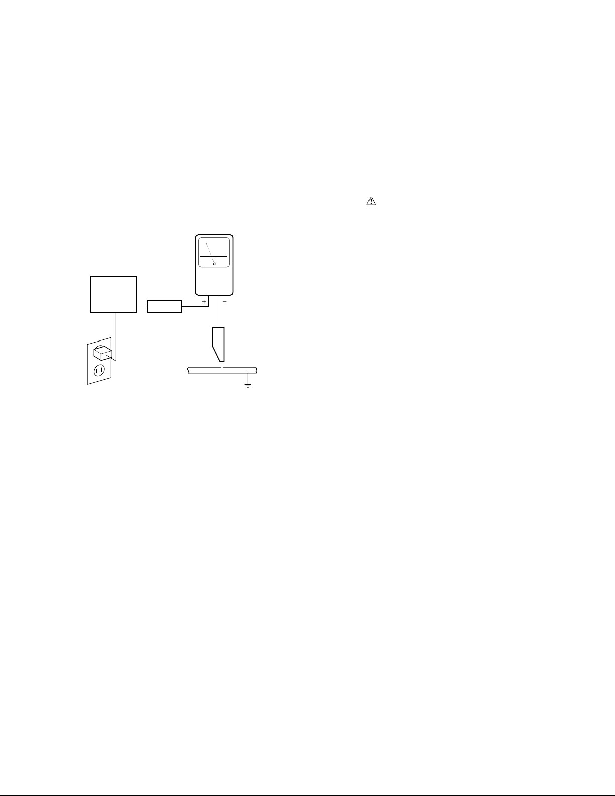
Leakage Current Hot Check
Plug the AC line cord directly into an AC power source (do not use
an isolation transformer for this check).
Turn the AC power switch on.
Using a "Leakage Current Tester (Simpson Model 229 equivalent)",
measure for current from all exposed metal parts of the cabinet
(input/output terminals, screwheads, metal overlays, control shaft,
etc.), particularly any exposed metal part having a return path to the
chassis, to a known earth ground (water pipe, conduit, etc.). Any
current measured must not exceed 0.5mA.
Reading should
not be above
0.5 mA
Earth ground
Device
under
test
Also test with plug
reversed
(Using AC adapter
plug as required)
Leakage
current
tester
Test all exposed
metal surfaces
AC Leakage Test
1.2 PRODUCT SAFETY NOTICE
Many electrical and mechanical parts in PIONEER set have special
safety related characteristics. These are often not evident from
visual inspection nor the protection afforded by them necessarily
can be obtained by using replacement components rated for higher
voltage, wattage, etc. Replacement parts which have these special
safety characteristics are identified in this Service Manual.
Electrical components having such features are identified by marking
with a
Manual.
The use of a substitute replacement component which dose not have
the same safety characteristics as the PIONEER recommended
replacement one, shown in the parts list in this Service Manual, may
create shock, fire or other hazards.
Product Safety is continuously under review and new instructions
are issued from time to time. For the latest information, always
consult the current PIONEER Service Manual. A subscription to, or
additional copies of, PIONEER Service Manual may be obtained at
a nominal charge from PIONEER.
on the schematics and on the parts list in this Service
ANY MEASUREMENTS NOT WITHIN THE LIMITS
OUTLINED ABOVE ARE INDICATIVE OF A POTENTIAL
SHOCK HAZARD AND MUST BE CORRECTED BEFORE
RETURNING THE SET TO THE CUSTOMER.
3
PDP-502MX, PDP-502MXE
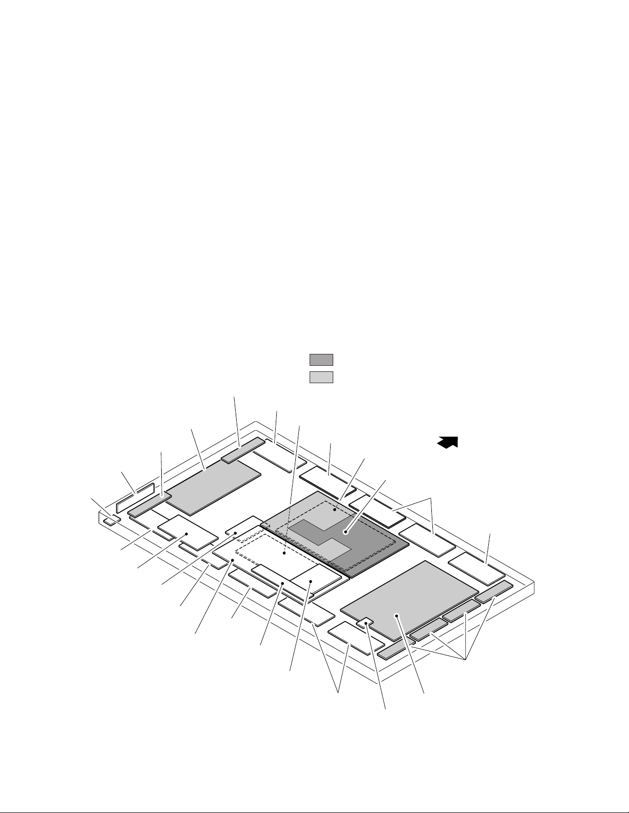
1.3 CHARGED SECTION AND HIGH VOLTAGE GENERATING POINT
7 Charged Section
The places where the commercial AC power is used without
passing through the power supply transformer.
If the places are touched, there is a risk of electric shock. In addition,
the measuring equipment can be damaged if it is connected to the
GND of the charged section and the GND of the non-charged
section while connecting the set directly to the commercial AC
power supply. Therefore, be sure to connect the set via an insulated
transformer and supply the current.
7 Charged Section
(Power supply primary side)
1. AC Power Cord
2. AC Inlet with Filter
3. Power Switch (S1)
4. Fuse (In the MAIN POWER ASSY)
5. STB Transformer and Converter Transformer
(In the MAIN POWER ASSY)
6. Other primary side of the MAIN POWER ASSY
X CABLE U ASSY
CABLE ASSY
X DRIVE ASSY
X CABLE D ASSY
SIDE SWITCH ASSY
7 High Voltage Generating Point
The places where voltage is 100V or more except for the charged
places described above. If the places are touched, there is a risk of
electric shock.
1. POWER SUPPLY MODULE (170V)
2. X DRIVE ASSY (170V)
3. Y DRIVE ASSY (–200V to 250V)
6. SCAN MODULE (250V)
For the places, refer to the EXPLODED VIEWS, the SCHEMATIC
DIAGRAM and the PCB CONNECTION DIAGRAM sections.
Part is charged section.
Part is the high voltage generating points other than the
charged section.
UCOM ASSY
CABLE ASSY
DIGITAL VIDEO ASSY
MAIN POWER ASSY
TOP
IR RECEIVER ASSY
CABLE ASSY
CONTROL ASSY
4
AUDIO ASSY
CABLE ASSY
VIDEO ASSY
CABLE ASSY
INPUT ASSY
YC SEPA. ASSY
CABLE ASSY
SP TERMINAL ASSY
CABLE ASSY
CABLE ASSY
SCAN MODULE
Y DRIVE ASSY

PDP-502MX, PDP-502MXE
5
PDP-502MX, PDP-502MXE
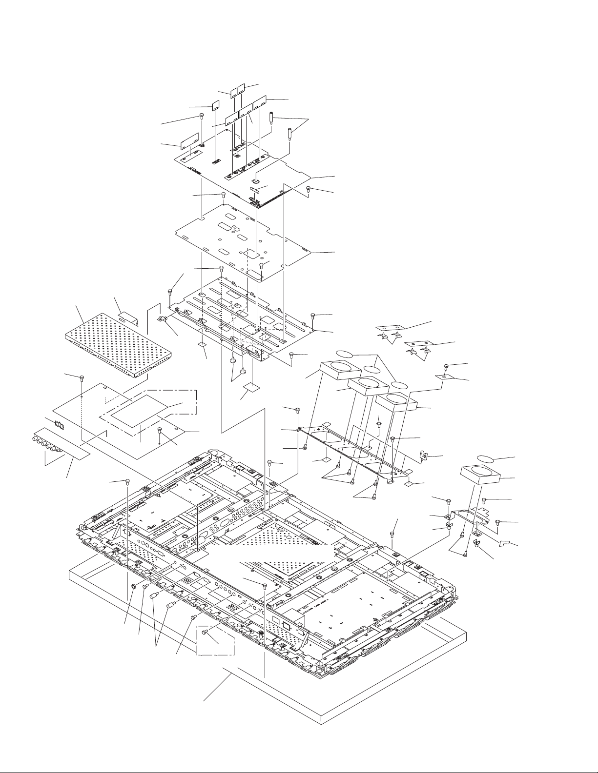
2. EXPLODED VIEWS AND PARTS LIST
NOTES : Parts marked by “ NSP ” are generally unavailable because they are not in our Master Spare Parts List.
The mark found on some component parts indicates the importance of the safety factor of the part.
Therefore, when replacing, be sure to use parts of identical designation.
Screw adjacent to mark on the product are used for disassembly.
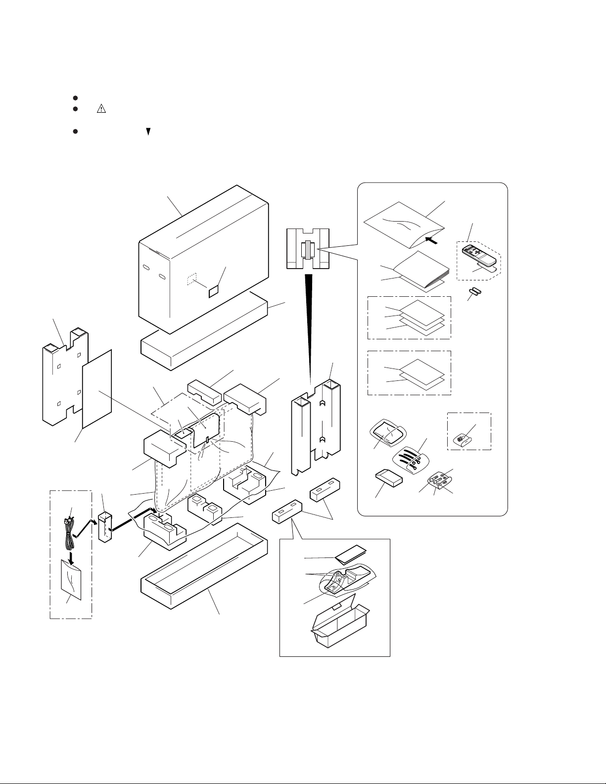
2.1 PACKING
10
42
11
8
7
14
26
PDP-502MX Only
4
9
12
5
21
20, 22
6
3
13
1
32
15
18
16
17
19
PDP-502MX Only
40
41
PDP-502MXE Only
28
36
37
30
24
25
27
PDP-502MX Only
39
38
29
23
31
30
PDP-502MX Only
6
2
11
35
34
33

(1) PACKING PARTS LIST
Mark No. Description Part No.
PDP-502MX, PDP-502MXE
Mark No. Description Part No.
1 Under Pad R AHA2239
2 Under Pad L AHA2240
3 Upper Pad R AHA2241
4 Upper Pad L AHA2242
5 Upper Pad C AHA2243
6 Under Pad C AHA2245
7 Front Carton AHB1210
8 Rear Carton AHB1211
9 Code Case AHC1033
10 Upper Carton
11 Under Carton AHD3037
12 Mirror Mat AHG1284
13 Polyethirene Sheet AHG1302
14 Protect Sheet SHC-925
15 Operating Instructions
16 Plasma Caution Sheet
17 Plasma Caution Sheet
18 Caution Sheet ARM1168
19 Caution Sheet
NSP 20 Warranty Card
NSP 21 Warranty Card
NSP 22 Vinyl Pouch
23 Remote Control Unit AXD1446
(CU-V159)
24 Battery Cover AZN2098
NSP 25 AA (R6/UM-3) Batteries
See contrast table (2)
See contrast table (2)
See contrast table (2)
See contrast table (2)
See contrast table (2)
See contrast table (2)
See contrast table (2)
See contrast table (2)
See contrast table (2)
26 AC Power Cord
27 Binder Assy AEC1758
28 Cleaning Cloth AED1174
NSP 29 Vinyl Bag (for Screw, Nut) AHG-064
NSP 30 Literature Bag AHG-117
31 Pin/BNC Conversion Adaptor
32 Diaplay Stand AMR3168
NSP 33 Stand Bracket ANG2351
34 Screw CPZ30P080FZK
35 Caution Sheet ARM1175
36 Remote Control Unit Case AMR3169
37 Hex Hole Bolt (M8×40) SMZ80H400FZB
38 Washer WAX1F200K320
39 Washer WB80FZB
40 Plasma Caution Sheet
41 EMC Caution Sheet
42 EMC Caution Label
See contrast table (2)
See contrast table (2)
See contrast table (2)
See contrast table (2)
See contrast table (2)
(2) CONTRAST TABLE
PDP-502MX/LUCBW and PDP-502MXE/YVLDK are constructed the same except for the following:
Part No.
Mark
10 Upper Carton AHD3035 AHD3043
15 Operating Instructions ARD1029 Not used
15 Operating Instructions Not used ARE1350
16 Plasma Caution Sheet ARM1145 Not used
17 Plasma Caution Sheet ARM1147 Not used
19 Caution Sheet ARM1176 Not used
NSP 20 Warranty Card ARY1093 Not used
NSP 21 Warranty Card ARY1102 Not used
NSP 22 Vinyl Pouch AHG–195 Not used
NSP 25 AA (R6/UM-3) Batteries AEX1025 VEM1011
26 AC Power Cord ADG1178 Not used
31 Pin/BNC Conversion Adaptor AKX1052 Not used
40 Plasma Caution Sheet Not used ARM1149
41 EMC Caution Sheet Not used ARM1164
42 EMC Caution Label Not used AAX2708
Symbol and DescriptionNo.
(English/French/Japanese)
(English/French/German/Italian/
Dutch/Spanish)
PDP-502MX PDP-502MXE
LUCBW YVLDK
Remarks
7

PDP-502MX, PDP-502MXE
2.2 REAR CASE SECTION
4
10
PDP-502MXE
Only
PDP-502MX
Only
16
10
22
4
9
12
4
20
21
4
7
9
10
9
4
9
9
10
4
8
4
10
4
28
9
9
4
5
PDP-502MX
Only
10
9
17
4
23 (MX)
27 (MXE)
9
7
4
27 (MX)
23 (MXE)
10
9
4
9
32
9
19 (MX)
30 (MXE)
12
31
29
PDP-502MXE
Only
PDP-502MX
Only
26
13
15
18
3
2
Refer to "2.3 EXTERIOR (1/3)".
6
11
PDP-502MX
Only
1
24
14
25
8
(1) REAR CASE SECTION PARTS LIST
PDP-502MX, PDP-502MXE
Mark No. Description Part No.
1 Siricon Sheet L AEH1031
2 Siricon Sheet S AEH1030
3 Barrier AMR3166
4 Screw BBZ40P160FZK
5 Rear Case Frame
NSP 6 Rear Case
7 Stand Bolt ABA1277
8 Screw Collar AEC1848
9 Screw AMZ30P100FZK
10 Hole Rivet AMR2969
11 Solder Warning Label
12 Screw Rivet AEC1852
13 Terminal Label D AAX2721
14 Terminal Label F AAX2723
15 Terminal Label G
16 Terminal Label A
17 Caution Label
18 Terminal Label C
19 Terminal Label B
20 Bolt Caution Label
See contrast table (2)
See contrast table (2)
See contrast table (2)
See contrast table (2)
See contrast table (2)
See contrast table (2)
See contrast table (2)
See contrast table (2)
See contrast table (2)
Mark No. Description Part No.
21 Cleaning Label
NSP 22 Name Label
NSP 23 UPC Code Label
NSP 24 Earth Label BAX1014
25 Serial Seal AAX2609
NSP 26 Display Label
NSP 27 Label VRW1629
28 Barrier Caution Label
29 Connector Cover
30 Earth Plate
31 Washer
32 Terminal Label N
(2) CONTRAST TABLE
PDP-502MX/LUCBW and PDP-502MXE/YVLDK are constructed the same except for the following:
See contrast table (2)
See contrast table (2)
See contrast table (2)
See contrast table (2)
See contrast table (2)
See contrast table (2)
See contrast table (2)
See contrast table (2)
See contrast table (2)
Part No.
Mark
Symbol and DescriptionNo.
PDP-502MX PDP-502MXE
LUCBW YVLDK
5 Rear Case Frame AMR3147 AMR3170
NSP 6 Rear Case ANE1581 ANE1587
11 Solder Warning Label AAX2644 Not used
15 Terminal Label G AAX2724 Not used
15 Terminal Label E Not used AAX2722
16 Terminal Label A AAX2718 Not used
16 Terminal Label L Not used AAX2734
17 Caution Label ARW1087 Not used
18 Terminal Label C AAX2720 Not used
18 Terminal Label M Not used AAX2735
19 Terminal Label B AAX2719 Not used
20 Bolt Caution Label AAX2727 AAX2728
21 Cleaning Label AAX2751 AAX2766
NSP 22 Name Label AAL2309 AAL2313
NSP 23 UPC Code Label AAX2712 AAX2749
NSP 26 Display Label AAX–359 Not used
28 Barrier Caution Label AAX2759 Not used
29 Connector Cover Not used ANG2355
30 Earth Plate Not used ANK1639
31 Washer Not used ABE1077
32 Terminal Label N Not used AAX2736
Remarks
9
PDP-502MX, PDP-502MXE
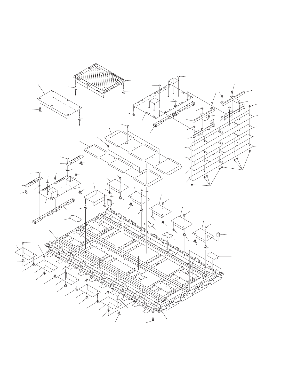
2.3 EXTERIOR (1/3)
5
34
28
11
23
PDP-502MX Only
21
20
16
40
33
34
24
34
21
25
36
38
2
12
24
34
32
21
35
13
31
34
32
22
13
34
1
20
8
19
7
15
14
15
34
34
31
21
30
9
27
32
13
32
10
18
34
17
14
13
20
30
29
27
39
37
26
6
4
3
Refer to "2.4 EXTERIOR (2/3)".
10
43
41
42
41
Refer to "2.6 FRONT CASE SECTION".
41
PDP-502MX Only

(1) EXTERIOR (1/3) SECTION PARTS LIST
PDP-502MX, PDP-502MXE
Mark No. Description Part No.
1 MAIN POWER ASSY AWZ6405
2 Fuse (10A, FU101) AEK1071
3 VIDEO ASSY
4 YC SEPA. ASSY
NSP 5 Analog Shield Cover ANK1601
6 PCB Spacer AEC1832
NSP 7 Chassis ANA1605
8 Insulating Sheet AMR3199
9 Fan Frame A ANG2330
10 Wire Saddle AEC1745
11 INPUT ASSY AWZ6394
NSP 12 Fan Frame C ANG2332
13 Fan Motor AXM1036
14 Fan Label AAX2746
15 Locking Card Spacer AEC1736
16 VF DD CONVERTER ASSY AWZ6412
17 SENSOR A ASSY AWZ6400
18 FAN CABLE A ASSY AWZ6403
19 FAN CABLE B ASSY AWZ6404
20 Screw BMZ30P060FCU
21 Screw BBZ40P160FZK
22 Spacer Screw AEF1028
23 Wire Barrier AMR3209
24 Nylon Rivet AEC1671
NSP 25 Powder Guard L AMR3201
See contrast table (2)
See contrast table (2)
Mark No. Description Part No.
31 Fan Angle Cushion AED1193
32 Screw PPZ50P100FZK
33 PCB Hinge AEC1807
34 Screw AMZ30P060FMC
35 RCC CONTROL A ASSY AWZ6406
36 RCC CONTROL B ASSY AWZ6407
37 RCC CONTROL C ASSY AWZ6408
38 OTL CONTROL A ASSY AWZ6409
39 OTL CONTROL B ASSY AWZ6410
40 OTL CONTROL C ASSY AWZ6411
41 Screw BPZ30P080FZK
42 Hexagon Screw BBA1051
43 Nut ABN1033
NSP 26 Powder Guard S AMR3200
27 PCB Mold AMR2115
28 2P Earth Plate ANK1156
29 Fan Cushion AEC1840
30 Screw ABZ30P140FMC
(2) CONTRAST TABLE
PDP-502MX/LUCBW and PDP-502MXE/YVLDK are constructed the same except for the following:
Part No.
Mark
3 VIDEO ASSY AWZ6441 AWZ6448
4 YC SEPA. ASSY AWV1776 Not used
Symbol and DescriptionNo.
PDP-502MX PDP-502MXE
Remarks
LUCBW YVLDK
11

PDP-502MX, PDP-502MXE
2.4 EXTERIOR (2/3)
22
18
28
20
23
23
40
31
30
32
36
22
22
21
11
35
22
10
12
9
9
44
A
43
1
39
9
22
1
25
B
1
8
22
10
7
42
6
1
1
5
3
21
22
22
33
16
23
41
24
23
23
23
23
15
29
13
22
21
4
38
26
4
5
26
A
Refer to "2.5 EXTERIOR (3/3)".
B
12
40
23
41
13
14
19
37
22
22
3
2
5
19
1
1
12
1
1
1
22
21
22
5
4
22
4
(1) EXTERIOR (2/3) SECTION PARTS LIST
PDP-502MX, PDP-502MXE
Mark No. Description Part No.
1 Frame Shield H ANK1609
2 Frame H ANG2343
3 Frame V ANG2344
4 Frame Shield V ANK1610
5 Corner Holder ANG2347
6 Ferrite Core (L1) ATX1037
7 Sub Frame R ANG2334
8 Sub Frame L ANG2333
9 Bush C AEC1740
10 Wire Saddle AEC1745
11 AC Inlet with Filter (CN1)
12 Shield Gasket B ANK1612
13 Shield Gasket D ANK1614
14 Shield Gasket C ANK1613
15 Terminal Panel
16 Shield Gasket E ANK1634
17 ……………………………
NSP 18 IR Holder ANG2346
19 Edging Saddle AEC1737
20 Nylon Rivet AEC1671
21 Screw AMZ30P080FCU
22 Screw AMZ30P060FMC
23 Screw BMZ30P060FCU
24 Hexagon Screw BBA1051
25 Ferrite Core Holder AEC1818
See contrast table (2)
See contrast table (2)
Mark No. Description Part No.
NSP 31 Control Shield Case ANK1626
NSP 32 Control Shield Cover ANK1627
NSP 33 Control Shield Plate ANG2380
34 ……………………………
35 SP TERMINAL ASSY AWZ6415
36 PCB Support AEC1270
37 Spacer AEC1847
38 Screw AMZ30P100FZK
NSP 39 Drive Voltage Label ARW1077
40 Screw BPZ30P080FZK
41 Nut ABN1033
42 Screw PMB40P080FMC
43 Ferrite Core (L2) ATX1031
44 Binder AEC1851
26 FPC Cushion AEB1341
27 ……………………………
28 IR RECEIVER ASSY AWZ6399
29 Power Switch (S1) BSM1006
30 CONTROL ASSY AWZ6414
(2) CONTRAST TABLE
PDP-502MX/LUCBW and PDP-502MXE/YVLDK are constructed the same except for the following:
Part No.
Mark
11 AC Inlet with Filter (CN1) AKP1202 AKP1193
15 Terminal Panel ANG2341 ANG2353
Symbol and DescriptionNo.
PDP-502MX PDP-502MXE
Remarks
LUCBW YVLDK
13
PDP-502MX, PDP-502MXE
2.5 EXTERIOR (3/3)
22
11
30
13
34
23
18
27
45
43
26
25
11
36
39
22
39
39
23
11
18
24
27
39
22
39
43
37
43
18
27
39
21
35
24
43
44
40
18
27
26
25
38
22
23
16
28
11
22
39
41
12
9
39
11
39
23
22
34
B
17
28
39
29
9
39
14
3
39
41
39
15
35
28
A
28
46
46
23
11
2
39
20
19
A
B
1
30
29
39
32
38
33
9
14
23
11
22
23
11
22
39
23
11
22
39
23
11
22
39
23
21
31
(×40)
34
42

(1) EXTERIOR (3/3) SECTION PARTS LIST
PDP-502MX, PDP-502MXE
Mark No. Description Part No.
NSP 1 Panel Shield S ANK1633
NSP 2 Panel Shield L ANK1632
NSP 3 Frame Assy ANA1626
NSP 19 Tube Cover AMR3036
NSP 20 Push Rivet AEC1748
4 ……………………………
5 ……………………………
6 ……………………………
7 ……………………………
8 ……………………………
9 PCB Spacer AMR3155
10 ……………………………
11 CABLE ASSY AWV1816
12 Y DRIVE ASSY AWV1818
13 X CABLE D ASSY AWZ6397
14 X DRIVE ASSY AWV1817
15 X CABLE U ASSY AWZ6396
16 DIGITAL VIDEO ASSY AWV1815
17 UCOM ASSY
18 SCAN MODULE (IC41–IC44) MC-16343
21 Insulator AEZ1013
22 PCB Mold AMR2115
23 Locking Spacer AEC1794
24 Screw Grommet AEC-905
25 Insulating Sheet AMR3156
See contrast table (2)
Mark No. Description Part No.
31 Plastic Rivet AMR1066
32 AUDIO ASSY AWZ6413
NSP 33 PCB Spacer AEC1446
NSP 34 Blind Sheet S AMR3202
NSP 35 Blind Sheet L AMR3203
NSP 36 Hot Plate A ANG2338
NSP 37 Hot Plate B ANG2339
38 Circuit Board Spacer AEC1795
39 Screw ABZ30P160FCU
40 Screw INC30P100FZK
41 Screw IBZ30P250FCU
42 Plasma Panel Assy AAV1236
43 Screw ABZ30P080FCU
44 Hot Plate Barrier A AMR3210
45 Hot Plate Barrier B AMR3211
46 Screw ABZ30P060FCU
NSP 26 Scan Heat Sink ANH1558
27 Silicone Sheet AEH1028
NSP 28 Circuit Board Spacer AEC1744
29 Earth Plate (KN1, KN2) ANK-142
30 Locking Spacer AEC1796
(2) CONTRAST TABLE
PDP-502MX/LUCBW and PDP-502MXE/YVLDK are constructed the same except for the following:
Part No.
Mark
17 UCOM ASSY AWZ6395 AWZ6473
Symbol and DescriptionNo.
PDP-502MX PDP-502MXE
Remarks
LUCBW YVLDK
15
PDP-502MX, PDP-502MXE
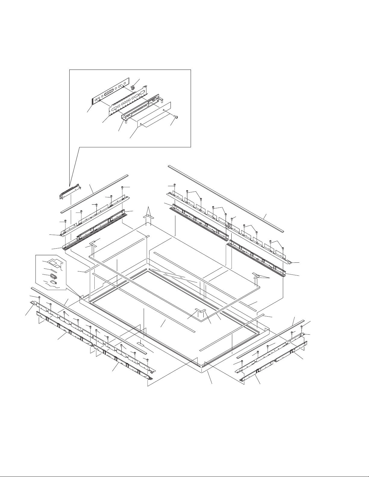
2.6 FRONT CASE SECTION
3
4
5
2
22
1
18
8
8
8
8
17
20
7
23
6
15
8
8
7
9
19
13
10
8
8
19
8
9
8
14
16
8
8
21
11
8
9
14
8
14
8
8
12
8
10
8
8
7
18
9
8
8
17
16
14
11
13
8
8
16
15
16

(1) FRONT CASE SECTION PARTS LIST
Mark No. Description Part No.
1 SIDE SWITCH ASSY AWZ6398
2 LED Lens AAK2695
3 Control Name Plate AAK2757
4 Control Shield ANK1606
5 Control Button AAC1540
PDP-502MX, PDP-502MXE
NSP 7 Panel Holder Assy ANG2386
NSP 17 Panel Holder V ANG2337
NSP 20 Panel Shield VM ANK1605
6 Lens AAK2741
8 Screw BPZ30P080FZK
9 Panel Shield H ANK1603
10 Panel Cushion H AED1189
11 Front Cushion H AED1191
12 Protect Panel Assy AMR3163
13 Front Cushion V AED1192
14 Corner Cushion AEB1360
15 Front Case
16 Panel Shield V ANK1604
18 Panel Cushion V AED1190
19 Corner Gasket ANK1635
21 Pioneer Seal
22 Screw BBZ30P080FMC
23 Shield ANK1640
See contrast table (2)
See contrast table (2)
(2) CONTRAST TABLE
PDP-502MX/LUCBW and PDP-502MXE/YVLDK are constructed the same except for the following:
Part No.
Mark
Symbol and DescriptionNo.
PDP-502MX PDP-502MXE
Remarks
LUCBW YVLDK
15 Front Case AMB2649 AMB2672
21 Pioneer Seal ARW1091 Not used
17
1
234
PDP-502MX, PDP-502MXE
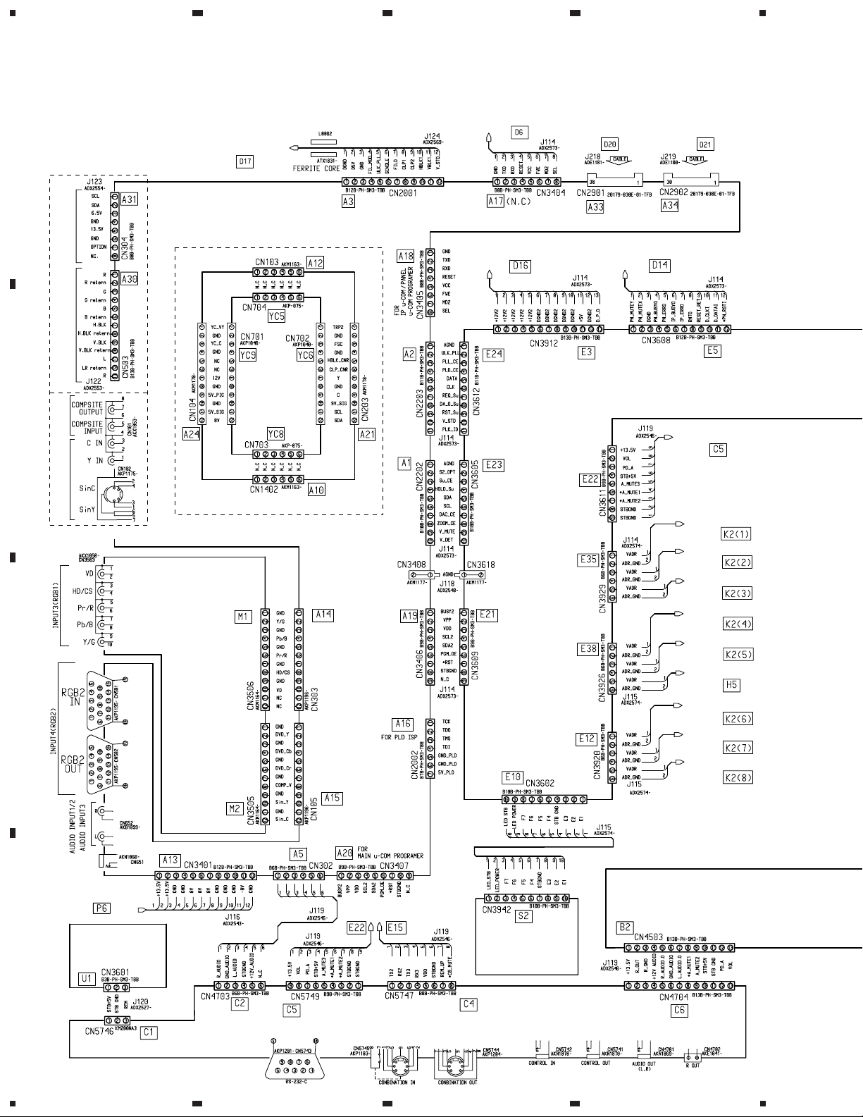
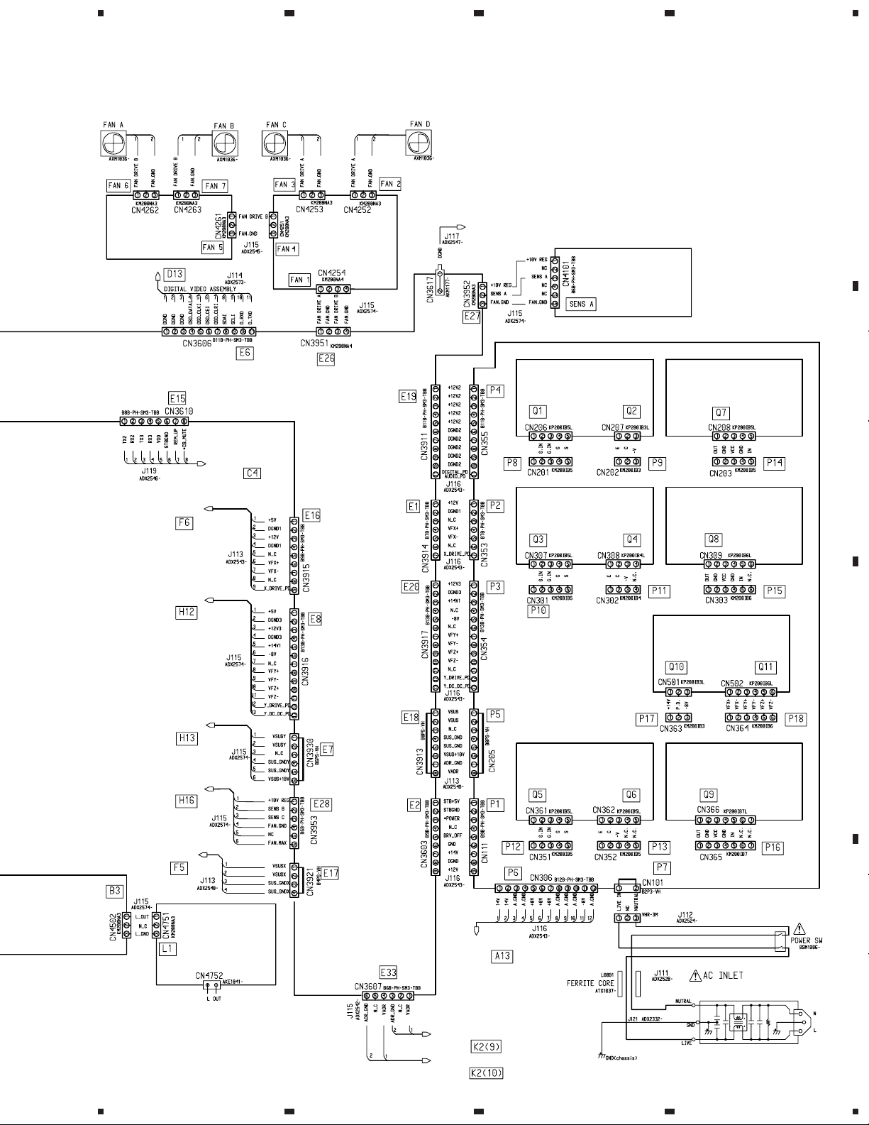
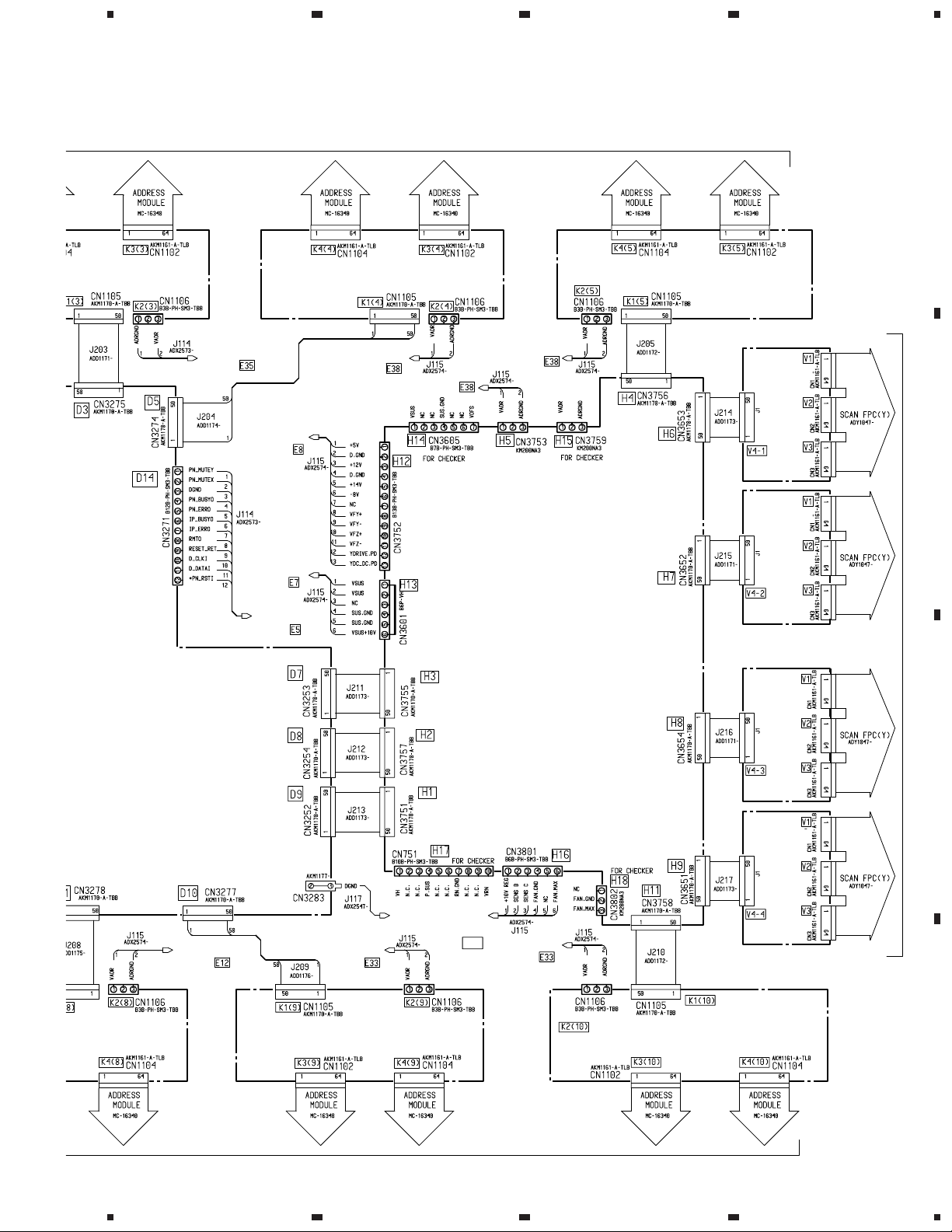
3. OVERALL CONNECTION DIAGRAM AND BLOCK DIAGRAM
3.1 OVERALL CONNECTION DIAGRAM (1/2)
A
PDP-502MXE Only
To PDA-5001 (VIDEO BOX)
B
PDP-502MX Only
INPUT ASSY
(AWZ6394)
C
DIGITAL VIDEO ASSY
CN3402
VIDEO ASSY
(AWZ6441: PDP-502MX)
(AWZ6448: PDP-502MXE)
YC SEPA.
ASSY
(AWV1776)
PDP-502MX Only
DIGITAL VIDEO ASSY
CN2301
DIGITAL VIDEO ASSY
CN551
UCOM ASSY
(AWZ6395: PDP-502MX)
(AWZ6473: PDP-502MXE)
DIGITAL VIDEO ASSY
CN3403
DIGITAL VIDEO ASSY
CN3271
DIGITAL VIDEO ASSY
CN3404
CONTROL ASSY
CN5749
CABLE ASSY (1)
CN1106
CABLE ASSY (2)
CN1106
CABLE ASSY (3)
CN1106
CABLE ASSY (4)
CN1106
CABLE ASSY (5)
CN1106
Y DRIVE ASSY
CN3753
CABLE ASSY (6)
CN1106
CABLE ASSY (7)
CN1106
CABLE ASSY (8)
CN1106
MAIN POWER ASSY
CN306
IR RECEIVER
ASSY
D
(AWZ6399)
UCOM ASSY
CN3611 CN3610
SIDE SWITCH
ASSY
(AWZ6398)
AUDIO ASSY
(AWZ6413)
CONTROL ASSY
(AWZ6414)
18
1234
5
67
8
PDP-502MX, PDP-502MXE
Note: When ordering service parts, be sure to refer to "EXPLODED VIEWS AND PARTS LIST" or "PCB PARTS LIST".
A
FAN CABLE B
ASSY
(AWZ6404)
X DRIVE ASSY
CN3451
Y DRIVE ASSY
CN3601
CONTROL ASSY
CN5747
FAN CABLE A
ASSY
(AWZ6403)
DIGITAL VIDEO ASSY
CN3283
RCC CONTROL (A)
ASSY (AWZ6406)
RCC CONTROL (B)
ASSY (AWZ6407)
SENSOR A ASSY
(AWZ6400)
OTL CONTROL (A)
ASSY (AWZ6409)
B
OTL CONTROL (B)
ASSY (AWZ6410)
Y DRIVE ASSY
CN3601
Y DRIVE ASSY
CN3801
X DRIVE ASSY
CN3451
SP TERMINAL
ASSY
(AWZ6415)
VF DD CONVERTER
MAIN POWER ASSY
ASSY (AWZ6412)
(AWZ6405)
C
OTL CONTROL (C)
ASSY (AWZ6411)
AKP1202: PDP-502MX
AKP1193: PDP-502MXE
D
VIDEO ASSY
CN3401
CABLE ASSY (9)
CN1106
CABLE ASSY (10)
CN1106
RCC CONTROL (C)
ASSY (AWZ6408)
19
5
6
7
8

1
234
PDP-502MX, PDP-502MXE
3.2 OVERALL CONNECTION DIAGRAM (2/2)
A
To PLASMA PANEL ASSY
CABLE ASSY (1)
(AWV1816)
B
To PLASMA PANEL ASSY
UCOM ASSY
CN3921
X CABLE U ASSY
(AWZ6396)
X DRIVE ASSY
(AWV1817)
UCOM ASSY
CN3929
VIDEO ASSY
CN2001
UCOM ASSY
CN3606
UCOM
ASSY
CN3915
J124
ADX2669-
CABLE ASSY (2)
(AWV1816)
UCOM
ASSY
CN3929
DIGITAL VIDEO ASSY
(AWV1815)
CABLE ASSY (3)
(AWV1816)
VIDEO ASSY
CN3404
C
VIDEO ASSY
X CABLE D ASSY
(AWZ6397)
CABLE ASSY (6)
(AWV1816)
UCOM
ASSY
CN3920
UCOM ASSY
CN3912
CABLE ASSY (7)
(AWV1816)
CN2901 CN2902
UCOM ASSY
CN3920
CABLE ASSY (8)
(AWV1816)
D
To PLASMA PANEL ASSY
20
1234
5
67
8
PDP-502MX, PDP-502MXE
A
)
UCOM ASSY
CN3929
UCOM ASSY
CN3916
UCOM ASSY
CN3930
UCOM ASSY
CN3608
CABLE ASSY (4)
(AWV1816)
UCOM ASSY
CN3926
UCOM ASSY CN3926
UCOM ASSY
CN3926
Y DRIVE ASSY
(AWV1818)
CABLE ASSY (5)
(AWV1816)
SCAN MODULE
(MC-16343)
SCAN MODULE
(MC-16343)
B
To PLASMA PANEL ASSY
UCOM ASSY
CN3920
5
UCOM ASSY
CN3607
CABLE ASSY (9)
(AWV1816)
UCOM ASSY
CN3617
6
UCOM
ASSY
CN3953
E28
UCOM ASSY
CN3607
CABLE ASSY (10)
(AWV1816)
7
SCAN MODULE
(MC-16343)
SCAN MODULE
(MC-16343)
8
C
D
21

PDP-502MX, PDP-502MXE
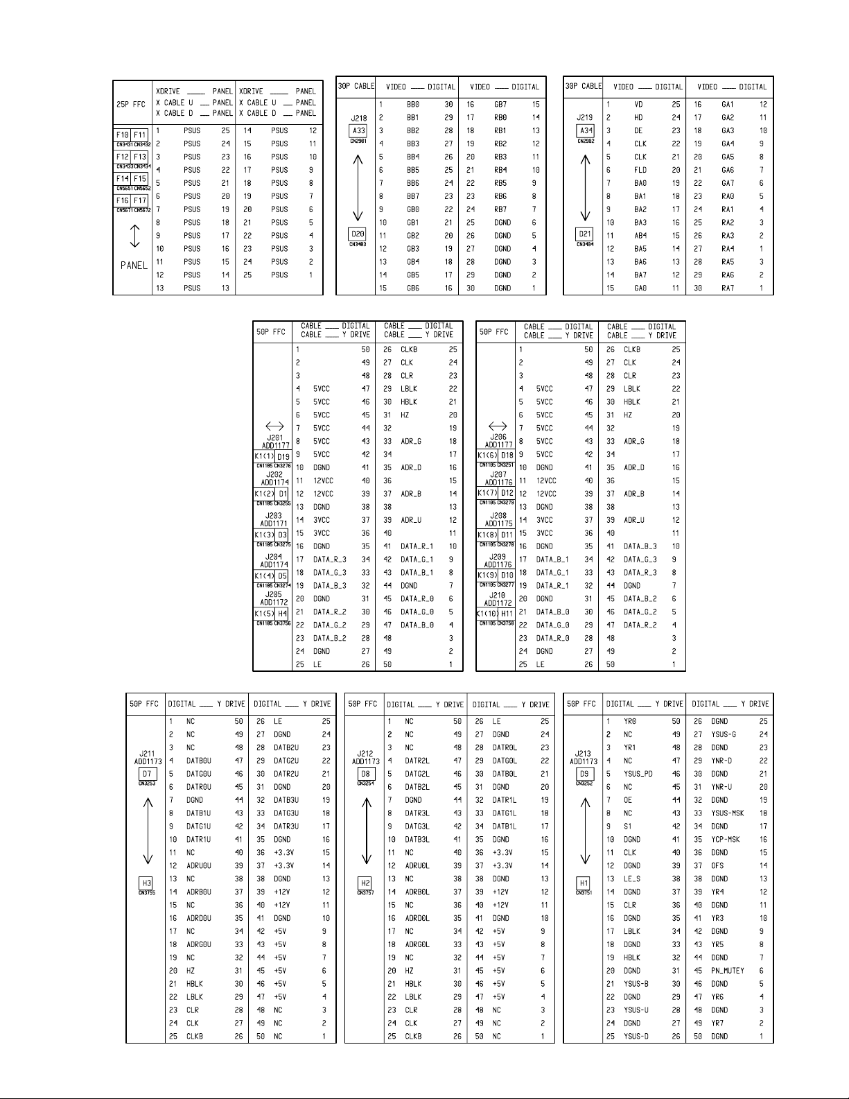
Each Flexible Flat Cable Terminal Name
22
PDP-502MX, PDP-502MXE
23
1
C
4
s
C
F
S
Y
P
L
R
Y
S
S
Y
A
C
1
5
3
234
PDP-502MX, PDP-502MXE
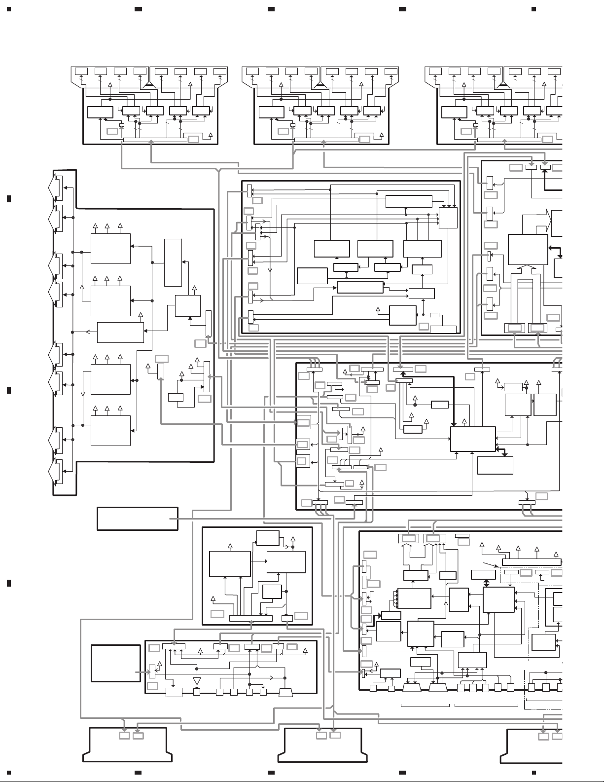
3.3 BLOCK DIAGRAM
3.3.1 OVERALL BLOCK DIAGRAM
IC IC IC IC
VADR
RGB
RGB
RGB
IC IC IC IC
RGB
RGB
RGB
VADR
RGB
RGB
IC IC IC IC
VADR
RGB
RGB
RGB
IC IC IC IC
RGB
RGB
RGB
VADR
RGB
RGB
IC IC IC IC
VADR
RGB
RGB
RGB
RGB
IC IC IC
VADR
RGB
RGB
RGB
ADR
U/B/
D/G
VADR
Gen.
CLKB CLKBCLK
DEF DEF DEF DEF
VADR
K2
DAT3
(64bit)
DAT2
(64bit)
DAT1
(64bit)
DAT0
A
(64bit)
CLK
12V
5V
3.3V
K1
CABLE ASSY
CABLE ASSY
ADR
U/B/
D/G
VADR
Gen.
CLKB CLKBCLK
DEF DEF DEF DEF
VADR
K2
DAT3
(64bit)
DAT2
(64bit)
DAT1
(64bit)
DAT0
(64bit)
ADR
U/B/
D/G
VADR
Gen.
CLKB CLKBCLK
DEF DEF DEF DEF
VADR
K2
DAT3
(64bit)
DAT2
(64bit)
DAT1
(64bit)
DAT0
(64bit)
K1
CLK
12V
5V
3.3V
K1
CABLE ASSY
D13 D1
E6
S5V
SYSTEM
IC3604
D1
D19
D4
D18
D12
14V
OSD DAT
FAN
MAX
SENS
EEPROM
IC3601
Process
CLP Pulse
RGB A DAT
D20 D21
R10V
REG
FAN
CONT
BLK
SD
Vadr
RGB
DAT
IP
Gen.
RGB B DAT,HD,VD
Vadr
14V
FAN
DRV
E33
A
CLP
D17
P5
P2
Vsus
12VVfx
Sustain
SUS
Psus(X)
OUT
Pulse Gen.
IC3454
12V
Vfx
B
To Panel X-Electrode
Psus(X)
+RST
OUT
Sustain
Pulse Gen.
IC3455
+ Reset Pulse
12VVfx
Sustain
Pulse Gen.
IC3459
12VVfx
Vsus
Gen.
Vsus
Vsus
SUS
Vsus
Vsus
Isolation (PC)
RST
F5
OC
BLK
Logic
BLK
12V
Vfx
PD
DRV
Sig.
5V
F9
5V
F6
Psus(X)
Sustain
Pulse Gen.
SUS
OUT
IC3460
To Panel X-Electrode
X DRIVE ASSY
C
P3
P6
P4
HI PWR
OFF SW
PWR
P1
MAIN POWER ASSY
E35
E18
Vsus
E17
E7
Vsus
Vadr
E12
Vsus
VSUS
SW PWR
PD
Vadr
E21
E1
E22
VFX
VFY, VFZ
Vsus
10V
STB5V
5V
SDA
E10
SCK
VADR
SW PWR
PD CONT
STB12V
E3
E19
E24
E23
5V
E16
E20
5V
E8
VF D-D CON
Vadr
12V
DELAYDELAY
PD
STBY
PWR
12V
5V
E2
PD
13V
REM, Tx, Rx,Vol, Mute
E15
KEY, LED
8V
14V
VCC
SW PWR
+B
PFC
Relay
FU101
P7
E5
S5V
14V
R5V
REG
DAT, CLK
SDet, FDet
OC
OVC
-8V
AC IN
PWR
RST
CONT CPU
U-COM ASSY
TO SIDE SW
ASSY
AUDIO ASSY
12V
VOL
CONT
(Main/Sub)
12V
STB5V
LR
MUTE
LR
VOL
13V
B2
REM
R
R OUT
13V,S5V
PD, VOL
Audio
Out
Combi
In Out
IR
RECEIVE
D
ASSY
C6
S5V
C1
PD
C5
SRInSR
D-D
CON
PWR AMP
DC
DET
R
C4
Out
15V
IC4502
L
C2
LR
Tx
Rx
B3
12V
A19
A1
A2
A3
A5
Audio
A20
3/4
SDet
DAT
CLK
12V
DAC
Sync
U-Com
F-DET
CLP,HV
SEL
Audio
1/2
A33 A34
(A)
ADC
RGB
WB/BRI/
CONTROL
BLK
LRLR
RGB
OUT
RGB
CON
Sync
SEL
CONT
P&P
HD,VD
IN 4
(B)
CLK
RGB
RGB
In
CLK
HD
VD
PLL
Sync
Sepa
A17
HD
Int/
Ext
SEL
CLP,HV
BLK
R
Pr
9V_PIC
12V
9V_SIG
502MXE
VD
Only
V.ROM
RGB
RGB
Decoder
RGB
IC1401
Y
G/Y
In3/In4
SEL
ANALOG VIDEO ASS
HD
GYB
CS
Pb
IN 3
5VBPLL
RGB
YPbPr
HDVD
5APLL
-5V_IO
5V_AD
REG
A30 A31
YCbCr
YPbPr
SCL, SD
Sync
SEL
CSVD
IN 2
5V_
5V_
5_P
Y,
24
K1
K2
CABLE ASSY
CABLE ASSY
1234
K2
K1
K2
K1
CABLE AS
 Loading...