

Page 1

PPIONEER IONEER PPLASMA LASMA DDISPLAY ISPLAY SSYSTEMYSTEM
QUICK REFERENCE MANUAL
PDP-501HD: PLASMA DISPLAY PANEL
PDP-501R: MEDIA RECEIVER
PDP-501S-LR: SPEAKERS
TTABLE OF ABLE OF CCONTENTSONTENTS
1.0 CHOOSE THE INSTALLATION SITE...........................................................................................2
2.0 SET UP THE DISPLAY & THE MEDIA RECEIVER ........................................................................2
3.0 MOUNT THE SPEAKERS ON THE DISPLAY ................................................................................3
4.0 SECURE THE DISPLAY TO A BASE AND/OR A WALL ..................................................................4
5.0 THE MEDIA RECEIVER...........................................................................................................5
6.0 THE PLASMA DISPLAY ..........................................................................................................7
7.0 WIRING DIAGRAM.................................................................................................................8
8.0 OPERATING INSTRUCTIONS..................................................................................................10
9.0 THE REMOTE CONTROL UNIT...............................................................................................11
Page 2

Quick Start Installation Instructions
1. CHOOSE THE INSTALLATION SITE
The installation site should provide the best combination of the following properties:
ü Both units are positioned away from direct sunlight
ü The Plasma Display has sufficient ventilation
(approximately 8” or more on all sides)
ü Distance between the display and the media receiver does not exceed the
length of the provided cable
(contact your Pioneer Representative if additional distance is needed)
2. SET UP THE DISPLAY & THE MEDIA RECEIVER
1) Unpack the Media Receiver and remove all packing materials from the area
2) Position the Media Receiver
3) Unpack the Display and remove all packing materials from the area
(the display is extremely fragile and very heavy, at least 2 people are required)
4) Position the Display
t
The Media Receiver produces significant heat. Please do not put any
t
objects on top of the unit or block the ventilation flow.
t
The enclosed stand is designed to safely support the Plasma Display.
t
Only a qualified technician should attempt to remove the stand or any
other components from the Display.
Page 2
Page 3
Quick Start Installation Instructions
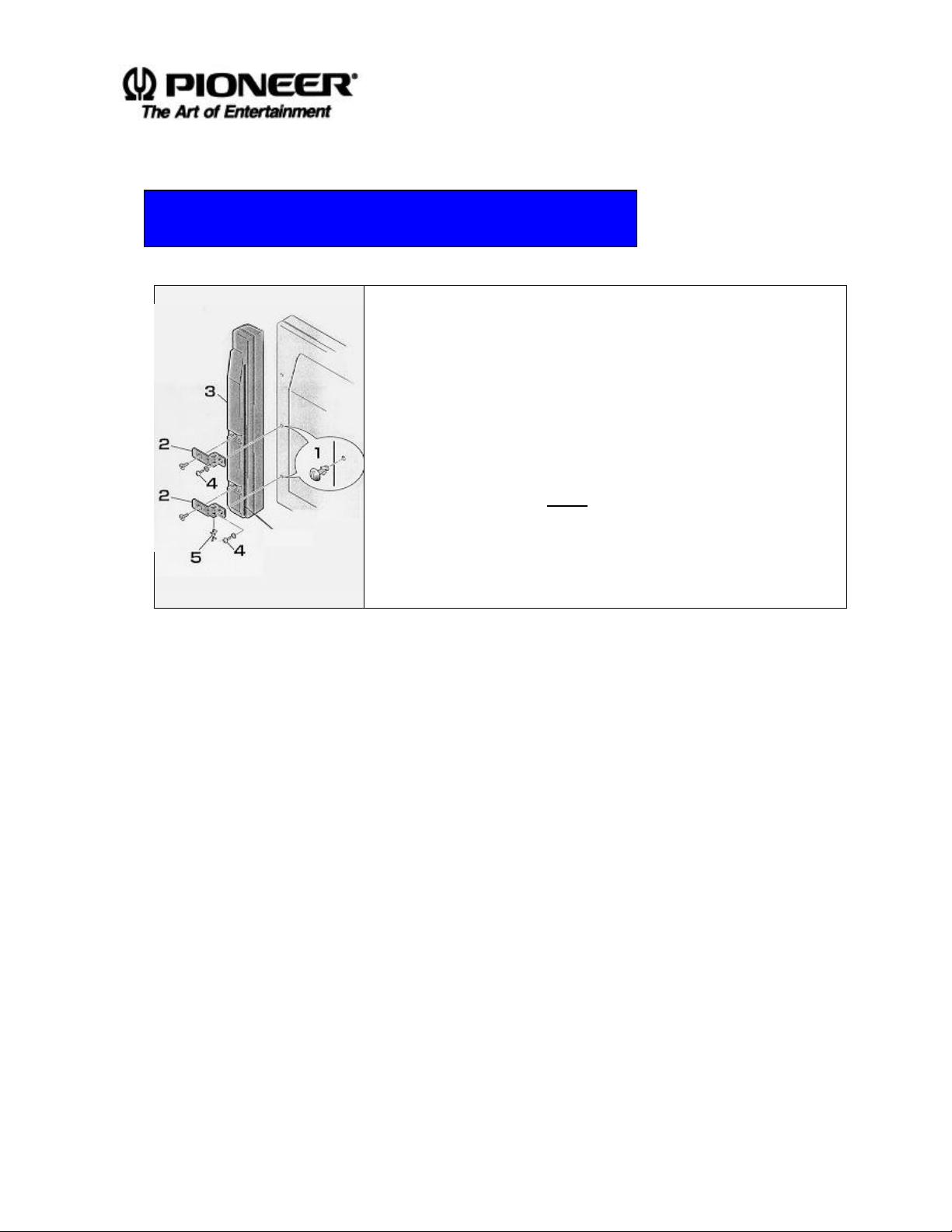
3. MOUNT THE SPEAKERS ON THE DISPLAY
1) Remove the 2 screws from the hole-plugs on each side
of the Display
(1st and 2nd hole-plugs from the bottom)
2) Connect the brackets to the speakers
(re-attach the small cushion pads if necessary)
3) Mount the speakers on the Display from the bottom
bracket to the top
(Set all screws in place before tightening the brackets to the Display)
4) Hold the speakers firmly against the Display while
tightening the screws
(do not over-torque the mounting screws)
5) Attach the speaker wire-retaining clip as noted in the
drawing
t
Speakers should not be used as handles to move the Display. To move
t
the unit, hold the bottom corners while stabilizing the top.
t
Pressing on the front cover of the speakers may cause damaged.
t
t
Avoid inserting objects or fingers into the speaker grill.
t
Page 3
Page 4
Quick Start Installation Instructions
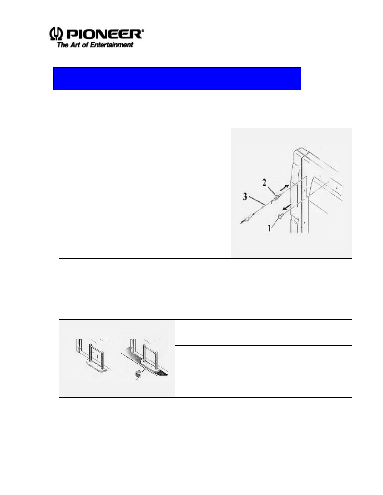
4. SECURE THE DISPLAY TO A BASE AND/OR A WALL
Follow the instructions listed below to secure the Display to a wall:
1) Remove the Securing hole-plugs from the upper
corners of the Display
2) Affix a support bolt and cable to either securing
hole on the Display
(contact your Pioneer Representative for purchase
information)
3) Fasten the end of the cable to a pillar or a wall
(some walls may require hooks sunk into an internal support
structure)
4) Repeat the process for the opposite side if needed
for additional support
Follow the instructions listed below to secure the Display to a base:
1) Position the Display on a base
(at least 1 person should support the Display at all times)
2) Place screws through the stand to the base*
(Set all screws in place before tightening the Display to the base)
3) Hold the Display while tightening the screws
Stand with screws Stand with clamp
* Clamps may be substituted to avoid drilling screw holes for the Display stand.
(do not over-torque the base screws)
Page 4
Page 5

5. THE MEDIA RECEIVER
Stand-By Indicator
Open/Close the Front Door
Main Power Button
Headphone Output Terminal
Input Selector
Volume Controller
TV Channel Selector
Clear Button
Front Input Selector
Computer Input Terminal
Video Input Terminal
Media Receiver PDP-501R
The light turns red when the Power
button is pressed and turns green
when the unit is functioning.
Quick Start Installation Instructions
Push the upper right corner to open the door.
Push and hold the front door to close.
Input options are in the following order:
TV > CS > DVD/LD > Video1 >Video 2 >
Front > HD > Computer > MUSE
Speaker automatically turns off
when this terminal is used.
Push once to turn on the power.
Push again to turn off the power.
Select Front Input Computer and Video.
Select aTV channel with the ±± button.
Change the audio with the ±± button.
Computer connection
Initialize all functions to the factory default settings
when this button is pressed for more than 2 seconds.
Connect a Video Player
(i.e. Video Camera, Game Player, etc)
Page 5
Page 6

Quick Start Installation Instructions
15pin for Video signal & RCA pin for Audio signal
1. VF/UHF Input Terminal
connect VHF/UHF broadcasting antenna
input
2. Control Input Terminal
connect other Pioneer equipment and control
with a single remote control unit
3. BS-IF Input Terminal
connect BS (Broadcasting-Satellite) antenna
input
4. M-N Converter Input Terminal
connect MUSE to NTSC converter
5. BS Decoder Output
connect BS (Broadcasting-Satellite) decoder
6. BS Decoder Input Terminal
connect BS (Broadcasting-Satellite) decoder
7. CS Input Terminal
connect another VCR or CLD player, etc
in/output
10. DVD Player Input Terminal
connect DVD or LD player
11. MUSE Input Terminal
connect MUSE LD player
12. Y/Pb/Pr Input Terminal
connect HD player
13. Computer Input Terminal
14. MUSE Decoder Output Terminal
connect to MUSE VCR, etc
15. System Cable Terminals
15D-sub pin/4 pin Din/8 pin to Plasma display
and Speaker cables to Speakers
16. Audio In/Output Terminal
connect to an audio amplifier
8. Video 1 In/Output Terminals
connect VCR deck in/output
9. Video 2 In/Output Terminal
connect another VCR or CLD player, etc
in/output
17. Sub-Woofer output Terminal
connect to a powered sub-woofer
Page 6
Page 7

6. THE PLASMA DISPLAY
Stand-By Indicator
Speaker (PDP-501S-LR)
Main Power Switch
Plasma Display PDP-501HD
Quick Start Installation Instructions
Install Left and Right Speakers
Light appears red when the power button is pressed
and changes to green when the unit is functional.
Turn the power ON and OFF.
Page 7
Page 8

Quick Start Installation Instructions
Rear Side of the Media Receiver (PDP-501R)
Remember to connect
Connectors from Left to Right:
after connecting
7. WIRING DIAGRAM
The wiring instructions for the Media Receiver, Plasma Display and the Speakers are
shown below:
Connect the System Cable to the Media Receiver (PDP-501R). Then, connect the short
Speaker Cable to the Media Receiver.
A) to 8pin DIN Control Output
B) to 4pin DIN Video 1 Output
C) to 15pin D-Sub Video 2 Output
D) Ground (GND)
E) to Left Speaker Terminals
(tied black and white cables)
F) to Right Speaker Terminals
(tied black and red cables)
Tighten screws
USE 100VAC ONLY
Use separately packaged
step-down transformer to
convert 220-240V to 100V
A B C D E F
the GND cable
NOTE: DO NOT plug in the Power Cable before all other cables are connected to the units.
Page 8
Page 9

Quick Start Installation Instructions
after connecting
Remember to connect
Connectors from Left to Right:
Connect the System Cable to the Plasma Display (PDP-501HD).
Rear side of the Plasma Display (PDP-501HD)
Please refer to the drawing to locate correct terminals.
NOTE: DO NOT plug in the Power Cable before all other cables are connected to the units.
A
A) to Right Speaker Terminals
(tied black and red cables)
B) to 15pin D-Sub Video 2 Output
C) Ground (GND)
D) to 8pin DIN Control Output
E) to 4pin DIN Video 1 Output
F) to Left Speaker Terminals
(tied black and white cables)
Tighten screws
B C D E F
USE 100VAC ONLY
Use separately packaged
step-down transformer to
convert 220-240V to 100V
the GND cable
Page 9
Page 10

Quick Start Installation Instructions
8. OPERATING INSTRUCTIONS
To turn on the PDP-501 system, following the instructions listed below:
Color of the Indicator
Turn on the power in following order only
Media Receiver Plasma Display
Turn the power ON to the Media Receiver Flashing Yellow
1
No Action
Turn the power ON to the Plasma Display
Flashing Yellow
to Green
Green
2
Once both units have been turned ON, continue with the procedure
Press the Power On button on the Remote Control Green to Red Green to Red
3
The PDP-501 is now in Stand-By mode
To turn the power OFF, press the main buttons on the Media Receiver and the Display
NOTE: The system will automatically enter Stand-By mode if no signals are received
within 8 minutes.
NOTE: If the main power is switched off to either the Media Receiver or the Plasma
Display, the appropriate indicator light flashes yellow.
Page 10
Page 11

9. THE REMOTE CONTROL
Quick Start Installation Instructions
Page 11
Page 12

•
Avoid placing objects between
become shorter.
•
varies with the displayed picture.
O30O
the display and the Remote
Control Unit.
• As the battery is drained, the
distance needed for a Remote
Control Unit to function will
IR Sensor
Quick Start Installation Instructions
30
7m
The display radiates weak infrared
rays from the screen. When there is
interference from another machine,
the signal from the Remote Control
Unit may be blocked.
• The strength of the infrared rays
Page 12
 Loading...