

Page 1
PIONEER CORPORATION 4-1, Meguro 1-chome, Meguro-ku, Tokyo 153-8654, Japan
PIONEER ELECTRONICS (USA) INC. P.O. Box 1760, Long Beach, CA 90801-1760, U.S.A.
PIONEER EUROPE NV Haven 1087, Keetberglaan 1, 9120 Melsele, Belgium
PIONEER ELECTRONICS ASIACENTRE PTE. LTD. 253 Alexandra Road, #04-01, Singapore 159936
PIONEER CORPORATION 2004
ORDER NO.
ARP3221
PDP-5004
PLASMA DISPLAY
PDP-5004
PDP-4304
PDP-5014
PDP-4314
THIS MANUAL IS APPLICABLE TO THE FOLLOWING MODEL(S) AND TYPE(S).
Model Type Power Requirement Remarks
PDP-5004 KUC AC120V
PDP-5014 KUC AC120V
PDP-4304 KUC AC120V
PDP-4314 KUC AC120V
This service manual should be used together with the following manual(s).
Model No. Order No. Remarks
PDP-5004, PDP-5014
PDP-4304, PDP-4314
ARP3222 SCHEMATIC DIAGRAM, PCB CONNECTION DIAGRAM
For details, refer to "Important Check Points for Good Servicing".
T-ZZY SEPT. 2004 printed in Japan
Page 2

1234
SAFETY INFORMATION
A
This service manual is intended for qualified service technicians ; it is not meant for the casual
do-it-yourselfer. Qualified technicians have the necessary test equipment and tools, and have been
trained to properly and safely repair complex products such as those covered by this manual.
Improperly performed repairs can adversely affect the safety and reliability of the product and may
void the warranty. If you are not qualified to perform the repair of this product properly and safely,
you should not risk trying to do so and refer the repair to a qualified service technician.
WARNING
This product contains lead in solder and certain electrical parts contain chemicals which are known to the state of California to
cause cancer, birth defects or other reproductive harm.
B
NOTICE
(FOR CANADIAN MODEL ONLY)
Fuse symbols (fast operating fuse) and/or (slow operating fuse) on PCB indicate that replacement parts
must be of identical designation.
REMARQUE
(POUR MODÈLE CANADIEN SEULEMENT)
Les symboles de fusible (fusible de type rapide) et/ou (fusible de type lent) sur CCI indiquent que les pièces
de remplacement doivent avoir la même désignation.
C
Health & Safety Code Section 25249.6 - Proposition 65
SAFETY PRECAUTIONS
NOTICE : Comply with all cautions and safety related notes
located on or inside the cabinet and on the chassis.
The following precautions should be observed :
1. When service is required, even though the PDP UNIT an
isolation transformer should be inserted between the power line
and the set in safety before any service is performed.
D
2. When replacing a chassis in the set, all the protective devices
must be put back in place, such as barriers, nonmetallic knobs,
adjustment and compartment covershields, isolation resistorcapacitor, etc.
3. When service is required, observe the original lead dress. Extra
precaution should be taken to assure correct lead dress in the
high voltage circuitry area.
4. Always use the manufacture's replacement components.
Especially critical components as indicated on the circuit
diagram should not be replaced by other manufacture's.
Furthermore where a short circuit has occurred, replace those
components that indicate evidence of overheating.
E
5. Before returning a serviced set to the customer, the service
technician must thoroughly test the unit to be certain that it is
completely safe to operate without danger of electrical shock,
and be sure that no protective device built into the set by the
manufacture has become defective, or inadvertently defeated
during servicing. Therefore, the following checks should be
performed for the continued protection of the customer and
servicetechnician.
6. Perform the following precautions against unwanted radiation
and rise in internal temperature.
• Always return the internal wiring to the original styling.
• Attach parts (Gascket, Ferrite Core, Ground, Rear Cover,
Shield Case etc.) surely after disassembly.
7. Perform the following precautions for the PDP panel.
• When the front case is removed, make sure nothing hits the
panel face, panel corner, and panel edge (so that the glass does
not break).
• Make sure that the panel vent does not break. (Check that the
cover is attached.)
• Handle the FPC connected to the panel carefully.
Twisting or pulling the FPC when connecting it to the
connector will cause it to peel off from the panel.
8. Pay attention to the following.
• When the front case is removed, infrared ray is radiated and
may disturb reception of the remote control unit.
• Pay extreme caution when the front case and rear panel are
removed because this may cause a high risk of disturbance to
TVs and radios in the surrounding.
F
2
1234
PDP-5004
Page 3
5678
Leakage Current Cold Check
With the AC plug removed from an AC power source, place a
jumper across the two plug prongs. Turn the AC power switch on.
Using an insulation tester (DC 500V), connect one lead to the
jumpered AC plug and touch the other lead to each exposed metal
part (input/output terminals, screwheads, metal overlays, control
shafts, etc.), particularly any exposed metal part having a return
path to the chassis. Exposed metal parts having a return path to
the chassis should have a minimum resistor reading of 0.3MΩ
and a maximum resistor reading of 5MΩ. Any resistor value
below or above this range indicates an abnormality which
requires corrective action. Exposed metal parts not having a
return path to the chassis will indicate an open circuit.
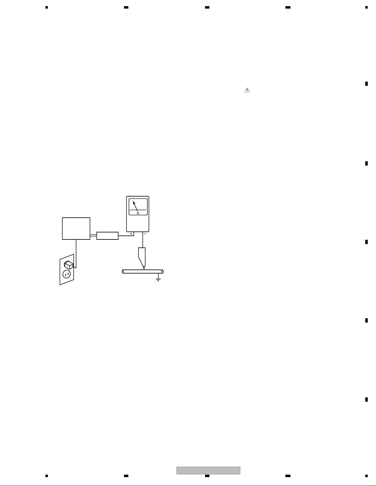
Leakage Current Hot Check
Plug the AC line cord directly into an AC power source (do not
use an isolation transformer for this check).
Turn the AC power switch on.
Using a "Leakage Current Tester (Simpson Model 229
equivalent)", measure for current from all exposed metal parts of
the cabinet (input/output terminals, screwheads, metal overlays,
control shaft, etc.), particularly any exposed metal part having a
return path to the chassis, to a known earth ground (water pipe,
conduit, etc.). Any current measured must not exceed 0.5mA.
Reading should
not be above
0.5mA
Device
under
test
Leakage
current
tester
Test all
exposed metal
surfaces
PRODUCT SAFETY NOTICE
Many electrical and mechanical parts in PIONEER set have
special safety related characteristics. These are often not evident
from visual inspection nor the protection afforded by them
necessarily can be obtained by using replacement components
rated for higher voltage, wattage, etc. Replacement parts which
have these special safety characteristics are identified in this
Service Manual.
Electrical components having such features are identified by
marking with a on the schematics and on the parts list in this
Service Manual.
The use of a substitute replacement component which dose not
have the same safety characteristics as the PIONEER
recommended replacement one, shown in the parts list in this
Service Manual, may create shock, fire or other hazards.
Product Safety is continuously under review and new instructions
are issued from time to time. For the latest information, always
consult the current PIONEER Service Manual. A subscription to,
or additional copies of, PIONEER Service Manual may be
obtained at a nominal charge from PIONEER.
A
B
C
Also test with
plug reversed
(Using AC adapter
plug as required)
Earth
ground
AC Leakage Test
ANY MEASUREMENTS NOT WITHIN THE LIMITS
OUTLINED ABOVE ARE INDICATIVE OF A POTENTIAL
SHOCK HAZARD AND MUST BE CORRECTED BEFORE
RETURNING THE SET TO THE CUSTOMER.
D
E
F
56
PDP-5004
3
7
8
Page 4
1234
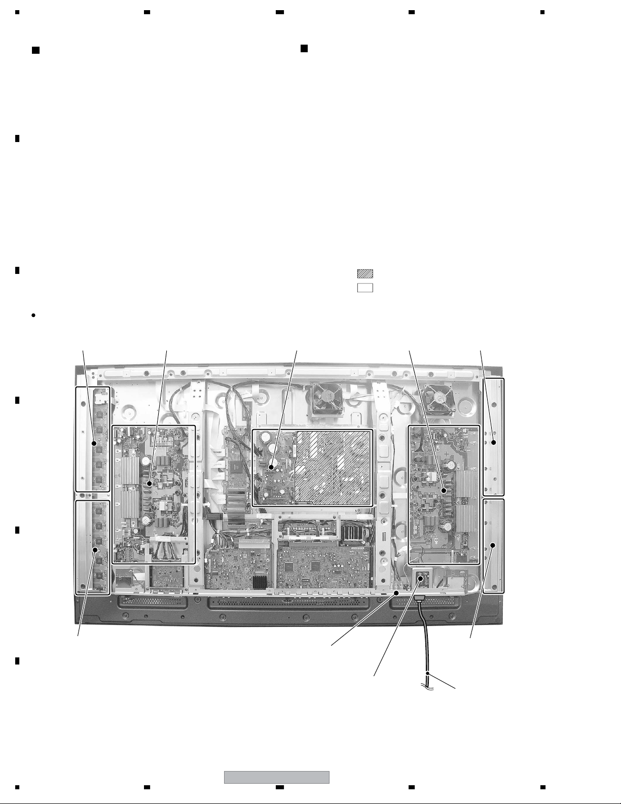
Charged Section
The places where the commercial AC power is used without
A
passing through the power supply transformer.
If the places are touched, there is a risk of electric shock. In
addition, the measuring equipment can be damaged if it is
connected to the GND of the charged section and the GND of the
non-charged section while connecting the set directly to the
commercial AC power supply. Therefore, be sure to connect the
set via an insulated transformer and supply the current.
1. AC Power Cord
2. AC Inlet with Filter
3. Power Switch (S1)
B
4. Fuse (In the POWER SUPPLY Unit)
5. STB Transformer and Converter Transformer
(In the POWER SUPPLY Unit)
6. Other primary side of the POWER SUPPLY Unit
For 50 inch model
(PDP-5004, PDP-5014)
C
50 SCAN B Assy 50 Y DRIVE Assy 50 X DRIVE Assy
High Voltage Generating Point
The places where voltage is 100V or more except for the charged
places described above. If the places are touched, there is a risk of
electric shock.
1. POWER SUPPLY Unit.....................................................(223V)
2. 50 X DRIVE Assy ...........................................(–230V to 223V)
3. 50 Y DRIVE Assy ........................................................... (353V)
4. 50 SCAN A Assy ............................................................ (353V)
5. 50 SCAN B Assy ............................................................(353V)
6. X CONNECTOR A Assy..................................(–230V to 223V)
7. X CONNECTOR B Assy..................................(–230V to 223V)
: Part is Charged Section.
: Part is the High Voltage Generating Points
other than the Charged Section.
POWER SUPPLY Unit
X CONNECTOR
B Assy
D
E
50 SCAN A Assy
F
Fig.1 Charged Section and High Voltage Generating Point (Rear View)
Power Switch
(S1)
AC Inlet with Filter
X CONNECTOR
A Assy
Power Cord
4
1234
PDP-5004
Page 5

5678
Charged Section
The places where the commercial AC power is used without
passing through the power supply transformer.
If the places are touched, there is a risk of electric shock. In
addition, the measuring equipment can be damaged if it is
connected to the GND of the charged section and the GND of the
non-charged section while connecting the set directly to the
commercial AC power supply. Therefore, be sure to connect the
set via an insulated transformer and supply the current.
1. AC Power Cord
2. AC Inlet with Filter
3. Power Switch (S1)
4. Fuse (In the POWER SUPPLY Unit)
5. STB Transformer and Converter Transformer
(In the POWER SUPPLY Unit)
6. Other primary side of the POWER SUPPLY Unit
For 43 inch model
(PDP-4304, PDP-4314)
High Voltage Generating Point
The places where voltage is 100V or more except for the charged
places described above. If the places are touched, there is a risk of
electric shock.
1. POWER SUPPLY Unit................................................... (215V)
2. 43 X DRIVE Assy .......................................... (–225V to 215V)
3. 43 Y DRIVE Assy .......................................................... (345V)
4. 43 SCAN A Assy ............................................................ (345V)
5. 43 SCAN B Assy ............................................................(345V)
6. X CONNECTOR AAssy ................................ (–225V to 215V)
7. X CONNECTOR B Assy ............................... (–225V to 215V)
: Part is Charged Section.
: Part is the High Voltage Generating Points
other than the Charged Section.
A
B
C
43 SCAN B Assy
43 SCAN A Assy
43 Y DRIVE Assy
POWER SUPPLY Unit
Power Switch
(S1)
43 X DRIVE Assy
X CONNECTOR
B Assy
D
E
X CONNECTOR
A Assy
Fig.2 Charged Section and High Voltage Generating Point (Rear View)
PDP-5004
56
AC Inlet with Filter
7
Power Cord
F
5
8
Page 6
1234
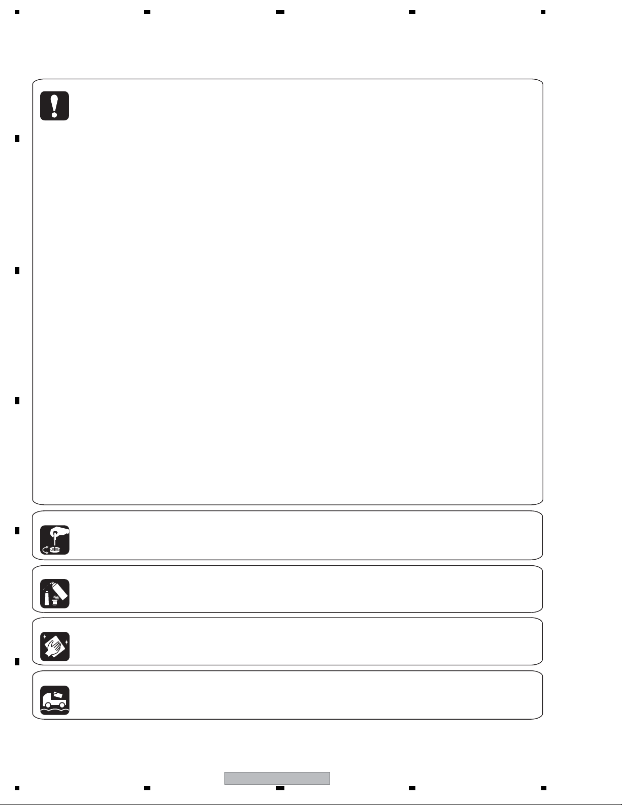
[Important Check Points for Good Servicing]
In this manual, procedures that must be performed during repairs are marked with the below symbol.
Please be sure to confirm and follow these procedures.
A
1. Product safety
Please conform to product regulations (such as safety and radiation regulations), and maintain a safe servicing environment by
following the safety instructions described in this manual.
1 Use specified parts for repair.
Use genuine parts. Be sure to use important parts for safety.
2 Do not perform modifications without proper instructions.
Please follow the specified safety methods when modification(addition/change of parts) is required due to interferences such as
radio/TV interference and foreign noise.
B
C
D
3 Make sure the soldering of repaired locations is properly performed.
When you solder while repairing, please be sure that there are no cold solder and other debris.
Soldering should be finished with the proper quantity. (Refer to the example)
4 Make sure the screws are tightly fastened.
Please be sure that all screws are fastened, and that there are no loose screws.
5 Make sure each connectors are correctly inserted.
Please be sure that all connectors are inserted, and that there are no imperfect insertion.
6 Make sure the wiring cables are set to their original state.
Please replace the wiring and cables to the original state after repairs.
In addition, be sure that there are no pinched wires, etc.
7 Make sure screws and soldering scraps do not remain inside the product.
Please check that neither solder debris nor screws remain inside the product.
8 There should be no semi-broken wires, scratches, melting, etc. on the coating of the power cord.
Damaged power cords may lead to fire accidents, so please be sure that there are no damages.
If you find a damaged power cord, please exchange it with a suitable one.
9 There should be no spark traces or similar marks on the power plug.
When spark traces or similar marks are found on the power supply plug, please check the connection and advise on secure
connections and suitable usage. Please exchange the power cord if necessary.
0 Safe environment should be secured during servicing.
When you perform repairs, please pay attention to static electricity, furniture, household articles, etc. in order to prevent injuries.
Please pay attention to your surroundings and repair safely.
2. Adjustments
To keep the original performance of the products, optimum adjustments and confirmation of characteristics within specification.
Adjustments should be performed in accordance with the procedures/instructions described in this manual.
3. Lubricants, Glues, and Replacement parts
Use grease and adhesives that are equal to the specified substance.
E
Make sure the proper amount is applied.
4. Cleaning
For parts that require cleaning, such as optical pickups, tape deck heads, lenses and mirrors used in projection monitors, proper
cleaning should be performed to restore their performances.
5. Shipping mode and Shipping screws
To protect products from damages or failures during transit, the shipping mode should be set or the shipping screws should be
installed before shipment. Please be sure to follow this method especially if it is specified in this manual.
F
6
1234
PDP-5004
Page 7
5678
COTENTS
SAFETY INFORMATION
1. SPECIFICATIONS
2. EXPLODED VIEWS AND PARTS LIST...........................................................................................................10
2.1 PACKING for PDP-5004, PDP-5014, PDP-4304 and PDP-4314 models.................................................10
2.1.1 PACKING............................................................................................................................................10
2.2 PDP-5004, PDP-5014 models
2.2.1 CHASSIS SECTION (1) .....................................................................................................................12
2.2.2 CHASSIS SECTION (2) .....................................................................................................................14
2.2.3 FRAME SECTION..............................................................................................................................16
2.2.4 TERMINAL PANEL and REAR SECTION ..........................................................................................18
2.2.5 FRONT SECTION..............................................................................................................................20
2.2.6 PANEL CHASSIS (50) ASSY (AWU1099)..........................................................................................22
2.2.7 PDP SERVICE ASSY (AWU1108) .....................................................................................................23
2.3 PDP-4304, PDP-4314 models..................................................................................................................24
2.3.1 CHASSIS SECTION (1) .....................................................................................................................24
2.3.2 CHASSIS SECTION (2) .....................................................................................................................26
2.3.3 FRAME SECTION..............................................................................................................................28
2.3.4 TERMINAL PANEL and REAR SECTION ..........................................................................................30
2.3.5 FRONT SECTION..............................................................................................................................32
2.3.6 PANEL CHASSIS (43) ASSY (AWU1098)..........................................................................................34
2.3.7 PDP SERVICE ASSY (AWU1109) .....................................................................................................35
2.4 MULTI BASE SECTION for PDP-5004, PDP-5014, PDP-4304 and PDP-4314 .......................................36
2.4.1 MULTI BASE SECTION .....................................................................................................................36
3. BLOCK DIAGRAM AND SCHEMATIC DIAGRAM (Refer to “Service Manual: ARP3222”).............................38
3.1 BLOCK DIAGRAM....................................................................................................................................38
3.1.1 OVERALL BLOCK DIAGRAM (1/2) for PDP-5004 and PDP-5014 models
3.1.2 OVERALL BLOCK DIAGRAM (1/2) for PDP-4304, PDP-4314 models
3.1.3 OVERALL BLOCK DIAGRAM (2/2) for PDP-5004, PDP-5014, PDP-4304 and PDP-4314 models...42
3.1.4 SIGNAL ROUTE.................................................................................................................................44
3.1.5 50 Y DRIVE ASSY
3.1.6 43 Y DRIVE ASSY..............................................................................................................................46
3.1.7 50 X DRIVE ASSY .............................................................................................................................47
3.1.8 43 X DRIVE ASSY .............................................................................................................................48
3.1.9 DIGITAL VIDEO ASSY
3.1.10 AV I/O ASSY
3.1.11 RGB ASSY
3.1.12 AUDIO AMP and COMM SLOT ASSYS
3.1.13 VIDEO SLOT 2 ASSY
3.2 WAVEFORMS
3.3 VOLTAGES................................................................................................................................................61
4. PCB CONNECTION DIAGRAM (Refer to “Service Manual: ARP3222”)
5. PCB PARTS LIST
6. ADJUSTMENT ................................................................................................................................................88
6.1 ADJUSTMENT REQUIRED WHEN THE SET IS REPAIRED OR REPLACED........................................88
6.2 SERVICE FACTORY MODE.....................................................................................................................89
6.3 HOW TO ENTER FACTORY MODE.........................................................................................................90
6.4 METHOD FOR REPLACING THE SERVICE PANEL ASSY ..................................................................114
6.5 COMMAND DESCRIPTION ...................................................................................................................115
7. GENERAL INFORMATION ...........................................................................................................................125
7.1 DIAGNOSIS............................................................................................................................................125
7.1.1 CONFIGURATION OF THE PC BOARD
7.1.2 DIAGNOSIS FOR SHUTDOWN AND POWER-DOWN BY LED
7.1.3 PROCESSING AT THE TIME OF ABNORMALITIES.......................................................................133
7.1.4 TEMPERATURE COMPENSATION OF DRIVE SYSTEM VOLTAGE ..............................................133
7.1.5 POWER ON/OFF FUNCTION FOR THE LARGE-SIGNAL SYSTEM..............................................134
7.1.6 BACKUP THE ADJUSTMENT VALUES FOR THE MAIN UNIT.......................................................135
7.1.7 TROUBLESHOOTING......................................................................................................................137
7.1.8 CANCELING DETECTION BY THE TRAP SWITCH .......................................................................139
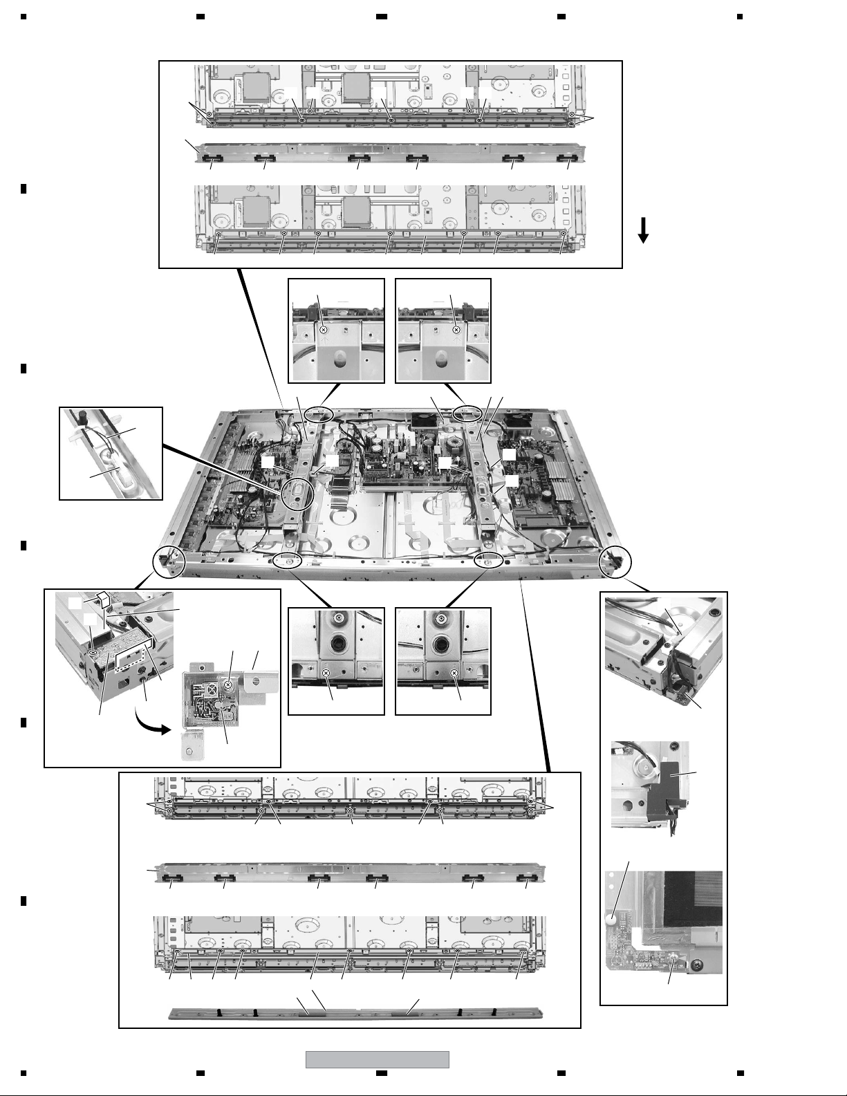
7.1.9 DISASSEMBLY ................................................................................................................................140
7.2 IC INFORMATIION
8. PANEL FACILITIES
12
38
40
45
49
50
51
52
53
54
69
125
126
146
186
2
8
A
B
C
D
E
F
56
PDP-5004
7
7
8
Page 8

1234
1. SPECIFICATIONS
PLASMA DISPLAY
A
General (PDP-5004 /PDP-5014)
Light emission panel .................. 50-inch AC Plasma Panel
109.8 (W) x 62.1 (H) x 126.1 (diagonal) cm
Number of pixels .............................................. 1280 x 768
Power supply ........................................... AC 120 V, 60 Hz
Rated current ............................................................. 3.1 A
Standby power consumption ................................... 0.6 W
External dimensions
.... 1218 (W) x 714 (H) x 98 (D: Not including handles) mm
B
Weight ................................................41.0 kg (90 lbs. 7 oz)
Operating temperature range ........ 0 to 40 °C (32 to 104˚F)
General (PDP-4304/ PDP-4314)
Light emission panel .................. 43-inch AC Plasma Panel
95.2 (W) x 53.6 (H) x 109.3 (diagonal) cm
Number of pixels .............................................. 1024 x 768
Power supply ........................................... AC 120 V, 60 Hz
Rated current ............................................................. 2.6 A
C
Standby power consumption ................................... 0.6 W
External dimensions
.... 1070 (W) x 630 (H) x 98 (D: Not including handles) mm
Weight ............................................. 33.5 kg (73 lbs. 14 oz)
Operating temperature range ........ 0 to 40 °C (32 to 104˚F)
Input/output
Video
D
INPUT1
Input Mini D-sub 15 pin (socket connector)
• RGB signal (G ON SYNC compatible)
RGB ... 0.7 Vp-p/75 /no sync.
HD/CS, VD ... TTL level
G ON SYNC
*Compatible with Microsoft Plug & Play
E
(VESA DDC1/2B)
• Component video signal
Y ... 1 Vp-p/75 negative sync.
B/PB, CR/PR ... 0.7 Vp-p (color100%)/75
C
47-31/32 (W) x 28-1/8 (H) x 3-7/8
(D: Not including handles) in.
42-1/8 (W) x 24-13/16 (H) x 3-7/8
(D: Not including handles) in.
Ω
/positive and negative polarity
Ω
/2.2 k
... 1 Vp-p/75 /negative sync.
Ω
Ω
INPUT2
Input HDMI
• Digital signal
3.3V T.M.D.S. /50
INPUT3
Input S jack (Mini DIN 4 pin)
• Y/C separate video signal
Y . . . 1 Vp-p/75 /negative sync.
0.286 Vp-p/75
C . . .
(Color Burst Level)
INPUT4
Input RCA jack
• Composite video signal
1 Vp-p/75 /negative sync.
Output RCA jack
75 /with buffer
INPUT5
Input RCA jack
• Component video signal
Y…1 Vp-p /75 negative sync.
B/PB, CR/PR…
C
• RGB signal
G ON SYNC ...
R/B ... 0.7 Vp-p/75 /no sync.
Audio
Input AUDIO INPUT (for INPUT1)
Pin jack (x2)
L/R ... 500 mVrms/more than 10 k
AUDIO INPUT (for INPUT2)
Pin jack (x2)
L/R ... 500 mVrms/more than 10 k
AUDIO INPUT (for INPUT3)
Pin jack (x2)
L/R ... 500mVrms/more than 10 k
AUDIO INPUT (for INPUT4)
Pin jack (x2)
L/R ... 500mVrms/more than 10 k
AUDIO INPUT (for INPUT5)
Pin jack (x2)
L/R ... 500mVrms/more than 10 k
Ω
Output SPEAKER
L/R ... 8 – 16 /7 W +7 W (at 8 )
Ω
Ω
0.7 Vp-p (color 100%) / 75
1 Vp-p/75 /negative sync.
Ω
Ω
Ω
Ω
Ω
Ω
Ω
Ω
Ω
Ω
Ω
Ω
ΩΩ
Control
RS-232C... D-sub 9 pin (pin connector)
F
8
1234
PDP-5004
Page 9

5678
Accessories
Power Cord (ADG1215)
A
Remote Control Unit for PDP-5004, PDP-4304
(AXD1496)
B
Cleaning Cloth (for wiping front panel)
(AED1208)
Binder Assy (AEC1758)
Speed Clamp (×2)
Bead Bands (×2)
Remote Control Unit for PDP-5014, PDP-4314
(AXD1497)
C
Dry Cell Battery (R6P, AA)
D
56
PDP-5004
E
F
9
7
8
Page 10

1234
2. EXPLODED VIEWS AND PARTS LIST
NOTES:
A
Parts marked by "NSP" are generally unavailable because they are not in our Master Spare Parts List.
The mark found on some component parts indicates the importance of the safety factor of the part.
Therefore, when replacing, be sure to use parts of identical designation.
Screws adjacent to mark on product are used for disassembly.
For the applying amount of lubricants or glue, follow the instructions in this manual.
(In the case of no amount instructions, apply as you think it appropriate.)
2.1 PACKING for PDP-5004, PDP-5014, PDP-4304 and PDP-4314 models
2.1.1 PACKING
21
B
14
C
20
12
15 (for PDP-5004, PDP-5014)
16 (for PDP-4304, PDP-4314)
D
E
18
11
19
15 (for PDP-5004, PDP-5014)
17 (for PDP-4304, PDP-4314)
1
8, 9, 10, 13
7
2
4
3
5
6
F
10
1234
20
PDP-5004
Page 11
5678
PACKING Parts List
No. Description Part No.
No. Description Part No.
Mark
1Power Cord ADG1215
2 Remote Control Unit See Contrast table (2)
3 Battery Cover AZN2462
NSP 4 Dry Cell Battery (R6P, AA) AEX1026
5 Wiping Cloth (for screen) AED1208
6 Binder Assy AEC1758
(Speed Clamp x2, Bead Band x2)
7 Operating Instructions ARE1386
(English / French / Spanish)
8 Plasma Caution Sheet ARM1145
9 Caution Sheet ARM1176
10 Caution Sheet ARM1194
11 Caution Sheet ARM1201
NSP 12 Warranty Card ARY1138
NSP 13 Card VRY1132
Mark
14 Vinyl Bag AHG1310
15 Pad See Contrast table (2)
16 Pad (43U) See Contrast table (2)
17 Pad (43L) See Contrast table (2)
18 Mirror Mat AHG1284
19 Accessory Case AHC1036
20 Under Carton See Contrast table (2)
21 Upper Carton See Contrast table (2)
(2) CONTRAST TABLE
PDP-5004/KUC, PDP-5014/KUC, PDP-4304/KUC and PDP-4314/KUC are constructed the same except for the following:
Mark No. Symbol and Description
2 Remote Control Unit AXD1496 AXD1497 AXD1496 AXD1497
PDP-5004/
KUC
PDP-5014/
KUC
PDP-4304/
KUC
PDP-4314/
KUC
A
B
C
15 Pad AHA2280 AHA2280 Not used Not used
16 Pad (43U) Not used Not used
17 Pad (43L) Not used Not used
20 Under Carton AHD3037 AHD3037
21 Upper Carton AHD3286 AHD3288 AHD3287 AHD3289
AHA2282 AHA2282
AHA2283 AHA2283
AHD3100 AHD3100
D
E
56
PDP-5004
>
F
11
7
8
Page 12
1234
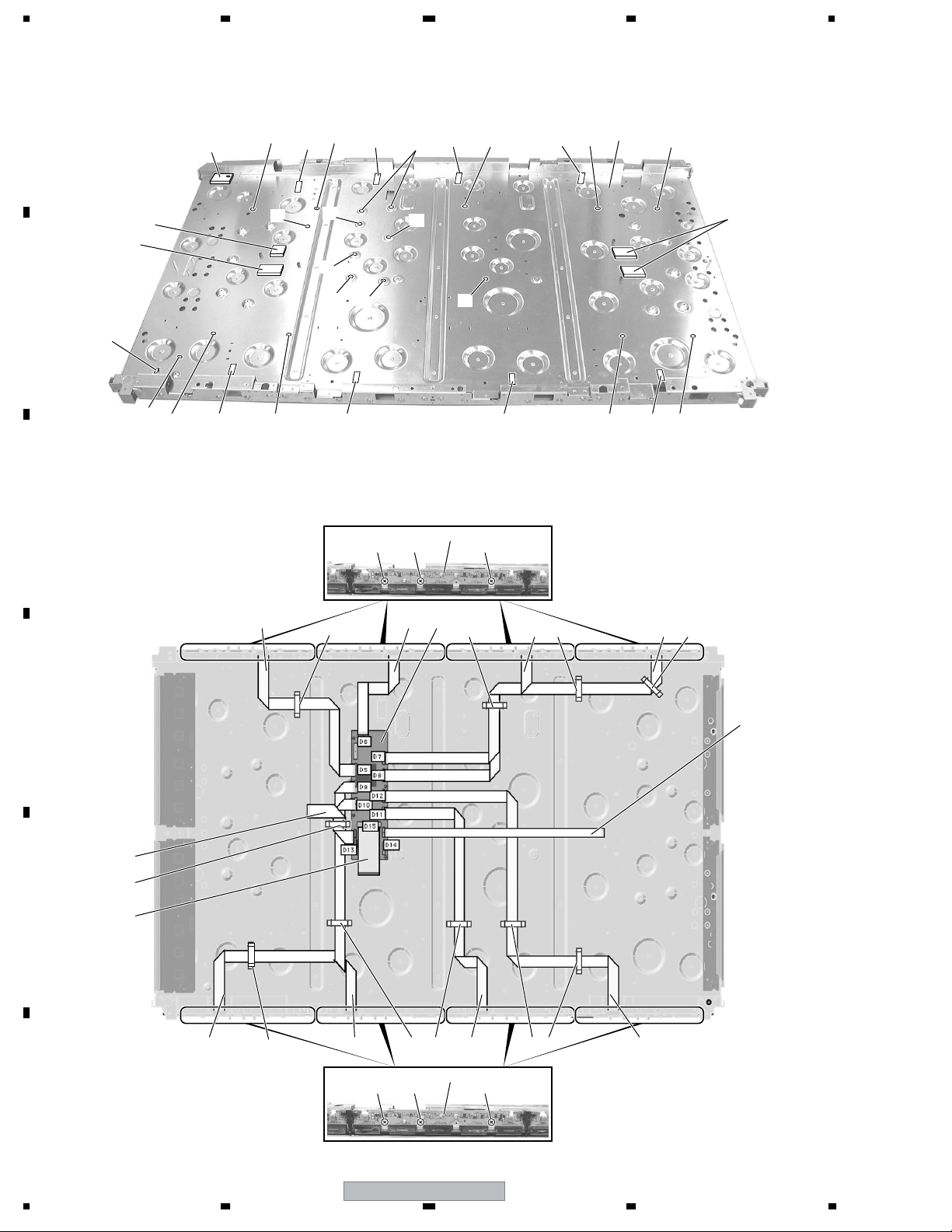
2.2 PDP-5004, PDP-5014 models
2.2.1 CHASSIS SECTION (1)
A
15
25
17
15
17
15
17 18
24
15
1
15
15
16
15
14
15
15
22 22 22
2
23 3
18
1717
6 14 1414 7
17
21
15
20
21
B
19
18
C
17 151515
16
5
D
8
14
E
F
4
10
14
11 14 14
22 22 22
12
2
1414
13
9
12
PDP-5004
1234
Page 13

5678
CHASSIS SECTION (1) parts List
No. Description Part No.
Mark
NSP 1 P. Chassis (50) Assy AWU1099
NSP 2 50 ADDRESS Assy AWZ6839
3 DIGITAL VIDEO Assy AWV2100
4 FPC (114P) ADY1081
5 Flexible Cable (J201) ADD1248
6 Flexible Cable (J203) ADD1250
7 Flexible Cable (J204) ADD1251
8 Flexible Cable (J209) ADD1236
9 Flexible Cable (J210) ADD1237
10 Flexible Cable (J205) ADD1252
11 Flexible Cable (J206) ADD1253
12 Flexible Cable (J207) ADD1254
13 Flexible Cable (J208) ADD1255
14 Flat Clamp AEC1879
No. Description Part No.
Mark
15 PCB Spacer AEC1941
16 PCB Support AEC1938
17 Wire Saddle AEC1745
18 PCB Spacer AEC1947
19 Locking Wire Saddle AEC1948
20 Drive Silicone Sheet C AEH1066
21 Drive Silicone Sheet B AEH1065
22 Screw VBB30P080FNI
23 Flexible Cable (J202) ADD1249
24 Locking Wire Saddle AEC1992
25 SCAN Silicone Sheet AEH1080
A
B
C
D
E
56
PDP-5004
F
13
7
8
Page 14

1234
2.2.2 CHASSIS SECTION (2)
A
19
9
20
B
17
13
C
23
25
22
8
20
3
15
15
100V
15
15
15
24
15 14
15
19
10
15
15
15
D
17
16
E
21
21
Upper
F
side
16
7
11
16
26 2827
17
2
17
16
6
16
16
21
21
12
21
21
18
17
21
18
17
1
16
45
21
21
Upper
side
18
17
21
14
PDP-5004
1234
Page 15

5678
CHASSIS SECTION (2) parts List
Mark No. Description Part No.
1 50 X DRIVE Assy AWZ6959
2 50 Y DRIVE Assy AWV2144
> 3POWER SUPPLY Unit AXY1083
NSP 4 X CONNECTOR B Assy AWZ6812
NSP 5 X CONNECTOR A Assy AWZ6811
NSP 6 50 SCAN A Assy AWZ6809
NSP 7 50 SCAN B Assy AWZ6810
8PANEL SENSOR Assy AWZ6795
9Fan Motor (80 x 25) AXM1044
10 Fan Angle (504) ANG2609
11 Front Chassis VL (50M) ANA1753
12 Front Chassis VR (50M) ANA1754
13 SCAN Heatsink ANH1630
14 Housing Wire (J117) ADX2897
15 Screw ABZ30P060FMC
16 Screw PMB30P060FNI
17 Screw VBB30P080FNI
18 Screw PMB40P080FZK
19 Screw PPZ50P100FZK
20 Nylon Rivet AEC1671
21 Screw AMZ30P060FZK
22 3P Housing Wire (J109) ADX2847
23 11P Housing Wire (J102) ADX2853
24 12P Housing Wire (J103) ADX2854
25 Wire A (J101) ADX2839
26 WireD (J118) ADX3030
27 5P Housing Wire (J119) ADX3031
28 9P Housing Wire (J115) ADX2895
A
B
C
D
56
PDP-5004
E
F
15
7
8
Page 16
1234
2.2.3 FRAME SECTION
A
B
C
24
17
6
7 7 7 7 7 7
17
25
11
1618 1618
17
17 17 8 17 17 17
16
9 954
11
10
18
17
Upper
side
16
11
11
22
19
D
2
E
F
17
6
• Rear view
13
23
17
14
12
19
16
1
1616
7
7 7 7 7 7
26
17 17 17 17 17 17
8
27 27
16
17
181818
14
3
15
20
21
16
PDP-5004
1234
Page 17

5678
FRAME SECTION parts List
Mark No. Description Part No.
1 IR RECEIVE Assy AWZ6855
2 KEY CONTROL Assy AWZ6969
3 LED Assy AWZ6966
4 Sub Frame L Assy (50M) ANG2596
5 Sub Frame R Assy (50M) ANG2598
6Front Chassis H (50) ANA1733
7Front Spacer (CMX) AMR3384
8 Rear Frame (50M) ANG2602
9 Locking Wire Saddle AEC1948
10 Locking Wire Saddle AEC1992
11 Wire Saddle AEC1745
NSP 12 IR Holder ANG2551
13 Nylon Rivet AEC1671
14 Flat Clamp AEC1879
15 Enclosure Sheet 1 AMR3405
16 Screw AMZ30P080FMC
17 Screw AMZ30P060FZK
18 Screw APZ30P080FZK
19 Screw ABZ30P060FMC
20 Nylon Rivet AEC1997
21 Screw BBZ30P050FMC
22 Enclosure Sheet 2 (V) AMR3411
23 Enclosure Sheet 3 AMR3407
24 Power Switch (S2)(TRAP) ASG1089
25 3P Housing Wire (J114) ADX3032
26 Gasket S (CM) ANK1749
27 Gasket (CM) ANK1748
A
B
C
D
E
F
56
PDP-5004
17
7
8
Page 18

1234
2.2.4 TERMINAL PANEL and REAR SECTION
28
(1/4)
A
36
30
18
18
18
26
29
18 18
36
(2/4)
30
18
18
18
18
39
18
31
36
32
32
30
30
(4/4)
32
31
32
30
B
30
36
(3/4)
C
18
6 6
27
18
24
18
23
18 18
33
17
9
8
18
18
18
18
34 35
1
17
8
18
8
30
4
25
18
18
38
11
7
2 38
15
16
18
18
18
20
17
17
40
38
D
E
Rear view
F
37
38
18
14 14
13 13 11
18
21
18
3
22
18
18
5
25
30
10
18
PDP-5004
1234
Page 19

5678
TERMINAL PANEL and REAR SECTION parts List
Mark No. Description Part No.
1 COMM SLOT I/F Assy AWZ6964
2 COMM SLOT Assy AWZ6968
> 3AC Inlet (CN1) AKP1244
4 SP TERMINAL R Assy AWZ6857
5 SP TERMINAL L Assy AWZ6856
6 Guide Rail EX AEC1994
7 6P Housing Wire (J108) ADX3029
8 Wire Saddle AEC1745
9 Clamp AEC1884
10 Terminal Panel (F50) ANG2685
11 Gasket SP-T ANK1734
12 • • • • •
13 Slot Spring B126 ABK1033
14 Slot Spring T130 ABK1032
15 Slot Spring T94 ABK1034
16 Slot Spring B92 ABK1035
17 Screw VBB30P080FNI
18 Screw AMZ30P060FZK
19 • • • • •
20 Hexagon Head Screw BBA1051
Mark No. Description Part No.
> 21 Power Switch (S1) ASG1094
22 Housing Wire (MX)(J116) ADX2896
23 COMM Stay A ANG2605
24 COMM Stay B ANG2606
25 Screw APZ30P080FZK
26 Rear Case (50M) ANE1623
27 Gasket T-R50 ANK1735
NSP 28 Name Label See Contrast table (2)
29 Caution Label AAX3048
30 Screw TBZ40P080FZK
31 Grip AMR3380
32 Screw HMB50P140FZK
33 Terminal Label R (SF50C) AAX3126
34 Terminal Label C (SF50C) AAX3130
35 Terminal Label V (CM) AAX3137
36 Rear Corner Label (15) AAX3081
37 VIDEO SLOT 2 Assy AWV2159
38 Screw ABA1300
39 Terminal Label L (50M) AAX3061
40 Screw BMZ30P080FZK
A
B
C
(2) CONTRAST TABLE
PDP-5004/KUC and PDP-5014/KUC are constructed the same except for the following:
Mark No. Symbol and Description
NSP 28 Name Label (SF50C) AAL2593 Not used
NSP 28 Name Label (SF50S) Not used AAL2595
PDP-5004/
KUC
PDP-5014/
KUC
D
E
56
PDP-5004
F
19
7
8
Page 20
1234
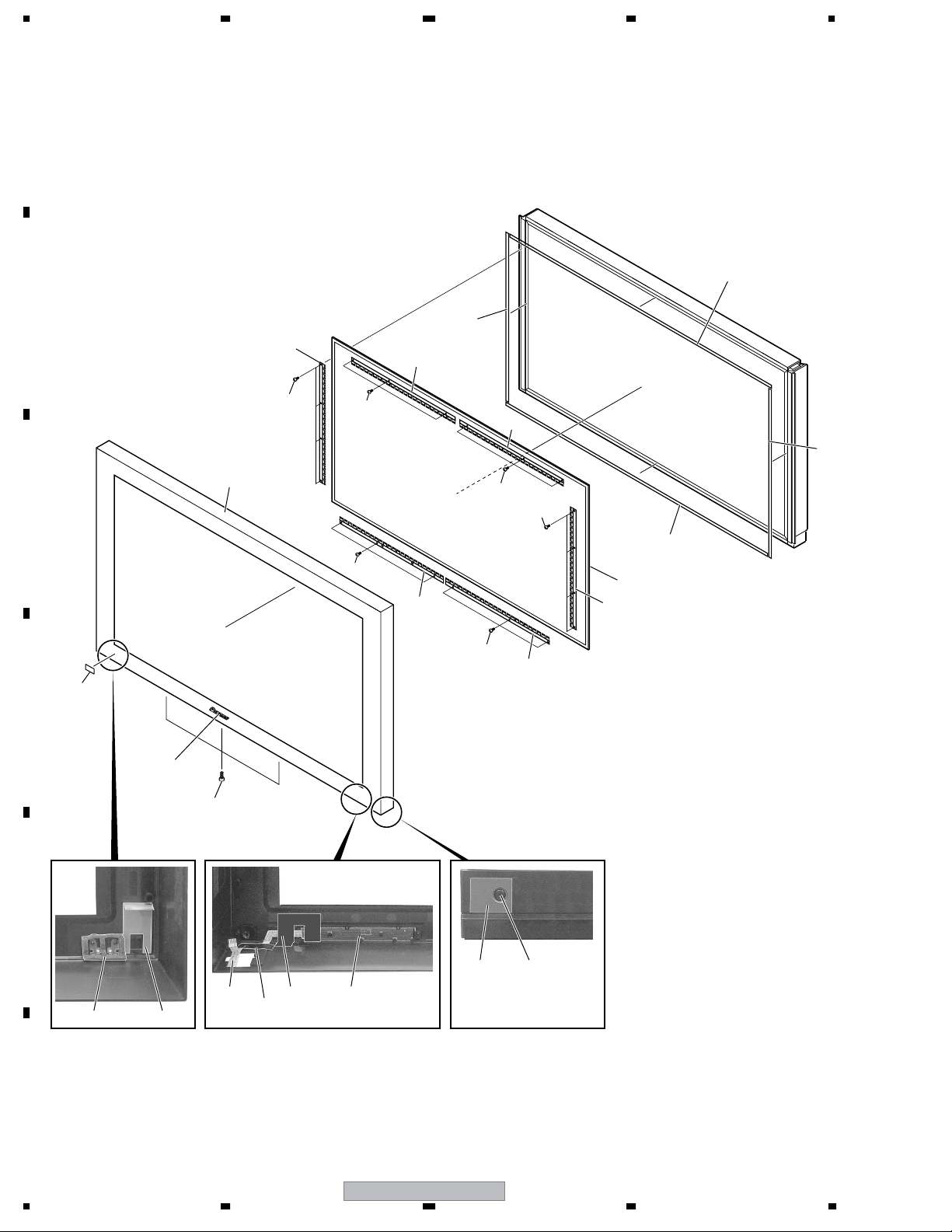
2.2.5 FRONT SECTION
A
4
B
6
13
8
C
9
D
14
14
6
6
3
6
3
14
13
4
5
6
14
6
2
15
E
16 17
11 12
10 7
F
18
20
1234
1
PDP-5004
Page 21
5678
FRONT SECTION parts List
Mark No. Description Part No.
1FRONT KEY Assy AWZ6970
2 PIONEER Badge AAM1091
3Panel Cushion V AED1199
4Panel Cushion H AED1226
> 5 Protect Panel Assy (50) AMR3348
6Panel Holder (50) ANG2563
7 Earth Plate (MX) AMR3432
8Front Case Assy See Contrast table (2)
NSP 9 Energy Star Label AAX8022
10 Blind Cushion AEB1400
Mark No. Description Part No.
11 Flexible Cable (J211) ADD1281
12 Flexible Seal (P) AEH1072
13 Screw ABZ30P060FMC
14 Screw APZ30P080FZK
15 Screw APZ30P120FZK
16 Lead Cover See Contrast table (2)
17 Rivet AEC1877
18 Flexible Seal (SF) AEH1082
(2) CONTRAST TABLE
PDP-5004/KUC and PDP-5014/KUC are constructed the same except for the following:
Mark No. Symbol and Description
8Front Case Assy (F50C) AMB2843 Not used
8Front Case Assy (F50S) Not used AMB2844
16 Lead Cover (SF) AMR3436 Not used
16 Lead Cover (4G) Not used AMR3395
PDP-5004/
KUC
PDP-5014/
KUC
A
B
C
D
E
56
PDP-5004
F
21
7
8
Page 22

1234
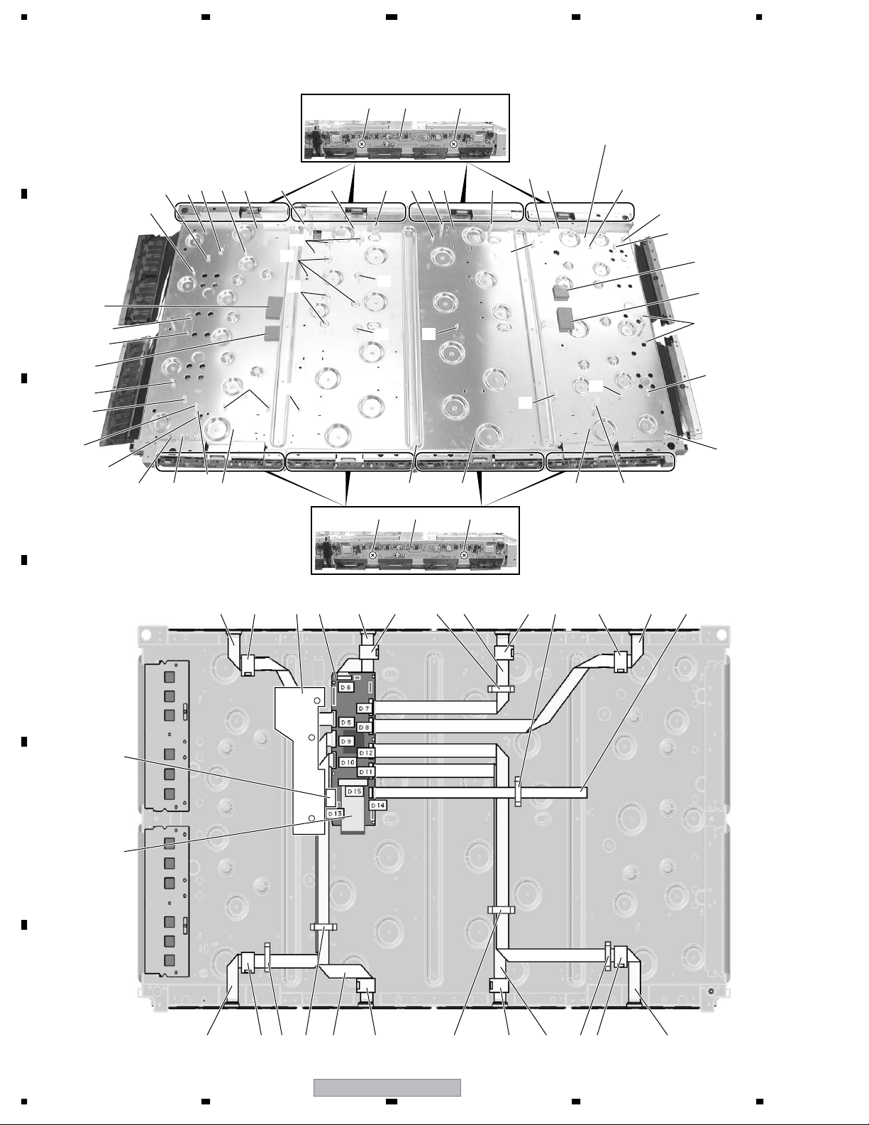
2.2.6 PANEL CHASSIS (50) ASSY (AWU1099)
Panel Chassis (50) Assy (AWU1099)
No. Description Part No.
Mark
A
NSP 1..50 ADDRESS Assy AWV2121
NSP 2..50 ADDRESS Assy AWZ6839
NSP 1..50 SCAN FUKUGO Assy AWV2036
NSP 2..50 SCAN A Assy AWZ6809
NSP 2..50 SCAN B Assy AWZ6810
NSP 2..X CONNECTOR A Assy AWZ6811
NSP 2..X CONNECTOR B Assy AWZ6812
NSP Address Module (IC1-IC40) AXF1124
NSP Plasma Panel Assy (50")(V1) AAV1251
B
NSP FPC (50XGA-X) ADY1084
NSP FPC (50XGA-Y) ADY1085
NSP Chassis Assy (50) ANA1774
Edge Card Spacer AEC1998
PCB Spacer AEC1944
PCB Support AEC1958
Rivet AMR1066
FC Spacer AMR3370
NSP Adhesive ZBA-KE3424S
C
NSP Cleaner ZLX-AP7
NSP Tape ZTA-8101-12
NSP Double Faced Tape ZTB-5015-18
NSP Tape ZTC-POLYCA-11
NSP Tape ZTC-POLYCA-20
NSP Double Faced Tape ZTB-5015-9
NSP Tape ZTC-900UL-15
NSP Silicone Rubber ZTX-HC20-15
NSP Wiping Cloth ZTX-MX100-13
D
NSP Film ZTX-2102Y35-2R5
NSP Film ZTX-2102Y45-5
NSP Silicone Rubber ZTX-HC50-15
NSP Silicone Rubber
ZTC-EM7KBOR85T-15W
E
F
22
1234
PDP-5004
Page 23

5678
2.2.7 PDP SERVICE ASSY (AWU1108)
PDP SERVICE Assy (AWU1108)
No. Description Part No.
Mark
NSP P. Chassis (50) Assy AWU1099
NSP Front Chassis H (50) ANA1733
F. Chassis VL (50M) ANA1765
F. Chassis VR (50M) ANA1766
Sub Frame R Assy (50M) ANG2561
Spacer AEB1397
Wire Saddle AEC1745
Clamp AEC1884
PCB Support AEC1938
PCB Spacer AEC1941
PCB Spacer AEC1947
Wire Clip AEC1948
Wire Clip AEC1992
Panel Cushion V AED1199
Panel Cushion H AED1226
Siricon Sheet SC AEH1080
Front Spacer AMR3369
Caution Label AAX3031
NSP Drive Voltage Label ARW1097
Screw ABZ30P100FZK
Screw AMZ30P080FMC
Screw APZ30P080FZK
NSP Front Case (504 SVC) AMB2811
Rear Case (50P) ARM1247
Caution Card (SVC) AHA2280
Pad (PP T-L) AHA2315
Pad (PP T-R) AHA2316
Center Pad (50) AHA2335
Pad (PP B-L) AHA2343
Pad (PP B-R) AHA2344
NSP Upper Carton (504SVC) AHD3212
Sub Frame L Assy (50M) ANG2638
Scan Heatsink ANH1630
Screw AMZ30P060FZK
Sub Carton AHB1248
Carton (50) AHD3177
Protect Sheet AHG1331
A
B
C
D
E
56
PDP-5004
F
23
7
8
Page 24
1234
2.3 PDP-4304, PDP-4314 models
2.3.1 CHASSIS SECTION (1)
A
17 16
19
31
18
B
25
31
31
24
18
19
17
C
22
31
23
20 21 21 21 21
17
16
17
30
20
20 2022 20
16
16
2
27 27
29
16
16
16
27 27
22
16
21 20 20 21
2
1
16
18
17
24
25
18
17
16
18
5
14 1428 14 146 7 915 1526 3
D
8
E
4
F
24
14
14 14 12 13141115 15 15 1510
PDP-5004
1234
Page 25

5678
CHASSIS SECTION (1) parts List
No. Description Part No.
Mark
NSP 1 P. Chassis (43) Assy AWU1098
NSP 2 43 ADDRESS Assy AWZ6793
3 DIGITAL VIDEO Assy AWV2100
4 FPC (114P) ADY1081
5 Flexible Cable (J201) ADD1257
6 Flexible Cable (J203) ADD1259
7 Flexible Cable (J204) ADD1260
8 Flexible Cable (J209) ADD1223
9 Flexible Cable (J210) ADD1224
10 Flexible Cable (J205) ADD1261
11 Flexible Cable (J206) ADD1262
12 Flexible Cable (J207) ADD1263
13 Flexible Cable (J208) ADD1264
14 Ferrite Core ATX1048
15 Flat Clamp AEC1879
16 PCB Spacer AEC1941
17 PCB Support AEC1938
18 PCB Spacer AEC1944
19 PCB Support AEC1958
20 Ferrite Clamp AEC1986
21 Wire Saddle AEC1745
22 PCB Spacer AEC1947
23 Locking Wire Saddle AEC1948
24 Drive Silicone Sheet C AEH1066
25 Drive Silicone Sheet B AEH1065
26 Y Drive Protection Sheet AMR3346
27 Screw VBB30P080FNI
28 Flexible Cable (J202) ADD1258
29 Locking Wire Saddle AEC1992
30 Harness Lifter 18 AEC1980
31 Edge Card Spacer AEC1998
A
B
C
D
56
PDP-5004
E
F
25
7
8
Page 26

1234
2.3.2 CHASSIS SECTION (2)
20
A
8
100V
14
19
19
9
Upper
side
32
15
11
19
15
15
19
B
C
32
10
Upper
side
15
9
2627
20
31
29 30
23
15
28
3
152225
31
1524
15
15
15
D
31
17
16
E
21
21
Upper
F
side
7 6
18
17
21
12
17
16
2
21
21 21 21
21
31
16
17
18 18
17
21
13
1
17
16
45
21
Upper
side
26
PDP-5004
1234
Page 27

5678
CHASSIS SECTION (2) parts List
No. Description Part No.
Mark
>
1 43 X DRIVE Assy AWZ6840
2 43 Y DRIVE Assy AWV2022
3POWER SUPPLY Unit AXY1083
NSP 4 X CONNECTOR B Assy AWZ6799
NSP 5 X CONNECTOR A Assy AWZ6798
NSP 6 43 SCAN A Assy AWZ6796
NSP 7 43 SCAN B Assy AWZ6797
8PANEL SENSOR Assy AWZ6795
9Fan Motor (80 x 25) AXM1044
10 Fan Angle L (43M) ANG2655
11 Fan Angle R (43M) ANG2656
12 Front Chassis VL (43M) ANA1755
13 Front Chassis VR (43M) ANA1756
14 Housing Wire for Fan (J117) ADX2904
15 Screw ABZ30P060FMC
16 Screw PMB30P060FNI
17 Screw VBB30P080FNI
18 Screw PMB40P080FZK
19 Screw PPZ50P100FZK
20 Nyron Rivet AEC1671
21 Screw AMZ30P060FZK
22 3P Housing Wire (J109) ADX2847
23 11P Housing Wire (J102) ADX2840
24 12P Housing Wire (J103) ADX2841
25 Wire A (J101) ADX2839
26 Wire G (J118) ADX3034
27 5P Housing Wire (J119) ADX3035
28 9P Housing Wire (J115) ADX2902
29 Sub Frame L Assy (43M) ANG2623
30 Sub Frame R Assy (43M) ANG2625
31 Screw AMZ30P080FMC
32 Locking Wire Saddle AEC1948
>
A
B
C
D
56
PDP-5004
E
F
27
7
8
Page 28
1234
2.3.3 FRAME SECTION
A
B
C
5
17
7 7 7
24
17
4
16
18
6
17
8
25
10
18
17
16
18
17 17
9
10
11
7 77
11
17
24
Rear view
Upper
side
15
26
D
E
22
19
2
17
24
14
19
23
13
16
6
12
20
16
7 77777
21
17
24
Rear view
14
3
F
28
1234
1
PDP-5004
Page 29

5678
FRAME SECTION parts List
No. Description Part No.
Mark
1 IR RECEIVE Assy AWZ6855
2 KEY CONTROL Assy AWZ6969
3 LED Assy AWZ6966
4Power Switch (S2)(TRAP) ASG1089
5 3P Housing Wire (J114) ADX3036
6Front Chassis H (43) ANA1714
7Front Spacer (CMX) AMR3384
8 Rear Frame (43M) ANG2613
9 Locking Wire Saddle AEC1948
10 Locking Wire Saddle AEC1992
11 Wire Saddle AEC1745
NSP 12 IR Holder ANG2551
13 Nyron Rivet AEC1671
14 Flat Clamp AEC1879
15 Enclosure Sheet 1 AMR3405
16 Screw AMZ30P080FMC
17 Screw AMZ30P060FZK
18 Screw APZ30P080FZK
19 Screw ABZ30P060FMC
20 Nyron Rivet AEC1997
21 Screw BBZ30P050FMC
22 Enclosure Sheet 2 (V) AMR3411
23 Enclosure Sheet 3 AMR3407
24 Screw PMB30P060FNI
25 Cable Cover AMR3431
NSP 26 Front Case Spacer AMR3430
A
B
C
D
E
F
56
PDP-5004
29
7
8
Page 30

1234
2.3.4 TERMINAL PANEL and REAR SECTION
18
A
36
(1/4)
30
28
18
26
18
29
18
36
(2/4)
30
18
18
18
18
12
18
36
32
31
30
32
30
(4/4)
18
32
30
31
18
32
36
6 6
30
(3/4)
18
27
24
23
18
33
18
8
B
C
17
18
18
18
18
34 35
1
17
9
8
18
5
25
30
37373737
10
11
21
18
3
18
4
30
25
18
8
2 39
39
11
15
7
16
18
17
17
19
20
18 18
1818
39
18
38
13 13
14
14
39
18
D
E
Rear view
F
22
30
PDP-5004
1234
Page 31

5678
TERMINAL PANEL and REAR SECTION parts List
No. Description Part No.
Mark
>
>
1 COMM SLOT I/F Assy AWZ6964
2 COMM SLOT Assy AWZ6968
3AC Inlet (CN1) AKP1244
4 SP TERMINAL R Assy AWZ6857
5 SP TERMINAL L Assy AWZ6856
6 Guide Rail EX AEC1994
7 6P Housing Wire (J108) ADX3033
8 Wire Saddle AEC1745
9 Clamp AEC1884
10 Terminal Panel (F43) ANG2687
11 Gasket SP-T ANK1734
12 Terminal Label L (43M) AAX3062
13 Slot Spring B126 ABK1033
14 Slot Spring T130 ABK1032
15 Slot Spring T94 ABK1034
16 Slot Spring B92 ABK1035
17 Screw VBB30P080FNI
18 Screw AMZ30P060FZK
19 Screw BMZ30P080FZK
20 Hexagon Head Screw BBA1051
No. Description Part No.
Mark
21 Power Switch (S1) ASG1094
22 Housing Wire (MX)(J116) ADX2896
23 COMM Stay A ANG2605
24 COMM Stay B ANG2606
25 Screw APZ30P080FZK
26 Rear Case (43M) ANE1624
27 Gasket T-R43 ANK1736
NSP 28 Name Label See Contrast table (2)
29 Caution Label (M) AAX3048
30 Screw TBZ40P080FZK
31 Grip AMR3380
32 Screw HMB50P140FZK
33 Terminal Label R (SF43C) AAX3128
34 Terminal Label C (SF43C) AAX3130
35 Terminal Label V (CM) AAX3137
36 Rear Corner Label (15) AAX3081
37 Spacer AMR3433
38 VIDEO SLOT 2 Assy AWV2159
39 Screw ABA1300
A
B
C
(2) CONTRAST TABLE
PDP-4304/KUC and PDP-4314/KUC are constructed the same except for the following:
Mark No. Symbol and Description
NSP 28 Name Label (SF43C) AAL2594 Not used
NSP 28 Name Label (SF43S) Not used AAL2596
PDP-4304/
KUC
PDP-4314/
KUC
D
E
56
PDP-5004
F
31
7
8
Page 32

1234
2.3.5 FRONT SECTION
A
4
B
6
6
13
14
8
C
14
6
9
D
2
3
6
3
14
13
4
5
6
14
6
15
E
16 17
11 12
10 18
F
7
32
1234
1
PDP-5004
Page 33

5678
FRONT SECTION (1) parts List
No. Description Part No.
No. Description Part No.
Mark
>
1FRONT KEY Assy AWZ6970
2 Pioneer Name Plate AAM1091
3Panel Cushion V (43M) AED1254
4Panel Cushion H (43M) AED1253
5 Protect Panel Assy (43) AMR3345
NSP 6 Panel Holder (43) ANG2552
7 Flexible Seal (SF) AEH1082
8Front Case Assy See Contrast table (2)
9 Energy Star Label AAX8022
10 Blind Cushion AEB1400
Mark
11 Flexible Cable (J211) ADD1281
12 Flexible Seal (P) AEH1072
13 Screw ABZ30P060FMC
14 Screw APZ30P080FZK
15 Screw APZ30P120FZK
16 Lead Cover See Contrast table (2)
17 Rivet AEC1877
18 Earth Plate (MX) AMR3432
(2) CONTRAST TABLE
PDP-4304/KUC and PDP-4314/KUC are constructed the same except for the following:
Mark No. Symbol and Description
8Front Case Assy (F43C) AMB2846 Not used
8Front Case Assy (F43S) Not used AMB2847
16 Lead Cover (SF) AMR3436 Not used
16 Lead Cover (4G) Not used AMR3395
PDP-4304/
KUC
PDP-4314/
KUC
A
B
C
D
E
56
PDP-5004
F
33
7
8
Page 34

1234
2.3.6 PANEL CHASSIS (43) ASSY (AWU1098)
Panel Chassis (43) Assy (AWU1098)
• Parts List
Mark
A
B
C
D
No. Description Part No.
NSP 1..43 ADDRESS Assy AWV2120
NSP 2..43 ADDRESS Assy AWZ6793
NSP 1..43 SCAN FUKUGO Assy AWV2023
NSP 2..43 SCAN A Assy AWZ6796
NSP 2..43 SCAN B Assy AWZ6797
NSP 2..X CONNECTOR A Assy AWZ6798
NSP 2..X CONNECTOR B Assy AWZ6799
NSP Address Module (IC1-IC32) AXF1124
NSP Plasma Panel Assy (43")(V1) AAV1250
NSP FPC (43XGA-X) ADY1079
NSP FPC (43XGA-Y) ADY1080
NSP Chassis Assy (43) ANA1773
PCB Spacer AEC1944
PCB Support AEC1958
Edge Card Spacer AEC1998
Rivet AMR1066
FC Spacer AMR3370
NSP Adhesive ZBA-KE3424S
NSP Cleaner ZLX-AP7
NSP Tape ZTA-8101-12
NSP Double Faced Tape ZTB-5015-18
NSP Double Faced Tape ZTB-5015-9
NSP Tape ZTC-POLYCA-11
NSP Tape ZTC-POLYCA-20
NSP Tape ZTC-900UL-15
NSP Wiping Cloth ZTX-MX100-13
NSP Film ZTX-2102Y35-2R5
NSP Film ZTX-2102Y45-2R5
NSP Film ZTX-2102Y45-5
NSP Silicone Rubber
NSP Silicone Rubber ZTX-HC50-15
NSP Silicone Rubber ZTX-HC20-15
ZTC-EM7KB0R85T-15W
E
F
34
1234
PDP-5004
Page 35

5678
2.3.7 PDP SERVICE ASSY (AWU1109)
PDP SERVICE Assy (AWU1109)
• Parts List
No. Description Part No.
Mark
NSP P. Chassis (43) Assy AWU1098
NSP Front Chassis H (43) ANA1714
F Chassis VL (43M) ANA1762
F Chassis VR (43M) ANA1763
Sub Frame L Assy (43M) ANG2545
Sub Frame R Assy (43M) ANG2548
Spacer AEB1397
Edging Saddle AEC1737
Wire Saddle AEC1745
Clamp AEC1884
PCB Support AEC1938
PCB Spacer AEC1941
PCB Spacer AEC1947
Locking Wire Saddle AEC1948
HL18 AEC1980
Ferrite Clamp AEC1986
Locking Wire Saddle AEC1992
Panel Cushion H (43M) AED1253
Panel Cushion V (43M) AED1254
Y Drive Protection Sheet AMR3346
Front Spacer AMR3369
Caution Label AAX3031
NSP Drive Voltage Label ARW1097
Screw ABZ30P100FZK
Screw AMZ30P060FZK
Screw AMZ30P080FMC
Screw APZ30P080FZK
Screw VBB30P080FNI
NSP Front Case (434 SVC) AMB2810
Rear Case (43P) ANE1612
NSP Exchange Panel Sheet ARM1250
Pad (PP T-L) AHA2315
Pad (PP T-R) AHA2316
Center Pad (43) AHA2336
Pad (PP B-L) AHA2343
Pad (PP B-R) AHA2344
Carton (43PU) AHD3193
Upper Carton (434S) AHD3204
Protect Sheet AHG1331
A
B
C
D
E
56
PDP-5004
F
35
7
8
Page 36

1234
2.4 MULTI BASE SECTION for PDP-5004, PDP-5014, PDP-4304 and PDP-4314
2.4.1 MULTI BASE SECTION
Note : This illustration is PDP-5004.
A
28
28
3
B
17
13
29
C
34
5
27
30 30 30
12
19 32
1813
31
28
27
2026
23
28
2524 25
16
14
14
26
29
Rear view
12
13
29
21
15
22
15
23
28
33
6
7
11
7
11
9
8
7
33
4 2 1
D
E
10 10
10
7
7
7
11
28
7
7
11
7
Bottom view
9
F
36
1234
PDP-5004
Page 37

5678
MULTI BASE SECTION parts List
No. Description Part No.
Mark
1AUDIO AMP Assy AWZ6848
2 RGB Assy AWZ6961
3 VIDEO SLOT I/F Assy AWZ6851
4AV I/O Assy See Contrast table (2)
5AV I/O I/F Assy AWZ6859
6 Multi Base (CMX) ANA1757
7 PCB Holder AEC1088
8 PCB Spacer AEC1991
9 Gasket C-M ANK1737
10 Locking Card Spacer AEC1429
11 Ground Finger ANG2468
12 Clamp AEC1884
13 Wire Saddle AEC1989
14 Mini Clamp AEC1971
15 Double Locking Spacer AEC1988
16 15P/16P Housing Wire (J106) ADX3028
17 Cable Clamp AEC1707
18 10/11P Housing Wire (J110) See Contrast table (2)
No. Description Part No.
Mark
19 10P Housing Wire (J113) ADX2908
20 12P Housing Wire (J112) ADX2892
21 13P/6P Housing Wire (J104) ADX2910
22 COVER Assy AWZ6858
23 Guide Rail EX AEC1994
24 Slot Stay ANG2608
25 Wire Saddle AEC1745
26 11P Housing Wire (J111) See Contrast table (2)
27 Flat Clamp AEC1879
28 Screw AMZ30P060FZK
29 Screw PMB30P060FNI
30 Screw VBB30P080FNI
31 Pin Grommet AEC1015
32 Video Stay ANG2607
33 Gasket M-T 150 ANK1738
34 Shield Sheet AEC2004
A
B
(2) CONTRAST TABLE
PDP-5004/KUC, PDP-5014/KUC, PDP-4304/KUC and PDP-4314/KUC are constructed the same except for the following:
Mark No. Symbol and Description
4AV I/O Assy AWZ6967 AWZ6971 AWZ6967 AWZ6971
18 10/11P Housing Wire (J110) ADX2890 ADX2890
26 11P Housing Wire (J111) ADX2891 ADX2891 ADX2913
PDP-5004/
KUC
PDP-5014/
KUC
PDP-4304/
KUC
ADX2912 ADX2912
PDP-4314/
KUC
ADX2913
C
D
E
56
PDP-5004
F
37
7
8
Page 38

1234
3. BLOCK DIAGRAM AND SCHEMATIC DIAGRAM
3.1 BLOCK DIAGRAM
3.1.1 OVERALL BLOCK DIAGRAM (1/2) for PDP-5004 and PDP-5014 models
A
DRIVER IC
IC1551
DRIVER IC
IC1552
DRIVER IC
IC1553
DRIVER IC
IC1554
DRIVER IC
IC1555
DRIVER IC
IC1551
DRIVER IC
IC1552
DRIVER IC
IC1553
DRIVER IC
IC1554
DRIVER IC
IC1555
V+5V
V+9V
V+3V_IC5
V+3V_PLLV+3V_LVDS
AD1
IC1501
CN1501
V+ADR
RESONANCE
BLOCK
50 ADDRESS ASSY
V+60V
V+5V
V+9V
V+3V_IC5
V+3V_PLLV+3V_LVDS
AD1
IC1501
CN1501
V+ADR
RESONANCE
BLOCK
50 ADDRESS ASSY
V+60V
PANEL SENSOR ASSY
SENSOR
IC1072
B
50 SCAN B ASSY
VCC
_VH
VCC
_VH
VCC
_VH
VCC
_VH
VCC
_VH
VCC
_VH
VCC
_VH
VCC
_VH
VCC
_VH
VCC
_VH
VCC
_VH
VCC
_VH
PSUS
PSUS
SB1 Y2
SCAN
CN3201
SCAN
CN3001
SA1 Y3
CN2101
CN2102
IC5V
ADD
SEL_PULSE
IC3201
IC5V
ADD
SEL_PULSE
IC3202
IC5V
ADD
SEL_PULSE
IC3203
C
D
E
IC5V
ADD
SEL_PULSE
IC3204
IC5V
ADD
SEL_PULSE
IC3205
IC5V
ADD
SEL_PULSE
IC3206
IC5V
ADD
SEL_PULSE
IC3001
IC5V
ADD
SEL_PULSE
IC3002
IC5V
ADD
SEL_PULSE
IC3003
IC5V
ADD
SEL_PULSE
IC3004
IC5V
ADD
SEL_PULSE
IC3005
IC5V
ADD
SEL_PULSE
IC3006
50 SCAN A ASSY
CN1071
TE1
V_IC5V
VCC_VH
+16.5V
+5V
PSUSPSUS
MASK MOD
+16.5V
SOFT-D
BLOCK
+16.5V
VSUS
+RESET
BLOCK
+5V +15V VSUS
MASK MOD
VC_VF+ VC_VF- V_OFS
VCC_VH
V_IC5V
Scan Signal
50 Y DRIVE ASSY
V_OFS
VC_VF-
VC_VF+
+5V
VSUS
IC2307
+5V
RESONANCE
BLOCK
IC2303
OFFSET
BLOCK
V_IC5V
Photo Coupler
BLOCK
Drive
Signal
+16.5V
Signal
DC_DC
CONV
BLOCK
REGULATOR
Drive
Drive
Signal
V_IC5VVCC_VH
LOGIC
BLOCK
VSUS
+5V
Y4
CN2301
+6.5V
Y1 D13
SCAN
YSUS
CN2001
VH_UV_PD
YDRIVE_PD
YRESNC_PD
YDD_CHV_PD
IC5V_UV_PD
ADR_
PD0
OR
CN5202
D4
CN5521
OR
ADR_
PD4
CN5501
CN5505
D5
ADR_PD1
LVDS
V+3V_D
V+1V_D
DCC_PD
FLASH MEMORY
SUB-FILD CONV.
XY DRV SEQUENCE
PATTERN GEN.
MASK
Vofs
MODULE UCOM
LVDS
ADR_PD5
D9
CN5502
D6
ADR_PD2
CN5503
DIGITAL VIDEO ASSY
V+12V
DC-DC
CONVERTER
MODULE
AXY1066
IC5305
IC5401
PD5856A
IC5201
CN5506
&
ADR_PD6
D10
OR
OR
PD_MUTE
RELAY, PD_TRIGGER
CN5507
D7
ADR_PD3
PD
ADR_PD7
D11
CN5504
V+60V
V+6.5V
V+12V
Vsus_ADJ.
PD_PWDN
XSUS
XSUSTN_PD
XDD_CNV_PD
XDRIVE_PD
DCLK, DE
HD, VD
RA IN, GA IN, BA IN
RB IN, GB IN, BB IN
V+3V_D
V+1V_D
CN5508
D15
D12
D8
D2
CN5601 CN5602
D1
D14
CN5511CN5002
CN5001
D3
CN1501
AD1
V+3V_PLLV+3V_LVDS
F
V+5V
DRIVER IC
IC1551
DRIVER IC
IC1552
V+3V_IC5
DRIVER IC
IC1553
38
50 ADDRESS ASSY
DRIVER IC
IC1554
RESONANCE
BLOCK
V+ADR
IC1501
V+9V
DRIVER IC
IC1555
PDP-5004
V+60V
V+5V
DRIVER IC
IC1551
V+3V_PLLV+3V_LVDS
DRIVER IC
IC1552
AD1
V+3V_IC5
DRIVER IC
IC1553
CN1501
50 ADDRESS ASSY
DRIVER IC
IC1554
RESONANCE
V+ADR
IC1501
BLOCK
DRIVER IC
IC1555
V+9V
V+60V
1234
Page 39

5678
V+5V
DRIVER IC
IC1551
P4
P3
P5
P2
Vsus_ADJ.
EXT.PD
R10
CN7101
+6.5V
VADR
+12V
PS.PD
RELAY
RGB ASSY
DRIVER IC
VSUS
M111
IC1552
+6.5V
+16.5V
V+3V_PLLV+3V_LVDS
VSUS_
CONT
DRIVER IC
IC1553
V+3V_IC5
AD1
SECONDARY
STB
+6.5V
3.3V
P8 P6
CN7404
R1
T105
T103
T101
T102
T104
DRIVER IC
IC1554
V+ADR
IC1501
CN1501
RESONANCE
50 ADDRESS ASSY
Switching
Switching
Q116
Switching
Q117
Switching
M105
Switching
PRIMARY
POWER SUPPLY UNIT
AV I/O
I/F ASSY
DRIVER IC
BLOCK
Q120
Q119
+390V
D131,D134
IC1555
D133
AV I/O
ASSY
V+9V
M107
PFC
Q101,
Q102
V+60V
RL101
RELAY
& PD
LIVE
DRIVER IC
P7
DRIVER IC
V+5V
RC101
NEUTRAL
CN5002
AP1
IC1551
AUDIO
AMP
ASSY
KEY CONTROL
ASSY
IC1552
V+3V_PLLV+3V_LVDS
DRIVER IC
V+3V_IC5
AD1
X2
VSUS
+6.5V
X1
CN1001 CN1201
IC1553
REGULATOR
+5V
LOGIC
BLOCK
DRIVER IC
IC1554
V+ADR
IC1501
50 ADDRESS ASSY
CN1501
50 X DRIVE ASSY
DC_DC
CONV
BLOCK
Drive
Signal
Drive
Signal
V_RN
+16.5V
RESONANCE
BLOCK
DRIVER IC
IC1555
V+9V
RESONANCE
BLOCK
S1
MAIN POWER
LIVE
NEUTRAL
+5V
+16.5V
VSUS
MASK MOD
IC1203
SUS
OUT
+5V
V_RN
SUS
OUT
MASK MOD
IC1207
+16.5V
-RESET
PULSE
BLOCK
SP TERMINAL
L ASSY
V+60V
+5V
+5V+16.5VVSUS
X CONNECTOR
B ASSY
PSUS
PSUS
X CONNECTOR
A ASSY
A
AC INLET
B
C
D
V+5V
R5
CN7408
DRIVER IC
IC1551
LED ASSY
COMM SLOT
ASSY
COMM
SLOT
I/F
FAN (R) TRAP SWFAN (L)
ASSY
IR RECEIVE
ASSY
VIDEO SLOT
I/F ASSY
CN1501
V+3V_PLLV+3V_LVDS
DRIVER IC
IC1552
AD1
V+3V_IC5
DRIVER IC
IC1553
50 ADDRESS ASSY
DRIVER IC
IC1554
RESONANCE
BLOCK
V+ADR
IC1501
DRIVER IC
IC1555
V+9V
V+60V
V+5V
DRIVER IC
IC1551
PDP-5004
56
FRONT KEY
ASSY
Refer to the section
3.1.3 OVERALL BLOCK
DIAGRAM (2/2).
VIDEO SLOT 2 ASSY
CN1501
AD1
V+3V_IC5
DRIVER IC
IC1553
7
IC1501
V+3V_PLLV+3V_LVDS
DRIVER IC
IC1552
SP TERMINAL
R ASSY
50 ADDRESS ASSY
RESONANCE
BLOCK
DRIVER IC
IC1554
V+ADR
V+9V
DRIVER IC
IC1555
V+60V
E
F
39
8
Page 40

1234
3.1.2 OVERALL BLOCK DIAGRAM (1/2) for PDP-4304, PDP-4314 models
A
V+5V
DRIVER IC
IC1552
V+3V_PLLV+3V_LVDS
DRIVER IC
IC1553
V+3V_IC5
AD1
DRIVER IC
IC1554
V+ADR
IC1501
CN1501
RESONANCE
43 ADDRESS ASSY
DRIVER IC
BLOCK
IC1555
V+9V
V+60V
V+5V
DRIVER IC
IC1552
V+3V_PLLV+3V_LVDS
DRIVER IC
IC1553
V+3V_IC5
AD1
DRIVER IC
IC1554
V+ADR
IC1501
CN1501
RESONANCE
43 ADDRESS ASSY
DRIVER IC
BLOCK
IC1555
V+9V
V+60V
PANEL SENSOR ASSY
SENSOR
IC1072
B
43 SCAN B ASSY
VCC
_VH
VCC
_VH
VCC
_VH
VCC
_VH
VCC
_VH
VCC
_VH
VCC
_VH
VCC
_VH
VCC
_VH
VCC
_VH
VCC
_VH
VCC
_VH
PSUS
PSUS
SB1 Y2
SCAN
CN3201
SCAN
CN3001
SA1 Y3
CN2101
CN2102
IC5V
ADD
SEL_PULSE
IC3201
IC5V
ADD
SEL_PULSE
IC3202
IC5V
ADD
SEL_PULSE
IC3203
C
D
E
IC5V
ADD
SEL_PULSE
IC3204
IC5V
ADD
SEL_PULSE
IC3205
IC5V
ADD
SEL_PULSE
IC3206
IC5V
ADD
SEL_PULSE
IC3001
IC5V
ADD
SEL_PULSE
IC3002
IC5V
ADD
SEL_PULSE
IC3003
IC5V
ADD
SEL_PULSE
IC3004
IC5V
ADD
SEL_PULSE
IC3005
IC5V
ADD
SEL_PULSE
IC3006
43 SCAN A ASSY
CN1071
TE1
V_IC5V
VCC_VH
+16.5V
+5V
PSUSPSUS
MASK MOD
+16.5V
SOFT-D
BLOCK
+16.5V
VSUS
+RESET
BLOCK
+5V +15V VSUS
MASK MOD
VC_VF+ VC_VF- V_OFS
VCC_VH
V_IC5V
Scan Signal
43 Y DRIVE ASSY
V_OFS
VC_VF-
VC_VF+
+5V
VSUS
IC2307
+5V
RESONANCE
BLOCK
IC2303
OFFSET
BLOCK
V_IC5V
Photo Coupler
BLOCK
Drive
Signal
+16.5V
Signal
DC_DC
CONV
BLOCK
REGULATOR
Drive
Drive
Signal
V_IC5VVCC_VH
LOGIC
BLOCK
VSUS
+5V
Y4
CN2301
+6.5V
Y1 D13
SCAN
YSUS
CN2001
VH_UV_PD
YDRIVE_PD
YRESNC_PD
YDD_CHV_PD
IC5V_UV_PD
ADR_
PD0
OR
CN5202
D4
CN5521
OR
ADR_
PD4
CN5501
CN5505
D5
ADR_PD1
LVDS
V+3V_D
V+1V_D
DCC_PD
FLASH MEMORY
SUB-FILD CONV.
XY DRV SEQUENCE
PATTERN GEN.
MASK
Vofs
MODULE UCOM
LVDS
ADR_PD5
D9
CN5502
D6
ADR_PD2
CN5503
DIGITAL VIDEO ASSY
V+12V
DC-DC
CONVERTER
MODULE
AXY1066
IC5305
IC5401
PD5856A
IC5201
CN5506
&
ADR_PD6
D10
OR
OR
PD_MUTE
RELAY, PD_TRIGGER
CN5507
D7
ADR_PD3
PD
ADR_PD7
D11
CN5504
V+60V
V+6.5V
V+12V
Vsus_ADJ.
PD_PWDN
XSUS
XSUSTN_PD
XDD_CNV_PD
XDRIVE_PD
DCLK, DE
HD, VD
RA IN, GA IN, BA IN
RB IN, GB IN, BB IN
V+3V_D
V+1V_D
CN5508
D15
D12
D8
D2
CN5601 CN5602
D1
D14
CN5511CN5002
CN5001
D3
CN1501
AD1
V+3V_PLLV+3V_LVDS
F
V+5V
DRIVER IC
IC1552
V+3V_IC5
DRIVER IC
IC1553
40
43 ADDRESS ASSY
DRIVER IC
IC1554
RESONANCE
BLOCK
V+ADR
IC1501
V+9V
DRIVER IC
IC1555
PDP-5004
V+60V
V+5V
V+3V_PLLV+3V_LVDS
DRIVER IC
IC1552
AD1
V+3V_IC5
DRIVER IC
IC1553
CN1501
43 ADDRESS ASSY
DRIVER IC
IC1554
RESONANCE
V+ADR
IC1501
BLOCK
DRIVER IC
IC1555
V+9V
V+60V
1234
Page 41

5678
V+5V
P4
VSUS
M111
P3
P5
+6.5V
VADR
P2
Vsus_ADJ.
+12V
PS.PD
EXT.PD
RELAY
P8 P6
R1
R10
RGB ASSY
CN7101
DRIVER IC
IC1552
V+3V_PLLV+3V_LVDS
+6.5V
+16.5V
VSUS_
CONT
STB
3.3V
CN7404
DRIVER IC
IC1553
V+3V_IC5
AD1
T105
T103
T101
T102
T104
SECONDARY
+6.5V
DRIVER IC
IC1554
V+ADR
IC1501
CN1501
RESONANCE
43 ADDRESS ASSY
Switching
Switching
Q116
Switching
Q117
Switching
M105
Switching
PRIMARY
POWER SUPPLY UNIT
AV I/O
I/F ASSY
DRIVER IC
BLOCK
Q120
Q119
+390V
D131,D134
IC1555
D133
AV I/O
ASSY
V+9V
M107
PFC
Q101,
Q102
V+60V
RL101
RELAY
& PD
DRIVER IC
V+5V
RC101
P7
LIVE
NEUTRAL
CN5002
AP1
AUDIO
AMP
ASSY
KEY CONTROL
ASSY
IC1552
V+3V_PLLV+3V_LVDS
DRIVER IC
V+3V_IC5
AD1
X2
VSUS
+6.5V
X1
CN1001 CN1201
IC1553
REGULATOR
+5V
LOGIC
BLOCK
DRIVER IC
IC1554
IC1501
CN1501
V+ADR
43 ADDRESS ASSY
43 X DRIVE ASSY
DC_DC
CONV
BLOCK
Drive
Signal
Drive
Signal
V_RN
+16.5V
RESONANCE
BLOCK
DRIVER IC
IC1555
V+9V
RESONANCE
BLOCK
S1
MAIN POWER
LIVE
NEUTRAL
+5V
+16.5V
VSUS
MASK MOD
IC1203
SUS
OUT
+5V
V_RN
SUS
OUT
MASK MOD
IC1207
+16.5V
-RESET
PULSE
BLOCK
SP TERMINAL
L ASSY
V+60V
+5V
+5V+16.5VVSUS
X CONNECTOR
B ASSY
PSUS
PSUS
X CONNECTOR
A ASSY
A
AC INLET
B
C
D
V+5V
R5
CN7408
LED ASSY
COMM SLOT
ASSY
COMM
SLOT
I/F
FAN (R)FAN (L)
TRAP SW
ASSY
IR RECEIVE
ASSY
VIDEO SLOT
I/F ASSY
CN1501
V+3V_PLLV+3V_LVDS
DRIVER IC
IC1552
AD1
V+3V_IC5
DRIVER IC
IC1553
43 ADDRESS ASSY
DRIVER IC
IC1554
RESONANCE
BLOCK
V+ADR
IC1501
DRIVER IC
IC1555
V+9V
V+60V
V+5V
PDP-5004
56
FRONT KEY
ASSY
Refer to the section
3.1.3 OVERALL BLOCK
DIAGRAM (2/2).
VIDEO SLOT 2 ASSY
CN1501
AD1
V+3V_IC5
DRIVER IC
IC1553
7
IC1501
DRIVER IC
IC1554
V+3V_PLLV+3V_LVDS
DRIVER IC
IC1552
SP TERMINAL
R ASSY
43 ADDRESS ASSY
RESONANCE
BLOCK
V+ADR
V+9V
DRIVER IC
IC1555
V+60V
E
F
41
8
Page 42

1234
3.1.3 OVERALL BLOCK DIAGRAM (2/2) for PDP-5004, PDP-5014, PDP-4304 and PDP-4314
models
A
P6
CN5002
AV I/O ASSY
IC7606
INPUT 1
AUDIO
INPUT 2
AUDIO
IC7601
SELECTOR
B
IC7602
L/R
IC7603
VOLUME
IC7607
AV1
+L/+R
-L/-R
V+12V
AP2 AP3
+L
-L
+R
-R
V+12V
CN7601
CN5001
AP1
IC5002
L
R
V+3V
V+6.5V
AUDIO AMP ASSY
V+16
IC5003
POWER AMP
+L
-L
+R
CN5003
-R
LO1
CN8703
CN9651
KY1
KEY CONTROL
CN9001
CN8702
ASSY
CN8704
CN8705
LED ASSY
AV6
AV I/O I/F
ASSY
CN2101
KY2
CN9002
CN2102
IC7613
INPUT 1
D-SUB
RGB/Y,Cb,Cr
H,V
IC7610
6dB AMP
SELECTOR
C
HDMI
IC9451
232C
DRIVER
AUDIO
Y,Cb,Cr,H,V,
INPUT 2
HDMI
D
232C
IC6810
RECEIVER
JA9453
COMM SLOT ASSY
CLK,DE
RGB/Y,Cb,Cr
H,V
IC7608
SELECTOR
BUFFER
TXD/
RXD
H,V
CN7605
CN9454
RGB/Y,Cb,Cr
IC7612
DAC
Y,Cb,Cr,H,V,CLK,DE
AV4
COMM SLOT
I/F ASSY
CS5
CN8904
CS3
CN8903 CN8902
IC8707
IF UCOM
V+3.3V_STB
V+3.3V_STB
CS1
CS4
CS2
V+6.5V
V+5V
LED
KEY
232C
CN8905CN8901
AV3
AV2
AV5
RE1
IR RECEIVE
ASSY
CN4901
CN8952
CN7902
VS2
VS4
CN8953CN8955CN8951
VS3
CN8954
VS1VS5
VIDEO
SLOT I/F
ASSY
INPUT 3
IC7801
VIDEO AMP
E
INPUT 4
OUTPUT
INPUT 5
INPUT 3
F
INPUT 4
INPUT 5
IC7802
VIDEO AMP
IC7803
3-1 SEL
PD0278A
PD0278A
L/R
IC6255
IC6107
IC7902
2-1 SEL
6dB AMP
YCbCr
HD/VD
V+13V
V+12V
YCbCr
RGB
HV
V+3V
VIDEO SLOT 2 ASSY
42
1234
PDP-5004
Page 43

SP1
SP TERMINAL
L ASSY
CN9702
SP2
SP TERMINAL
R ASSY
CN9801
5678
A
B
KY4
FRONT KEY
CN9400
ASSY
R9
RGB H/V
CN5701
R2
CN6401CN6402
R13
R3
CN7406
PD6435A
PD6435A
SELECTOR
RGB
RGB
IC5701
IC5801
IC6483
IC6601
SELECTOR
LPF
R5
CN5002
D3
V+1V
_DD
RGB H/V
RGB
IC6401
LPF
C SYNC
V+3V
_DD
G ON
SYNC
IC6602
A/D PLL
IC6001
A/D PLL
IC6694
SYNC SEP
CN7404CN7408
V+6.5V
P8
V+3V
_STB
H/V
H/V
IC6607
SELECTOR
H/V
V+16.5V
IC7004
PE5362A
H/V
TRAP SW
FAN L
FAN R
R1
H/VH/V
CN7402
RGB
RGB
R8 R6
FAN_12V TRAP_SW
IC7101
PD5855A
DRIVER
IC7207
UCOM
CN5801
CN7204
MAIN
H/V
RGB
TXD_MD
RXD_MD
R10
CN7101
C
CN5001
D15
D
R12
H/V
IC6604
SYNC SEP
H/V
IC6607
SELECTOR
CN7405CN7410CN7407
R11
R4
H/V
H/V
H/V
H/V
IC6603
SELECTOR
IC7201
IC7204
SELECTOR
RGB ASSY
56
PDP-5004
H/V
H/V
E
F
43
7
8
Page 44

1234
3.1.4 SIGNAL ROUTE
A
WIRED OR
IC5401
PD5856A
IC7101
PD5855A
MULTI
PROCESS
LVDS
FRC
Sequence
NR
64M×2
SDRAM
32M
ROM
FLASH
MANTA
IP
SYNC PROCESS
2
1
B
A/D PLL
SYNC PROCESS
2
5 → 3.3V
G ON SYNC
BA7078AF
SYNC SEP.
1
74HC125
COMPOSITE
SYNC
IC6002
A/D PLL
AD9883AKST
LPF
5 → 3.3V
BA7078
SYNC SEP.
G ON SYNC
74VHC125
H, V
COMPOSITE
SYNC
IC7004
PE5362A
VIDEO
IP
PROCESS
C
IC6001
CXA3516AR
48bit DUAL: R, G, B X 8bit X2 H, V, CLK, DE
ANALOG
24bit SINGLE: RGB X8bit X1 H, V, CLK, DE
SYNC
Y
X
Y
X
LPF
SM5301BS
SM5301BS
74VHC125
D
2 Divide
SW
PD6435A IC5701
E
F
AN5870
6dB AMP
SELECTOR
H,V
RGB/Y,Cb,Cr
D-SUB
SiI9993
HDMI RECEIVER
HDMI
2 Divide
SW
PD6435A IC5801
ANALOG
SLOT
AN5870
RCA×3
75Ω SW
BA7657
SW
Differential
IC6255
C
PD0278A
DIGITAL
SINGLE
Y
S
IC6107
PD0278A
TC74HC126
RCA
V
SDRAM 16M
RCA
44
INPUT 1
INPUT 2
INPUT 5
INPUT 3
INPUT 4
OUTPUT
PDP-5004
1234
Page 45

5678
3.1.5 50 Y DRIVE ASSY
50 Y DRIVE ASSY
Y1
IC5V
VH
Y2
To
50 SCAN B ASSY
CN2101CN2102
A
Photo CouplerCLK1
CE
CLK2
CLR
OC2
OC1
SI
YPR-U
YSOFT-D
YSUS-G
YSUS-B
YSUS-U2
From DIGITAL VIDEO ASSY
YSUS-D2
YSUS-U1
YSUS-D1
YSUS-MSK
YOFS
YSUS-PD
SCN_5V_PD
Y_DD_PD
SCAN_PD
YDRIVE_PD
Photo Coupler
Photo Coupler
Photo Coupler
Photo Coupler
Photo Coupler
Photo Coupler
CN2001
VH
Y3
YSUS
-U2
5V
YSUS-D2
YSUS-U1
5V
YSUS-D1
To
50 SCAN A ASSY
YPR-U
YSOFT-D
IC2201
HB
DRIVER
SUS
HB
XSUS
P.D.
Circuit
GND
SUS
GND
IC2202
DRIVER
IC2203
YSUS-G
YSUS-B
L2202
L2204
L2203
L2205
VSUS
VSUS
16.5V
VSUS
16.5V
5V
5V
Mask Module
IC2303
STK795-513
Mask Module
IC2307
STK795-513
To
SCAN ASSY
B
C
D
Y4
CN2301
1
16.5V
2
DGND
3
6.5V
DGND
4
N.C.
5
6
N.C.
7
VSUS VSUS
VSUS
8
N.C.
9
SUSGND
SUSGND
From POWER SUPPLY UNIT
10
11
P.D.
DET.
IC2305
REGULATOR
56
YSUS-MSK
YOFS
IC2302
Photo
Coupler
IC2308
Photo
Coupler
IC2304
IC2309
E
IC5V, VF
VSUS
VH OVP
VH UVP
D-D CONV.
VOFS
D-D CONV.
VH D-D
CONV.
IC5V UVP
5V
VOFS OVP
VOFS UVP
VF+
VF-
IC5V
VOFS
VH
PDP-5004
F
45
7
8
Page 46

1234
3.1.6 43 Y DRIVE ASSY
A
43 Y DRIVE ASSY
Y1
IC5V
VH
Y2
To
43 SCAN B ASSY
CN2101CN2102
CE
B
C
CLK2
CLR
OC2
OC1
YPR-U
YSOFT-D
YSUS-G
YSUS-B
YSUS-U2
From DIGITAL VIDEO ASSY
YSUS-D2
YSUS-U1
YSUS-D1
YSUS-MSK
YOFS
YSUS-PD
SCN_5V_PD
Y_DD_PD
SCAN_PD
YDRIVE_PD
D
Photo CouplerCLK1
Photo Coupler
Photo Coupler
Photo Coupler
Photo Coupler
Photo Coupler
SI
Photo Coupler
CN2001
VH
Y3
YSUS
-U2
5V
YSUS-D2
YSUS-U1
5V
YSUS-D1
To
43 SCAN A ASSY
YPR-U
YSOFT-D
IC2201
HB
DRIVER
SUS
GND
IC2202
HB
DRIVER
SUS
GND
XSUS
P.D.
Circuit
IC2203
YSUS-G
YSUS-B
L2202
L2204
L2203
L2205
VSUS
VSUS
16.5V
VSUS
16.5V
5V
5V
Mask Module
IC2303
STK795-511
Mask Module
IC2307
STK795-511
To
SCAN ASSY
YSUS-MSK
YOFS
IC2302
Photo
Coupler
IC2308
Photo
Coupler
IC2304
IC2309
E
Y4
CN2301
1
16.5V
2
DGND
3
6.5V
DGND
4
N.C.
5
6
N.C.
7
VSUS VSUS
VSUS
8
N.C.
9
F
SUSGND
SUSGND
From POWER SUPPLY UNIT
10
11
P.D.
DET.
IC2305
REGULATOR
IC5V UVP
5V
VOFS OVP
VOFS UVP
VH OVP
VH UVP
VSUS
IC5V, VF
D-D CONV.
D-D CONV.
VH D-D
CONV.
46
VOFS
VF+
VF-
IC5V
VOFS
VH
PDP-5004
1234
Page 47

5678
3.1.7 50 X DRIVE ASSY
A
X1
XSUS-G
XSUS-B
XSUS-U2
XSUS-D2
XSUS-U1
XSUS-D1
XSUS-MSK
XCP-MSK
XSUS_PD
XDD_PD
XDRV_PD
From DIGITAL VIDEO ASSY
SUSGND
SUSGND
From POWER SUPPLY UNIT
CN1001
XNR-D
X2
CN1201
1
16.5V
2
DGND
3
6.5V
DGND
4
N.C.
5
6
N.C.
7
VSUS VSUS
VSUS
8
N.C.
9
10
11
12
N.C.
50 X DRIVE ASSY
P.D.
DET.
IC1205
REGULATOR
5V
VRN UVP P.D.
XNR-D
VRN OVP
P.D.
XSUS
-U2
5V
XSUS-D2
XSUS-U1
5V
XSUS-D1
XCP-MSK
XSUS-MSK
VSUS
D-D CONV.
T1401
IC1101
HB
DRIVER
IC1102
HB
DRIVER
XSUS
P.D.
Circuit
Charge Pump
Circuit
IC1202
Photo
Coupler
IC1204
VRN-230V
SUS
GND
SUS
GND
XSUS-G
XSUS-B
VCP
L1102
L1104
L1103
L1105
XNR P.D.
DET.
VSUS
16.5V
VSUS
16.5V
5V
5V
Mask Module
IC1203
STK795-512
Mask Module
IC1207
STK795-512
PSUS
To
X CONNECTOR ASSY
B
C
D
56
PDP-5004
E
F
47
7
8
Page 48

1234
3.1.8 43 X DRIVE ASSY
A
X1
XSUS-G
XSUS-B
XSUS-U2
XSUS-D2
XSUS-U1
XSUS-D1
XSUS-MSK
XCP-MSK
B
XSUS_PD
XDD_PD
XDRV_PD
From DIGITAL VIDEO ASSY
CN1001
XNR-D
43 X DRIVE ASSY
XSUS-MSK
XSUS
-U2
5V
XSUS-D2
XSUS-U1
5V
XSUS-D1
XCP-MSK
IC1101
HB
DRIVER
IC1102
HB
DRIVER
XSUS
P.D.
Circuit
Charge Pump
Circuit
IC1202
Photo
Coupler
SUS
GND
SUS
GND
XSUS-G
XSUS-B
VCP
L1102
L1104
L1103
L1105
VSUS
5V
16.5V
VSUS
5V
16.5V
Mask Module
IC1203
STK795-510
Mask Module
IC1207
STK795-510
PSUS
To
X CONNECTOR ASSY
C
XNR P.D.
X2
CN1201
1
16.5V
2
DGND
6.5V
DGND
N.C.
N.C.
D
VSUS VSUS
VSUS
N.C.
SUSGND
SUSGND
N.C.
From POWER SUPPLY UNIT
3
4
5
6
7
8
9
10
11
12
P.D.
DET.
IC1205
REGULATOR
5V
VRN UVP P.D.
XNR-D
VRN OVP
P.D.
VSUS
D-D CONV.
T1401
IC1204
VRN-220V
DET.
E
F
48
PDP-5004
1234
Page 49

5678
3.1.9 DIGITAL VIDEO ASSY
CN5001
From RGB ASSY
Works by passive standby power Works by active standby power
DIGITAL VIDEO ASSY
(R,G,B) x10bit x2
HD, VD, CLK, DE
THEATER
Xtal
RST
OR
OR
1.5V
3.3V
RST
RST
IC
IC
Not used
3STATE
Not used
Not used
RST2
IC4_RST
DVI_DET
MSTATE
RSTBTMDS
L_SYNC
DDC_WP
VD_IN
DVI_MUTE
OP_DET
WE_IC4
A_SCL/A_SDA
Excepting panel module
RXD0
TXD0
REQ
CST3
MODEL
B_SCL/B_SDA
MRAC_DET
MODE
KEY
REM
POWER
PNL_MUTE
DITHER
MAX_PLS1
MAX_PLS2
MASK1
STB_SW
SRS
FOCUS
TRUBASS
A_MUTE
LED_R
LED_G
AC_DET
MODULE UC OM
IC5201
DRIVE_OFF
MANTA
TXD
CLK
IC4_CE
50 (43) ADDRESS
ASSY x8
LVDS
OR
IC4
RXD
IC4_BUSY
REQ_IC4
TCK TMS
TRST TDI
EMG
TDO
MUTE
Sequence data
PSIZE
EEPRST
E_SCL
E_SDA
FLASH
ROM
EEP
ROM
JTAG
&
FLASH
writing
MASK
circuit
(ADR_PD)
IC5
EMG
EMG
50 (43)
Y DRIVE
ASSY
MUTE
PD
PD
PD
PD
PD
Connector
disconnection
detection
Vofs
PANEL
SIZE
SCAN
ASSY
Video signal
Sync. signal
3-wire serial down
3-wires serial up
Signal for JTAG
Parallel bus
IIC communication
Asynchronous serial down
Asynchronous serial up
Others
Note:
50 (43) ∗∗∗ Assy means
50 ∗∗∗ Assy or 43 ∗∗∗ Assy.
A
B
C
50 (43) X DRIVE
ASSY
MUTE
PD
PD
PD
ADR_PD
SCAN_PD
YDRV_PD
YRES_PD
YDC_PD
IC5V_PD
XSUS_PD
XDC_PD
XDRV_PD
PS_PD
DCC_PD
Xtal
OR
D
DC- DC
CONV.
PSW_D
PD_TRG
YDRV_UC
XDRV_UC
PD_MUTE
RESET
TEMP1
PD
Writing
MUTE
OR
BUSY
RXD1
CLK1
CNVSS
TXD1
AND
3.3V
RST
IC
VOFS
VSUS
RELAY
Connector
disconnection
detection
PANEL SENSOR ASSY
Thermal
sensor
E
P8
POWER SUPPLY ASSY
ASSY
From RGB
PD
LED
STB_MT
STB3.3V
Power
AC_DET
AC-OFF
Det.
DRIVE
OF
F
RELAY CONTROL
POWER ON
RELAY
PDP-5004
56
F
Vsus
Each
OR
PD
49
7
8
Page 50

1234
3.1.10 AV I/O ASSY
A
JA7606
INPUT1
D-SUB
AV I/O ASSY
H/V
R,G,B/Y,Cb,Cr
IC7611
IC7610
AN5870SB
6dB AMP SELECTOR
R,G,B/Y,Cb,Cr
H/V
: Digital Video
: Analog Video
: Digital Video (TMDS Transmission)
: Digital Audio
: Analog Audio
CN7605
AV4
IC7609
B
C
JA6802
INPUT2
HDMI
EEPROM
IC6806
EEPROM
HDMI_AUDIO
IC6810
HDMI
RECEIVER
ANA_SW
Y,Cb,Cr × 8bit CLK/H/V/DE
HDMI2_SCL/HDMI2_SDA
A_SW0/A_SW1
IC8703
RESET IC
IC8705
EEPROM
HDMI_MUTE
SCL_AV/SDA_AV
BUFFER
IC8702
IF UCOM
X8702
OSC
PCM1742KE
IC7612
DAC
D
JA7601
INPUT1
AUDIO
JA7602
INPUT2
AUDIO
IC7601
TC4052BFT
AUDIO
SELECTOR
BUFFER
IC7603
PD3869AF
AUDIO VOL
IC7606
IC7607
KEY
LED
TXD/RXD
HDMI_AUDIO_TXD/RXD/CE
V+3.3V_STBV+6.5V
SLOT L/R
V+3V V+6.5VV+12V
+L/+R
-L/-R
CN8702
AV2
CN8703
AV3
CN8704
AV5
CN8705
CN7601
AV1
E
F
50
PDP-5004
1234
Page 51

5678
3.1.11 RGB ASSY
R10
CN7101
ROM
OSC
BUFFER
NR
IC6403
BA7657F
TXD_MD
IC6001
EEP
IC7102
SW
IP
X
MULTI
FRC
PROCESS
X7001
VIDEO
PROCESS
Y
X
2 Divide
SW
IC5801 PD6435A
IC7101
WIRED OR
48bit DUAL: R, G, B X 8bit X2 H, V, CLK, DE
ANALOG
SYNC
PD5855A
IC7004
PE5362A
Y
2 Divide
IC5701 PD6435A
RXD_MD
A/D PLL
CXA3516AR
G ON
64M
IC7001
SDRAM
SYNC PROCESS
2
IC6407
5 → 3.3V
TC74VHC08FT
SYNC
BA7078AF
SYNC SEP.
IC6404
LPF
IC6401
SM5301BS
64M
IC7002
SDRAM
1
74HC125
COMPOSITE
SYNC
IP
BUFFER
IC6602
IC6601
SM5301BS
IC7151
IC6605
A/D PLL
AD9883AKST
G ON SYNC
LPF
32M
ROM
FLASH
MANTA
SYNC PROCESS
2
5 → 3.3V
TC74VHC08FT
IC6604
BA7078AF
SYNC SEP.
COMPOSITE
SYNC
IC6603
74VHC125FT
UART_TXD
UART_RXD
1
IC6607
TC74VHC125FT
H, V
IC7402
MM1522XU
TEMP
IC7401
TEMP2
SENSOR
TEMP3
IC7207
MAIN UCOM
IC
RESET
IC7203
V+3V_A1
REG.
IC7406
V+6.5V
V+3V_
TRAP SW
EEP
ROM
IC7205
IC7405
V+3V_A2
REG.
IC7407
V+3V_STB
IC7411
BD6522F
UCOM
+3.3V
DET.
IC7206
RST2
Voltage
FAN CONT
IC7404
DRIVER
V+16V
V+5V_A1
REG.
IC7408
ACTIVE
R6
IC7210
watch
V+13V
IC7410
V+5V_A2
IC7409
CN7204
+1.5V
DET.
OSC
X7201
V+3VSTB
V+6.5V
FAN
REG.
REG.
V+13.5V
V+12VV+3V_DD
V+3VSTB V+5VSTB
R3
R8
R1
R4
CN7406
CN7402
CN7404
CN7407
A
B
C
D
RGB ASSY
R9
IC6402
AN5870SB
RXD_WR TXD_WR
SDA_AV SCL_AV
R13
CN5701
CN6402
R2
CN6401
R12
CN7405
SCL_VS SDA_VS
PDP-5004
56
IC7201
INPUT1
HD/VD
7
IC7204
SEL
INPUT5
HD/VD
R11
CN7410
REG.
IC7412
M5291FP
V+5VSTB
E
R5
V+3V_DDV+1V_DD
CN7408
F
51
8
Page 52

1234
3.1.12 AUDIO AMP and COMM SLOT ASSYS
A
B
AUDIO AMP ASSY
AP2
CN5001
BAL → UNBAL
L+
L-
R+
R-
STBY
AMUTE
A_NG
TEMP3
V+12V
V+6.5V
V+3.3V
IC5003 LA4625
POWER AMP
DC
DETECT
V+12V_D
V+12V
IC5001
SI-8120S
DD
CONVERTER
REG.
V+16.5
L_OUT +
L_OUT -
R_OUT +
R_OUT -
V+3.3V
TEMP3
AP3
CN5003
AP1
CN5002
C
COMM SLOT ASSY
IC9455 (2 pin)
IC9454 (3 pin)
IC9454 (4 pin)
IC9454 (1 pin)
IC9454 (2 pin)
GET_UART
INT_EXT
RXD_PDP
D
IC9456 (1 pin)
CN9454
JA9453
232C
TXD
RXD
IC9451 SP3232ECY
232C DRIVER
T2 IN
R2 OUT
IC9456 (2 pin)
IC9455 (1 pin)
TXD_CARD
TXD_PDP
FIRST RXD
RXD_CARD
IC9456 (4 pin)
E
IC9456 (3 pin)
F
52
PDP-5004
1234
Page 53

5678
3.1.13 VIDEO SLOT 2 ASSY
INPUT 5
INPUT 5
INPUT 3
INPUT 3
INPUT 4
VIDEO SLOT 2 ASSY
INPUT REG BLOCK
Audio L/R
Y, Cb, Cr
Y/C
Audio L/R
Audio L/R
V
V
TC4052B
3 → 1 SEL
IC7801
TK15420
INPUT4
SIGNAL
DETECTION
IC7802
TK15420
Regulator
IC7803
AUDIO BUFFER
27MHz
Xtal
LPF
Discrete
(16MHz)
V
IC7804
BA4558F-HT
IC1 (Y/C) BLOCK
CLK
IC6257
24LC01B (1kbit)
EEPROM
LPF
Discrete
(16MHz)
IC1 (CVBS) BLOCK
IC6255
PD0278A
IC6107
PD0278A
SIGNAL SW BLOCK
YCbCr
WIRED
OR
Parallel
bus
SDRAM
16M
IC6106
IC42S16100-7TG-K
IC7902 AN5870
2 → 1 SEL & 8dB
HV
YCbCr
YCbCr
Discrete
2 → 1 SEL
HV
Y, Cb, Cr
Control Signal
HV
HV
Control Signal
HV
(Y,Cb,Cr) × 8bit
HD,VD,CLK,DE
IN4_DET
Control Signal
I2C
ADD
SLOT
ANALOG
SLOT
DIGITAL
SLOT
To
CN8954
(184pin)
A
B
C
D
E
F
56
PDP-5004
53
7
8
Page 54

1234
3.2 WAVEFORMS
DIGITAL VIDEO ASSY (4/6)
A
• DIGITAL I/F BLOCK
CH1: K5003 (VD)
1
CH2: K5002 (HD)
V: 2V/div. H: 2msec/div.
CH1: K5002 (HD)
3
CH2: K5004 (DE)
V: 2V/div. H: 2µsec/div.
CH1
CH2
B
CH1: K5003 (VD)
1
CH2: K5002 (HD)
V: 2V/div. H: 4µsec/div.
CH1
CH2
C
CH1: K5003 (VD)
2
CH2: K5004 (DE)
V: 2V/div. H: 2msec/div.
CH1
CH1
CH2
CH1: K5002 (HD)
3
CH2: K5004 (DE)
V: 2V/div. H: 40nsec/div.
CH1
CH2
CH1: K5002 (HD)
4
CH2: CN5001-pin 77 (DCLK)
V: 2V/div. H: 40nsec/div.
CH1
CH2
D
E
F
CH1: K5003 (VD)
2
CH2: K5004 (DE)
V: 2V/div. H: 4µsec/div.
CH1
CH2
CH2
CH1: K5003 (VD)
5
CH2: CN5001-pin 88 (RA_IN2)
V: 2V/div. H: 2msec/div.
CH1
CH2
54
PDP-5004
1234
Page 55

5678
RGB ASSY (2/10, 3/10, 4/10)
MAUN AD BLOCK, MAIN LPF BLOCK, SUS LPF&AD BLOCK
Input: INPUT 1
Signal: RGB, XGA 60 Hz, Color-bar
= to *, _ : With two screens, a SUB screen chooses INPUT1 and observes it.
K6404 (HD1_MAIN)
4
V: 1V/div. H: 4µsec/div.
K6403 (VD1_MAIN)
5
V: 1V/div. H: 4msec/div.
CH1: IK6012 (PLLHD_MAIN)
11
V: 2V/div. H: 4µsec/div.
9
CH2: K6013 (CLAMP_MAIN)
V: 2V/div. H: 4µsec/div.
CH1
CH2
K6011 (PLLHOLD_MAIN)
10
V: 1V/div. H: 4msec/div.
CH1: K6601(PLLHD_SUB)
24
V: 2V/div. H: 4µsec/div.
15
CH2: Foot of C6614 (GAIN)
V: 200mV/div. H: 4µsec/div.
CH1
CH2
CH1: K6601(PLLHD_SUB)
24
V: 2V/div. H: 4µsec/div.
16
CH2: Foot of C6623 (RAIN)
V: 200mV/div. H: 4µsec/div.
CH1
CH2
CH1:
19
21
CH1
CH2
20
Foot of R6628 (DATACK)
V: 2V/div. H:10nsec/div.
CH2: Foot of R6644 (RED0)
V: 2V/div. H: 10nsec/div.
Foot of R6637 (HSOUT)
V: 1V/div. H: 4µsec/div.
A
B
C
CH1: K6012 (PLLHD_MAIN)
11
V: 2V/div. H: 4µsec/div.
CH2: K6001 (G)
6
V: 200mV/div. H: 4µsec/div.
CH1
CH2
CH1: K6012 (PLLHD_MAIN)
11
V: 2V/div. H: 4µsec/div.
7
CH2: K6002 (B)
V: 200mV/div. H: 4µsec/div.
CH1
CH2
CH1: K6012 (PLLHD_MAIN)
11
V: 2V/div. H: 4µsec/div.
8
CH2: K6003 (R)
V: 200mV/div. H: 4µsec/div.
K6605 (HD1_SUB)
12
V: 1V/div. H: 4µsec/div.
K6604 (VD1_SUB)
13
V: 1V/div. H: 4msec/div.
CH1: K6601(PLLHD_SUB)
24
V: 2V/div. H: 4µsec/div.
14
CH2: Foot of C6609 (BAIN)
V: 200mV/div. H: 4µsec/div.
K6602 (PLL HOLD_SUB)
17
V: 1V/div. H: 4msec/div.
CH1: K6601(PLLHD_SUB)
24
V: 2V/div. H: 4µsec/div.
18
CH2: K6603 (CLAMP)
V: 2V/div. H: 4µsec/div.
CH1
CH2
Foot of R6628 (DATACK)
19
V: 1V/div. H: 10nsec/div.
CH1: IC6008-pin2 (CLK)
22
V: 2V/div. H:20nsec/div.
23
CH2: IC6006-pin 9 (RB0)
V: 2V/div. H: 20nsec/div.
CH1
CH2
D
E
CH1
CH2
CH1
CH2
PDP-5004
56
F
55
7
8
Page 56

1234
VIDEO SLOT 2 ASSY (1/4)
• IC1(CVBS) BLOCK
Input: INPUT 4
A
Signal: NTSC 525i, Color-bar
IC6107-pin 51 (CVBS IN)
1
V: 200mV/div. H: 20µsec/div.
B
IC6107-pin 65 (Cr)
2
V: 200mV/div. H: 20µsec/div.
C
3
IC6107-pin 72 (Cb)
V: 200mV/div. H: 20µsec/div.
IC6107-pin 108 (HD_IC1V)
6
V: 1V/div. H: 20µsec/div.
IC6107-pin 87 (PLSINI1)
7
V: 1V/div. H: 100msec/div.
IC6107-pin 90 (PLSINI2)
8 12
V: 1V/div. H: 100msec/div.
10 15
11
Q6256 (2/2)-Emitter (CIN)
V: 200mV/div. H: 20µsec/div.
IC6255-pin 65 (Cr)
V: 200mV/div. H: 20µsec/div.
IC6255-pin 67 (Y)
V: 200mV/div. H: 20µsec/div.
IC6255-pin 107 (VD_IC1S)
V: 1V/div. H: 4msec/div.
IC6255-pin 90 (PLSINI2)
16
V: 1V/div. H: 100nsec/div.
17
IC6255-pin 87 (PLSINI1)
V: 1V/div. H: 100nsec/div.
D
IC6107-pin 67 (Y)
4
V: 200mV/div. H: 20µsec/div.
13
IC6255-pin 72 (Cb)
V: 200mV/div. H: 20µsec/div.
18
Foot of R6294 (SYSCLK)
V: 1V/div. H: 20nsec/div.
VIDEO SLOT2 ASSY(2/4)
• IC1(Y/C) BLOCK
Input: INPUT 3
E
IC6107-pin 107 (VD_IC1V)
5
V: 1V/div. H: 4msec/div.
F
Signal: Y/C NTSC 525i, Color-bar
Q6257 (2/2)-Emitter (YIN)
9
V: 200mV/div. H: 20µsec/div.
IC6255-pin 108 (HD_IC1S)
14
V: 1V/div. H: 20µsec/div.
56
PDP-5004
1234
Page 57

5678
VIDEO SLOT2 ASSY (4/4)
• SIGNAL SW BLOCK
(-) side of C7908 (G/Y)
19
V: 200mV/div. H: 20µsec/div.
(-) side of C7912 (B/Cb)
20
V: 200mV/div. H: 20µsec/div.
AV I/O ASSY (1/3)
• AV I/O BLOCK
• VIDEO
Input: INPUT 1
Signal: RGB, XGA 60 Hz, Color-bar
CH1: CN7605-pin 10(HD_IO)
1
V: 2V/div. H: 5µsec/div.
2
CH2: CN7605-pin 16 (R_IO)
V: 500mV/div. H: 5µsec/div.
CH1
CH2
CH1: CN7605-pin 10(HD_IO)
1
V: 2V/div. H: 5µsec/div.
3
CH2: CN7605-pin 14 (G_IO)
V: 500mV/div. H: 5µsec/div.
CH1
CH2
CH1: JA7606-pin 13 (HD)
6
V: 2V/div. H: 5µsec/div.
8
CH2: JA7606-pin 2 (G)
V: 500mV/div. H: 5µsec/div.
CH1
CH2
CH1: JA7606-pin 13 (HD)
6
V: 2V/div. H: 5µsec/div.
9
CH2: JA7606-pin 3 (B)
V: 500mV/div. H: 5µsec/div.
CH1
CH2
AV I/O ASSY (1/3)
• AV I/O BLOCK
• AUDIO
Input: INPUT 1
Signal: 200mVrms, 1 kHz input,
VOL MAX
IC7601-pin 12 (L-AUDIO)
11
V: 200mV/div. H: 500µsec/div.
IC7603-pin 14 (L-AUDIO)
12
V: 200mV/div. H: 500µsec/div.
A
B
C
21
(-) side of C7917 (R/Cr)
V: 200mV/div. H: 20µsec/div.
CH1: CN7605-pin 10(HD_IO)
1
V: 2V/div. H: 5µsec/div.
4
CH2: CN7605-pin 12 (B_IO)
V: 500mV/div. H: 5µsec/div.
CH1
CH2
CN7605-pin 9 (VD_IO)
5
V: 2V/div. H: 5msec/div.
CH1: JA7606-pin 13 (HD)
6
V: 2V/div. H: 5µsec/div.
7
CH2: JA7606-pin 1 (R)
V: 500mV/div. H: 5µsec/div.
JA7606-pin 14 (VD)
10
V: 2V/div. H: 5msec/div.
AUDIO AMP ASSY
• AUDIO
Input: INPUT 1
Signal: 200mVrms, 1 kHz input,
VOL MAX
IC5003-pin 1 (L-AUDIO)
1
V: 50mV/div. H: 500µsec/div.
CH1:
13
14
CH1
CH2
2
3
CN7601-pin 14 (+L_OUT)
V: 200mV/div. H: 500µsec/div.
CH2:
CN7601-pin 13 (-L_OUT)
V: 200mV/div. H: 500µsec/div.
CH1: CN5003-pin 9 (L-)
V: 2V/div. H: 500µsec/div.
CH2: CN5003-pin 8 (L+)
V: 2V/div. H: 500µsec/div.
D
E
CH1
CH2
PDP-5004
56
CH1
CH2
F
57
7
8
Page 58

1234
50 (43) X DRIVE ASSY, 50 (43) Y DRIVE ASSY and 50 (43) SCAN A ASSY
• 50 (43) X SUS BLOCK, 50 (43) Y LOGIC BLOCK, 50 (43) Y SUS BLOCK
A
B
Drive Output Waveform (1 field,color-bar)
1
CH1: R1226 (XPSUS) - K1201 (SUSGND)
(50 (43) X DRIVE ASSY)
CH2: R2348 (YPSUS) - K2301 (SUSGND)
(50 (43) Y DRIVE ASSY)
CH3: K3001 (Scan OUT) - K2301 (SUSGND)
(50 (43) SCAN A ASSY)
V: 100V/div. H: 2msec/div.
CH1
CH2
CH3
Control Signal (Sustain Waveform Gen.)
5
CH2: K2016 (YSUS-G) - K2010 (DGND)
CH3: K2025 (YSUS-U1) - K2010 (DGND)
CH4: K2022 (YSUS-U2) - K2010 (DGND)
CH5: K2026 (YSUS-B) - K2010 (DGND)
CH6: K2024 (YSUS-D2) - K2010 (DGND)
CH7: K2027 (YSUS-D1) - K2010 (DGND)
(50 (43) Y DRIVE ASSY)
V: 1V/div. H: 500nsec/div.
CH2
CH3
CH4
CH5
CH6
CH7
Note:
50 (43) ∗∗∗ Assy means
50 ∗∗∗ Assy or 43 ∗∗∗ Assy.
Reset Pulse
2
CH1: R1226 (XPSUS) - K1201 (SUSGND)
(50 (43) X DRIVE ASSY)
CH2: R2348 (YPSUS) - K2301 (SUSGND)
(50 (43) Y DRIVE ASSY)
CH3: K3001 (Scan OUT) - K2301 (SUSGND)
(50 (43) SCAN A ASSY)
V: 100V/div. H: 100µsec/div.
CH1
C
CH2
CH3
Sustain Pulse (1 sub-sub-field)
3
CH1: R1226 (XPSUS) - K1201 (SUSGND)
(50 (43) X DRIVE ASSY)
CH2: R2348 (YPSUS) - K2301 (SUSGND)
(50 (43) Y DRIVE ASSY)
CH3: K3001 (Scan OUT) - K2301 (SUSGND)
(50 (43) SCAN A ASSY)
D
V: 50V/div. H: 5µsec/div.
Scan Control Signal (1 field, color-bar)
6
CH2: K2006 (SI) - K2029 (DGND)
CH3: K2009 (OC1) - K2029 (DGND)
CH4: K2004 (OC2) - K2029 (DGND)
CH5: K2007 (CLR) - K2029 (DGND)
CH6: K2003 (CLK2) - K2029 (DGND)
CH7: K2008 (LE) - K2029 (DGND)
(50 (43) Y DRIVE ASSY)
V: 1V/div. H: 2msec/div.
CH2
CH3
CH4
CH5
CH6
CH7
X Drive Pulse Control Signal (color-bar)
7
CH1: R1226 (XPSUS) - K2301 (SUSGND)
V: 100V/div. H: 2msec/div.
CH2: K1016 (XCP-MSK) - K1020 (DGND)
CH3: K1015 (XSUS-MSK) - K1020 (DGND)
CH4: K1014 (XNR-D) - K1020 (DGND)
V: 1V/div. H: 2msec/div.
(50 (43) X DRIVE ASSY)
CH1
CH1
CH2
CH2
CH3
CH3
CH4
Sustain Waveform
4
CH1: R2348 (YPSUS) - K2301 (SUSGND)
(50 (43) Y DRIVE ASSY)
E
V: 50V/div. H: 500nsec/div.
Y Drive Pulse Control Signal (color-bar)
8
CH1: R2348 (YPSUS) - K2301 (SUSGND)
V: 50V/div. H: 2msec/div.
CH2: K2015 (YSUS-MSK) - K2010 (DGND)
CH3: K2017 (YSOFT-D) - K2010 (DGND)
CH4: K2023 (YPR-U) - K2010 (DGND)
V: 1V/div. H: 2msec/div.
(50 (43) Y DRIVE ASSY)
CH1
CH1
CH2
CH3
CH4
F
58
PDP-5004
1234
Page 59

5678
50 (43) ADDRESS ASSY
• ADR RESONANCE BLOCK (VIDEO)
CH1: IC1601-pin 2 (ADR_B2)
1
CH2: IC1603-pin 4 (ADR_U1)
CH3: IC1603-pin 2 (ADR_D1)
V: 1V/div.
(Input: VIDEO, Signal: Color-bar)
CH1
CH2
CH3
CH1
CH2
CH3
CH1: IC1601-pin 2 (ADR_B2)
2
CH2: IC1602-pin 4 (ADR_U2)
CH3: IC1602-pin 2 (ADR_D2)
V: 1V/div.
(Input: VIDEO, Signal: Color-bar)
CH1
CH2
CH3
CH1
CH2
CH3
H:
2msec/div.
H:
1µsec/div.
H:
2msec/div.
H:
1µsec/div.
CH1: Q1601-pin 4 (ADR_B2)
3
CH2: Q1603-pin 4 (ADR_U1)
CH3: Q1603-pin 2 (ADR_D1)
V: 10V/div.
(Input: VIDEO, Signal: Color-bar)
CH1
CH2
CH3
CH1
CH2
CH3
CH1: Q1601-pin 4 (ADR_B2)
4
CH2: Q1602-pin 4 (ADR_U2)
CH3: Q1602-pin 2 (ADR_D2)
V: 10V/div.
(Input: VIDEO, Signal: Color-bar)
CH1
CH2
CH3
CH1
CH2
CH3
H:
1µsec/div.
H:
1µsec/div.
H:
1µsec/div.
H:
1µsec/div.
Note:
50 (43) ∗∗∗ Assy means
50 ∗∗∗ Assy or 43 ∗∗∗ Assy.
CH1: Q1601 Drain (V+ADR)
5
CH2: Q1603 Source
CH3: Q1602 Source
V: 10V/div.
(Input: VIDEO, Signal: Color-bar)
CH1
CH2
CH3
CH1
CH2
CH3
CH1: Q1601 Drain (V+ADR)
6
CH2: Q1603 Source
CH3: Q1602 Source
V: 10V/div.
(Input: VIDEO, Signal: B/W(1×8))
CH1
CH2
CH3
CH1
CH2
CH3
H:
2msec/div.
H:
1µsec/div.
H:
2msec/div.
H:
1µsec/div.
A
B
C
50 (43) ADDRESS ASSY
• ADR RESONANCE BLOCK (PC)
CH1: IC1601-pin 2 (ADR_B2)
1
CH2: IC1603-pin 4 (ADR_U1)
CH3: IC1603-pin 2 (ADR_D1)
V: 1V/div.
(Input: PC, Signal: Color-bar)
CH1
CH2
CH3
CH1
CH2
CH3
CH1: IC1601-pin 2 (ADR_B2)
2
CH2: IC1602-pin 4 (ADR_U2)
CH3: IC1602-pin 2 (ADR_D2)
V: 1V/div.
(Input: PC, Signal: Color-bar)
CH1
CH2
CH3
CH1
CH2
CH3
H:
2msec/div.
H:
1µsec/div.
H:
2msec/div.
H:
1µsec/div.
CH1: Q1601-pin 4 (ADR_B2)
3
CH2: Q1603-pin 4 (ADR_U1)
CH3: Q1603-pin 2 (ADR_D1)
V: 10V/div.
(Input: PC, Signal: Color-bar)
CH1
CH2
CH3
CH1
CH2
CH3
CH1: Q1601-pin 4 (ADR_B2)
4
CH2: Q1602-pin 4 (ADR_U2)
CH3: Q1602-pin 2 (ADR_D2)
V: 10V/div.
(Input: PC, Signal: Color-bar)
CH1
CH2
CH3
CH1
CH2
CH3
H:
2msec/div.
H:
1µsec/div.
H:
2msec/div.
H:
1µsec/div.
CH1: Q1601 Drain (V+ADR)
5
CH2: Q1603 Source
CH3: Q1602 Source
V: 10V/div.
(Input: PC, Signal: Color-bar)
CH1
CH2
CH3
CH1
CH2
CH3
CH1: Q1601 Drain (V+ADR)
6
CH2: Q1603 Source
CH3: Q1602 Source
V: 10V/div.
(Input: PC, Signal: B/W(1×8))
CH1
CH2
CH3
CH1
CH2
CH3
H:
2msec/div.
H:
1µsec/div.
H:
2msec/div.
H:
1µsec/div.
D
E
56
PDP-5004
F
59
7
8
Page 60

1234
50 ADDRESS ASSY
• ADR LOGIC BLOCK
A
CH1: IC1553-pin 18 (CLK input)
1
CH2: IC1553-pin 16 (LE input)
CH3: IC1553-pin 9 (DATA input)
V: 1V/div.
(Input: VIDEO, Signal: Color-bar)
CH1
CH2
CH3
CH1
CH2
B
CH3
CH1: IC1553-pin 23 (HBLK input)
2
CH2: IC1553-pin 19 (LBLK input)
CH3: IC1553-pin 25 (HZ input)
V: 1V/div.
(Input: VIDEO, Signal: Color-bar)
CH1
CH2
CH3
CH1
CH2
C
CH3
H:
2msec/div.
H:
200nsec/div.
H:
2msec/div.
H:
50µsec/div.
43 ADDRESS ASSY
• ADR LOGIC BLOCK
CH1: IC1552-pin 18 (CLK input)
1
CH2: IC1552-pin 16 (LE input)
CH3: IC1552-pin 9 (DATA input)
V: 1V/div.
(Input: VIDEO, Signal: Color-bar)
CH1
CH2
CH3
CH1
CH2
CH3
CH1: IC1552-pin 23 (HBLK input)
2
CH2: IC1552-pin 19 (LBLK input)
CH3: IC1552-pin 25 (HZ input)
V: 1V/div.
(Input: VIDEO, Signal: Color-bar)
CH1
CH2
CH3
CH1
CH2
CH3
H:
2msec/div.
H:
200nsec/div.
H:
2msec/div.
H:
50µsec/div.
D
E
F
60
PDP-5004
1234
Page 61

5678
3.3 VOLTAGES
• Voltages
CN5601 (D1)
No. Signal Name I/O Signal Description Voltages at NTSC Signal Input
1 +12V I
2 +12V I
3 GND_D
4 GND_D
5PD O
6 VSUS_ADJ O
7 PS_PD I
8 RELAY O
9 DRF O
10 AC_DET I
11 PD_TRIGGER I
CN5602 (D2)
No. Signal Name I/O Signal Description Voltages at NTSC Signal Input
1 VADR I
2 VADR I
3 N.C
4 GND_ADR
5 GND_ADR
6 +6.5V I
7 GND_D
+12V power input
+12V power input
GND
−
GND
−
Power down signal
VSUS adjustment signal
Power-down detecting signal of POWER SUPPLY block
Relay control signal
Drive control signal
Primary side power (AC) state output at panel side
Power down trigger
Address drive power (+61V) input
Address drive power (+61V) input
Not connected
GND
−
GND
−
+6.5V power input
GND
−
+12VDC
+12VDC
0VDC
0VDC
+3.3VDC
0VDC
+3.0VDC
+3.3VDC
+61VDC
+61VDC
+6.8VDC
A
B
C
D
E
F
56
PDP-5004
61
7
8
Page 62
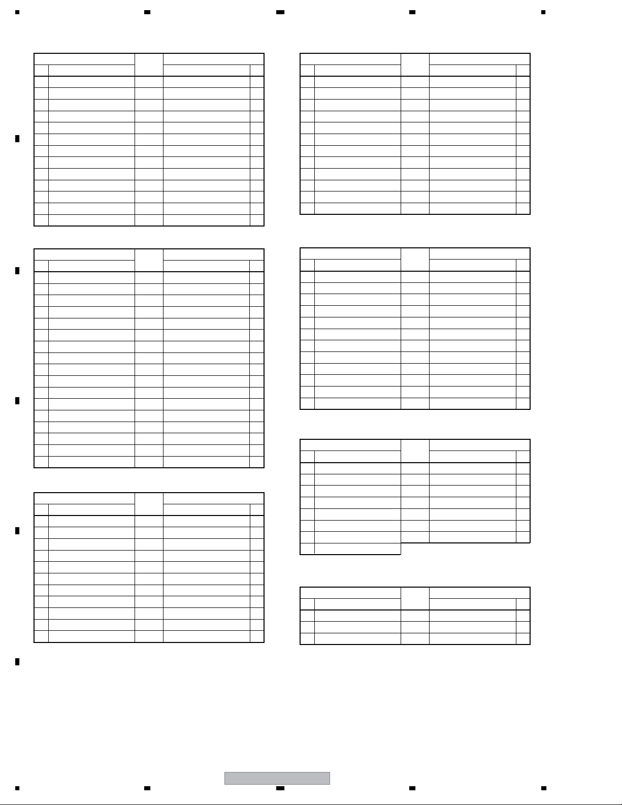
1234
R1 (CN7404)
No. Name Name No.
A
1 V+16.5V 16.7 V+16.5V 1
2 GND 0 GND 2
3 V+12V 12.9 V+12V 3
4 V+12V 12.9 V+12V 4
5 GND 0 GND 5
6 GND 0 GND 6
7 V+6.5V 6.8 V+6.5V 7
8 V+6.5V 6.8 V+6.5V 8
9 GND 0 GND 9
10 GND 0 GND 10
11 V+3V_STB 3.3 V+3V_STB 11
B
12 GND 0 GND 12
13 AC_DET 2.7 AC_DET 13
Voltage
(V)
RGB ASSY VIDEO SLOT I/F ASSYRGB ASSY POWER SUPPLY ASSY
P8
R4 (CN7407)
No. Name Name No.
1 GND 0 GND 1
2 GND 0 GND 2
3 V+13V 13.6 V+13V 3
4 V+13V 13.6 V+13V 4
5 V+12V 12.9 V+12V 5
6 V+12V 12.9 V+12V 6
7 GND 0 GND 7
8 V+3V_STB 3.3 V+3V_STB 8
9 GND 0 GND 9
10 V+3V_DD 3.3 V+3V_DD 10
11 V+3V_DD 3.3 V+3V_DD 11
12 GND 0 GND 12
Voltage
(V)
VS1 (CN8951)
RGB ASSY AV I/O ASSY
R2 (CN6401)
No. Name Name No.
1 VD_SLOT 0 VD_SLOT 1
2 HD_SLOT 0 HD_SLOT 2
3 GNDD 0 GNDD 3
4 B_SLOT 0 B_SLOT 4
5 GNDD 0 GNDD 5
6 G_SLOT 0 G_SLOT 6
C
7 GNDD 0 GNDD 7
8 R_ SLOT 0 R_ SLOT 8
9 VD_ IO 0 VD_ IO 9
10 HD_ IO 5 HD_ IO 10
R13 (CN6402)
1 GNDD 0 GNDD 11
2 B_ IO 0 B_ IO 12
3 GNDD 0 GNDD 13
4 G_ IO 0 G_ IO 14
5 GNDD 0 GNDD 15
6 R_ IO 0 R_ IO 16
D
Voltage
(V)
AV4 (CN8705)
RGB ASSY COMM SLOT I/F ASSY
R3 (CN7406)
No. Name Name No.
1 V+5V_STB 5.1 V+5V_STB 1
2 GND 0 GND 2
3 V+3V_STB 3.3 V+3V_STB 3
4 CYOBI1 3.3 CYOBI1 4
5 CYOBI2 0 CYOBI2 5
6 CYOBI3 0 CYOBI3 6
7 GND 0 GND 7
E
8 SR_OUT 4.9 SR_OUT 8
9 SLOT_ST_COM 3.3 SLOT_ST_COM 9
10 V+6V 6.8 V+6V 10
11 NC
Voltage
(V)
CS2 (CN8902)
RGB ASSY DIGITAL VIDEO ASSY
R5 (CN7408)
No. Name Name No.
1 V+1V_DD 1.4 V+1V_DD 1
2 V+1V_DD 1.4 V+1V_DD 2
3 V+1V_DD 1.4 V+1V_DD 3
4 GND 0 GND 4
5 GND 0 GND 5
6 GND 0 GND 6
7 V+3V_DD 3.3 V+3V_DD 7
8 V+3V_DD 3.3 V+3V_DD 8
9 GND 0 GND 9
10 GND 0 GND 10
11 NC
12 NC
Voltage
(V)
D3 (CN5002)
RGB ASSY FAN (L), (R)
R8 (CN7402)
No. Name Name No.
1 FAN_12V 0 FAN_12V 1
2 FAN_NG 3.2 FAN_NG 2
3 GND 0 GND 3
4 FAN_12V 0 FAN_12V 1
5 FAN_NG 3.2 FAN_NG 2
6 GND
7NC
Voltage
(V)
0 GND 3
FAN (L)
FAN (R)
RGB ASSY TRAP SW (ASG1089)
R6 (CN7204)
No. Name Name No.
1 TRAP_SW 3.3 TRAP_SW 1
2NC 0 NC 2
3 3.3V 3.3 3.3V 3
Voltage
(V)
TRAP SW (CN5801)
F
62
PDP-5004
1234
Page 63

5678
RGB ASSY
R9 (CN5701)
No. Name
AV I/O IF ASSY
CN2102, AV6 (CN2101)
No. Name Name No.
1 N.C. 0 N.C. 101
2 N.C. 0 N.C. 102
3 A_R_SLOT 6 A_R_SLOT 103
4 GND 0 GND 104
5 A_L_SLOT 6 A_L_SLOT 105
6 GND 0 GND 106
7 V+12V 12.9 V+12V 107
8 GND 0 GND 108
9 1N1_HD 4.4 1N1_HD 109
10 1N1_VD 0 1N1_VD 110
11 WE_ROM_B 0 WE_ROM_B 111
12 KEY 3.3 KEY 112
13 IO_YOBI2 3.2 IO_YOBI2 113
14 SR_OUT 5 SR_OUT 114
15 RXD_IF 3.3 RXD_IF 115
16 CLK_IF 3.3 CLK_IF 116
17 RXD_WR 3.3 RXD_WR 117
18 REQ_IF 0 REQ_IF 118
19 RST_IF 0 RST_IF 119
20 IF_CE 3.2 IF_CE 120
21 HOT_P1 0 HOT_P1 121
22 HDMI2_SDA 0 HDMI2_SDA 122
23 HDMI_INT1 3.2 HDMI_INT1 123
24 SCL_AV 3.3 SCL_AV 124
25 HDMI_AUDIO_CLK 3.2 HDMI_AUDIO_CLK 125
26 D_AUDIO_SEL 3.3 D_AUDIO_SEL 126
27 CEC2 0 CEC2 127
28 GND 0 GND 128
29 HD_DVI 0 HD_DVI 129
30 DE_DVI 0 DE_DVI 130
31 GND 0 GND 131
32 RB_DVI7 0/3.3 RB_DVI7 132
33 RB_DVI6 0/3.3 RB_DVI6 133
34 RB_DVI4 0/3.3 RB_DVI4 134
35 RB_DVI2 0/3.3 RB_DVI2 135
36 RB_DVI0 0/3.3 RB_DVI0 136
37 GB_DVI6 0/3.3 GB_DVI6 137
38 GB_DVI4 0/3.3 GB_DVI4 138
39 GB_DVI2 0/3.3 GB_DVI2 139
40 GB_DVI0 0/3.3 GB_DVI0 140
41 BB_DVI6 0/3.3 BB_DVI6 141
42 BB_DVI4 0/3.3 BB_DVI4 142
43 BB_DVI2 0/3.3 BB_DVI2 143
44 BB_DVI0 0/3.3 BB_DVI0 144
45 RA_DVI7 0/3.3 RA_DVI7 145
46 RA_DVI5 0/3.3 RA_DVI5 146
47 RA_DVI3 0/3.3 RA_DVI3 147
48 RA_DVI1 0/3.3 RA_DVI1 148
49 GND 0 GND 149
52 GA_DVI7 0/3.3 GA_DVI7 152
53 GA_DVI5 0/3.3 GA_DVI5 153
54 GA_DVI3 0/3.3 GA_DVI3 154
55 GA_DVI1 0/3.3 GA_DVI1 155
56 BA_DVI7 0/3.3 BA_DVI7 156
Voltage
(V)
AV I/O ASSY
CN8705
RGB ASSY
R9 (CN5701)
No. Name
AV I/O IF ASSY
CN2102, AV6 (CN2101)
No. Name Name No.
57 BA_DVI5 0/3.3 BA_DVI5 157
58 BA_DVI3 0/3.3 BA_DVI3 158
59 GND 0 GND 159
60 V+5V_A2 5 V+5V_A2 160
61 N.C. 0 N.C. 161
62 N.C. 0 N.C. 162
101 N.C. 0 N.C. 1
102 N.C. 0 N.C. 2
103 A_MUTE 0 A_MUTE 3
104 TEMP3 0 - 3.3 TEMP3 4
105 V+6V 6.8 V+6V 5
106 GND 0 GND 6
107 V+3V_A1 3.3 V+3V_A1 7
108 GND 0 GND 8
109 V+3V_UCOM 3.3 V+3V_UCOM 9
110 GND 0 GND 10
111 V+3VSTB 3.3 V+3VSTB 11
112 IO_YOBI1 0 IO_YOBI1 12
113 PN2 0 PN2 13
114 ACTIVE 3.2 ACTIVE 14
115 TXD_IF 3.3 TXD_IF 15
116 TXD_WR 3.3 TXD_WR 16
117 AC_DET 2.6 AC_DET 17
118 IF_BUSY 0 IF_BUSY 18
119 RESET 3.3 RESET 19
120 HDMI_AUDIO_CE 3.3 HDMI_AUDIO_CE 20
121 HOT_P2 3.3 HOT_P2 21
122 HDMI2_SCL 3.3 HDMI2_SCL 22
123 SDA_AV 3.2 SDA_AV 23
124 HDMI_INT2 3.2 HDMI_INT2 24
125 HDMI_AUDIO_TXD 3.3 HDMI_AUDIO_TXD 25
126 CEC1 0 CEC1 26
127 RESETX1 3.3 RESETX1 27
128 VD_DVI 0 VD_DVI 28
129 GND 0 GND 29
130 CLK_DVI 0 CLK_DVI 30
131 GND 0 GND 31
132 GND 0 GND 32
133 RB_DVI5 0/3.3 RB_DVI5 33
134 RB_DVI3 0/3.3 RB_DVI3 34
135 RB_DVI1 0/3.3 RB_DVI1 35
136 GB_DVI7 0/3.3 GB_DVI7 36
137 GB_DVI5 0/3.3 GB_DVI5 37
138 GB_DVI3 0/3.3 GB_DVI3 38
139 GB_DVI1 0/3.3 GB_DVI1 39
140 GND 0 GND 40
141 BB_DVI6 0/3.3 BB_DVI6 41
142 BB_DVI4 0/3.3 BB_DVI4 42
143 BB_DVI2 0/3.3 BB_DVI2 43
144 BB_DVI0 0/3.3 BB_DVI0 44
145 RA_DVI6 0/3.3 RA_DVI6 45
146 RA_DVI4 0/3.3 RA_DVI4 46
147 RA_DVI2 0/3.3 RA_DVI2 47
148 RA_DVI0 0/3.3 RA_DVI0 48
Voltage
(V)
AV I/O ASSY
CN8705
A
B
C
D
E
F
56
PDP-5004
63
7
8
Page 64

1234
RGB ASSY
R9 (CN5701)
No. Name
A
AV I/O IF ASSY
CN2102, AV6 (CN2101)
No. Name Name No.
149 GND 0 GND 49
152 GA_DVI6 0/3.3 GA_DVI6 52
153 GA_DVI4 0/3.3 GA_DVI4 53
154 GA_DVI2 0/3.3 GA_DVI2 54
155 GA_DVI0 0/3.3 GA_DVI0 55
156 BA_DVI6 0/3.3 BA_DVI6 56
157 BA_DVI4 0/3.3 BA_DVI4 57
158 BA_DVI2 0/3.3 BA_DVI2 58
B
159 BA_DVI1 0/3.3 BA_DVI1 59
160 BA_DVI0 0/3.3 BA_DVI0 60
161 NC 0 NC 61
162 NC 0 NC 62
Voltage
(V)
RGB ASSY
R11 (CN7410)
No. Name Name No.
1 GND 0 GND 1
2 KEY 3.3 KEY 2
3EMGREQ1_V 0 EMGREQ1_V 3
4EMGREQ2_V 0 EMGREQ2_V 4
C
5 IC1V_OE 3.3 IC1V_OE 5
6 RESETX1 3.3 RESETX1 6
7 GND 0 GND 7
8 SD_SEL 3.3 SD_SEL 8
9 FNC2 0 FNC2 9
10 FNC3 0 FNC3 10
11 SOUND1 3.3 SOUND1 11
12 GND 0 GND 12
13 DSUBR 3.8 DSUBR 13
14 GND 0 GND 14
15 DSUBG 3.8 DSUBG 15
D
16 GND 0 GND 16
17 DSUBB 3.8 DSUBB 17
18 GND 0 GND 18
19 GND 0 GND 19
20 IN5_HD 0 IN5_HD 20
21 GND 0 GND 21
22 SOUSA_X 3.3 SOUSA_X 22
23 VYOBI1 0 VYOBI1 23
24 VYOBI2 0 VYOBI2 24
25 DSUBSW_DET 3.3 DSUBSW_DET 25
26 GND 0 GND 26
E
27 GND 0 GND 27
28 GND 0 GND 28
29 EMGREQ1_S 0 EMGREQ1_S 29
30 EMGREQ2_S 0 EMGREQ2_S 30
31 IC1S_OE 0 IC1S_OE 31
32 SLOT_ST3 0.4 SLOT_ST3 32
33 M_CHOICE 0 M_CHOICE 33
34 SOUND2 0 SOUND2 34
35 GND 0 GND 35
36 GND 0 GND 36
37 DSUBH 5 DSUBH 37
Voltage
(V)
CN8705
VIDEO SLOT I/F ASSY
VS3 (CN8955)
F
AV I/O ASSY
RGB ASSY
R11 (CN7410)
No. Name Name No.
38 GND 0 GND 38
39 GND 0 GND 39
40 DSUBV 0 DSUBV 40
41 GND 0 GND 41
42 GND 0 GND 42
43 IN5_VD 3.3 IN5_VD 43
44 GND 0 GND 44
45 GND 0 GND 45
46 HYOUJI_X 0 HYOUJI_X 46
47 VYOBI4 0 VYOBI4 47
48 VYOBI5 0 VYOBI5 48
49 VYOBI6 0 VYOBI6 49
50 WE_ROM_B 0 WE_ROM_B 50
Voltage
(V)
VIDEO SLOT I/F ASSY
VS3 (CN8955)
RGB ASSY VIDEO SLOT I/F ASSY
R12 (CN7405)
No. Name Name No.
1 GND 0 GND 1
2 GND 0 GND 2
3 G_SLOT 0 G_SLOT 3
4 GND 0 GND 4
5 B_SLOT 0 B_SLOT 5
6 GND 0 GND 6
7 R_SLOT 0 R_SLOT 7
8 GND 0 GND 8
9 HD_SLOT 0 HD_SLOT 9
10 GND 0 GND 10
11 VD_SLOT 0 VD_SLOT 11
12 GND 0 GND 12
13 AUDIO_L_SLOT 6 AUDIO_L_SLOT 13
14 GND 0 GND 14
15 AUDIO_R_SLOT 6 AUDIO_R_SLOT 15
16 GND 0 GND 16
17 SLOT_ST1 0 SLOT_ST1 17
18 S_DIN_SEL 0 S_DIN_SEL 18
19 FNC_1 0 FNC_1 19
20 FNC_0 5 FNC_0 20
21 NC 0 NC 21
22 NC 0 NC 22
23 VD_DET 0 VD_DET 23
24 GND 0 GND 24
25 HD_DET 0 HD_DET 25
26 GND 0 GND 26
27 VD_IC1 3.2 VD_IC1 27
28 GND 0 GND 28
29 HD_IC1 3 HD_IC1 29
30 GND 0 GND 30
31 GND 0 GND 31
32 RB0_IC1 0/3.3 RB0_IC1 32
33 RB1_IC1 0/3.3 RB1_IC1 33
34 RB2_IC1 0/3.3 RB2_IC1 34
35 RB3_IC1 0/3.3 RB3_IC1 35
36 RB4_IC1 0/3.3 RB4_IC1 36
37 RB5_IC1 0/3.3 RB5_IC1 37
Voltage
(V)
VS4 (CN8953)
64
PDP-5004
1234
Page 65

5678
R12 (CN7405)
No. Name Name No.
38 RB6_IC1 0/3.3 RB6_IC1 38
39 RB7_IC1 0/3.3 RB7_IC1 39
40 GND 0 GND 40
41 GND 0 GND 41
42 GB0_IC1 0/3.3 GB0_IC1 42
43 GB1_IC1 0/3.3 GB1_IC1 43
44 GB2_IC1 0/3.3 GB2_IC1 44
45 GB3_IC1 0/3.3 GB3_IC1 45
46 GB4_IC1 0/3.3 GB4_IC1 46
47 GB5_IC1 0/3.3 GB5_IC1 47
48 GB6_IC1 0/3.3 GB6_IC1 48
49 GB7_IC1 0/3.3 GB7_IC1 49
50 GND 0 GND 50
51 GND 0 GND 51
52 BB0_IC1 0/3.3 BB0_IC1 52
53 BB1_IC1 0/3.3 BB1_IC1 53
54 BB2_IC1 0/3.3 BB2_IC1 54
55 BB3_IC1 0/3.3 BB3_IC1 55
56 BB4_IC1 0/3.3 BB4_IC1 56
57 BB5_IC1 0/3.3 BB5_IC1 57
58 BB6_IC1 0/3.3 BB6_IC1 58
59 BB7_IC1 0/3.3 BB7_IC1 59
60 GND 0 GND 60
61 GND 0 GND 61
62 GND 0 GND 62
63 SCL_VS 3.1 SCL_VS 63
64 GND 0 GND 64
65 SDA_VS 3.1 SDA_VS 65
66 GND 0 GND 66
67 GND 0 GND 67
68 GND 0 GND 68
69 NC 0 NC 69
70 GND 0 GND 70
71 NC 0 NC 71
72 GND 0 GND 72
73 NC 0 NC 73
74 GND 0 GND 74
75 NC 0 NC 75
76 NC 0 NC 76
77 IN4_DET 5 IN4_DET 77
78 IN3_DET 0 IN3_DET 78
79 SLOT_ST2 3 SLOT_ST2 79
80 SR_VS 5.1 SR_VS 80
81 NC
82 3G4G 3.3 3G4G 82
83 GND 0 GND 83
84 GND 0 GND 84
85 IN5_DET 0 IN5_DET 85
86 GND 0 GND 86
87 DE_IC1 2.5 DE_IC1 87
88 GND 0 GND 88
89 CK_IC1 1.5 CK_IC1 89
90 GND 0 GND 90
91 GND 0 GND 91
92 BA7_IC1 0/3.3 BA7_IC1 92
93 BA6_IC1 0/3.3 BA6_IC1 93
94 BA5_IC1 0/3.3 BA5_IC1 94
Voltage
(V)
0
VS4 (CN8953)
NC 81
RGB ASSY VIDEO SLOT I/F ASSYRGB ASSY VIDEO SLOT I/F ASSY
R12 (CN7405)
No. Name Name No.
95 BA4_IC1 0/3.3 BA4_IC1 95
96 BA3_IC1 0/3.3 BA3_IC1 96
97 BA2_IC1 0/3.3 BA2_IC1 97
98 BA1_IC1 0/3.3 BA1_IC1 98
99 BA0_IC1 0/3.3 BA0_IC1 99
100 GND 0 GND 100
101 GND 0 GND 101
102 GA7_IC1 0/3.3 GA7_IC1 102
103 GA6_IC1 0/3.3 GA6_IC1 103
104 GA5_IC1 0/3.3 GA5_IC1 104
105 GA4_IC1 0/3.3 GA4_IC1 105
106 GA3_IC1 0/3.3 GA3_IC1 106
107 GA2_IC1 0/3.3 GA2_IC1 107
108 GA1_IC1 0/3.3 GA1_IC1 108
109 GA0_IC1 0/3.3 GA0_IC1 109
110 GND 0 GND 110
111 GND 0 GND 111
112 RA7_IC1 0/3.3 RA7_IC1 112
113 RA6_IC1 0/3.3 RA6_IC1 113
114 RA5_IC1 0/3.3 RA5_IC1 114
115 RA4_IC1 0/3.3 RA4_IC1 115
116 RA3_IC1 0/3.3 RA3_IC1 116
117 RA2_IC1 0/3.3 RA2_IC1 117
118 RA1_IC1 0/3.3 RA1_IC1 118
119 RA0_IC1 0/3.3 RA0_IC1 119
120 GND 0 GND 120
121 GND 0 GND 121
122 GND 0 GND 122
Voltage
(V)
VS4 (CN8953)
AV I/O ASSY AUDIO AMP ASSY
AV1 (CN7601)
No. Name Name No.
1 A_NG 3.2 A_NG 15
2 TEMP3 0-3.3 TEMP3 14
3 A_MUTE 0 A_MUTE 13
4 ST_BY 2.5 ST_BY 12
5GND 0 GND 11
6 V+6V 6.8 V+6V 10
7 V+3V 3.3 V+3V 9
8 V+12A 12 V+12A 8
9GND 0 GND 7
10 -R_OUT 6 -R_OUT 6
11 +R_OUT 6 +R_OUT 5
12 GND 0 GND 4
13 -L_OUT 6 -L_OUT 3
14 +L_OUT 6 +L_OUT 2
15 GND 0 GND 1
Voltage
(V)
AP2 (CN5001)
AV I/O ASSY KEY CONTROL ASSY
AV2 (CN8702)
No. Name Name No.
1GND 0 GND 1
2 KEY 3.3 KEY 2
3 V+3VSTB 3.3 V+3VSTB 3
Voltage
(V)
KY1 (CN9001)
A
B
C
D
E
F
56
PDP-5004
65
7
8
Page 66

1234
AV I/O ASSY LED ASSY
AV3 (CN8703)
No. Name Name No.
A
1 V+3STB 3.3 V+3STB 1
2 LED_ G 0 LED_ G 2
3 LED_ R 3.3 LED_ R 3
4 GND 0 GND 4
5 AC_ DET 2.6 AC_ DET 5
Voltage
(V)
KY1 (CN9651)
AV I/O ASSY COMM SLOT I/F ASSY
AV5 (CN8704)
No. Name Name No.
1 GND 0 GND 1
2 UART_SW 3.3 UART_SW 2
B
3 KEY 3.3 KEY 3
4 RXD 3.3 RXD 4
5 TXD 3.3 TXD 5
6 GND 0 GND 6
Voltage
(V)
KY1 (CN8905)
AUDIO AMP ASSY POWER SUPPLY ASSY
AP1 (CN5002)
No. Name Name No.
1 V+16R5 16.7 V+16R5 1
2 V+16R5 16.7 V+16R5 2
3 GNDP 0 GNDP 3
C
4 GNDP 0 GNDP 4
5 GNDP 0 GNDP 5
6 GNDP 0 GNDP 6
Voltage
(V)
P6
AUDIO AMP ASSY SP TERMINAL R ASSY
AP3 (CN5003)
No. Name Name No.
1 GND 0 GND 1
2R+ 5.3 R+ 2
3R- 5.2 R- 3
D
4 STBGND 0 STBGND 1
5 TEMP3 0-3.3 TEMP3 2
6 V+3VDD 3.3 V+3VDD 3
7 GND 0 GND 4
8L+ 5.3 L+ 5
9L- 5.2 L- 6
Voltage
(V)
SP2 (CN9801)
SP TERMINAL L ASSY
SP1 (CN9702)
E
F
COMM SLOT I/F ASSY IR ASSY
CS4 (CN8901)
No. Name Name No.
1 V+3STB 3.3 V+3STB 1
2 GND 0 GND 2
3SR0SR3
4 GND 0 GND 4
Voltage
(V)
RE1 (CN4901)
COMM SLOT I/F ASSY COMM SLOT ASSY
CS5 (CN8904)
No. Name Name No.
1NC 0 NC 1
2 IRSW 0 IRSW 2
3 IR_COMM_OUT 4.9 IR_COMM_OUT 3
4 IR_COMM_IN 4.9 IR_COMM_IN 4
5 GND 0 GND 5
6 GND 0 GND 6
7 GND 0 GND 7
8 CYOBI3 0 CYOBI3 8
9 CYOBI2 0 CYOBI2 9
10 CSL_ST2 3.3 CSL_ST2 10
11 CSL_ST1 3.3 CSL_ST1 11
12 12
13 13
14 GND 0 GND 14
15 GND 0 GND 15
16 FIRST_RXD 3.3 FIRST_RXD 16
17 GET_UART 3.3 GET_UART 17
18 INT_EXT 3.3 INT_EXT 18
19 RXD_CARD 0 RXD_CARD 19
20 TXD_CARD 0 TXD_CARD 20
21 GPC5 0 GPC5 21
22 GPC4 0 GPC4 22
23 GPC3 0 GPC3 23
24 GPC2 0 GPC2 24
25 GPC1 0 GPC1 25
101 NC 0 NC 101
102 GND 0 GND 102
103 GND 0 GND 103
104 GND 0 GND 104
105 TXD_PDP 3.3 TXD_PDP 105
106 RXD_PDP 3.3 RXD_PDP 106
107 KEY_COMM_IN 3.3 KEY_COMM_IN 107
108 UART_SW 3.3 UART_SW 108
109 GND 0 GND 109
110 GND 0 GND 110
111 GND 0 GND 111
114 V+6.5V 6.8 V+6.5V 114
115 V+6.5V 6.8 V+6.5V 115
116 GND 0 GND 116
117 GND 0 GND 117
118 V+3VSTB 3.3 V+3VSTB 118
119 V+3VSTB 3.3 V+3VSTB 119
120 NC 0 NC 120
121 NC 0 NC 121
122 NC 0 NC 122
123 NC 0 NC 123
124 V+5VSTB 5 V+5VSTB 124
125 V+5VSTB 5 V+5VSTB 125
Voltage
(V)
CN9454
66
PDP-5004
1234
Page 67

5678
COMM SLOT I/F ASSY VIDEO SLOT I/F ASSY
CS3 (CN8903)
No. Name Name No.
1 GND 0 GND 1
2 FIRST_RXD 3.3 FIRST_RXD 2
3 GET_UART 3.3 GET_UART 3
4 INT_EXT 3.3 INT_EXT 4
5 RXD_GU 0 RXD_GU 5
6 TXD_GU 0 TXD_GU 6
7 GPC5 0 GPC5 7
8 GPC4 0 GPC4 8
9 GPC3 0 GPC3 9
10 GPC2 0 GPC2 10
11 GPC1 0 GPC1 11
Voltage
(V)
VS2 (CN8952)
VIDEO SLOT I/F ASSY VIDEO SLOT 2 ASSY
VS5 (CN8954)
No. Name Name No.
1 GND 0 GND 1
2 GND 0 GND 2
3 G_SLOT 0 G_SLOT 3
4 GND 0 GND 4
5 B_SLOT 0 B_SLOT 5
6 GND 0 GND 6
7 R_SLOT 0 R_SLOT 7
8 GND 0 GND 8
9 HD_SLOT 0 HD_SLOT 9
10 GND 0 GND 10
11 VD_SLOT 0 VD_SLOT 11
12 GND 0 GND 12
13 AUDIO_L_SLOT 6 AUDIO_L_SLOT 13
14 GND 0 GND 14
15 AUDIO_R_SLOT 6 AUDIO_R_SLOT 15
16 GND 0 GND 16
17 SLOT_ST1 0 SLOT_ST1 17
18 S_DIN_SEL 0 S_DIN_SEL 18
19 FNC_1 0 FNC_1 19
20 FNC_0 5 FNC_0 20
21 V+3.3V 3.2 V+3.3V 21
22 V+3.3V 3.2 V+3.3V 22
23 VD_DET 0 VD_DET 23
24 GND 0 GND 24
25 HD_DET 0 HD_DET 25
26 GND 0 GND 26
27 VD 0 VD 27
28 GND 0 GND 28
29 HD 0 HD 29
30 GND 0 GND 30
31 GND 0 GND 31
32 RB0_IC1 0/3.3 RB0_IC1 32
33 RB1_IC1 0/3.3 RB1_IC1 33
34 RB2_IC1 0/3.3 RB2_IC1 34
35 RB3_IC1 0/3.3 RB3_IC1 35
36 RB4_IC1 0/3.3 RB4_IC1 36
37 RB5_IC1 0/3.3 RB5_IC1 37
38 RB6_IC1 0/3.3 RB6_IC1 38
39 RB7_IC1 0/3.3 RB7_IC1 39
40 GND 0 GND 40
41 GND 0 GND 41
42 GB0_IC1 0/3.3 GB0_IC1 42
Voltage
(V)
CN7902
VIDEO SLOT I/F ASSY VIDEO SLOT 2 ASSY
VS5 (CN8954)
No. Name Name No.
43 GB1_IC1 0/3.3 GB1_IC1 43
44 GB2_IC1 0/3.3 GB2_IC1 44
45 GB3_IC1 0/3.3 GB3_IC1 45
46 GB4_IC1 0/3.3 GB4_IC1 46
47 GB5_IC1 0/3.3 GB5_IC1 47
48 GB6_IC1 0/3.3 GB6_IC1 48
49 GB7_IC1 0/3.3 GB7_IC1 49
50 − 50
51 − 51
52 GND 0 GND 52
53 GND 0 GND 53
54 BB0_IC1 0/3.3 BB0_IC1 54
55 BB1_IC1 0/3.3 BB1_IC1 55
56 BB2_IC1 0/3.3 BB2_IC1 56
57 BB3_IC1 0/3.3 BB3_IC1 57
58 BB4_IC1 0/3.3 BB4_IC1 58
59 BB5_IC1 0/3.3 BB5_IC1 59
60 BB6_IC1 0/3.3 BB6_IC1 60
61 BB7_IC1 0/3.3 BB7_IC1 61
62 GND 0 GND 62
63 63
64 64
65 GND 0 GND 65
66 GND 0 GND 66
67 KEY 3.3 KEY 67
68 NC 0 NC 68
69 TXD_CARD 0 TXD_CARD 69
70 RXD_CARD 0 RXD_CARD 70
71 INT_EXT 3.3 INT_EXT 71
72 NC 0 NC 72
73 EMGREQ1_V 0 EMGREQ1_V 73
74 EMGREQ2_V 0 EMGREQ2_V 74
75 IC1V_OE 3.3 IC1V_OE 75
76 RESETX1 3.3 RESETX1 76
77 NC 0 NC 77
78 SD_SEL 3.3 SD_SEL 78
79 FNC2 0 FNC2 79
80 FNC3 0 FNC3 80
81 SOUND1 3.3 SOUND1 81
82 GND 0 GND 82
83 DSUBR 3.8 DSUBR 83
84 GND 0 GND 84
85 DSUBG 3.8 DSUBG 85
86 GND 0 GND 86
87 DSUBB 3.8 DSUBB 87
88 GND 0 GND 88
89 IN5_HD 0 IN5_HD 89
90 SOUSA_X 3.3 SOUSA_X 90
91 GPC1 0 GPC1 91
92 GPC2 0 GPC2 92
93 GPC5 0 GPC5 93
94 VYOBI1 0 VYOBI1 94
95 VYOBI2 0 VYOBI2 95
96 DSUBSW_DET 3.3 DSUBSW_DET 96
101 GND 0 GND 101
102 GND 0 GND 102
103 GND 0 GND 103
Voltage
(V)
CN7902
A
B
C
D
E
F
56
PDP-5004
67
7
8
Page 68

1234
VS5 (CN8954)
No. Name Name No.
A
104 SCL_VS 3.1 SCL_VS 104
105 GND 0 GND 105
106 SDA_VS 3.1 SDA_VS 106
107 GND 0 GND 107
108 GND 0 GND 108
109 GND 0 GND 109
110 V+12V 12.9 V+12V 110
111 GND 0 GND 111
112 NC 0 NC 112
113 GND 0 GND 113
114 V+3.3STB 3.3 V+3.3STB 114
B
115 V+13.5 13.6 V+13.5 115
116 V+13.5 13.6 V+13.5 116
117 IN4_DET 5 IN4_DET 117
118 IN3_DET 0 IN3_DET 118
119 SLOT_ST2 3 SLOT_ST2 119
120 IR 5.1 IR 120
121 NC 0 NC 121
122 NC 0 NC 122
123 GND 0 GND 123
124 GND 0 GND 124
125 3G4G 3.3 3G4G 125
126 IN5_DET 0 IN5_DET 126
C
127 GND 0 GND 127
128 DE 2.5 DE 128
129 GND 0 GND 129
130 CLK 1.5 CLK 130
131 GND 0 GND 131
132 BA7_IC1 0/3.3 BA7_IC1 132
133 BA6_IC1 0/3.3 BA6_IC1 133
134 BA5_IC1 0/3.3 BA5_IC1 134
135 BA4_IC1 0/3.3 BA4_IC1 135
136 BA3_IC1 0/3.3 BA3_IC1 136
137 BA2_IC1 0/3.3 BA2_IC1 137
D
138 BA1_IC1 0/3.3 BA1_IC1 138
139 BA0_IC1 0/3.3 BA0_IC1 139
140 GND 0 GND 140
141 GND 0 GND 141
142 GA7_IC1 0/3.3 GA7_IC1 142
143 GA6_IC1 0/3.3 GA6_IC1 143
144 GA5_IC1 0/3.3 GA5_IC1 144
145 GA4_IC1 0/3.3 GA4_IC1 145
146 GA3_IC1 0/3.3 GA3_IC1 146
147 GA2_IC1 0/3.3 GA2_IC1 147
148 GA1_IC1 0/3.3 GA1_IC1 148
149 GA0_IC1 0/3.3 GA0_IC1 149
E
150 150
151 151
152 GND 0 GND 152
153 GND 0 GND 153
154 RA7_IC1 0/3.3 RA7_IC1 154
155 RA6_IC1 0/3.3 RA6_IC1 155
156 RA5_IC1 0/3.3 RA5_IC1 156
157 RA4_IC1 0/3.3 RA4_IC1 157
158 RA3_IC1 0/3.3 RA3_IC1 158
159 RA2_IC1 0/3.3 RA2_IC1 159
160 RA1_IC1 0/3.3 RA1_IC1 160
F
Voltage
(V)
CN7902
VIDEO SLOT I/F ASSY VIDEO SLOT 2 ASSYVIDEO SLOT I/F ASSY VIDEO SLOT 2 ASSY
VS5 (CN8954)
No. Name Name No.
161 RA0_IC1 0/3.3 RA0_IC1 161
162 GND 0 GND 162
163 163
164 164
165 GND 0 GND 165
166 GND 0 GND 166
167 VSEPSCL 3.3 VSEPSCL 167
168 VSEPSDA 3.3 VSEPSDA 168
169 NC 0 NC 169
170 GET_UART 3.3 GET_UART 170
171 FIRST_RXD 3.3 FIRST_RXD 171
172 NC 0 NC 172
173 EMGREQ1_S 0 EMGREQ1_S 173
174 EMGREQ2_S 0 EMGREQ2_S 174
175 IC1S_OE 0 IC1S_OE 175
176 NC 0 NC 176
177 NC 0 NC 177
178 NC 0 NC 178
179 SLOT_ST3 0.4 SLOT_ST3 179
180 M_CHOICE 0 M_CHOICE 180
181 SOUND2 0 SOUND2 181
182 GND 0 GND 182
183 GND 0 GND 183
184 DSUBH 5 DSUBH 184
185 GND 0 GND 185
186 DSUBV 0 DSUBV 186
187 GND 0 GND 187
188 GND 0 GND 188
189 IN5_VD 3.3 IN5_VD 189
190 HYOUJI_X 0 HYOUJI_X 190
191 GPC3 0 GPC3 191
192 GPC4 0 GPC4 192
193 NC 0 NC 193
194 VYOBI4 0 VYOBI4 194
195 VYOBI5 0 VYOBI5 195
196 VYOBI6 0 VYOBI6 196
Voltage
(V)
CN7902
KEY CONTROL ASSY FRONT KEY ASSY
KY2 (CN9002)
No. Name Name No.
1D7 0/3.3 D7 1
2D6 0/3.3 D6 2
3D5 0/3.3 D5 3
4G0 0/3.3 G0 4
5G1 0/3.3 G1 5
6G2 0/3.3 G2 6
Voltage
(V)
KY4 (CN9400)
68
PDP-5004
1234
Page 69

5678
5. PCB PARTS LIST
NOTES:
Parts marked by "NSP" are generally unavailable because they are not in our Master Spare Parts List.
The mark found on some component parts indicates the importance of the safety factor of the part.
Therefore, when replacing, be sure to use parts of identical designation.
When ordering resistors, first convert resistance values into code form as shown in the following examples.
Ex.1 When there are 2 effective digits (any digit apart from 0), such as 560 ohm and 47k ohm (tolerance is shown by J=5%,
and K=10%).
560 Ω
47k Ω
0.5 Ω
1 Ω
56 x 10
47 x 10
R50
1R0
1
3
Ex.2 When there are 3 effective digits (such as in high precision metal film resistors).
5.62k Ω
1
Mark No. Description Part No.
LIST OF ASSEMBLIES for PDP-5004,
PDP-5014 models
NSP 1..50 ADDRESS ASSY AWV2121
NSP 2..50 ADDRESS ASSY AWZ6839
NSP 1..50 SCAN FUKUGO ASSY AWV2036
NSP 2..50 SCAN A ASSY AWZ6809
NSP 2..50 SCAN B ASSY AWZ6810
NSP 2..X CONNECTOR A ASSY AWZ6811
NSP 2..X CONNECTOR B ASSY AWZ6812
NSP 1..50 X DRIVE ASSY AWV2143
2..PANEL SENSOR ASSY AWZ6795
2..50 X DRIVE ASSY AWZ6959
1..50 Y DRIVE ASSY AWV2144
NSP 1..CM RGB ASSY AWV2150
2..RGB ASSY AWZ6961
NSP 1..CMS FUKUGO ASSY(PDP-5004)AWV2151
NSP 1..CMB FUKUGO ASSY(PDP-5014)AWV2152
2..AUDIO AMP ASSY AWZ6848
2..VIDEO SLOT I/F ASSY AWZ6851
2..IR RECEIVE ASSY AWZ6855
2..SP TERMINAL L ASSY AWZ6856
2..SP TERMINAL R ASSY AWZ6857
2..COVER ASSY AWZ6858
2..AV I/O I/F ASSY AWZ6859
2..COMM SLOT I/F ASSY AWZ6964
2..LED ASSY AWZ6966
2..AV I/O ASSY (PDP-5004) AWZ6967
2..AV I/O ASSY (PDP-5014) AWZ6971
2..COMM SLOT ASSY AWZ6968
2..KEY CONTROL ASSY AWZ6969
2..FRONT KEY ASSY AWZ6970
1..DIGITAL VIDEO ASSY AWV2100
1..VIDEO SLOT2 ASSY AWV2159
561
473
5621
RD1/4PU J
RD1/4PU J
RN2H K
RS1P K
RN1/4PC F562 x 10
561
473
R50
1R0
5621
Mark No. Description Part No.
LIST OF ASSEMBLIES for PDP-4304,
PDP-4314 models
NSP 1..43 ADDRESS ASSY AWV2120
NSP 2..43 ADDRESS ASSY AWZ6793
NSP 1..43 SCAN FUKUGO ASSY AWV2023
NSP 2..43 SCAN A ASSY AWZ6796
NSP 2..43 SCAN B ASSY AWZ6797
NSP 2..X CONNECTOR A ASSY AWZ6798
NSP 2..X CONNECTOR B ASSY AWZ6799
NSP 1..43 X DRIVE ASSY AWV2021
2..PANEL SENSOR ASSY AWZ6795
2..43 X DRIVE ASSY AWZ6840
1..43 Y DRIVE ASSY AWV2022
NSP 1..CM RGB ASSY AWV2150
2..RGB ASSY AWZ6961
NSP 1..CMS FUKUGO ASSY(PDP-4304)AWV2151
NSP 1..CMB FUKUGO ASSY(PDP-4314)AWV2152
2..AUDIO AMP ASSY AWZ6848
2..VIDEO SLOT I/F ASSY AWZ6851
2..IR RECEIVE ASSY AWZ6855
2..SP TERMINAL L ASSY AWZ6856
2..SP TERMINAL R ASSY AWZ6857
2..COVER ASSY AWZ6858
2..AV I/O I/F ASSY AWZ6859
2..COMM SLOT I/F ASSY AWZ6964
2..LED ASSY AWZ6966
2..AV I/O ASSY (PDP-4304) AWZ6967
2..AV I/O ASSY (PDP-4314) AWZ6971
2..COMM SLOT ASSY AWZ6968
2..KEY CONTROL ASSY AWZ6969
2..FRONT KEY ASSY AWZ6970
1..DIGITAL VIDEO ASSY AWV2100
1..VIDEO SLOT2 ASSY AWV2159
A
B
C
D
E
CONTRAST OF PCB ASSEMBLIES
AV I/O ASSY
AWZ6967 and AWZ6971 are constructed the same except
for the following :
Mark No. Description AWZ6967 AWZ6971
[IF UCOM BLOCK]
R8743 RS1/16S103J Not used
R8744 Not used RS1/16S103J
PDP-5004
56
F
69
7
8
Page 70

1234
PCB PARTS LIST for PDP-5004, PDP-5014 models
Mark No. Description Part No.
50 ADDRESSASSY
A
[50 ADR LOGICBLOCK]
SEMICONDUCTORS
IC1501 PEE001B
COILS AND FILTERS
F1501-F1503 ATF1194
CAPACITORS
C1553, C1556, C1559, C1560, C1563 ACG1105
C1501, C1502 ACH1357
C1503-C1507, C1552, C1555, C1558 CKSSYF104Z16
C1561, C1564 CKSSYF104Z16
B
RESISTORS
R1510, R1519, R1522, R1526 RAB4C470J
R1513-R1518 RS1/16SS470J
R1505-R1509 RS1/16SS1000F
Other Resistors RS1/16S###J
OTHERS
CN1501 40P FFC CONNECTOR AKM1215
[50 ADR RESONANCE BLOCK]
SEMICONDUCTORS
C
IC1601-IC1603 TND304S
Q1604 2SA1163
Q1601 HAT1081R
Q1602, Q1603 HAT3019R
D1601 1SS302
Mark No. Description Part No.
C3023, C3024, C3034, C3035 ACG1088
(0.1microF/250V)
C3045, C3046, C3056, C3057 ACG1088
(0.1microF/250V)
C3005, C3008, C3016, C3019, C3026 CCSRCH101J50
C3029, C3037, C3040, C3048, C3051 CCSRCH101J50
C3060, C3063 CCSRCH101J50
C3004 CCSRCH151J50
C3007, C3018, C3033, C3044, C3050 CCSRCH181J50
C3062 CCSRCH181J50
C3006, C3011, C3017, C3022 CCSRCH331J50
C3031, C3032, C3042, C3043, C3049 CCSRCH331J50
C3055, C3061, C3066 CCSRCH331J50
C3009, C3010, C3020, C3021, C3028 CCSRCH390J50
C3030, C3039, C3041, C3053, C3054 CCSRCH390J50
C3064, C3065 CCSRCH390J50
C3003, C3014, C3025, C3036, C3047 CKSRYB105K6R3
C3058 CKSRYB105K6R3
RESISTORS
R3003, R3011, R3017, R3025, R3030 RAB4C221J
R3036 RAB4C221J
Other Resistors RS1/16S###J
OTHERS
CN3001 15P CONNECTOR AKP1218
K3001, K3004, K3009, K3015, K3017 AKX9002
TEST PIN
K3019, K3021 TEST PIN AKX9002
D1608, D1609, D1617, D1618 EC10UA20
D1610, D1611, D1616, D1619, D1620 EC11FS2
D1604, D1612 MA126
D1602, D1606, D1607, D1614, D1615 UDZS15B
D1621, D1622 UDZS24B
COILS AND FILTERS
D
L1601, L1602 ATH1135
CAPACITORS
C1609, C1615 (0.47microF) ACE1172
C1605, C1607, C1608, C1613, C1614 ACG1101
(0.01microF/100V)
C1618 ACH1357
C1603 (47microF/16V) ACH1391
C1601, C1602 (56microF/80V) ACH1405
C1604, C1606, C1612 CKSSYF104Z16
E
RESISTORS
R1631 ACN1174
R1633 RS1/16S1202F
R1632 RS1/16S1502F
Other Resistors RS1/16S###J
50 SCAN A ASSY
SEMICONDUCTORS
IC3001-IC3006 AN16003A
D3001 KU10N16
F
CAPACITORS
C3001, C3002, C3012, C3013 ACG1088
(0.1microF/250V)
70
1234
50 SCAN B ASSY
SEMICONDUCTORS
IC3201-IC3206 AN16003A
D3201 KU10N16
CAPACITORS
C3201, C3211, C3212, C3222, C3223 ACG1088
(0.1microF/250V)
C3233, C3234, C3244, C3245 ACG1088
(0.1microF/250V)
C3255, C3256, C3266 ACG1088
(0.1microF/250V)
C3203, C3204, C3214, C3215, C3226 CCSRCH101J50
C3228, C3237, C3239, C3247, C3251 CCSRCH101J50
C3258, C3259 CCSRCH101J50
C3262 CCSRCH151J50
C3206, C3217, C3232, C3243, C3249 CCSRCH181J50
C3261 CCSRCH181J50
C3205, C3210, C3216, C3221 CCSRCH331J50
C3230, C3231, C3241, C3242, C3248 CCSRCH331J50
C3254, C3260, C3265 CCSRCH331J50
C3208, C3209, C3219, C3220, C3227 CCSRCH390J50
C3229, C3238, C3240, C3252, C3253 CCSRCH390J50
C3263, C3264 CCSRCH390J50
C3202, C3213, C3224, C3235, C3246 CKSRYB105K6R3
C3257 CKSRYB105K6R3
RESISTORS
R3202, R3210, R3216, R3224, R3229 RAB4C221J
R3235 RAB4C221J
Other Resistors RS1/16S###J
PDP-5004
Page 71

5678
Mark No. Description Part No.
OTHERS
CN3201 15P CONNECTOR AKP1218
K3203, K3208, K3214, K3216, K3218 AKX9002
TEST PIN
K3220, K3221 TEST PIN AKX9002
Mark No. Description Part No.
RESISTORS
R1116, R1122 RS1/10S1003F
R1133, R1143-R1145 RS1/10S100J
R1103, R1106, R1110, R1111 RS1/10S2R2J
R1118, R1119, R1123, R1126, R1153 RS1/10S2R2J
R1136 RS1/16S1202F
A
X CONNECTOR A ASSY
This assembly has no service part.
X CONNECTOR B ASSY
This assembly has no service part.
50 X DRIVE ASSY
[50 X LOGIC BLOCK]
SEMICONDUCTORS
IC1002 TC74ACT540FT
IC1001 TC74ACT541FT
IC1003 TC74VHC08FT
CAPACITORS
C1001 CEHAT470M25
C1002-C1004 CKSRYB104K16
RESISTORS
R1001, R1002, R1005 RAB4C470J
R1003, R1004, R1007 RAB4C472J
OTHERS
CN1001 30P FFC CONNECTOR AKM1218
[50 X RESONANCE BLOCK]
SEMICONDUCTORS
IC1103 BA10393F
IC1101, IC1102 TND506MD
Q1113 2SC2412K
Q1102, Q1103, Q1111, Q1112 2SK3560
Q1105, Q1106, Q1108, Q1109 2SK3723
Q1101, Q1104, Q1107, Q1110 CPH5506
D1109, D1122 1SS302
D1131, D1132 1SS355
D1101, D1102, D1104, D1105 EC11FS4
D1107, D1108, D1111, D1114-D1117 EC11FS4
D1120, D1121, D1127, D1128 EC11FS4
D1103, D1118, D1124, D1125, D1130 FCU20A30
D1113, D1129 RF2001T3D
D1110, D1123 UDZS16B
COILS AND FILTERS
L1103, L1105 ATH1119
L1104 ATH1155
L1102 ATH1156
L1101 LFEA470J
R1139 RS1/16S3301F
R1130 RS1/16S5601F
R1134 RS1/16S8201F
R1113, R1128 RS1MMF101J
VR1101-VR1104 CCP1390
Other Resistors RS1/16S###J
OTHERS
3301 SPACER AEH1075
3501 SCREW PMH30P080FMC
[50 X SUS BLOCK]
SEMICONDUCTORS
IC1202 HCPL-M611
IC1205 NJM2872F05
IC1203, IC1207 STK795-512
IC1208 TLP181(P-GR)
IC1204, IC1206 TND301S
Q1207 2SC2412K
Q1203 2SD1898
Q1302 2SJ522
Q1301 2SK2503
Q1205 2SK3116-Z
Q1206, Q1208 DTC124EK
Q1201 HN1B04FU
D1212 1SS302
D1211, D1213, D1216 1SS355
D1201, D1207 EC10QS04
D1204, D1301 EC11FS4
D1214 EC8FS6
D1208 UDZS5.6B
COILS AND FILTERS
L1204, L1205 ATH1112
L1202 LFEA100J
L1203, L1206 LFEA470J
CAPACITORS
C1214-C1217, C1227-C1230 ACE1163
C1233 ACE1169
C1244 ACE1170
C1209 (0.1microF/630V) ACG1092
C1219, C1231 ACH1358
C1224 CEHAT101M16
C1301 CEHAT221M25
C1203, C1207, C1210, C1220, C1223 CEHAT470M25
C1238, C1239 CEHAT470M25
C1235 CKSRYB102K50
B
C
D
E
CAPACITORS
C1112-C1114, C1125-C1127 ACE1168
C1111, C1124 (100pF/630V) ACG1104
C1109, C1119 (0.1microF/630V) ACG1108
C1101, C1105, C1116, C1117 CCSRCH331J50
C1128, C1130-C1132 CKSRYB104K16
C1102, C1118 CKSRYB105K6R3
C1104, C1108, C1115, C1122 CKSYB105K25
56
RESISTORS
PDP-5004
C1213, C1225, C1240, C1241, C1243 CKSRYB104K16
C1202, C1205, C1206, C1212, C1302 CKSRYF104Z50
R1230 ACN1166
R1208, R1321, R1322 ACN1174
R1304 ACN1195
7
8
F
71
Page 72

1234
Mark No. Description Part No.
R1305 ACN1198
R1301, R1302, R1314 RS1/10S122J
R1226, R1251 RS1MMF331J
A
R1235, R1236 RS2MMF121J
Other Resistors RS1/16S###J
OTHERS
KN1201-KN1205, KN1208-KN1214 ANK-142
GROUND PLATE
CN1201 12P TOP POST B12B-EH
[50 X D-D CON BLOCK]
SEMICONDUCTORS
IC1404 AN1431M
B
IC1402 MIP161
IC1401, IC1403 TLP181(P-GR)
Q1401 2SA1037K
Q1402 2SC2412K
Mark No. Description Part No.
RESISTORS
R1076, R1078 RS1/16S1001F
Other Resistors RS1/16S###J
50 Y DRIVE ASSY
[50 Y LOGIC BLOCK]
SEMICONDUCTORS
IC2002 TC74ACT540FT
IC2001, IC2003 TC74ACT541FT
IC2005 TC74VHC08FT
IC2004 TC74VHC541FT
Q2001 DTC124EK
CAPACITORS
C2001 CEHAT470M16
C2010, C2011 CKSRYB104K16
C2002-C2006 CKSRYF104Z50
D1407, D1408 EC11FS2
D1404 EC8FS6
D1401, D1403 UDZS5.6B
COILS AND FILTERS
L1401 ATH1110
T1401 ATK1153
C
CAPACITORS
C1401, C1402 ACH1361
C1404 CEHAT101M16
C1405 CEHAT101M25
C1409 CEHAT331M16
C1403, C1407, C1408, C1411 CKSRYB104K16
C1406 CKSRYF104Z50
RESISTORS
R1405, R1406, R1408-R1410, R1414 RS1/10S3602F
R1420 RS1/16S1101F
D
R1403 RS1/16S2702F
R1401, R1404 RS1/16S4701F
R1417 RS1/16S7500F
VR1401 CCP1390
Other Resistors RS1/16S###J
OTHERS
1002 CARD SPACER AEC1957
1001 DRIVE SIRICON SHEET AEH1062
1001 PLATE X ANG2622
1001 DRIVE HEATSINK A ANH1613
1001 SCREW BMZ30P080FZK
E
1002 SCREW PMB30P060FNI
RESISTORS
R2018, R2019 RAB4C102J
R2002, R2004, R2013-R2015 RAB4C470J
R2005, R2006, R2012, R2016, R2017 RAB4C472J
Other Resistors RS1/16S###J
OTHERS
CN2001 AKM1201
[50 Y RESONANCE BLOCK]
SEMICONDUCTORS
IC2211 BA10393F
IC2201, IC2202 TND506MD
Q2213 2SC2412K
Q2202, Q2211, Q2212, Q2214 2SK3560
Q2205, Q2206, Q2208, Q2209 2SK3723
Q2201, Q2204, Q2207, Q2210 CPH5506
D2209, D2223 1SS302
D2230, D2232 1SS355
D2202-D2205, D2207, D2208 EC11FS4
D2213, D2214, D2216-D2219, D2222 EC11FS4
D2226, D2227 EC11FS4
D2201, D2206, D2211, D2220, D2229 FCU20A30
D2215, D2228 RF2001T3D
D2210, D2224 UDZS16B
COILS AND FILTERS
L2203, L2205 CHOKE COIL ATH1119
L2204 CHOKE COIL ATH1155
L2202 CHOKE COIL ATH1156
L2201 LFEA470J
PANEL SENSOR ASSY
SEMICONDUCTORS
IC1072 MM1522XU
IC1071 MM3012XN
CAPACITORS
C1075 ACH1357
C1074 CKSRYB103K50
F
C1071, C1076 CKSRYB104K16
C1072, C1073 CKSRYF105Z10
72
1234
CAPACITORS
C2212-C2214, C2225-C2227 ACE1168
C2211, C2224 (100pF/630V) ACG1104
C2210, C2223 (0.1microF/630V) ACG1108
C2202, C2205, C2216, C2217 CCSRCH331J50
C2230, C2232, C2233, C2235 CKSRYB104K16
C2203, C2218 CKSRYB105K6R3
C2201, C2208, C2215, C2219 CKSYB105K25
RESISTORS
R2240, R2241 RS1/10S1003F
R2244-R2247 RS1/10S100J
PDP-5004
Page 73

5678
Mark No. Description Part No.
R2204, R2205, R2211, R2213 RS1/10S2R2J
R2220, R2221, R2224, R2228, R2253 RS1/10S2R2J
R2234 RS1/16S1202F
R2235 RS1/16S3301F
R2233 RS1/16S5601F
R2242 RS1/16S8201F
R2215, R2230 RS1MMF101J
VR2201-VR2204 CCP1390
Other Resistors RS1/16S###J
OTHERS
3301 SPACER AEH1075
3501 SCREW PMH30P080FMC
[50 Y SUS BLOCK]
SEMICONDUCTORS
IC2302, IC2308 HCPL-M611
IC2305 NJM2872F05
IC2303, IC2307 STK795-513
IC2301, IC2304, IC2309 TND301S
Q2310 2SC2412K
Mark No. Description Part No.
OTHERS
KN2301-KN2305, KN2310-KN2312 ANK-142
KN2314-KN2316 GROUND PLATE ANK-142
CN2301 11P TOP POST B11B-EH
[50 Y SCAN BLOCK]
SEMICONDUCTORS
IC2101, IC2103-IC2106,IC2108,IC2109 HCPL-M611
IC2102, IC2107 TC74ACT540FT
COILS AND FILTERS
L2101-L2103 LFEA100J
CAPACITORS
C2104, C2111, C2116, C2117 ACH1392
C2101, C2107, C2113 CEHAT221M16
C2102, C2103, C2105, C2106 CKSRYB104K16
C2108-C2110, C2112, C2114 CKSRYB104K16
RESISTORS
R2121, R2128 RAB4C472J
Other Resistors RS1/16S###J
A
B
Q2303, Q2307 2SD1898
Q2301 2SJ522
Q2302, Q2308, Q2312 2SK3325-Z
Q2309 HN1B04FU
D2302 1SS302
D2319, D2320 EC10QS04
D2305 EC11FS4
D2301 UDZS16B
D2306, D2318 UDZS5.6B
COILS AND FILTERS
L2306, L2307 ATH1112
L2304 LFEA100J
L2308 LFEA101J
L2301, L2302, L2305 LFEA470J
CAPACITORS
C2309-C2312, C2326, C2327 ACE1163
C2329, C2330 ACE1163
C2314 ACE1165
C2302 ACG1092
C2316, C2331 ACH1358
C2303 ACH1361
C2336 ACH1393
C2306, C2334 CEHAT221M25
C2308, C2324, C2339, C2340 CEHAT470M16
C2304, C2320, C2338 CEHAT470M25
C2305, C2322, C2323, C2325, C2333 CKSRYB104K16
C2341 CKSRYB104K16
C2301, C2307, C2328 CKSRYF104Z50
RESISTORS
R2332 ACN1166
R2364, R2365 ACN1174
R2309 RS1MMF132J
R2310, R2311 RS1MMF472J
R2312-R2314, R2322, R2323 RS3LMF100J
R2348, R2352, R2358, R2359 RS3LMF1R8J
Other Resistors RS1/16S###J
OTHERS
CN2101, CN2102 15P CONNECTOR AKM1200
[50 Y D-D CON BLOCK]
SEMICONDUCTORS
IC2410-IC2412 AN1431M
IC2406 BA10358F
IC2401 MIP0223SC
IC2402-IC2405, IC2407-IC2409 TLP181(P-GR)
Q2402, Q2407 2SA1037K
Q2410 2SA1163
Q2417 2SA1535
Q2411-Q2414, Q2416 2SC2412K
Q2405 2SC2713
Q2403 2SD1664
Q2401, Q2404 2SD1898
Q2415 HN1C01FU
D2430 1SS301
D2410, D2419, D2436 1SS302
D2409, D2418 1SS355
D2404-D2407 EC11FS2
D2403, D2414 EC11FS4
D2402 EC8FS6
D2427 RD91PA
D2401 U1ZB330
D2412, D2413, D2422 UDZS15B
D2425, D2426 UDZS27B
D2415 UDZS33B
D2432 UDZS4.3B
D2423, D2431 UDZS5.6B
COILS AND FILTERS
T2402 ATK1156
T2403 ATK1157
T2401 ATK1158
L2402 LFEA100J
L2401 LFEA101J
L2403 LFEA470J
C
D
E
F
56
PDP-5004
73
7
8
Page 74

1234
Mark No. Description Part No.
CAPACITORS
C2406 ACH1360
C2401 ACH1361
A
C2427 CEHAT100M50
C2403 CEHAT101M16
C2405, C2407, C2417 CEHAT101M25
C2414 CEHAT221M16
C2410 CEHAT221M25
C2411 CEHAT331M25
C2420 CEHAT470M2A
C2409, C2419 CKSRYB103K50
C2402, C2412, C2413, C2423, C2425 CKSRYB104K16
C2431, C2432, C2434-C2436 CKSRYB104K16
C2441-C2443 CKSRYB104K16
B
C2415, C2421, C2428 CKSRYB105K6R3
C2404, C2408, C2416, C2418, C2426 CKSRYF104Z50
C2429 CKSRYF104Z50
RESISTORS
R2429 ACN1225
R2435, R2439 RS1/10S2202F
R2402-R2404 RS1/10S3902F
R2442 RS1/16S1201F
R2468 RS1/16S1202F
R2424 RS1/16S2001F
C
R2420, R2427, R2438 RS1/16S2201F
R2467 RS1/16S3301F
R2457-R2460 RS1/16S4701F
R2506 RS3LMF151J
VR2401, VR2402 CCP1390
Other Resistors RS1/16S###J
OTHERS
2401 HEATSINK ANH1614
2401 SCREW BBZ30P080FZK
2002 CARD SPACER AEC1957
2001 DRIVE SIRICON SHEET AEH1062
D
2001 PLATE Y ANG2557
2001 DRIVE HEATSINK A ANH1613
2001 SCREW BMZ30P080FZK
2002 SCREW PMB30P060FNI
PCB PARTS LIST for PDP-4304, PDP-4314
models
43 ADDRESS ASSY
E
[ADR LOGIC BLOCK]
SEMICONDUCTORS
IC1501 PEE001B
COILS AND FILTERS
F1501-F1503 ATF1194
CAPACITORS
C1556,C1559,C1560,C1563 ACG1105
(330p/100V)
C1501,C1502(47/6.3V) ACH1357
C1503-C1507,C1555,C1558,C1561 CKSSYF104Z16
F
C1564 CKSSYF104Z16
Mark No. Description Part No.
R1513-R1518 RS1/16SS470J
R1505-R1509 RS1/16SS1000F
Other Resistors RS1/16S###J
OTHERS
CN1501 40P FFC CONNECTOR AKM1215
[ADR RESONANNCE BLOCK]
SEMICONDUCTORS
IC1601-IC1603 TND304S
Q1604 2SA1163
Q1601 HAT1081R
Q1602,Q1603 HAT3019R
D1601 1SS302
D1608,D1609,D1617,D1618 EC10UA20
D1610,D1611,D1616,D1619,D1620 EC11FS2
D1604,D1612 MA126
D1602,D1606,D1607,D1614,D1615 UDZS15B
D1621,D1622 UDZS24B
COILS AND FILTERS
L1601,L1602 ATH1135
CAPACITORS
C1609,C1615 (0.47/100V) ACE1172
C1605,C1607,C1608,C1613,C1614 ACG1101
(0.01/100V)
C1618 (47/6.3V) ACH1357
C1603 (47/16V) ACH1391
C1601,C1602 (56/80V) ACH1405
C1604,C1606,C1612 CKSSYF104Z16
RESISTORS
R1631 (10,1/2W) ACN1174
Other Resistors RS1/16S###J
43 SCAN A ASSY
SEMICONDUCTORS
IC3001-IC3006 SN755864APZP
D3001 KU10N16
CAPACITORS
C3001,C3002,C3012,C3013 ACG1088
C3023,C3024,C3034,C3035 ACG1088
C3045,C3046,C3056,C3057 ACG1088
(0.1/250V)
C3005,C3008,C3016,C3019,C3026 CCSRCH101J50
C3029,C3037,C3040,C3048,C3051 CCSRCH101J50
C3060,C3063 CCSRCH101J50
C3007,C3018,C3033,C3044,C3050 CCSRCH181J50
C3062 CCSRCH181J50
C3006,C3011,C3017,C3022 CCSRCH331J50
C3031,C3032,C3042,C3043,C3049 CCSRCH331J50
C3055,C3061,C3066 CCSRCH331J50
C3009,C3010,C3020,C3021,C3028 CCSRCH390J50
C3030,C3039,C3041,C3053,C3054 CCSRCH390J50
C3064,C3065 CCSRCH390J50
C3003,C3014,C3025,C3036,C3047 CKSRYB105K6R3
C3058 CKSRYB105K6R3
RESISTORS
R1510,R1519,R1522 RAB4C470J
74
1234
RESISTORS
PDP-5004
Page 75

5678
Mark No. Description Part No.
R3003,R3011,R3017,R3025,R3030 RAB4C221J
R3036 RAB4C221J
Other Resistors RS1/16S###J
OTHERS
CN3001 15P CONNECTOR AKP1218
K3001,K3004,K3009,K3015,K3017 AKX9002
K3019,K3021 TEST PIN AKX9002
Mark No. Description Part No.
IC1001 TC74ACT541FT
IC1003 TC74VHC08FT
CAPACITORS
C1001 CEHAT470M25
C1002-C1004 CKSRYB104K16
RESISTORS
R1001,R1002,R1005 RAB4C470J
R1003,R1004,R1007 RAB4C472J
A
43 SCAN B ASSY
SEMICONDUCTORS
IC3201-IC3206 SN755864APZP
D3201 KU10N16
CAPACITORS
C3201,C3211,C3212,C3222,C3223 ACG1088
C3233,C3234,C3244,C3245 ACG1088
C3255,C3256,C3266 (0.1/250V) ACG1088
C3203,C3204,C3214,C3215,C3226 CCSRCH101J50
C3228,C3237,C3239,C3247,C3251 CCSRCH101J50
C3258,C3259 CCSRCH101J50
C3206,C3217,C3232,C3243,C3249 CCSRCH181J50
C3261 CCSRCH181J50
C3205,C3210,C3216,C3221 CCSRCH331J50
C3230,C3231,C3241,C3242,C3248 CCSRCH331J50
C3254,C3260,C3265 CCSRCH331J50
C3208,C3209,C3219,C3220,C3227 CCSRCH390J50
C3229,C3238,C3240,C3252,C3253 CCSRCH390J50
C3263,C3264 CCSRCH390J50
C3202,C3213,C3224,C3235,C3246 CKSRYB105K6R3
C3257 CKSRYB105K6R3
RESISTORS
R3202,R3210,R3216,R3224,R3229 RAB4C221J
R3235 RAB4C221J
Other Resistors RS1/16S###J
OTHERS
CN3201 15P CONNECTOR AKP1218
K3203,K3208,K3214,K3216,K3218 AKX9002
K3220,K3221 TEST PIN AKX9002
OTHERS
CN1001 30P FFC CONNECTOR AKM1218
[RESONANCE BLOCK]
SEMICONDUCTORS
IC1103 BA10393F
IC1101,IC1102 TND506MD
Q1113 2SC2412K
Q1102,Q1103,Q1111,Q1112,Q1114 2SK3560
Q1105,Q1106,Q1108,Q1109 2SK3723
Q1101,Q1104,Q1107,Q1110 CPH5506
D1109,D1122 1SS302
D1112,D1119 1SS355
D1101,D1102,D1104,D1105 EC11FS4
D1107,D1108,D1111,D1114-D1117 EC11FS4
D1120,D1121,D1127,D1128 EC11FS4
D1103,D1106,D1113,D1118 TCU20A30
D1124,D1125 TCU20A30
D1110,D1123 UDZS16B
COILS AND FILTERS
L1104 ATH1119
L1102 ATH1133
L1103,L1105 ATH1134
L1101 LFEA470J
CAPACITORS
C1113,C1114,C1126,C1127 (3.3/250V) ACE1168
C1111,C1124 (100p/630V) ACG1104
C1109,C1119 (0.1/630V) ACG1108
C1101,C1105,C1116,C1117 CCSRCH331J50
C1128,C1130-C1132 CKSRYB104K16
B
C
D
X CONNECTOR A ASSY
This assembly has no service part.
X CONNECTOR B ASSY
This assembly has no service part.
43 X DRIVE ASSY
OTHERS
1002 CARD SPACER AEC1957
1001 DRIVE SIRICON SHEET A AEH1062
1001 PLATE X ANG2622
1001 DRIVE HEATSINK A ANH1613
1001 SCREW BMZ30P080FZK
1002 SCREW PMB30P060FNI
[X LOGIC BLOCK]
SEMICONDUCTORS
IC1002 TC74ACT540FT
56
C1102,C1118 CKSRYB105K6R3
C1104,C1108,C1115,C1122 CKSYB105K25
RESISTORS
R1116,R1122 RS1/10S1003F
R1133,R1143-R1145 RS1/10S100J
R1103,R1106,R1118,R1119,R1153 RS1/10S2R2J
R1136 RS1/16S1202F
R1139 RS1/16S3301F
R1130 RS1/16S5601F
R1134 RS1/16S8201F
R1113,R1128 RS1MMF101J
VR1101-VR1104 CCP1390
Other Resistors RS1/16S###J
[SUS BLOCK]
SEMICONDUCTORS
IC1202 HCPL-M611
IC1205 NJM2872F05
IC1203,IC1207 STK795-510
IC1208 TLP181(P-GR)
IC1204,IC1206 TND301S
PDP-5004
E
F
75
7
8
Page 76

1234
Mark No. Description Part No.
Q1207 2SC2412K
Q1203 2SD1898
Q1302 2SJ522
A
Q1301 2SK2503
Q1205 2SK2908-01S
Mark No. Description Part No.
CAPACITORS
C1401,C1402 (22/315V) ACH1361
C1404 CEHAT101M16
C1405 CEHAT101M25
C1409 CEHAT331M16
C1403,C1407,C1408,C1411 CKSRYB104K16
Q1206,Q1208 DTC124EK
Q1201 HN1B04FU
D1212 1SS302
D1211,D1213,D1216 1SS355
D1201,D1207 EC10QS04
D1204,D1301 EC11FS4
D1214 EC8FS6
D1208 UDZS5.6B
B
COILS AND FILTERS
L1204,L1205 ATH1112
L1202 LFEA100J
L1203,L1206 LFEA470J
CAPACITORS
C1214-C1217,C1227-C1230 ACE1163
C1233 (0.12/250V) ACE1169
C1244 (0.1/250V) ACE1170
C1209 (0.1/630V) ACG1092
C1219,C1231 ACH1359
C
C1224 CEHAT101M16
C1301 CEHAT221M25
C1203,C1207,C1210,C1220,C1223 CEHAT470M25
C1238,C1239 CEHAT470M25
C1235 CKSRYB102K50
C1213,C1225,C1240,C1241,C1243 CKSRYB104K16
C1202,C1205,C1206,C1212,C1302 CKSRYF104Z50
RESISTORS
R1230 (2.2/ 1/2W) ACN1166
R1208 (10/ 1/2W) ACN1174
R1304 (560/ 1/2W) ACN1195
D
R1305 (1k/ 1/2W) ACN1198
R1301,R1302,R1314 RS1/10S122J
R1226,R1251 RS1MMF361J
R1235,R1236 RS2MMF121J
Other Resistors RS1/16S###J
OTHERS
KN1201-KN1205,KN1208,KN1214 ANK-142
KN1210-KN1212 (GROUND PLATE) ANK-142
CN1201 12P CONNECTOR B12B-EH
E
[D-D CON BLOCK]
SEMICONDUCTORS
IC1404 AN1431M
IC1402 MIP161
IC1401,IC1403 TLP181(P-GR)
Q1401 2SA1037K
Q1402 2SC2412K
D1407,D1408 EC11FS2
D1404 EC8FS6
D1401,D1403 UDZS5.6B
COILS AND FILTERS
F
L1401 ATH1110
T1401 ATK1153
C1406 CKSRYF104Z50
RESISTORS
R1405,R1406,R1408-R1410,R1414 RS1/10S3602F
R1420 RS1/16S1101F
R1403 RS1/16S2702F
R1401,R1404 RS1/16S4701F
R1417 RS1/16S7500F
VR1401 (1k) CCP1390
Other Resistors RS1/16S###J
PANEL SENSOR ASSY
SEMICONDUCTORS
IC1072 MM1522XU
IC1071 MM3012XN
CAPACITORS
C1075 ACH1357
C1074 CKSRYB103K50
C1071,C1076 CKSRYB104K16
C1072,C1073 CKSRYF105Z10
RESISTORS
R1076,R1078 RS1/16S1001F
Other Resistors RS1/16S###J
43 Y DRIVE ASSY
OTHERS
2002 CARD SPACER AEC1957
2001 DRIVE SIRICON SHEET A AEH1062
2001 PLATE Y ANG2557
2001 DRIVE HEATSINK A ANH1613
2001 SCREW BMZ30P080FZK
2002 SCREW PMB30P060FNI
[Y LOGIC BLOCK]
SEMICONDUCTORS
IC2002 TC74ACT540FT
IC2001,IC2003 TC74ACT541FT
IC2005 TC74VHC08FT
IC2004 TC74VHC541FT
Q2001 DTC124EK
CAPACITORS
C2001 CEHAT470M16
C2010,C2011 CKSRYB104K16
C2002-C2006 CKSRYF104Z50
RESISTORS
R2018,R2019 RAB4C102J
R2002,R2004,R2013-R2015 RAB4C470J
R2005,R2006,R2012,R2016,R2017 RAB4C472J
Other Resistors RS1/16S###J
OTHERS
CN2001 50P CONNECTOR AKM1201
76
PDP-5004
1234
Page 77

5678
Mark No. Description Part No.
[Y RESONANCE BLOCK]
SEMICONDUCTORS
IC2211 BA10393F
IC2201,IC2202 TND506MD
Q2213 2SC2412K
Q2202,Q2203,Q2211,Q2212,Q2214 2SK3560
Q2205,Q2206,Q2208,Q2209 2SK3723
Q2201,Q2204,Q2207,Q2210 CPH5506
D2209,D2223 1SS302
D2228,D2229 1SS355
D2202-D2205,D2207,D2208 EC11FS4
D2213,D2214,D2216-D2219,D2222 EC11FS4
D2226,D2227 EC11FS4
D2201,D2206,D2211,D2215,D2220 TCU20A30
D2225 TCU20A30
D2210,D2224 UDZS16B
COILS AND FILTERS
L2204 ATH1119
L2202 ATH1133
L2203,L2205 ATH1134
L2201 LFEA470J
CAPACITORS
C2212,C2213,C2226,C2227 (3.3/250V) ACE1168
C2211,C2224 (100p/630V) ACG1104
C2210,C2223 (0.1/630V) ACG1108
C2202,C2205,C2216,C2217 CCSRCH331J50
C2230,C2232,C2233,C2235 CKSRYB104K16
C2203,C2218 CKSRYB105K6R3
C2201,C2208,C2215,C2219 CKSYB105K25
Mark No. Description Part No.
L2306,L2307 ATH1112
L2304 LFEA100J
L2308 LFEA101J
L2301,L2302,L2305 LFEA470J
CAPACITORS
C2309-C2312,C2326,C2327 ACE1163
C2329,C2330 (1.5/300V) ACE1163
C2314 (0.047/250V) ACE1165
C2302 (0.1/630V) ACG1092
C2316,C2331 (300/280V) ACH1359
C2303 (22/315V) ACH1361
C2336 (220/100V) ACH1393
C2306,C2334 CEHAT221M25
C2308,C2324,C2339,C2340 CEHAT470M16
C2304,C2320,C2338 CEHAT470M25
C2305,C2322,C2323,C2325,C2333 CKSRYB104K16
C2341 CKSRYB104K16
C2301,C2307,C2328 CKSRYF104Z50
RESISTORS
R2332 (2.2,1/2W) ACN1166
R2309 RS1MMF132J
R2310,R2311 RS1MMF472J
R2312-R2314,R2322,R2323 RS3LMF100J
R2348,R2352,R2358,R2359 RS3LMF1R8J
Other Resistors RS1/16S###J
OTHERS
KN2301-KN2305,KN2310,KN2312 ANK-142
KN2314,KN2316 (GROUND PLATE) ANK-142
CN2301 11P CONNECTOR B11B-EH
A
B
C
RESISTORS
R2240,R2241 RS1/10S1003F
R2244-R2247 RS1/10S100J
R2204,R2205,R2220,R2221,R2253 RS1/10S2R2J
R2234 RS1/16S1202F
R2235 RS1/16S3301F
R2233 RS1/16S5601F
R2242 RS1/16S8201F
R2215,R2230 RS1MMF101J
VR2201-VR2204 (1k) CCP1390
Other Resistors RS1/16S###J
[Y SUS BLOCK]
SEMICONDUCTORS
IC2302,IC2308 HCPL-M611
IC2305 NJM2872F05
IC2303,IC2307 STK795-511
IC2301,IC2304,IC2309 TND301S
Q2310 2SC2412K
Q2303,Q2307 2SD1898
Q2301 2SJ522
Q2302,Q2308,Q2312 2SK3325-Z
Q2309 HN1B04FU
D2302 1SS302
D2319 EC10QS04
D2305 EC11FS4
D2301 UDZS16B
D2306,D2318 UDZS5.6B
COILS AND FILTERS
56
[Y SCAN BLOCK]
SEMICONDUCTORS
IC2101,IC2103-IC2106,IC2108,IC2109 HCPL-M611
IC2102,IC2107 TC74ACT540FT
COILS AND FILTERS
L2101-L2103 LFEA100J
CAPACITORS
C2104,C2111 (47/160V) ACH1392
C2101,C2107,C2113 CEHAT221M16
C2102,C2103,C2105,C2106 CKSRYB104K16
C2108-C2110,C2112,C2114 CKSRYB104K16
RESISTORS
R2121,R2128 RAB4C472J
Other Resistors RS1/16S###J
OTHERS
CN2101,CN2102 15P CONNECTOR AKM1200
[Y D-D CON BLOCK]
SEMICONDUCTORS
IC2410-IC2412 AN1431M
IC2406 BA10358F
IC2401 MIP0223SC
IC2402-IC2405,IC2407-IC2409 TLP181(P-GR)
Q2402,Q2407 2SA1037K
Q2410 2SA1163
Q2417 2SA1535
Q2411-Q2414,Q2416 2SC2412K
PDP-5004
D
E
F
77
7
8
Page 78

1234
Mark No. Description Part No.
Q2405 2SC2713
Q2403 2SD1664
Q2401,Q2404 2SD1898
A
Q2415 HN1C01FU
D2430 1SS301
D2410,D2419,D2436 1SS302
D2409,D2418 1SS355
D2404-D2407 EC11FS2
D2403,D2414 EC11FS4
D2402 EC8FS6
D2427 RD91PA
D2401 U1ZB330
Mark No. Description Part No.
PCB PARTS LIST for Common models
(PDP-5004, PDP-5014 and PDP-4304,
PDP-4314 models)
RGB ASSY
[REG BLOCK]
SEMICONDUCTORS
IC7411 BD6522F
>
IC7412 M5291FP
IC7402 MM1522XU
IC7401 MM3012XN
IC7404 NJM12904V
D2412,D2413,D2422 UDZS15B
B
D2425,D2426 UDZS27B
D2415 UDZS33B
D2432 UDZS4.3B
D2423,D2431 UDZS5.6B
COILS AND FILTERS
T2402 ATK1156
T2403 ATK1157
T2401 ATK1158
L2402 LFEA100J
L2401 LFEA101J
L2403 LFEA470J
C
CAPACITORS
C2406 (100/160V) ACH1360
C2401 (22/315V) ACH1361
C2427 CEHAT100M50
C2403 CEHAT101M16
C2405,C2407,C2417 CEHAT101M25
C2414 CEHAT221M16
C2410 CEHAT221M25
C2411 CEHAT331M25
C2420 CEHAT470M2A
C2409,C2419 CKSRYB103K50
D
C2402,C2412,C2413,C2423,C2425 CKSRYB104K16
C2431,C2432,C2434-C2436 CKSRYB104K16
C2441-C2443 CKSRYB104K16
C2415,C2421,C2428 CKSRYB105K6R3
C2404,C2408,C2416,C2418,C2426 CKSRYF104Z50
C2429 CKSRYF104Z50
RESISTORS
R2429 (180k,1/2W) ACN1225
R2435,R2439 RS1/10S2202F
R2402-R2404 RS1/10S3902F
E
R2442 RS1/16S1201F
R2468 RS1/16S1202F
R2424 RS1/16S2001F
R2420,R2427,R2438 RS1/16S2201F
R2467 RS1/16S3301F
R2457-R2460 RS1/16S4701F
R2506 RS3LMF151J
VR2401,VR2402 (1k) CCP1390
Other Resistors RS1/16S###J
F
OTHERS
2401 HEATSINK ANH1614
2401 SCREW BBZ30P080FZK
78
1234
PDP-5004
>
IC7408, IC7409 PQ05DZ11
>
IC7405, IC7410 PQ20WZ11
>
IC7406, IC7407 PQ3DZ13
IC7403 TC74VHC08FT
Q7405 2SA1586
Q7407, Q7408, Q7410, Q7411 HN1A01FU
Q7404 HN1C01FU
Q7401 RN1901
Q7409 RN1902
D7408 1SS301
D7407, D7409-D7414 1SS355
D7415, D7416 EC11FS2
COILS AND FILTERS
L7401 ATH1125
CAPACITORS
C7408 ACH1357
C7414, C7419, C7434, C7437 ACH1374
(100/25V)
C7447, C7450 (47microF/16V) ACH1391
C7416, C7423, C7424, C7430 ACH1394
(100microF/16V)
C7418, C7421, C7426, C7432, C7445 ACH1396
(100microF/6.3V)
C7452 (100microF/6.3V) ACH1396
C7403 (22microF/16V) ACH1400
C7428, C7429, C7448 CCSRCH221J50
C7440, C7459-C7466 CKSRYB102K50
C7407, C7409, C7453-C7455 CKSRYB103K50
C7457, C7458 CKSRYB103K50
C7436 CKSRYB104K16
C7446 CKSRYB821K50
C7413, C7435 CKSRYF104Z50
C7402, C7410 CKSRYF105Z10
C7404-C7406, C7411, C7412, C7415 CKSSYF104Z16
C7417, C7420, C7422, C7425, C7427 CKSSYF104Z16
C7431, C7433, C7439, C7441-C7444 CKSSYF104Z16
C7449, C7451 CKSSYF104Z16
RESISTORS
R7402, R7405, R7417 RAB4CQ101J
R7426 RAB4CQ103J
R7480 RS1/10S1R5J
R7412, R7420, R7486 RS1/16S1001F
R7437, R7439, R7467, R7469, R7476 RS1/16S1002F
R7461 RS1/16S1501F
R7422 RS1/16S1800F
R7440, R7445 RS1/16S2201F
R7477 RS1/16S2202F
R7484 RS1/16S3301F
Page 79

5678
Mark No. Description Part No.
R7438 RS1/16S4700F
R7465 RS1/16S4702F
R7460 RS1/16S6201F
R7447 RS1/16S7500F
R7478 RS1/16S8201F
Other Resistors RS1/16S###J
OTHERS
CN7405 12P PLUG AKM1203
CN7401 15P PLUG AKM1232
CN7410 50P PLUG AKM1270
[MAIN LPF BLOCK]
SEMICONDUCTORS
IC6402 AN5870SB
IC6404 BA7078AF
IC6403 BA7657F
IC6401 SM5301BS
IC6407 TC74VHC08FT
IC6405 TC74VHC125FT
Q6419-Q6421 2SA1586
Q6407, Q6417 DTC124EUA
Q6402-Q6406, Q6408, Q6410, Q6412 HN1B04FU
D6404 1SS302
COILS AND FILTERS
L6401 LCTAW4R7J2520
L6402 LCTAWR68J2520
Mark No. Description Part No.
OTHERS
K6401-K6406 TEST PIN AKX9002
CN6402 6P PLUG KM200NA6
[MAIN AD BLOCK]
SEMICONDUCTORS
IC6001 CXA3516AR
IC6002-IC6008 TC74LCX541FT
Q6001 2SC4116
D6001 1SS355
COILS AND FILTERS
L6001 LCTAWR68J2520
CAPACITORS
C6001, C6005, C6010, C6028, C6041 ACH1396
C6043, C6051, C6054 (100microF/6.3V) ACH1396
C6020 CCSRCH101J50
C6011 CCSRCH220J50
C6017 CCSRCH331J50
C6003, C6018, C6024, C6025 CKSRYB105K6R3
C6033, C6034, C6037, C6038, C6045 CKSRYB105K6R3
C6062-C6068 CKSRYB471K50
C6002, C6004, C6006-C6009 CKSSYF104Z16
C6012-C6016, C6021-C6023 CKSSYF104Z16
C6026, C6027, C6029-C6032 CKSSYF104Z16
C6035, C6036, C6039, C6040, C6042 CKSSYF104Z16
C6044, C6046-C6050, C6052, C6053 CKSSYF104Z16
C6055-C6061 CKSSYF104Z16
A
B
C
CAPACITORS
C6409, C6436, C6437, C6462, C6469 ACH1357
C6402, C6405, C6406, C6427, C6428 ACH1391
C6431 (47microF/16V) ACH1391
C6416, C6417, C6424 (100microF/16V) ACH1394
C6433 (10microF/16V) ACH1399
C6439 (22microF/16V) ACH1400
C6445 CCSRCH151J50
C6435, C6467, C6468 CCSRCH470J50
C6401, C6403, C6404, C6414, C6415 CKSRYB103K50
C6423, C6429, C6430, C6432, C6438 CKSRYB103K50
C6446, C6449, C6451, C6454, C6456 CKSRYB103K50
C6459, C6461, C6470-C6476 CKSRYB103K50
C6463 CKSRYB104K25
C6408, C6411, C6412, C6421, C6455 CKSRYB105K6R3
C6457, C6460 CKSRYB105K6R3
C6458 CKSRYB471K50
C6443 CKSRYB474K10
C6442 CKSRYB562K50
C6407, C6410, C6413, C6418-C6420 CKSSYF104Z16
C6425, C6426, C6434, C6440, C6441 CKSSYF104Z16
C6444, C6447, C6448, C6450 CKSSYF104Z16
C6452, C6453 CKSSYF104Z16
RESISTORS
R6489 RAB4CQ470J
R6422 RS1/16S1101F
R6526-R6528 RS1/16S2200F
R6428, R6429 RS1/16S3000F
R6547-R6549 RS1/16S75R0F
Other Resistors RS1/16S###J
56
RESISTORS
R6001, R6004, R6013, R6014 RAB4CQ100J
R6020, R6021, R6024, R6027, R6033 RAB4CQ100J
R6038, R6044, R6054 RAB4CQ100J
R6073-R6085 RAB4CQ330J
R6023 RN1/16SE3001D
R6018 RS1/16S2201F
R6016 RS1/16S2701F
R6019 RS1/16S3301F
Other Resistors RS1/16S###J
OTHERS
K6001-K6007, K6010-K6013 TEST PIN AKX9002
[SUB LPF & AD BLOCK]
SEMICONDUCTORS
IC6602 AD9883AKST-110
IC6604 BA7078AF
IC6601 SM5301BS
IC6608-IC6614 TC74LCX541FT
IC6605 TC74VHC08FT
IC6603, IC6607 TC74VHC125FT
Q6603, Q6604 DTC124EUA
Q6605 HN1B04FU
COILS AND FILTERS
F6601 ATF1194
L6701 LCTAWR68J2520
CAPACITORS
C6635-C6637, C6640 ACH1357
C6633 (10microF/16V) ACH1399
C6644 CCSRCH151J50
C6638 CKSRYB103K50
PDP-5004
D
E
F
79
7
8
Page 80

1234
Mark No. Description Part No.
C6604, C6624 CKSRYB104K16
C6648 CKSRYB104K25
C6608, C6611, C6612, C6621 CKSRYB105K6R3
A
C6630-C6632 CKSRYB105K6R3
C6646, C6656-C6661 CKSRYB471K50
C6609, C6614, C6623 CKSRYB473K16
C6642 CKSRYB474K10
C6641 CKSRYB562K50
C6602 CKSRYB822K50
C6601 CKSRYB823K16
C6605-C6607, C6610, C6613 CKSSYF104Z16
C6615-C6620, C6625-C6629, C6634 CKSSYF104Z16
C6639, C6643, C6645, C6647 CKSSYF104Z16
B
C6649-C6655 CKSSYF104Z16
RESISTORS
R6699-R6710, R6723-R6728 RAB4CQ0R0J
R6729-R6734 RAB4CQ101J
R6608, R6613, R6621, R6627 RAB4CQ470J
R6643, R6644, R6667-R6672 RAB4CQ470J
R6676-R6678, R6681-R6685 RAB4CQ470J
Mark No. Description Part No.
RESISTORS
R5816-R5825, R5827, R5835, R5849 RAB4CQ100J
R5852, R5854, R5856, R5858, R5860 RAB4CQ100J
R5868-R5871, R5877 RAB4CQ100J
R5802-R5808, R5812-R5814, R5831 RAB4CQ103J
R5837, R5844, R5883 RAB4CQ103J
R5845, R5850, R5851, R5853, R5855 RAB4CQ470J
R5857, R5859, R5861-R5863, R5876 RAB4CQ470J
Other Resistors RS1/16S###J
OTHERS
X5801 CERAMIC RESONATOR ASS1169
[IC2 BLOCK]
SEMICONDUCTORS
IC7001, IC7002 IC42S32200-7TG
IC7004 PE5362A
IC7003 TC74LCX125FT
COILS AND FILTERS
F7001, F7002 EMI FILTER ATF1194
R6612, R6619, R6620 RS1/16S1000F
R6625 RS1/16S1101F
R6607, R6611, R6626 RS1/16S1300F
R6601 RS1/16S2701F
C
Other Resistors RS1/16S###J
OTHERS
K6601-K6607 TEST PIN AKX9002
[BUS SW1 BLOCK]
SEMICONDUCTORS
IC5701 PD6435A
CAPACITORS
C5701 (47microF/16V) ACH1391
D
C5709, C5710 CCSRCH150J50
C5721-C5737 CKSRYB103K50
C5702-C5708, C5711, C5712 CKSSYF104Z16
C5714-C5718 CKSSYF104Z16
RESISTORS
R5703-R5706, R5708-R5712, R5714 RAB4CQ100J
R5717, R5721, R5735, R5739-R5750 RAB4CQ100J
R5755, R5756, R5762, R5763 RAB4CQ100J
R5768-R5771 RAB4CQ100J
R5728-R5734, R5782-R5787 RAB4CQ103J
Other Resistors RS1/16S###J
E
OTHERS
CN5701 120P PCI BUS SOCKET AKP1220
X5701 CERAMIC RESONATOR ASS1169
[BUS SW2 BLOCK]
SEMICONDUCTORS
IC5801 PD6435A
CAPACITORS
C7029, C7041 (100microF/6.3V) ACH1396
C7065 CCSRCH100D50
C7066-C7068 CCSRCH221J50
C7001-C7024, C7026-C7028 CKSSYF104Z16
C7032-C7040, C7042-C7063 CKSSYF104Z16
C7031 DCH1165
RESISTORS
R7034 RAB4CQ470J
R7027, R7037 RS1/16SS0R0J
R7023, R7035, R7036 RS1/16SS101J
R7001, R7008 RS1/16SS102J
R7002- R7004, R7024 RS1/16SS103J
R7006, R7009, R7012 RS1/16SS220J
R7011 RS1/16SS820J
Other Resistors RS1/16S###J
OTHERS
K7001-K7003 TEST PIN AKX9002
X7001 (85MHz) ASS1174
[IC3 BLOCK]
SEMICONDUCTORS
IC7102 24LC02B(I)SN
IC7101 PD5855A
COILS AND FILTERS
F7101, F7102 ATF1194
CAPACITORS
C7103, C7120, C7138 (100microF/6.3V) ACH1396
C7141 CCSRCH100D50
C7101, C7102, C7104-C7119 CKSSYF104Z16
C7121-C7137, C7139, C7140, C7142 CKSSYF104Z16
CAPACITORS
C5801 (47microF/16V) ACH1391
F
C5809, C5810 CCSRCH150J50
C5802-C5808, C5811, C5812 CKSSYF104Z16
C5814-C5818 CKSSYF104Z16
80
1234
RESISTORS
R7102, R7105-R7108, R7110, R7111 RAB4CQ330J
R7128, R7129, R7132, R7133 RAB4CQ330J
R7136, R7137 RAB4CQ330J
R7154 RAB4CQ470J
R7125, R7142 RS1/16SS0R0J
PDP-5004
Page 81

5678
Mark No. Description Part No.
R7120, R7150, R7151 RS1/16SS101J
R7101 RS1/16SS103J
R7103, R7104, R7112, R7114, R7122 RS1/16SS330J
R7126, R7127, R7130, R7131, R7134 RS1/16SS330J
Mark No. Description Part No.
R7228, R7230, R7249, R7251, R7262 RS1/16SS470J
R7263, R7278, R7279, R7310, R7315 RS1/16SS470J
R7316, R7318, R7339 RS1/16SS470J
Other Resistors RS1/16S###J
A
R7135, R7138, R7139, R7152 RS1/16SS330J
R7149 RS1/16SS472J
Other Resistors RS1/16S###J
OTHERS
CN7101 114P FFC CONNECTOR AKM1216
K7101, K7102 TEST PIN AKX9002
[IC3 FLASH BLOCK]
SEMICONDUCTORS
IC7152 MBM29PL3200BE70PFV
CAPACITORS
C7152, C7153, C7155-C7158, C7160 CKSSYF104Z16
C7162 CKSSYF104Z16
RESISTORS
R7155- R7160 RS1/16SS472J
[MAIN UCOM BLOCK]
SEMICONDUCTORS
IC7205 24LC128(I)SN
IC7201, IC7204 74VHCT00AMTC
IC7207 MB91F355APMTGE1
IC7210 PST3612UR
IC7203, IC7206 PST3628UR
IC7209 TC74VHC08FT
IC7202 TC74VHC125FT
IC7208 TC74VHCT541AFT
Q7201 2SJ461A
Q7202 DTC124EUA
D7202 1SS355
D7203 SML-310MT
CAPACITORS
C7205, C7236 (47microF/16V) ACH1391
C7143, C7203 CCSRCH220J50
C7213, C7218 CCSRCH7R0D50
C7248-C7249 CKSRYB102K50
C7235, C7245 CKSRYB103K50
C7226, C7237 CKSRYB104K16
C7230, C7242 CKSRYB104K25
C7216 CKSRYB472K50
C7201, C7202, C7209-C7212 CKSSYF104Z16
C7214, C7215, C7219-C7225 CKSSYF104Z16
C7227-C7229, C7232-C7234, C7238 CKSSYF104Z16
C7240, C7241, C7243, C7244 CKSSYF104Z16
C7246, C7247 CKSSYF104Z16
OTHERS
CN7201 8P PLUG AKM1225
X7201 CERAMIC RESONATOR ASS1170
CN7204 3P TOP POST B3B-EH
AV I/O ASSY
[AV I/O BLOCK]
SEMICONDUCTORS
IC7609 24LCS21A
IC7610 AN5870SB
IC7602, IC7606, IC7607, IC7613 BA4558F-HT
IC7603 BD3869AF
IC7604 NJM78L09UA
IC7612 PCM1742KE
IC7601 TC4052BFT
IC7611 TC74VHCT541AFT
Q7602, Q7603, Q7606, Q7611, Q7612 2SA1586
Q7604, Q7605, Q7610 2SC4116
Q7607, Q7608 DTC124EUA
Q7601 RN1902
Q7609 SM6K2
D7601, D7614 1SS301
D7606-D7608, D7610-D7613 1SS302
D7619 1SS355
D7602, D7603, D7605, D7609 UDZS5R6(B)
D7604 UDZS6R8(B)
COILS AND FILTERS
F7601 ATF1194
CAPACITORS
C7659, C7669 CCSRCH181J50
C7673, C7674 CCSRCH220J50
C7658, C7672 CCSRCH681J50
C7676, C7678, C7680, C7682 CCSSCH221J50
C7646, C7651-C7653 CEHAT100M50
C7654 CEHAT101M10
C7665, C7670 CEHAT101M16
C7623, C7648 CEHAT220M50
C7638, C7643, C7645, C7705 CEHAT221M6R3
C7714, C7716, C7718 CEHAT331M10
C7619, C7635, C7637, C7697 CEHAT470M16
C7601, C7602, C7609, C7610, C7614 CKSQYB225K10
C7616, C7629, C7631, C7632, C7639 CKSQYB225K10
C7627, C7628, C7640, C7650 CKSRYB102K50
C7660, C7661, C7666, C7683, C7685 CKSRYB103K50
B
C
D
E
RESISTORS
R7231 RAB4CQ0R0J
R7229 RAB4CQ101J
R7256 RAB4CQ103J
R7218, R7219, R7284-R7286, R7301 RAB4CQ470J
R7309, R7311-R7314, R7317 RAB4CQ470J
R7201 RAB4CQ472J
R7212, R7232 RS1/16S1202F
R7208, R7209, R7216, R7217 RS1/16SS0R0J
R7207, R7221- R7223, R7225, R7226 RS1/16SS470J
56
C7687, C7712, C7713, C7715, C7717 CKSRYB103K50
C7603, C7620, C7662, C7663, C7667 CKSRYB105K10
C7684, C7686, C7688 CKSRYB105K10
C7633, C7656 CKSRYB471K50
C7675, C7677, C7679, C7681 CKSSYB102K50
C7615, C7617, C7618, C7624-C7626 CKSSYF104Z16
C7630, C7634, C7636, C7641, C7642 CKSSYF104Z16
C7644, C7649, C7655, C7657, C7664 CKSSYF104Z16
C7668, C7671, C7704, C7706 CKSSYF104Z16
C7708-C7711 CKSSYF104Z16
PDP-5004
7
F
81
8
Page 82

1234
Mark No. Description Part No.
RESISTORS
R7653, R7654, R7673, R7674 RS1/16S1002F
R7712, R7725 RS1/16S2201F
A
R7699-R7701 RS1/16S27R0F
R7709-R7711 RS1/16S75R0F
Other Resistors RS1/16S###J
OTHERS
JA7606 15P D-SUB SOCKET AKP1241
K7601, K7602 TEST PIN AKX9002
JA7601, JA7602 JACK DKB1031
CN7601 PLUG(15P) KM200NA15
[IF UCOM BLOCK]
SEMICONDUCTORS
B
IC8705 24LC01B
IC8702 HD64F3687FP
IC8703 PST9230N
IC8701 TC74VHC08FT
IC8704 TC7W126FU
Q8701 2SJ461A
Q8708 DTA124EUA
Q8702 DTC124EUA
COILS AND FILTERS
L8703 LCTAW221J3225
L8702 LCTAWR68J2520
C
CAPACITORS
C8706, C8707 CCSRCH120J50
C8708 CEHAT470M16
C8704, C8718 CEHAT471M6R3
C8717, C8720 CKSRYB103K50
C8722, C8724 CKSRYB471K50
C8709 CKSRYB472K50
C8701-C8703, C8705, C8711-C8713 CKSSYF104Z16
C8716, C8719, C8721, C8725 CKSSYF104Z16
D
RESISTORS
R8719, R8720, R8723, R8724, R8726 RAB4C101J
R8704 RAB4C103J
R8736 RS1/16S1302F
Other Resistors RS1/16S###J
OTHERS
CN8701 PLUG 8-P AKM1225
K8701-K8703 TEST PIN AKX9002
X8702 CERAMIC RESONATOR ASS1168
X8701 CRYSTAL OSCILLATOR ASS1172
CN8704 PLUG(6P) KM200NA6
E
[HDMI BLOCK]
SEMICONDUCTORS
IC6806 24LC02B(I)SN
IC6809 SI-8033JD
IC6810 SII9993CTG100
IC6802 TC74HC4538AFT
IC6804, IC6805, IC6807, IC6811 TC74LCX541FT
Q6813 RN1902
Q6816 SM6K2
D6806, D6809, D6813 1SS301
F
D6810, D6812 1SS302
D6816 D1FM3
D6811 UDZS6R8(B)
82
1234
PDP-5004
Mark No. Description Part No.
COILS AND FILTERS
F6804-F6806 ATF1194
F6807, F6808 ATF1211
L6804 ATH1184
CAPACITORS
C6923 CCSRCH221J50
C6864, C6865, C6867, C6869 CCSSCH101J50
C6873, C6874, C6879, C6881, C6884 CCSSCH101J50
C6886, C6888, C6892, C6908, C6910 CCSSCH101J50
C6912, C6914, C6917, C6920 CCSSCH101J50
C6921 CCSSCH221J50
C6891 CEHAT100M50
C6860 CEHAT101M10
C6823, C6825 CEHAT220M50
C6902 CEHAT221M16
C6878, C6916, C6922 CEHAT221M6R3
C6877 CEHAT470M16
C6905 CEHAT471M10
C6859, C6861, C6875, C6896 CKSRYB471K50
C6903, C6904, C6906 CKSRYF104Z16
C6893 CKSSYB473K16
C6890 CKSSYF103Z50
C6824, C6841, C6842, C6858 CKSSYF104Z16
C6862, C6863, C6866, C6868 CKSSYF104Z16
C6870-C6872, C6876, C6880 CKSSYF104Z16
C6882, C6883, C6885, C6887, C6889 CKSSYF104Z16
C6895, C6907, C6909, C6911, C6913 CKSSYF104Z16
C6915, C6918, C6919 CKSSYF104Z16
C6894 DCH1161
RESISTORS
R6896, R6913, R6926, R6933, R6935 RAB4CQ470J
R6937, R6938, R6953, R6960 RAB4CQ470J
R6897, R6914, R6927, R6934, R6936 RAB4CQ680J
R6954, R6968 RAB4CQ680J
R6831 RD1/2LMF1R0J
R6932 RS1/16S3900F
R6952 RS1/16S3901F
R6962-R6967 RS1/16S75R0F
R6950 RS1/16S91R0F
Other Resistors RS1/16S###J
OTHERS
JA6802 HDMI CONNECTOR AKP1232
Other Resistors
RESISTORS
Other Resistors RS1/16S###J
AUDIO AMP ASSY
SEMICONDUCTORS
IC5002 BA4558F-HT
>
IC5003 LA4625
>
IC5004 PQ12DZ11
>
IC5001 SI-8120S
Q5005, Q5007, Q5008 2SA1586
Q5001, Q5009 2SC4116
Q5011, Q5012 2SD2114K
Q5013 DTA124EUA
Page 83

5678
Mark No. Description Part No.
D5003 1SS301
D5001 1SS302
D5002 1SS355
D5005 RK46
COILS AND FILTERS
L5002 ATH1159
Mark No. Description Part No.
D4901 1SS355
CAPACITORS
C4905 CCSRCH101J50
C4901 CEAT470M16
C4903 CKSRYB102K50
C4907 CKSRYB103K50
C4902, C4904 CKSSYF104Z16
A
CAPACITORS
C5049, C5080 CEHAT101M16
C5045 CEHAT220M50
C5010 CEHAT221M10
C5022 CEHAT222M16
C5047, C5048, C5081 CEHAT2R2M50
C5050 CEHAT330M25
C5005-C5008, C5016 CEHAT470M16
C5051 CEHATR47M50
C5019, C5020 CEHAZL471M25
C5002, C5004, C5017, C5027 CKSRYB103K50
C5055-C5058 CKSRYB104K25
C5043, C5044 CKSRYB222K50
RESISTORS
R5049-R5052 RD1/4MUF2R2J
R5053-R5056 RS1/10S5R6J
R5001 RS1/16S1502F
R5005, R5006, R5009, R5010 RS1/16S3301F
R5003, R5004, R5007, R5008 RS1/16S6801F
Other Resistors RS1/16S###J
OTHERS
CN5002 PLUG(6P) KM200NA6
5001 SCREW VBB30P100FNI
KN5001, KN5002 VNF1084
WRAPPING TERMINAL
RESISTORS
Other Resistors RS1/16S###J
OTHERS
U4901 REMOTE RECEIVER UNIT RPM7240-H4
SP TERMINAL L ASSY
SEMICONDUCTORS
IC9752 MM1522XU
IC9751 MM3012XN
COILS AND FILTERS
L9701, L9702 ATF1206
CAPACITORS
C9703, C9704 CCSRCH101J50
C9706, C9708-C9711 CCSRCH221J50
C9753, C9756 CEAT470M16
C9754 CKSRYB103K50
C9752, C9755 CKSRYB105K10
C9705 CKSRYB332K50
C9707 CKSRYF473Z50
C9751, C9757 CKSSYF104Z16
RESISTORS
R9703, R9704 RD1/2MMF100J
R9757, R9760 RS1/16S1001F
Other Resistors RS1/16S###J
B
C
VIDEO SLOT I/F ASSY
SEMICONDUCTORS
IC8952 24LC01B
Q8953 DTC124EUA
D8951, D8952 UDZS5.6B
COILS AND FILTERS
L8951 ATX1008
CAPACITORS
C8952 CEHAT470M16
C8953 CKSSYF104Z16
RESISTORS
Other Resistors RS1/16S###J
OTHERS
CN8953 SOKET120-P AKP1219
CN8954 PCISOKET184 AKP1251
CN8955 SOKET50-P AKP1253
KN8951, KN8952 GROUND PLATE ANK1664
CN8952 L-PLUG(11P) KM200NA11L
IR RECEIVE ASSY
SEMICONDUCTORS
Q4901 2SC4116
D4902 1SS302
56
OTHERS
CN9701 SPEAKER TERMINAL 2-P AKE1041
CN9702 PLUG(6P) KM200NA6
SP TERMINAL R ASSY
COILS AND FILTERS
L9801, L9802 ATF1206
CAPACITORS
C9804, C9805 CCSRCH101J50
C9801, C9808-C9811 CCSRCH221J50
C9806 CKSRYB332K50
C9807 CKSRYF473Z50
RESISTORS
R9803, R9804 RD1/2MMF100J
Other Resistors RS1/16S###J
OTHERS
CN9802 SPEAKER TERMINAL 2-P AKE1041
AV I/O IF ASSY
OTHERS
CN2101 PCISOKET120-P AKP1220
PDP-5004
7
D
E
F
83
8
Page 84

1234
Mark No. Description Part No.
COMM SLOT I/F ASSY
SEMICONDUCTORS
IC8901 TC74VHC00FT
A
Q8902 2SC4116
D8901, D8902 1SS355
COILS AND FILTERS
L8901 LCTAW221J3225
CAPACITORS
C8902 CKSRYB104K25
C8901 CKSSYF104Z16
RESISTORS
Other Resistors RS1/16S###J
B
OTHERS
CN8904 EDGE CARD CONN AKP1252
CN8902 L-PLUG (10P) KM200NA10L
CN8903 L-PLUG (11P) KM200NA11L
CN8905 L-PLUG (6P) KM200NA6L
LED ASSY
SEMICONDUCTORS
Q9652 DTC143EUA
Q9651 RN2901
C
D9652 SML-310MT
D9651 SML-311UT
Mark No. Description Part No.
D9004 1SS355
COILS AND FILTERS
F9001-F9006 DTL1069
CAPACITORS
C9006-C9008 CCSRCH101J50
C9005 CEAT470M16
C9001-C9003 CKSRYB472K50
C9004 CKSSYF104Z16
RESISTORS
R9008 RAB4C182J
Other Resistors RS1/16S###J
OTHERS
CN9002 6P FFC CONNECTOR AKM1208
X9001 CERALOCK ASS1162
CN9001 L-PLUG (3P) KM200NA3L
FRONT KEY ASSY
SWITCHES AND RELAYS
S9401-S9406 ASG1088
OTHERS
CN9400 6P FFC CONNECTOR AKM1208
CAPACITORS
C9652-C9655 CCSRCH101J50
C9656 CKSRYB103K50
C9651 CKSSYF104Z16
RESISTORS
Other Resistors RS1/16S###J
D
COMM SLOT ASSY
SEMICONDUCTORS
IC9451 SP3232ECY
IC9454 TC74VHC00FT
IC9455, IC9456 TC74VHC125FT
CAPACITORS
C9455 CEJQ470M6R3
C9452, C9473, C9475, C9477 CKSRYB471K50
C9451, C9453, C9454, C9457, C9458 CKSSYF104Z16
C9472, C9474, C9476 CKSSYF104Z16
RESISTORS
E
Other Resistors RS1/16S###J
OTHERS
JA9453 9P D-SUB SOCKET AKP1240
3214 SLOT PANEL S(F) ANG2695
3526 HEXAGON HEADED SCREW BBA1051
3500 SCREW BMZ30P060FZK
9451 SCREW TERMINAL VNE1949
KEY CONTROL ASSY
SEMICONDUCTORS
F
IC9001 PD5719A
Q9001 2SC4116
D9001-D9003, D9005-D9007 1SS302
DIGITAL VIDEO ASSY
[DIGITAL IF BLOCK]
COILS AND FILTERS
F5001, F5002, F5004, F5005 ATF1194
RESISTORS
R5101-R5115, R5131 RAB4C470J
Other Resistors RS1/16S###J
OTHERS
CN5001 114P FFC CONNECTOR AKM1216
CN5002 PH 10P CONNECTOR AKM1281
K5002-K5004, K5007 TEST PIN AKX9002
[MODULE UCOM BLOCK]
SEMICONDUCTORS
IC5206 24LC04B(I)SN
IC5201 M30626FHPGP-P
IC5205 PST3628UR
IC5208 TC74VHC08FT
IC5213 TC74VHC123AFT
IC5214, IC5215 TC74VHC32FT
IC5211, IC5212 TC74VHC541FT
IC5209 TC7W126FU
Q5201 2SJ461A
D5207-D5212 1SS301
D5217, D5218 1SS355
D5201 SML-310LT
SWITCHES
S5201 ASH1047
84
PDP-5004
1234
Page 85

5678
Mark No. Description Part No.
CAPACITORS
C5213, C5225 ACH1357
C5206, C5223, C5231, C5245-C5262 CKSRYB102K50
C5264 CKSRYB102K50
C5232 CKSRYB104K16
C5263 CKSRYB104K25
C5230 CKSRYB105K6R3
C5205 CKSRYB472K50
C5201-C5204, C5208, C5210-C5212 CKSSYF104Z16
C5218, C5224, C5226, C5227 CKSSYF104Z16
C5243, C5244 CKSSYF104Z16
Mark No. Description Part No.
C5401, C5413, C5417, C5424 ACH1396
(100microF/16V)
C5434, C5435 CKSRYB102K50
C5402-C5412, C5414-C5416 CKSSYF104Z16
C5418-C5423, C5425-C5431 CKSSYF104Z16
RESISTORS
R5406, R5421 RAB4C101J
R5408-R5413, R5415, R5416, R5419 RAB4C220J
R5422 RAB4C220J
R5405 RS1/16S5601F
Other Resistors RS1/16S###J
A
RESISTORS
R5209, R5211, R5212, R5235 RAB4C101J
R5254, R5255, R5265, R5266 RAB4C101J
R5205 RAB4C103J
R5270, R5271 RAB4C472J
R5256, R5257 RAB4C474J
Other Resistors RS1/16S###J
OTHERS
CN5201 8P PLUG AKM1225
CN5202 PH 3P CONNECTOR AKM1274
K5201 TEST PIN AKX9002
>
X5201 (16MHz) ASS1178
[PANEL FLASH BLOCK]
SEMICONDUCTORS
IC5305 MBM29PL160BD-75PFTN
IC5303 PST3612UR
IC5301 PST3628UR
IC5302 TC74VHC08FT
Q5301 RN1901
D5301-D5310 1SS302
CAPACITORS
C5320 CCSRCH470J50
C5304, C5307 CKSRYB102K50
C5311, C5314 CKSRYB104K16
C5303, C5306 CKSRYB472K50
C5301, C5302, C5305, C5309, C5313 CKSSYF104Z16
C5316 CKSSYF104Z16
RESISTORS
R5317, R5318 RAB4C101J
Other Resistors RS1/16S###J
OTHERS
CN5301 15P PLUG AKM1232
K5301 TEST PIN AKX9002
>
X5302 (85MHz) ASS1174
>
X5301 (60MHz) ASS1176
[IC4 BLOCK]
SEMICONDUCTORS
IC5401 PD5856A
D5401 SML-310LT
D5402 SML-310MT
OTHERS
K5401 TEST PIN AKX9002
[ADDRESS CN BLOCK]
RESISTORS
Other Resistors RS1/16S###J
OTHERS
CN5521 50P CONNECTOR AKM1201
>
CN5501-CN5508 40P CONNECTOR AKM1217
CN5511 30P CONNECTOR AKM1218
[DIGITAL DD CON BLOCK]
SEMICONDUCTORS
>
IC5602 PQ05DZ11
>
IC5603 PQ09DZ11
Q5601, Q5603 HN1C01FU
Q5605 RN1901
D5602, D5603, D5609, D5610 1SS355
D5601 HZU2.2B
D5604 UDZS5.1B
CAPACITORS
C5601, C5603, C5607, C5614, C5616 ACH1394
(100microF/16V)
C5602, C5604, C5615, C5617 CKSRYB103K50
C5605, C5606, C5610 CKSSYF104Z16
RESISTORS
R5601 ACN1162
R5627 ACN1168
Other Resistors RS1/16S###J
OTHERS
>
CN5602 PH 7P CONNECTOR 7P AKM1278
>
CN5601 PH 11P CONNECTOR 11P AKM1282
VIDEO SLOT2 ASSY
[INPUT REG BLOCK]
SEMICONDUCTORS
IC7804 BA4558F-HT
>
IC8104 PQ015YZ01ZP
>
IC8101 PQ05DZ11
>
IC8102 PQ09DZ11
>
IC8103, IC8105 PQ3DZ13
B
C
D
E
COILS AND FILTERS
F5401, F5403, F5409, F5410 ATF1194
CAPACITORS
56
IC7803 TC4052BFT
IC7801, IC7802 TK15420M
Q7805 2SC4116
Q7803, Q7804 DTC124EUA
Q7806 HN1C01FU
PDP-5004
7
F
85
8
Page 86

1234
Mark No. Description Part No.
D7801-D7804, D7806-D7814 1SS302
D8106, D8107 1SS302
D7815, D8101-D8105 1SS355
A
COILS AND FILTERS
F8101-F8103 ATF1194
CAPACITORS
C7850 CEHAT100M50
C8105, C8114, C8125, C8130 CEHAT101M10
C8112 CEHAT101M16
C7808 CEHAT220M50
C8101, C8131 CEHAT221M16
C8122 CEHAT221M6R3
C7801, C7847, C7848, C8107, C8109 CEHAT470M16
B
C8116 CEHAT470M16
C7806 CEHAT471M16
C7821, C7825, C7835, C7840, C7851 CEHAT4R7M50
C7853, C7855 CEHAT4R7M50
C7827, C7828, C7842, C7843 CKSRYB102K50
C7857, C7858 CKSRYB102K50
C7803, C7812, C7814, C7815 CKSRYB103K50
C7813, C7816, C7817 CKSRYB105K10
Mark No. Description Part No.
L6255, L6256 LCTAW330J2520
CAPACITORS
C6305, C6306, C6312, C6313 CCSRCH120J50
C6272, C6274, C6288, C6290 CCSRCH220J50
C6249, C6250 CCSRCH471J50
C6273, C6289 CCSRCH680J50
C6295, C6321, C6322, C6327-C6330 CEHAT101M10
C6324 CEHAT470M16
C6297 CKSQYB225K10
C6258, C6260 CKSRYB102K50
C6265, C6268, C6282, C6285 CKSRYB104K16
C6299, C6300, C6309, C6310, C6316 CKSRYB104K16
C6323 CKSRYB104K16
C6201, C6301, C6314 CKSRYB105K10
C6251, C6253-C6257, C6259 CKSSYF104Z16
C6261, C6262, C6267, C6269-C6271 CKSSYF104Z16
C6275-C6279, C6284, C6286, C6287 CKSSYF104Z16
C6291-C6294, C6296, C6298 CKSSYF104Z16
C6302-C6304, C6307, C6308, C6311 CKSSYF104Z16
C6315, C6317-C6320, C6325, C6326 CKSSYF104Z16
C6252 DCH1165
C7823, C7824, C7839, C7844, C7854 CKSRYB221K50
C7859 CKSRYB221K50
C7802, C7807, C7820, C7830 CKSSYF104Z16
C
C8102-C8104, C8106, C8108 CKSSYF104Z16
C8110, C8111, C8113, C8115, C8121 CKSSYF104Z16
C8124, C8126-C8129, C8132 CKSSYF104Z16
RESISTORS
R8113 RS1/16S1001F
R8112 RS1/16S5100F
R7808, R7809, R7822, R7823, R7834 RS1/16S75R0F
R7836, R7837 RS1/16S75R0F
R8106, R8118 RS1MMF100J
D
R8108, R8119-R8121 RS1MMF390J
Other Resistors RS1/16S###J
OTHERS
CN7801 DIN SOCKET AKP1217
JA7801-JA7803 JACK DKB1031
JA7804 JACK VKB1134
JA7805 JACK VKB1150
7801, 7802 SCREW TERMINAL VNE1949
[IC1(Y/C)BLOCK]
E
SEMICONDUCTORS
IC6257 24LC01B
IC6255 PD0278A
IC6251-IC6254 TC7SHU04FU
IC6256 TC7W126FU
Q6255 2SJ461A
Q6258 DTA124EUA
Q6251, Q6253 HN1A01FU
Q6256, Q6257 HN1B04FU
COILS AND FILTERS
F6251-F6254 ATF1194
F
L6251, L6253 LCTAW120J2520
L6252, L6254 LCTAW150J2520
L6257 LCTAW220J2520
RESISTORS
R6251-R6254, R6271, R6275, R6276 RAB4CQ100J
R6329-R6331 RAB4CQ103J
R6321, R6322, R6334, R6335, R6339 RS1/16S1000F
R6273, R6289 RS1/16S1001F
R6305, R6314 RS1/16S1101F
R6291, R6309, R6313 RS1/16S1301F
R6323 RS1/16S2400F
R6277, R6288 RS1/16S2701F
R6264, R6281 RS1/16S4700F
R6306, R6307 RS1/16S8201F
R6255 RS1/16SS100J
Other Resistors RS1/16S###J
OTHERS
X6251 CRYSTAL OSCILLATOR ASS1175
[IC1(CVBS)BLOCK]
SEMICONDUCTORS
IC6106 IC42S16100-7TG
IC6107 PD0278A
IC6102-IC6105 TC7SHU04FU
Q6103 DTC124EUA
Q6101, Q6102 HN1A01FU
Q6107 HN1B04FU
COILS AND FILTERS
F6102, F6103, F6105, F6106 ATF1194
L6101, L6103 LCTAW120J2520
L6102, L6104 LCTAW150J2520
L6108 LCTAW220J2520
L6106 LCTAW330J2520
CAPACITORS
C6171, C6172 CCSRCH120J50
C6126, C6128, C6142, C6144 CCSRCH220J50
C6127, C6143 CCSRCH680J50
C6102, C6106, C6115, C6149, C6155 CEHAT101M10
C6182, C6184, C6186 CEHAT101M10
86
PDP-5004
1234
Page 87

5678
Mark No. Description Part No.
C6105 CEHAT470M16
C6151 CKSQYB225K10
C6112, C6114 CKSRYB102K50
C6119, C6122, C6136, C6139 CKSRYB104K16
C6153, C6154, C6168, C6177 CKSRYB104K16
C6101, C6175, C6190 CKSRYB105K10
C6103, C6104, C6107-C6111, C6113 CKSSYF104Z16
C6116, C6121, C6123-C6125 CKSSYF104Z16
C6129-C6133, C6138, C6140, C6141 CKSSYF104Z16
C6145-C6148, C6150, C6152 CKSSYF104Z16
C6156-C6161, C6166, C6167, C6170 CKSSYF104Z16
C6173, C6174, C6176, C6178-C6181 CKSSYF104Z16
C6183 CKSSYF104Z16
Mark No. Description Part No.
OTHERS
3002 SLOT PANEL 262 (CM) ANG2710
3201 SCREW BMZ30P080FZK
3202 SCREW BPZ30P080FZK
A
RESISTORS
R6163, R6166, R6178, R6180 RAB4CQ0R0J
R6101, R6104-R6106, R6120 RAB4CQ100J
R6124, R6125 RAB4CQ100J
R6153-R6155 RAB4CQ103J
R6210-R6213 RAB4CQ121J
R6146, R6159, R6184 RAB4CQ330J
R6156, R6160, R6161, R6194, R6195 RS1/16S1000F
R6122, R6140 RS1/16S1001F
R6175 RS1/16S1101F
R6147, R6174 RS1/16S1301F
R6196 RS1/16S2400F
R6126, R6138 RS1/16S2701F
R6113, R6129 RS1/16S4700F
R6167, R6168 RS1/16S8201F
R6107 RS1/16SS100J
R6157, R6158, R6182- R6183 RS1/16SS330J
Other Resistors RS1/16S###J
[SINGLE SW BLOCK]
SEMICONDUCTORS
IC7902 AN5870SB
IC7908 TC74VHC08FT
IC7907 TC74VHC126FT
IC7905 TC74VHCT541AFT
Q7903, Q7905, Q7910 DTC124EUA
B
C
D
Q7913, Q7916 HN1A01FU
Q7901, Q7906, Q7911, Q7915 HN1C01FU
Q7914 RN1902
CAPACITORS
C7923, C7925, C7926 CEHANP470M10
C7905 CEHAT101M10
C7902, C7928, C7929, C7931 CEHAT470M16
C7908, C7912, C7917 CEHAT471M16
C7907, C7911, C7916 CKSRYB103K50
C7924, C7927, C7930 CKSRYB105K10
C7906, C7909, C7910, C7914, C7918 CKSRYF103Z50
C7903, C7904, C7913, C7915 CKSSYF104Z16
C7920-C7922, C7932, C7943 CKSSYF104Z16
RESISTORS
R7902, R7907, R7910, R7914 RAB4CQ0R0J
R7917, R7918, R7935 RAB4CQ0R0J
R7903 RAB4CQ103J
R7905, R7909, R7912 RS1/16S27R0F
R8040-R8042 RS1/16S75R0F
Other Resistors RS1/16S###J
56
PDP-5004
E
F
87
7
8
Page 88

1234
6. ADJUSTMENT
A
1. At shipment, the unit is adjusted to its best conditions. Normally, it is not necessary to readjust even if an assembly is replaced. If the
adjustment is shifted or if it becomes necessary to readjust because of part replacement, etc., perform the adjustment as described below.
2. Any value changed in Service/Factory mode will be stored in memory as soon as it is changed. Before readjustment, take note of the
original values for reference in case you need to restore the original settings.
3. Use a stable AC power supply.
6.1 ADJUSTMENT REQUIRED WHEN THE SET IS REPAIRED OR REPLACED
B
When any of the following assemblies is replaced
POWER SUPPLY Unit No adjustment required
Copy of backup data requires.
DIGITAL VIDEO Assy
• When adjust with the service factory mode, refer to
"10.DIGITAL EEPROM" of "6.2 SERVICE FACTORY MODE."
• When adjust with the command, refert to "7.1.6 BACKUP
THE ADJUSTMENT VALUES FOR THE MAIN UNIT."
50 X DRIVE Assy No adjustment required
C
50 Y DRIVE Assy No adjustment required
AV I/O Assy No adjustment required
RGB Assy No adjustment required
VIDEO SLOT Assy
Other assemblies
Service Panel
D
No adjustment required
No adjustment required
Refer to "6.4 METHOD FOR REPLACING THE SERVICE
PANEL ASSY."
When any part in the following assemblies is replaced
POWER SUPPLY Unit
DIGITAL VIDEO Assy No adjustment required
50 X DRIVE Assy No adjustment required
E
50 Y DRIVE Assy No adjustment required
The assembly must be replaced as a unit, and no part
replacement is allowed.
AV I/O Assy
RGB Assy
VIDEO SLOT Assy
F
Replacement and repair of IC6810, IC7610 and IC8705
are impossible.
Replacement and repair of IC6001, IC6401, IC6403,
IC6601, IC6602 and IC7205 are impossible.
Replacement and repair of IC6107, IC6255, IC6257
and IC7902 are impossible.
Other assemblies No adjustment required
88
1234
PDP-5004
Page 89

5678
6.2 SERVICE FACTORY MODE
Commands in Service/Factory mode must be issued using the remote control unit supplied with the Plasma Display.
State Transition Diagram
FACT (AA5F)
FACT
(Refer to the following step.)
• Switching function
• Mode change of
input signal
At standby
POWER (AA1C/AA1B)
[POF]
FAC TORY menu layers
INFORMATION
FUNCTION CHECK
(This mode is not used for
service.)
INDIVIDUAL ADJ.
COMMON ADJ.
OPTION
FACT (AA5F)
Normal operation mode
FACT (AA5F)
MENU (AA8B)
[FAN][FAY]
Commands from the remote control
unit that are valid during Service/
Factory mode
232C Factory mode
AA49
(muting)
A
B
C
INITIALIZE
RS232C commands valid during
Service/Factory mode
D
E
56
PDP-5004
F
89
7
8
Page 90

1234
6.3 HOW TO ENTER FACTORY MODE
For adjustments, it is necessary to enter Service/Factory mode. There are two ways to enter Service/Factory mode: by using
the remote control unit, or by using RS232C commands from your PC.
A
When the unit is in Standby (STB) Mode
• Please refer to the technical document (Service Knowhow)
When the power is on
B
No. Method Procedures
Remote
1
control unit
2PC Connect your PC via its RS232C port, and send the FAY command.
When the conventional Service/Factory code (AA5F) is sent, the unit will enter Service/Factory mode.
C
D
E
F
90
1234
PDP-5004
Page 91

5678
Operation when Service/Factory mode is entered
Functions whose settings are set to OFF
The settings of the following functions are set to OFF when Service/Factory mode is entered
(including when this mode is entered by receiving the FAY command):
• SPLIT (The display will become that of the main input.) (for PDP-5004, PDP-4304 only)
• MASK CONTROL
• ORBITER
User's setting data
User setting data are set as follows:
• Although user's adjustment data for video/audio adjustment and various adjustment are stored in memory, they are
not reflected on the display.
• Although user's adjustment data for SCREEN are stored in memory, SCREEN adjustment data are reset to the default
settings.
• Screen size and sound volume reflect user settings.
• The COLOR DECODING and SIGNAL FORMAT settings are reset to the default values.
Functions of the keys on the remote control unit in Service/Factory mode
A
B
SR Function Main Function Description
MUTING Switching main items For shifting to the next (top) main item
∞ (DOWN) Switching subitems For shifting to the next (downward) subitem
5 (UP) Switching subitems For shifting to the previous (upward) subitem
2 (LEFT) Increasing adjustment value For increasing adjustment value
3 (RIGHT) Decreasing adjustment value For decreasing adjustment value
SET Shifting layers For shifting to lower or upper layer
INPUT ∗ Switching inputs For switching the input to ∗
STANDBY/ON POWER OFF For turning off the power
FACTORY Service/Factory OFF For setting Service/Factory mode to OFF
MENU Service/Factory OFF For setting Service/Factory mode to OFF
SPLIT Main screen/Sub screen change MAIN SUB (for PDP-5004, PDP-4304 only)
C
D
E
56
PDP-5004
F
91
7
8
Page 92

1234
Main-item indications
A
Four parameters are displayed:
123456789
1
2
3
I N F O R MA T I O N I N 1 – G 3 2 – R G B – A S M
10 11 12 13 14 15 16 17 18 19 20 21 22 23 24 25 26 27 28 29 30 31 32 33 34 35 36 37 38 39 40
1234
B
1 Input function
Input Functions On-Screen Display
IN1 to IN5 IN1 to IN5
2 SIG mode and screen size
Note: See SIG-Mode Tables. (See next page.)
C
3 Color system and signal type
Color System and Signal Type
NTSC
BLACK/WHITE
Y/Cb/Cr, Y/Pb/Pr CBR
RGB RGB
Digital video signal DIG
Composite input/
S-connector input
On-Screen Display
NTV/NTS
BWV/BWS
D
4 Option (Destination, etc.)
Options On-Screen Display
PDP-5004 / PDP-4304 ASM
PDP-5014 / PDP-4314 ABM
E
F
92
PDP-5004
1234
Page 93

5678
¶ SIG-Mode Table
The signal mode is displayed in three characters:
First character: Resolution of the input signal (numerics for the video signals, and alphabetics for the PC signals)
Second character: Grouping of the vertical frequencies
2nd Character
–– No signal– 20.0
B
C
150
256
360
466
570
6 For interpolation of 72-Hz
775
885
?– Out of range
Third character: Selection of the screen size by the user is displayed.
(?: available, ×: not available)
3rd Character Description on GUI VIDEO PC
0 DOT BY DOT ×
14 : 3
2 FULL
3 ZOOM
4 WIDE
6 CINEMA
Reference Vertical
Frequency
20.0 to 28.0
28.0 to 45.0
45.0 to 54.5
54.5 to 58.2
58.2 to 63.0
63.0 to 68.0
68.0 to 73.4
73.4 to 73.9
73.9 to 80.0
80.0 to 88.5
91.5 –
?
??
??
?
?
?
×
×
×
RemarksArea
For distinguishing between 70-Hz or 75-Hz area
A
B
C
¶ SIG-Mode Table
SIG-Mode table for video signals
SIG-Mode Signal Type
13∗ SDTV • 480i 60.000 15.734
33∗ SDTV • 480p
43
∗ 60.000 33.750
∗ 60.000 45.000
63
HDTV • 1080i
HDTV • 720p
Vertical Freq.
fv (Hz)
60.000 31.469
∗: Represents the current screen-size selected.
Horizontal Freq.
fh (kHz)
Dot Clock
(MHz)
13.5
27.000
74.250
74.250
D
Remarks
E
F
56
PDP-5004
93
7
8
Page 94

1234
SIG-Mode table for PC signals
A
B
C
SIG-Mode Signal Type
A2∗ 640 × 400
∗ 70.087 31.469
A5
∗ 85.050 37.861
A8
∗ 640 × 480 49.673 24.688
B1
∗ 59.940 31.469
B3
∗ 66.666 35.000
B4
∗ 72.809 37.861
B6
∗ 75.000 37.500
B7
B8∗
∗ 49.540 24.621
C1
∗ 60.000 31.020
C3
∗ 56.250 35.158
D2
∗
D3
∗ 72.188 48.077
D6
∗ 75.000 46.875
D7
D8∗ 85.061 53.674
∗ 832 × 624 74.550 49.725
E7
∗ 1024 × 768 48.003 38.690
F1
∗ 60.004 48.363
F3
∗ 70.069 56.476
F5
∗ 75.029 60.023
F7
∗ 84.997 68.677
F8
∗ 48.014 38.507
G1
G2∗
∗ 59.870 47.776
G3
∗ 69.843 56.014
G5
∗ 59.943 44.718 74.410
O3
720 × 400
720 × 400
848 × 480
800 × 600
1280 × 768
1280 × 720
Vertical Freq.
∗ : Represents the current screen-size selected.
Horizontal Freq.
fv (Hz)
56.422 24.825
85.000 43.300
60.317 37.879
56.250 45.113
fh (kHz)
Dot Clock
(MHz)
21.052
28.322
35.438
19.750
25.175
30.240
31.500
31.500
36.000
26.000
33.750
36.000
40.000
50.000
49.500
56.250
57.283
52.000
65.000
75.000
78.750
94.500
65.000
76.150
79.500
95.000
Remarks
Former 720 × 400
Former 640 × 400
New
640 × 480 For rescan (48/50Hz)
848 × 480 For rescan (48/50Hz)
1024 × 768 For rescan (48/50Hz)
1280 × 768 For rescan (48/50Hz)
D
E
F
94
PDP-5004
1234
Page 95

5678
INFORMATION mode
Select the main item "INFORMATION" using the MUTE key then select the subitems shown in the table below using
the 5 or ∞ key.
¶ Operation items
No. Function / Display Content
1 VERSION (1) The flash memory versions for each device are displayed (1)
2 VERSION (2)
3 SERIAL For displaying the serial number of the product
4 PANEL PD Power-down and its time of occurrence are displayed. The values can
5 PANEL SD Shutdown and its time of occurrence are displayed. The values can be
6 TEMPERATURE Information on temperature is displayed.
7 HOUR METER Cumulative power-on time is displayed. The value can be cleared.
The type of video card inserted in the slot is displayed:
be cleared.
cleared.
232C Command
GS1
GNP
GPD
GNG
GS2
GS2
A
B
8 PULSE METER The pulse meter values at each block are displayed. The values can
be cleared.
9P ON COUNTER The number of times the power was turned on is displayed. The value
can be cleared.
10 DIGITAL EEPROM The status of the backup data for the module microcomputer is
displayed and updated.
11 HDMI SIGNAL INFO 1 The status-register data for the HDMI receiver are read out and
12 HDMI SIGNAL INFO 2
displayed in hexadecimal notation.
1. VERSION (1)
123456789
1
2
3
4
5
6
7
8
9
10
11
12
13
14
15
16
I
V
10 11 12 13 14 15 16 17 18 19 20 21 22 23 24 25 26 27 28 29 30 31 32 33 34 35 36 37 38 39 40
N F O RMA T I O N I N 1 – G 3 2 – R G B – A S M
E R S I O N ( 1 )
I / F –
M
A I N – 0 2 P
W I D – P R G
0 8 A
– 0 1 P
– 0 1 PW I D – D A
T
– 0 1 PG U I – D A
T
– 0 4 MMO DU L E
– 0 4 MS E Q – P R G
2 9 1 WS Q – D T – V
2 9 1 WS Q – D T – P
- 0 1 A
GPM
GPC
GS2
−
C
D
The flash memory versions for each device are displayed.
Flash memory of DeviceOn-Screen Display
User IF microcomputerI / F
Main microcomputerMAIN
Program for IC3, Boot program for IC3WID–PRG
Extension Engin data for IC3WID–DAT
GUI data for IC3GUI-DAT
Module microcomputerMODULE
Program for IC4SEQ–PRG
Sequence data for IC4 (for VIDEO)SQ–DT–V
Sequence data for IC4 (for PC)SQ–DT–P
56
PDP-5004
E
F
95
7
8
Page 96

2. VERSION (2)
123456789
A
1
2
3
4
5
6
7
8
9
10
11
12
13
14
15
16
1234
10 11 12 13 14 15 16 17 18 19 20 21 22 23 24 25 26 27 28 29 30 31 32 33 34 35 36 37 38 39 40
I
N F O RMA T I O N I N 1 – G 3 2 – R G B – A S M
V
E R S I O N ( 2 )
S L O 4 G 5 0 0 4 RT – D E T
B
3. SERIAL
C
D
Whether or not the video card has been inserted:
Name
Indication
SLOT-DETSLOT-DET
123456789
1
2
3
4
5
6
7
8
9
10
11
12
13
14
15
16
The serial number of the product is displayed.
I
N F O RMA T I O N I N 1 – G 3 2 – R G B – A S M
S
E R I A L
Type of VIDEO
SLOT Assy
(No indication)
4G 5004R
10 11 12 13 14 15 16 17 18 19 20 21 22 23 24 25 26 27 28 29 30 31 32 33 34 35 36 37 38 39 40
_
_ _
No card inserted.
The video card has been iserted correctly.
0 0CC S S 0 0 0 1 J P
RemarksDevice
E
F
96
PDP-5004
1234
Page 97

5678
4. PANEL PD
123456789
1
2
3
4
5
6
7
8
9
10
11
12
13
14
15
16
I
P
The log of the past eight power-downs is displayed. Power-down points (first and second) and the hour meter value when the
power-down was generated are displayed, with the latest power-down data at the top.
The meanings of indications for power-down points are shown in the table below.
• Power-down information
Type of Power-down On-Screen Display Type of Power-down On-Screen Display
No corresponding item - - - - - Power-down of the Y-SUS system Y-SUS
Power-down of the main power supply
system
Power-down of the scanning system SCAN Power-down of the X-DRIVE circuitry X-DRV
Power-down in the path between the
scanning system and 5-V power supply
Power-down of the Y-Drive system Y-DRV Power-down of the X-SUS system X-SUS
Power-down of the Y-DC/DC converter Y-DCDC
PD which cannot be specified UNKNOWN
10 11 12 13 14 15 16 17 18 19 20 21 22 23 24 25 26 27 28 29 30 31 32 33 34 35 36 37 38 39 40
N F O RMA T I O N I N 1 – G 3 2 – R G B – A S M
A N E
L DP
F S E C O N DI R S T
1 X – D R V P 0 0 5 2 3 H 5 1 MOWE R
2 Y – SU S Y 0 0 2 7 5 H 4 2 M– D CD C
3 S C A N – 0 0 0 9 0 H 5 0 M– – – –
4 Y – D C CD P 0 0 0 4 3 H 0 3 MOWE R
5 S C N – V5 P 0 0 0 0 2 H 3 1 MOWE R
6 A DR S – 0 0 0 0 0 H 0 7 M– – – –
7 H M
8 H M
POWER Power-down of the address system ADRS
SCN-5V Power-down of the X-DC/DC converter X-DCDC
Power-down of the driving IC power
supply system
D-DCDC
∗1: If an activated protection circuit could not be identified after the power-down, it is treated as an unidentifiable power-down (UNKNOWN).
A
B
C
D
E
F
56
PDP-5004
97
7
8
Page 98

1234
5. PANEL SD
123456789
A
1
2
3
4
5
6
7
8
9
10
11
12
13
14
15
16
I
P
The log of the past eight shutdowns is displayed. Shutdown points and the hour meter value when the shutdown was generated are
B
displayed, with the latest shutdown data at the top.
The meanings of indications for shutdown points are shown in the table below.
• Panel shutdown information
Abnormality in IC4 communication IC4
Abnormality in module microcomputer IIC
communication
DIGITAL-DCDC power decrease RST2
Abnormality in panel temperature TEMP1
Short-circuiting of the speakers AUDIO
C
Abnormality in module microcomputer communication MODULE
Abnormality in three-wire serial communication of the
main microcomputer
Abnormality in main microcomputer IIC communication MA-IIC
Abnormality in main microcomputer communication MAIN
FAN stopped FAN
Abnormality in unit temperature TEMP
Abnormality in the ASIC power on the main
microcomputer side
Other failures ETC
D
• Subcategory information
Type of Shutdown
MD-IIC EEPROM4K, EROM2K
MA-SRL
MA-IIC MA-EEP (IC7205), IC1-V (IC6107), IC1-Y (IC6255), AD-M (IC6001), AD-S (IC6602),
TEMP INSIDE/AIR (INSIDE = TEMP2/AIR =TEMP3)
ETC VCC-D1, VCC-D2, VCC-D4 (IC6809)
10 11 12 13 14 15 16 17 18 19 20 21 22 23 24 25 26 27 28 29 30 31 32 33 34 35 36 37 38 39 40
N F O RMA T I O N I N 1 – G 3 2 – R G B – A S M
A N E
L DS
M U BSA I N
11A U D I O 0 0 1 0 3 H 5 1 M
2 MA – I I V 0 0 0 7 5 H 4 2 MO L I C
3 T EM P – 0 0 0 5 0 H 5 0 M– – – –
4
5 H M
6 H M
7 H M
8 H M
Type of Shutdown
C
– – – – –
H M
On-Screen Display
(MAIN)
MD-IIC
MA-SRL
M-DCDC
Subcategory
IF microcomputer, IC2 (IC7004)(IC8702), IC3 (IC7101)
SL-EEP (IC6257), IC6/1 (IC5701), IC6/2 (IC5801), VOLIC (IC7603), HDMI 2 (IC6810)
Subcategory
Exists.
Exists.
Exists.
Exists.
Exists.
E
F
98
PDP-5004
1234
Page 99

5678
6. TEMPERATURE
123456789
1
2
3
4
5
6
7
8
9
10
11
12
13
14
15
16
I
TLE M R A T UR EP
Data from each temperature sensor and the fan output value are displayed:
• Temperature sensors [ C]
PANEL: Sensor temperature of a panel part (Reference value)
INSIDE: Temperature inside the unit (Reference value)
AIR: Ambient temperature around the unit (Reference value)
• Fan output: Fan output data
To update the temperature values or fan output data, use the [2] or [3] key.
10 11 12 13 14 15 16 17 18 19 20 21 22 23 24 25 26 27 28 29 30 31 32 33 34 35 36 37 38 39 40
N F O RMA T I O N I N 1 – G 3 2 – R G B – A S M
E
P A N E
I N S
A I R
F AN
ED
I
573
∗ ∗
3
∗
82
∗
:
0 0 0
∗
∗
7. HOUR METER
123456789
1
2
3
4
5
6
7
8
9
10
11
12
13
14
15
16
I
H O U R M E T E R
The cumulative power-on time is displayed.
10 11 12 13 14 15 16 17 18 19 20 21 22 23 24 25 26 27 28 29 30 31 32 33 34 35 36 37 38 39 40
N F O RMA T I O N I N 1 – G 3 2 – R G B – A S M
0 10 5 1 H 21M
A
B
C
8. PULSE METER
123456789
1
2
3
4
5
6
7
8
9
10
11
12
13
14
15
16
I
The cumulative number of pulses is displayed.
9. P ON COUNTER
123456789
1
2
3
4
5
6
7
8
9
10
11
12
13
14
15
16
I
The cumulative number of times the unit was turned on is displayed.
10 11 12 13 14 15 16 17 18 19 20 21 22 23 24 25 26 27 28 29 30 31 32 33 34 35 36 37 38 39 40
N F O RMA T I O N IN1 – G 3 2 – R G B – A S M
SL
E E TP E RMU
0 0 0 0 0 0 0 0 0 0B 1 :
0 0 0 0 0 0 0 0 0 0B 2 :
0 0 0 0 0 0 0 0 0 0B 3 :
0 0 0 0 0 0 0 0 0 0B 4 :
0 0 0 0 0 0 0 0 0 0B 5 :
10 11 12 13 14 15 16 17 18 19 20 21 22 23 24 25 26 27 28 29 30 31 32 33 34 35 36 37 38 39 40
N F O RMA T I O N I N 1 – G 3 2 – R G B – A S M
N
C U NP T E ROO
0 0 0 0 1 2 3 1 T I M E S
D
E
F
56
PDP-5004
99
7
8
Page 100

1234
10. DIGITAL EEPROM
When the DIGITAL VIDEO Assy is to be replaced, the adjustment values in it are temporarily stored in the backup ROM then
are written on the new Assy after replacement.
A
1 Check if adjustment has been made on the DIGITAL VIDEO Assy or not (i.e., in the state of a new service part), and if the
data on any adjustment values are retained in the backup ROM or not.
123456789
1
2
3
4
5
6
7
8
9
10
B
11
12
13
14
15
16
I
D
• ADJUST: OK (DIGITAL VIDEO Assy adjusted)
• BACKUP: OK (Adjustment data retained in the backup ROM)
10 11 12 13 14 15 16 17 18 19 20 21 22 23 24 25 26 27 28 29 30 31 32 33 34 35 36 37 38 39 40
N F O RMA T I O N I N 1 – G 3 2 – R G B – A S M
I G A LT E E P R O MI
ABDAJCUKS T
U P
::NOG
K
NG (DIGITAL VIDEO Assy not adjusted)
NG (Adjustment data not retained in the backup ROM)
2 Downloading the data for the DIGITAL VIDEO Assy from the backup ROM
• Press the SET key while display 1 above is displayed, and the following display will appear.
C
D
123456789
1
2
3
4
5
6
7
8
9
10
11
12
13
14
15
16
I
D
• Move the cursor to YES and press the SET key.
The data in the backup ROM are copy to the DIGITAL VIDEO Assy.
(When a new DIGITAL VIDEO Assy has been mounted, it now has the adjustment data suited for the panel.)
• Move the cursor to NO, and press the SET key.
Copy of the data to the DIGITAL VIDEO Assy will not be executed.
10 11 12 13 14 15 16 17 18 19 20 21 22 23 24 25 26 27 28 29 30 31 32 33 34 35 36 37 38 39 40
N F O RMA T I O N I N 1 – G 3 2 – R G B – A S M
I G A LT E E P R O MI
AD A A S FT T R R
N ?E
Y E S NO
3 Clearing the data in the ROM of the DIGITAL VIDEO Assy
• When YES or NO is selected while display 2 above is displayed, the following display will appear.
123456789
1
2
3
4
5
E
6
7
8
9
10
11
12
13
14
15
16
I
D
• Move the cursor to YES and press the SET key.
The data in the ROM of the DIGITAL VIDEO Assy are cleared, and the Assy has no specific adjustment data.
• Move the cursor to NO and press the SET key. The data in the ROM of the DIGITAL VIDEO Assy are not cleared.
When YES selected on display 2 and the data were copy, select NO on this display.
10 11 12 13 14 15 16 17 18 19 20 21 22 23 24 25 26 27 28 29 30 31 32 33 34 35 36 37 38 39 40
N F O RMA T I O N I N 1 – G 3 2 – R G B – A S M
I G A LT E E P R O MI
ES V I A RR C E S
P ?T
Y E S NO
F
100
Note: When YES or NO is selected on display 3 above, the display returns to that of 1 above.
PDP-5004
1234
 Loading...