

Page 1
テーブルトップスタンド
Table top stand
Support de couverture de table
Tischgestell
Supporto di tavolo
Tafel staander
Soporte de mesa
PDK-TS04
取扱説明書
Operating instructions
Mode d’emploi
Bedienungsanleitung
Istruzioni per l’uso
Gebruiksaanwijzing
Manual de instrucciones
ucciones
Page 2
このたびは、パイオニアの製品をお買い求めいただきまして
まことにありがとうございます。お使いになる前には取扱説
明書をよくお読みになり、安全に正しくご使用ください。ま
たお読みになった後も、この取扱説明書は大切に保管してく
ださい。
本製品は弊社製ハイビジョンプラズマテレビ PDP-504HD /
PDP-504HDV / PDP-434HD / PDP-434HDV / PDP434BX / PDP-434TX専用のテーブルトップスタンドです。
その他の機器への取り付けに関しては対応しておりません。
詳しくは、お買い求めの販売店にご相談ください。
「据付」について
お客様がご自身で本機の取り付けを困難だと思われる場
合は、販売店にご相談ください。
なお、据え付け、取り付けの不備、誤使用、改造、天災
などによる事故損傷については、弊社は一切責任を負い
ません。
もくじ
取扱上の注意 ................................................................. 2
同梱された部品の確認 ................................................. 3
スタンドの組み立てかた ..............................................4
ハイビジョンプラズマテレビの取り付けかた ........... 6
ラックなどに設置する場合 .......................................... 7
ケーブル処理のしかた ................................................. 8
転倒防止 .........................................................................9
ハイビジョンプラズマテレビをスタンドから
取り外す場合 ................................................................. 9
仕 様..........................................................................10
寸法図..........................................................................10
指定外のハイビジョンプラズマテレビへの取り付け、
禁止
注意
設置場所について
注意
注意
禁止
禁止
組み立て・設置について
注意
改造および他の用途への使用はしないでください。
取り付けなどに不具合があると転倒などの事故につ
ながり大変危険です。
設置場所にはスタンドとハイビジョンプラズマテレ
ビの重量に十分耐えられる強度をもつ場所を選定し
てください。
設置場所は、水平、平面で安定しており、荷重が均
等にかかるよう注意して設置してください。
屋外や温泉、海辺の近くには設置しないでください。
振動や衝撃の加わるような場所には設置しないでく
ださい。
組み立ての手順を守り、指定の箇所はすべて確実に
ネジ止めしてください。
指定を守らないとハイビジョンプラズマテレビ取り
付け後に、破損や転倒など思わぬ事故の原因となる
ことがあります。
取扱上の注意
ご注意 安全上の絵表示について
取扱説明書および製品に記されている注意事項には、損害の
レベルや内容を示す絵表示が付けられていることがありま
す。それら絵表示の意味は以下のとおりです。
人が死亡または重傷を負うおそ
警告
注意
警告・注意(気をつけること)
禁止(やってはいけないこと)
指示・強制(しなければならないこと)
れがある内容を示します。
人がけがをしたり財産に損害を
受けるおそれがある内容を示し
ます。
注意
注意
注意
注意
ハイビジョンプラズマテレビの取り付け作業は安全
のため、必ず 2 人以上で行ってください。
作業の際には、ハイビジョンプラズマテレビと周辺
機器の電源を切り、電源プラグをコンセントから抜
いてください。
本製品は左右 10°回転します。
本製品およびハイビジョンプラズマテレビ回転範
囲に物を置かないでください。また、通常使用時
および本製品が回転した時に、ラックなどの設置
場所から外側にはみ出さないように設置を行って
ください。そうしないと破損や転倒など思わぬ事
故の原因となることがあります(7 ページ参照)。
転倒による事故防止のため、転倒防止の措置を確
実に行ってください。(9 ページ参照)
Ja
2
Page 3
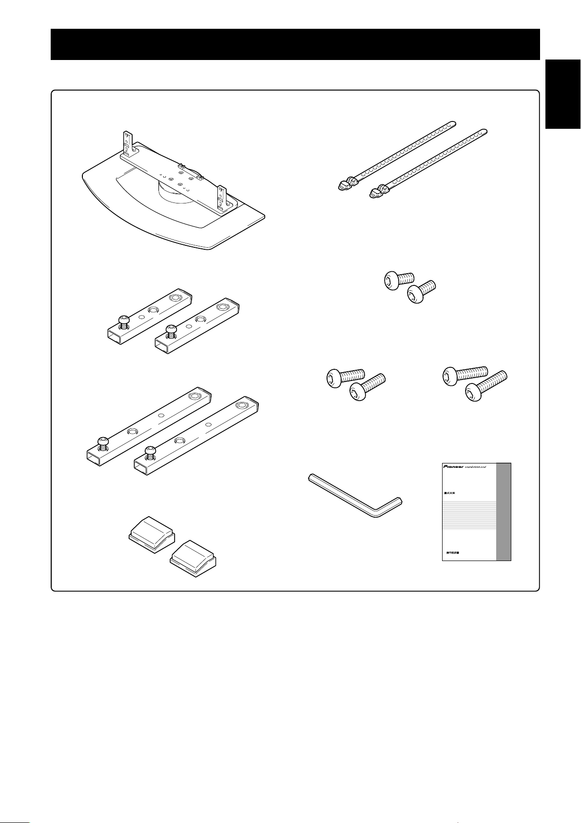
同梱された部品の確認
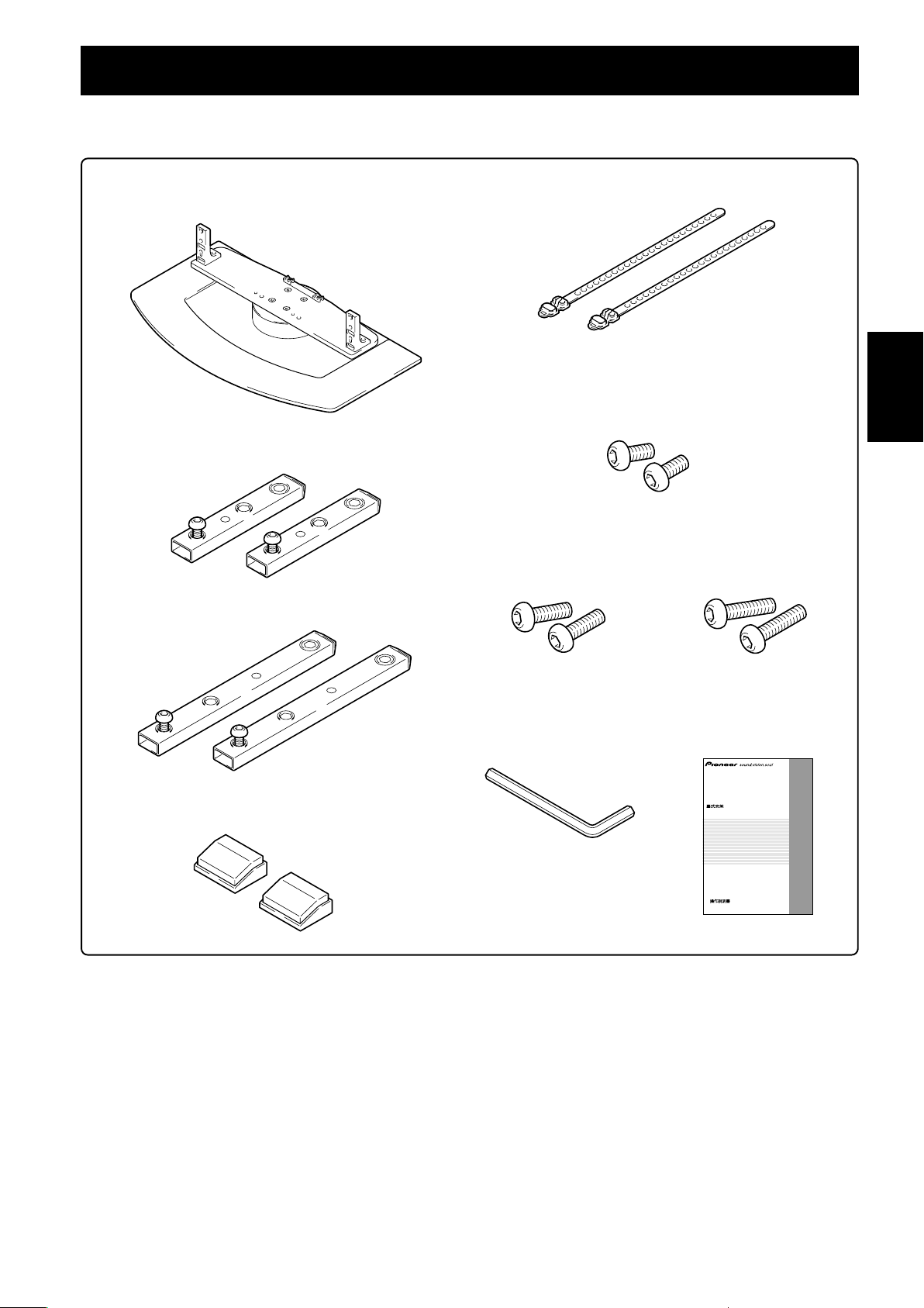
組み立て・設置の前に同梱された部品を確認してください。
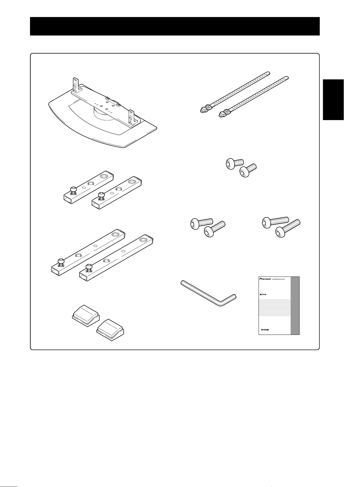
テーブルトップスタンド本体× 1
支柱 S× 2
[短い支柱]
支柱 L×2
[長い支柱]
ケーブルバインダー× 2
取付ネジ 1(M8 × 20mm:シルバー)× 2
[支柱、テーブルトップスタンド本体固定用]
取付ネジ
2
(M8 × 30mm:黒)× 2
取付ネジ 3
(M8 × 40mm:黒)× 2
日本語
スペーサー × 2
六角レンチ× 1
(対辺寸法: 5mm)
取扱説明書(本書)×1
テーブルトップスタンド
Table top stand
Support de couverture de table
Tischgestell
Supporto di tavolo
Tafel staander
Soporte de mesa
PDK-TS04
取扱説明書
Operating instructions
Mode d’emploi
Bedienungsanleitung
Istruzioni per l’uso
Gebruiksaanwijzing
ucciones
Manual de instrucciones
3
Ja
Page 4
スタンドの組み立てかた
ご注意
必ず平坦なテーブルなどの上で取り付けをしてください。
ネジは穴に対して垂直に挿入し、必要以上に強く締め付けないで
ください。
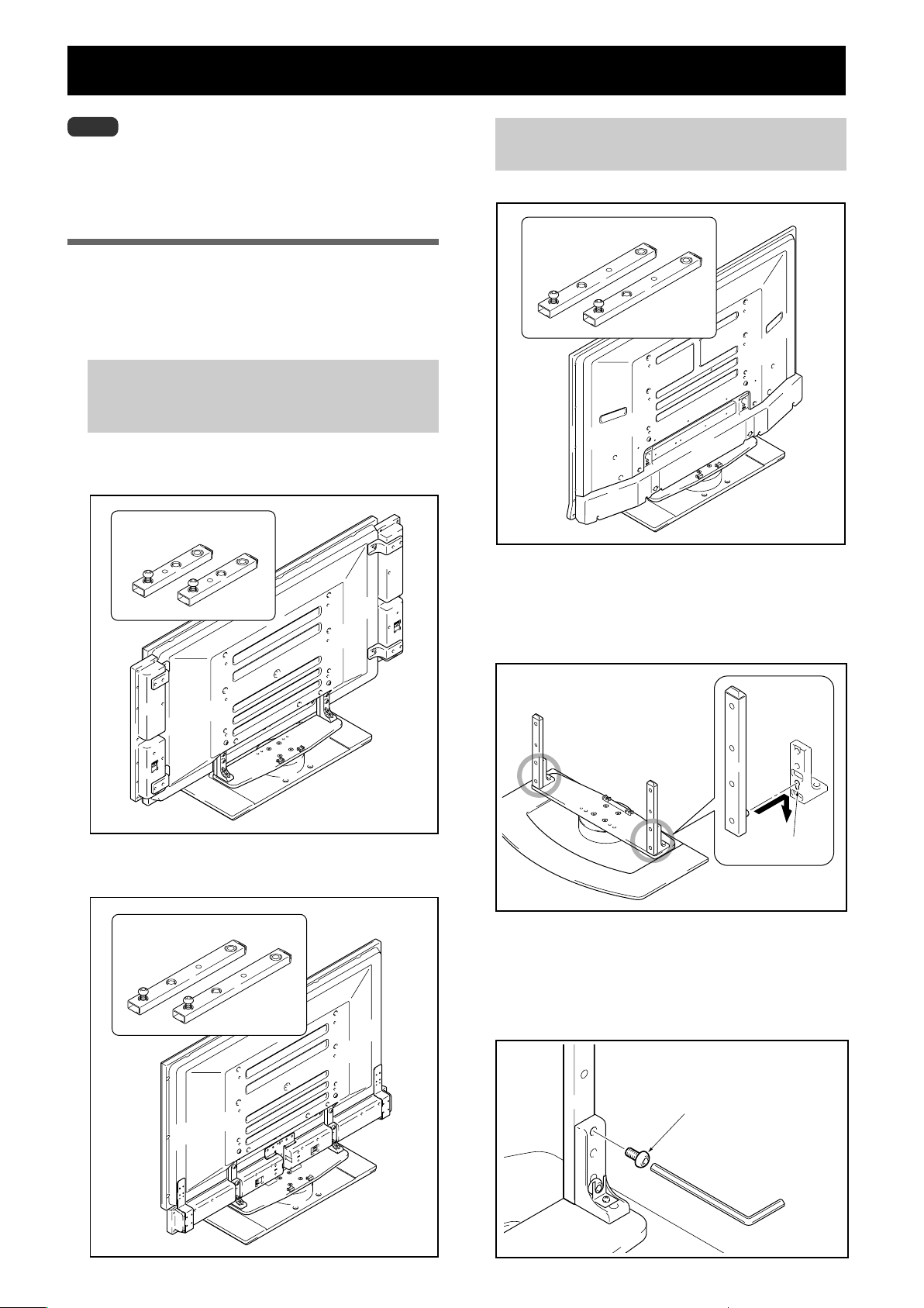
組み立て手順
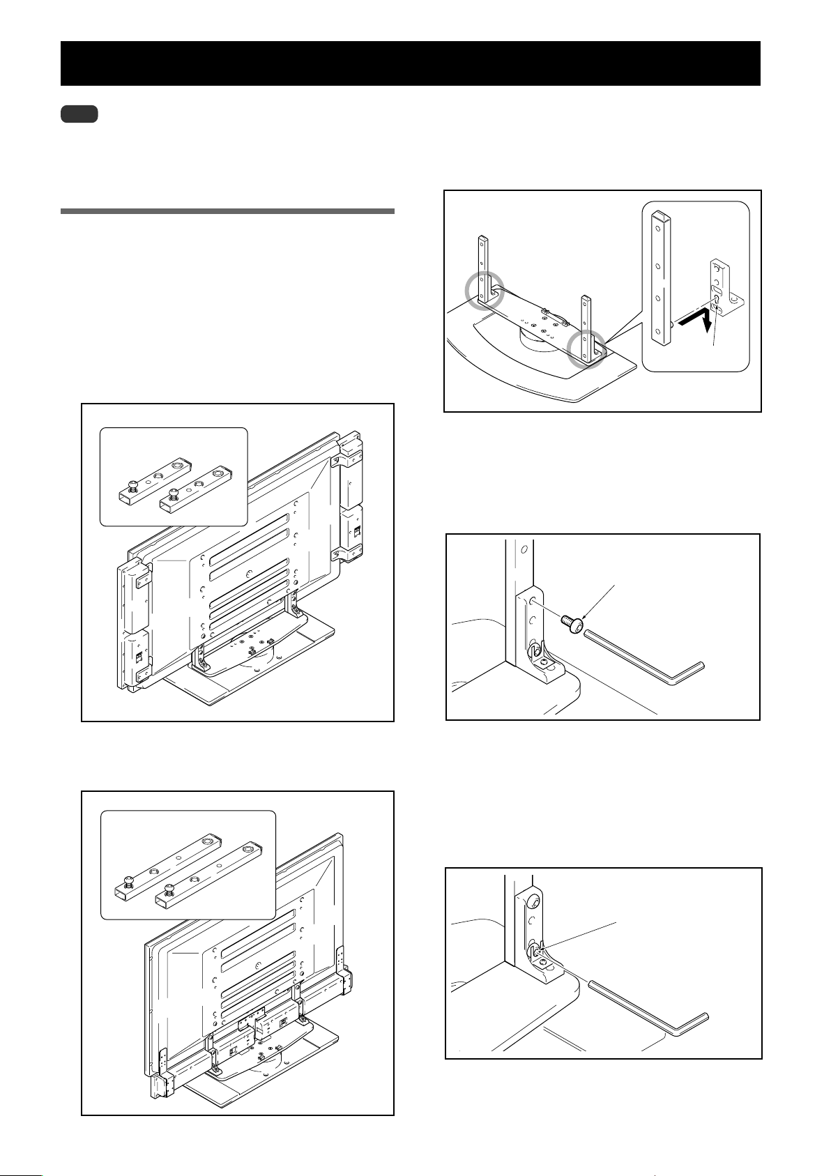
1 取り付ける支柱を選定する
下記を参照してお客様のお買い上げになったハイビジョン
プラズマテレビの種類や、スピーカーの設定に応じた支柱
を選んでください(2 種類のうち、1 種類を使います)。
お客様のお買い上げのハイビジョンプラズマテレビが
PDP-504HD / PDP-504HDV
PDP-434HD / PDP-434HDV の場合
本体両サイドにスピーカーを取り付ける場合
【使用する支柱:支柱 S】
使用する支柱:支柱 S
お客様のお買い上げのハイビジョンプラズマテレビが
PDP-434BX / PDP-434TX の場合
【使用できる支柱は支柱 L のみです】
使用する支柱:支柱 L
本体下側にスピーカーを取り付ける場合
【使用する支柱:支柱 L】
使用する支柱:支柱 L
2 スタンドに支柱を取り付ける
支柱にあらかじめ取り付けられているネジの頭をスタン
ドの支柱取付穴に入れ、下方向にスライドさせてくださ
い。
支柱取付穴
前面側
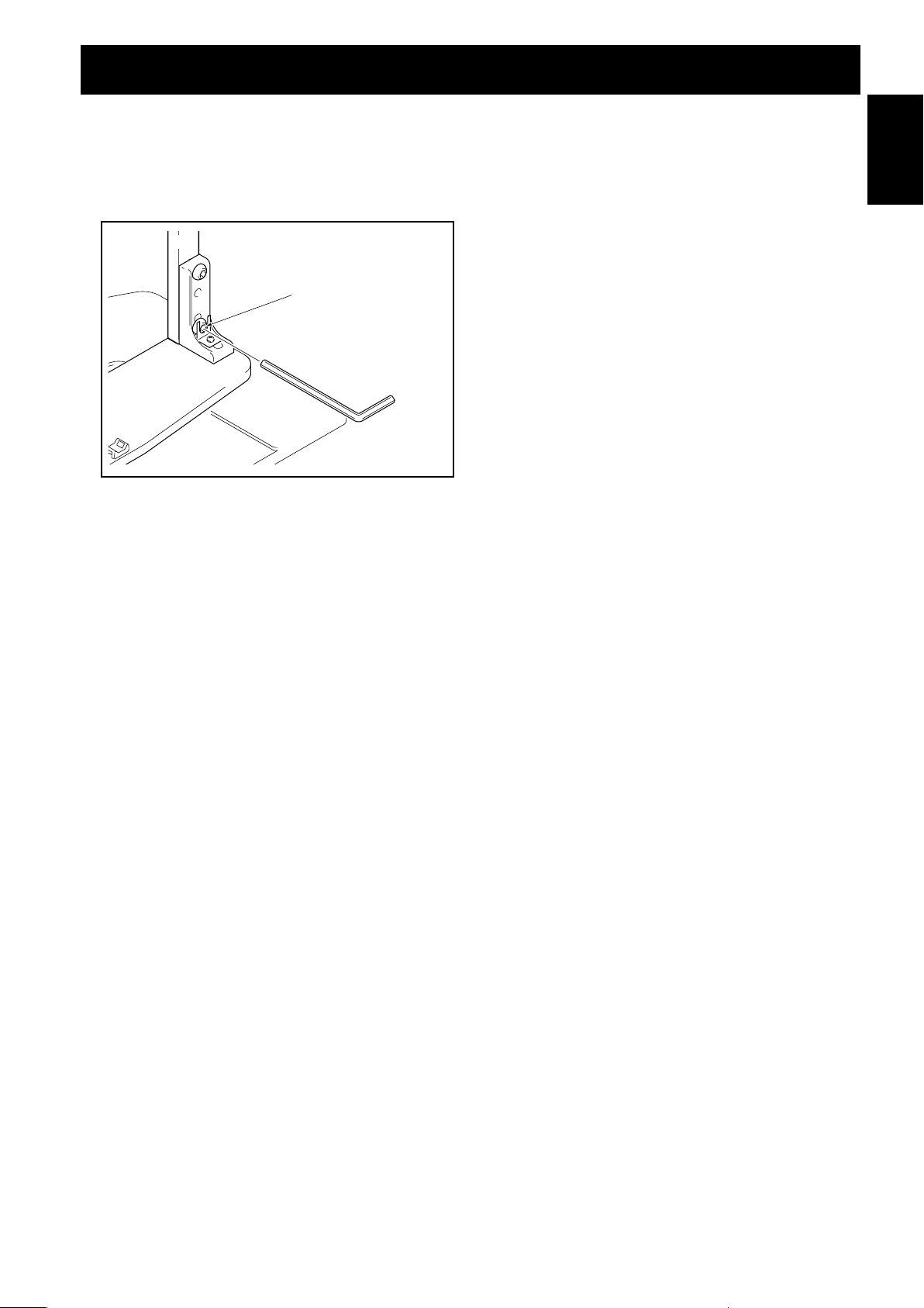
3 支柱とスタンドを取付ネジ 1 で固定する(左
右 2 カ所)
付属の六角レンチを使用して、裏側から 1 番上の穴へ垂
直に締め付けてください。
Ja
1
取付ネジ
4
Page 5
4 支柱にあらかじめ取り付けられているネジを増
し締めする(左右 2 カ所)
付属の六角レンチを使用して、支柱にあらかじめ取り付
けられているネジを増し締めしてください。
支柱にあらかじめ取り付け
られているネジを増し締め
する
スタンドの組み立てかた
日本語
5 取り付けたネジがしっかり締めつけられている
か、再度確認してください。
5
Ja
Page 6
ハイビジョンプラズマテレビの取り付けかた
ハイビジョンプラズマテレビは質量が50型モデルで約
40kg、43 型モデルで約 30kg あり、奥行きがなく不
注意
安定なため、取り付けおよび設置は必ず2人以上で行っ
てください。
ご注意
必ず平坦で安定した場所で取り付けをしてください。
ネジは穴に対して垂直に挿入し、必要以上に強く締め付けないで
ください。
『スタンドの組み立てかた』の手順を参照して、お客様のお買い上
げになったハイビジョンプラズマテレビの種類やスピーカーの設定
に応じた支柱が確実に取り付いていることを確認してください。
取り付け手順
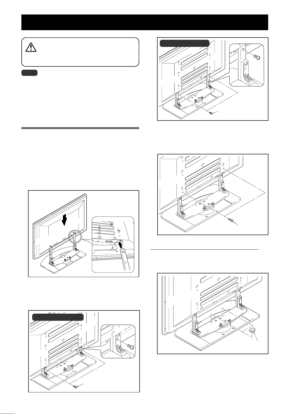
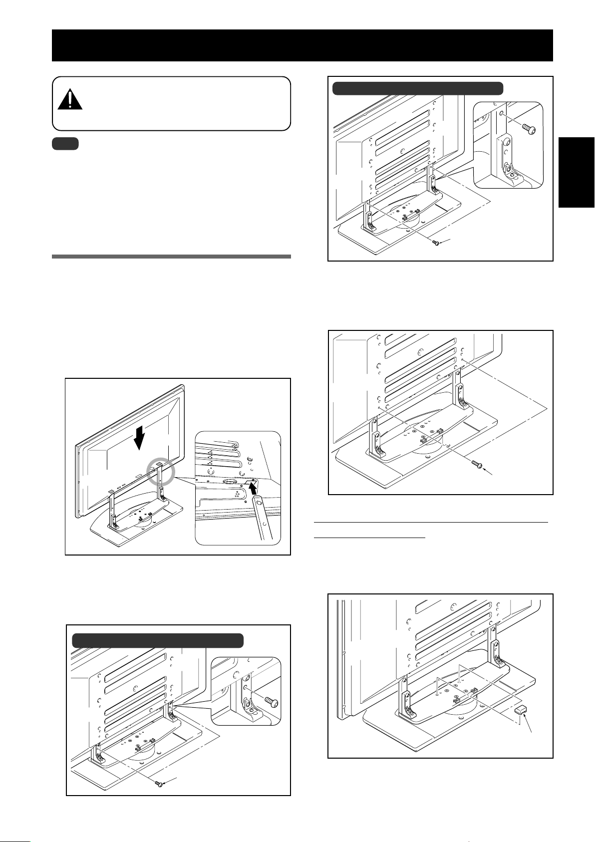
1 ハイビジョンプラズマテレビをスタンドに取り
付ける
ハイビジョンプラズマテレビの下側中央の凹部にスタン
ドの支柱を合わせて、垂直にゆっくり挿入してください。
スタンドの支柱をハイビジョンプラズマテレビのスタンド
挿入口以外の部分に当てないように注意してください。
本体裏面や端子にキズを付けたり、変形させる危険があり
ます。
イラスト:支柱L使用時
取付ネジ 2
3 取付ネジ 3 でハイビジョンプラズマテレビを
固定する
付属の六角レンチを使用して固定してください。
ハイビジョンプラズマテレビ
下部と支柱を図のように合わ
せる
2 取付ネジ 2 でハイビジョンプラズマテレビを
固定する
付属の六角レンチを使用して固定してください。
イラスト:支柱 S 使用時
取付ネジ 3
本体下側にスピーカーを取り付ける場合のみ
4 スペーサーをはめ込む
スペーサーをスタンド回転台上の穴にはめ込みます。
スペーサー
Ja
5 スピーカーを取り付ける
スピーカーの取り付け手順は、ハイビジョンプラズマテ
取付ネジ 2
6
レビに付属されている取扱説明書を参照してください。
Page 7
ラックなどに設置する場合
ハイビジョンプラズマテレビを取り付けた本製品をラックな
どに移動、設置する場合は、下記の点にご注意ください。
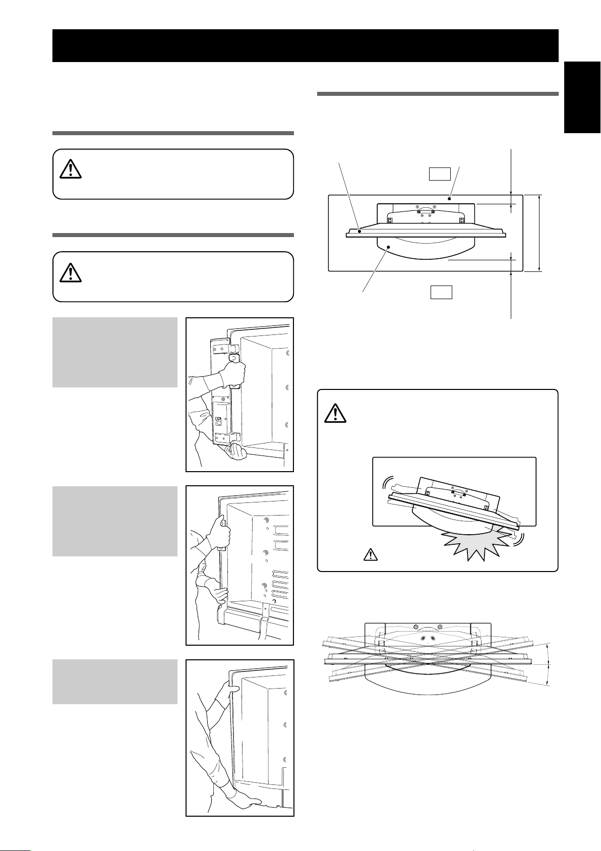
移動時のご注意
数メートルを超える移動をする際は、先にスピーカーを
取り外し、次にハイビジョンプラズマテレビ本体もスタ
注意
ンドから取り外し、別々に移動してください。
ラックなどに設置する際のご注意
ラックなどに設置する際は、ハイビジョンプラズマテレ
ビの下部と裏側の取っ手を持ってください。スピーカー
を持つと変形、破損の原因となります。
注意
ハイビジョンプラズマテレビ
PDP-504HD / PDP-504HDV
PDP-434HD / PDP-434HDV
の両サイドにスピーカーを設
置する場合
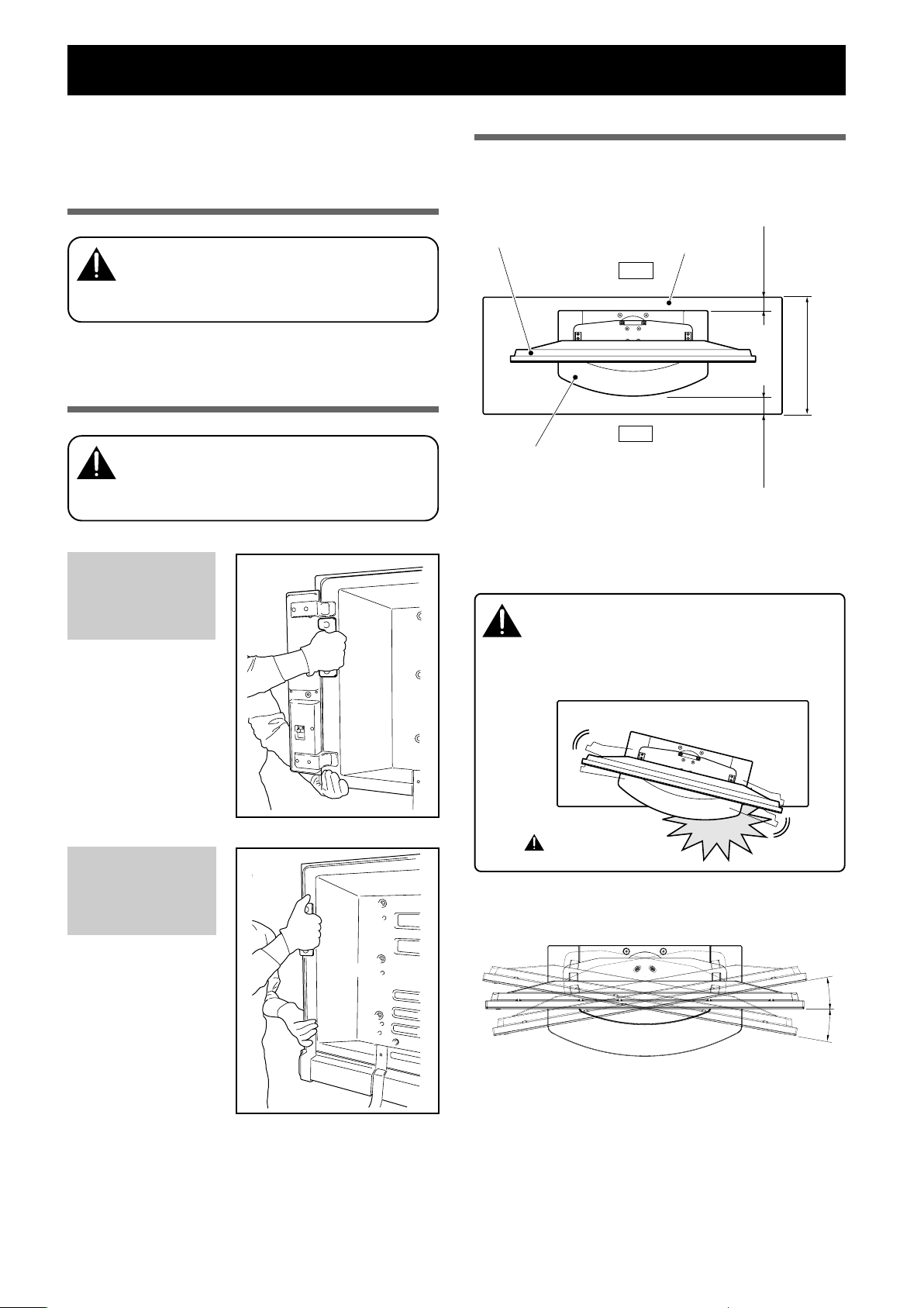
設置上のご注意
テーブルトップスタンドの前側および後側は、必ず下図の指
示以上のスペースを確保して設置してください。
ハイビジョンプラズマテレビ
テーブルトップスタンド
ただし上記のスペースを確保できないラックを使用する場合
は、できるだけラックを壁に寄せて前側のスペースを優先さ
せてください。
後側
前側
ラック
10mm 以上
30mm 以上
ラック奥行き寸法
430mm 以上推奨
日本語
ハイビジョンプラズマテレビ
の下部と取っ手を持ってくだ
さい。
ハイビジョンプラズマテレビ
PDP-504HD / PDP-504HDV
PDP-434HD / PDP-434HDV
の下側にスピーカーを設置す
る場合
ハイビジョンプラズマテレビ
の下部と取っ手を持ってくだ
さい。
ハイビジョンプラズマテレビ
PDP-434BX / PDP-434TX
の場合
スタンドがラックからはみ出すと、破損や転倒など思
回転させる時は、周囲の壁や物に注意してゆっくり動
注意
回転角度
わぬ事故の原因となります。
かしてください。
はみ出すと危険です。
10˚
10˚
本モデルには取っ手がありま
せん。
ハイビジョンプラズマテレビ
本体の横と下部を持ってくだ
さい。
7
Ja
Page 8
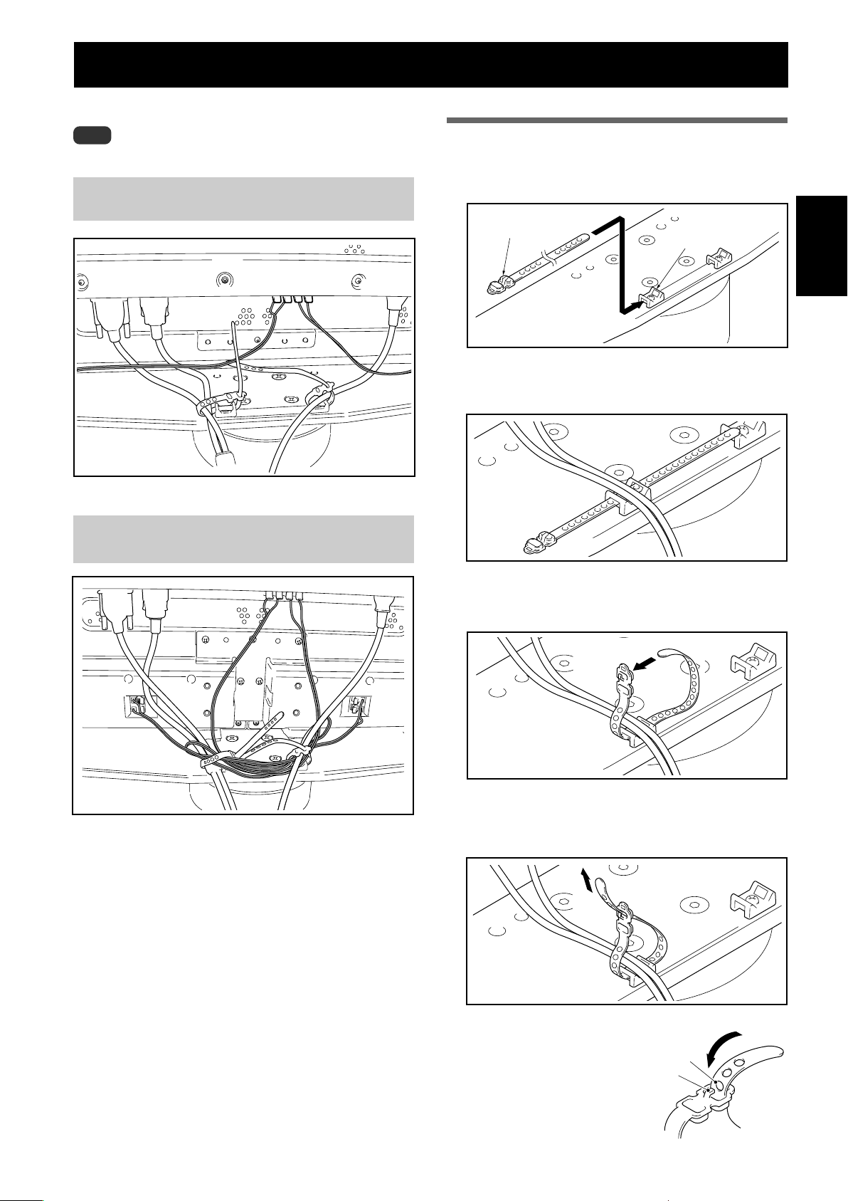
ケーブル処理のしかた
付属のケーブルバインダーを使用して、ケーブル類をまとめ
てください。
ご注意
ケーブルの根元に力が加わらないように注意してください。
ハイビジョンプラズマテレビ
PDP-504HD/PDP-504HDV/PDP-434HD/
PDP-434HDVの両サイドにスピーカーを設置する場合
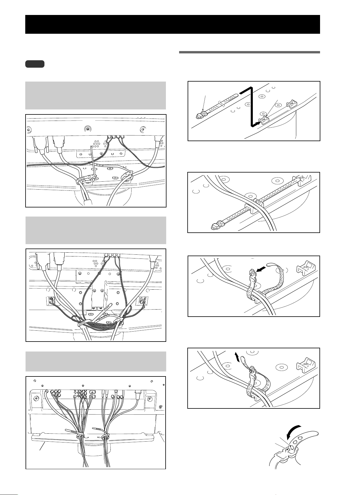
ケーブルバインダーの使いかた
1 スタンドの回転台上のケーブルバインダーホル
ダーにケーブルバインダーを通す
ケーブルバインダー
ケーブルバインダー
ホルダー
2 ケーブル類をまとめて、ケーブルバインダー上
に置く
ハイビジョンプラズマテレビ
PDP-504HD/PDP-504HDV/PDP-434HD/
PDP-434HDV の下側にスピーカーを設置する場合
ハイビジョンプラズマテレビ
PDP-434BX / PDP-434TX の場合
3 ケーブルバインダーの先端を穴に通す
4 ケーブルバインダーの先端をひっぱり、ケーブ
ルを固定する
Ja
ケーブルバインダーの外しかた
ケーブルバインダーの穴から固定
部をはずすとロックが外れます。
穴
固定部
8
Page 9
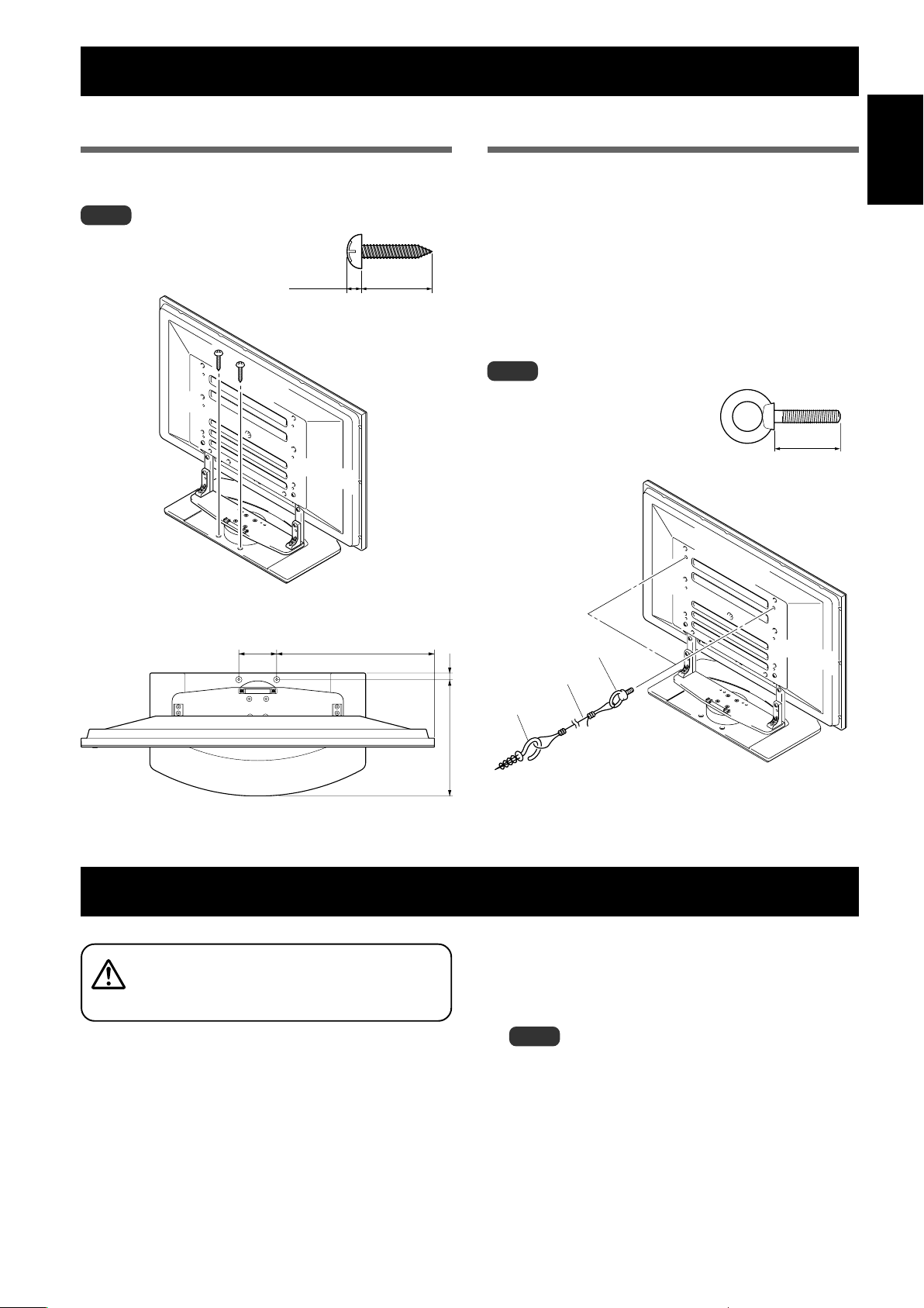
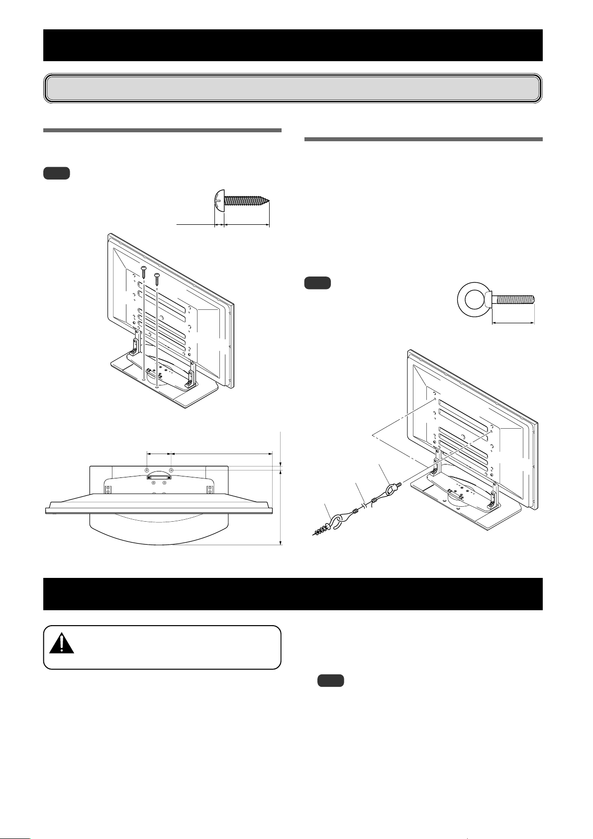
転倒防止(設置後は転倒防止の備えを必ず行ってください)
床に固定する方法
市販のネジを使って図のように固定してください。
ご注意
床に固定する際のネジは、呼び径6、
長さ 20mm 以上のものを使用し
てください。
5mm以下 20mm以上
壁を利用する方法(イラストは 43 型です)
1 ハイビジョンプラズマテレビに転倒防止用ボル
ト(フック)を取り付ける
2 壁、柱などの堅牢部に、丈夫なヒモまたはくさ
りでしっかりと固定する
左右対称に同様の作業を行ってください。
ヒモまたはくさりは、スタンド回転分の余裕をもって
長さを設定してください。
ご注意
フック、ヒモまたはくさり、取り付け具
は市販品をご使用ください。
推奨フック: 呼び径 8、
長さ 12 〜 15mm
12〜15mm
日本語
床固定ネジ取付位置(下図はスピーカーなし)
単位:mm
120
575(50型)
500(43型)
21
1 フック
2 ヒモまたはくさり
取付具
369
ハイビジョンプラズマテレビをスタンドから取り外す場合
ハイビジョンプラズマテレビをスタンドから取り外す場
合は、事故を防止するために以下の手順を必ず守ってく
注意
ださい。
1 あらかじめ平らな床などにハイビジョンプラズ
マテレビを寝かせるスペースを作り、キズおよ
び破損が生じないようにシートのようなものを
敷く。
3「ハイビジョンプラズマテレビの取り付けかた」
(6ページ)の手順 2、3 を参照し、黒色のネジ
(4 本)を外す。
ご注意
この時、シルバーのネジは外さないでください。支柱が外れて
転倒する危険があります。
4 ハイビジョンプラズマテレビの下側と取っ手を
持って、ゆっくり垂直に持ち上げる。
2 先にスピーカーを取り外す。
5 手順1で用意したシートの上に、画面を下にし
てゆっくり置く。
9
Ja
Page 10
仕 様
外形寸法 684(幅)× 351(高)× 390(奥行)mm【支柱 L 使用時】
質量 14.0kg
・上記の仕様および外観は、改良のため予告なく変更することがあります。
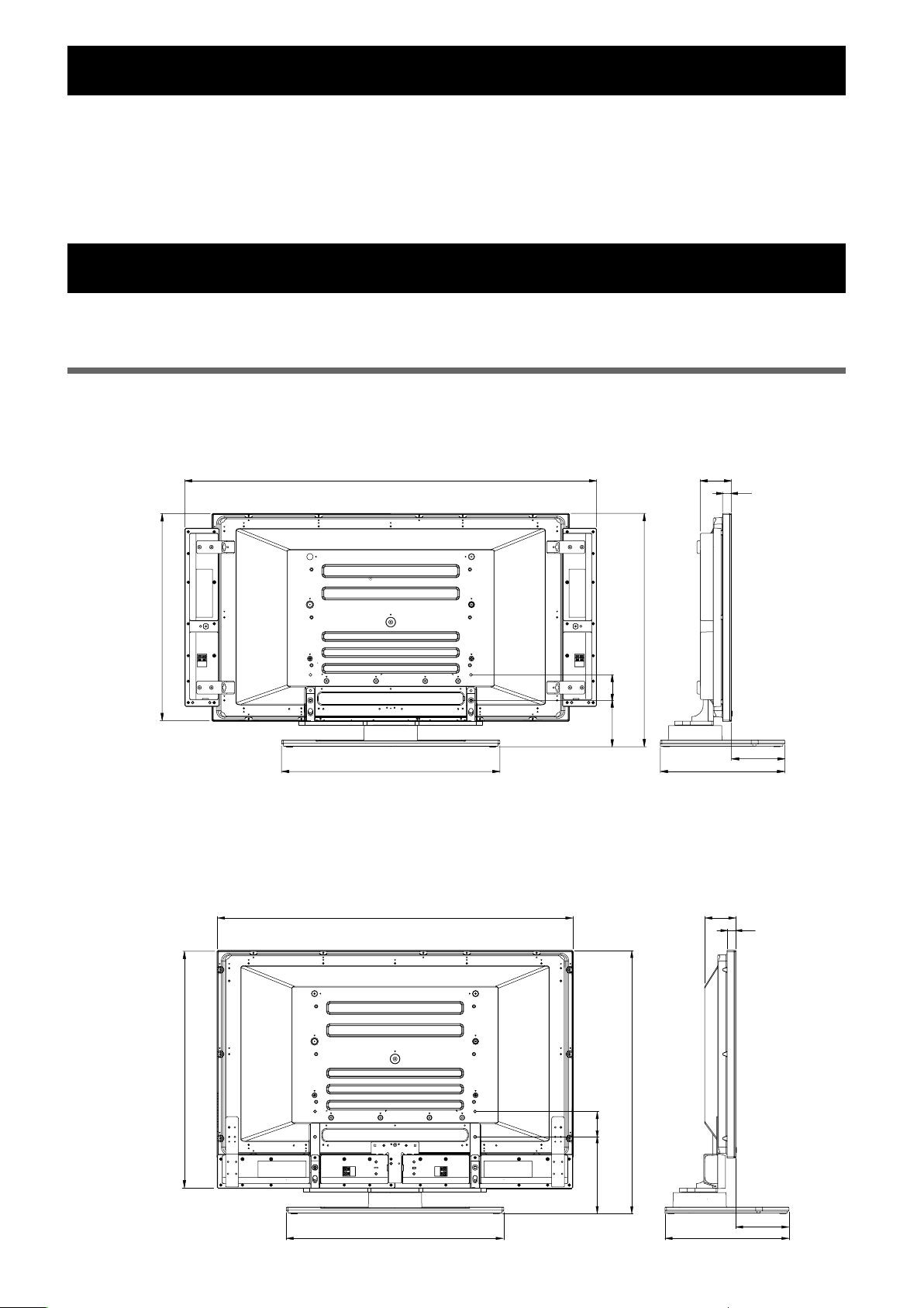
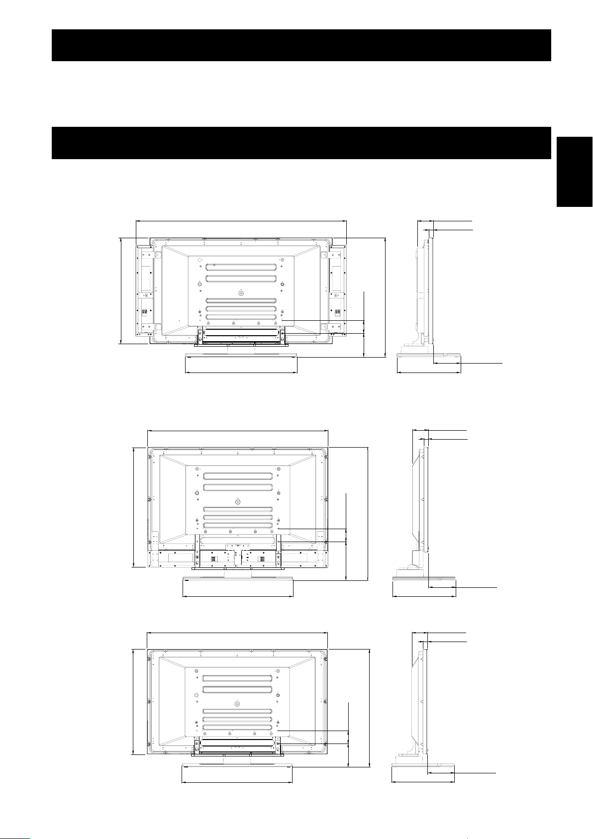
寸法図
単位:mm
PDP-504HD / PDP-504HDV / PDP-434HD / PDP-434HDV 取り付け時
本体両サイドにスピーカー取り付け時
1440 (PDP-504HD/PDP-504HDV)
1290 (PDP-434HD/PDP-434HDV)
98
28
737 (PDP-504HD/PDP-504HDV)
652 (PDP-434HD/PDP-434HDV)
816.5 (PDP-504HD/PDP-504HDV)
731.5 (PDP-434HD/PDP-434HDV)
145.5 80
684
※支柱 L 使用時には高さ 912.5(PDP-504HD / PDP-504HDV) / 827.5(PDP-434HD / PDP-434HDV)となります。
390
本体下側にスピーカー取り付け時
1270 (PDP-504HD/PDP-504HDV)
1120 (PDP-434HD/PDP-434HDV)
80
98
167
28
10
Ja
833 (PDP-504HD/PDP-504HDV)
748 (PDP-434HD/PDP-434HDV)
684
912.5 (PDP-504HD/PDP-504HDV)
827.5 (PDP-434HD/PDP-434HDV)
241.5
390
167
Page 11
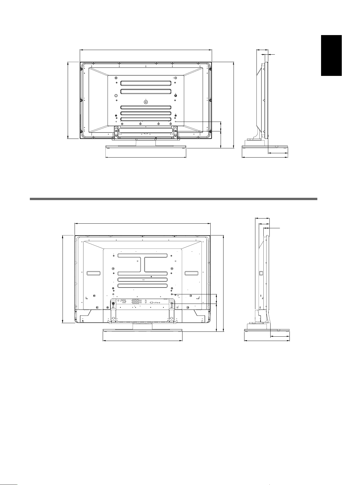
スピーカーなし
1270 (PDP-504HD/PDP-504HDV)
1120 (PDP-434HD/PDP-434HDV)
737 (PDP-504HD/PDP-504HDV)
652 (PDP-434HD/PDP-434HDV)
816.5 (PDP-504HD/PDP-504HDV)
731.5 (PDP-434HD/PDP-434HDV)
145.5 80
684
※支柱 L 使用時には高さ 912.5(PDP-504HD / PDP-504HDV) / 827.5(PDP-434HD / PDP-434HDV)となります。
98
28
390
日本語
167
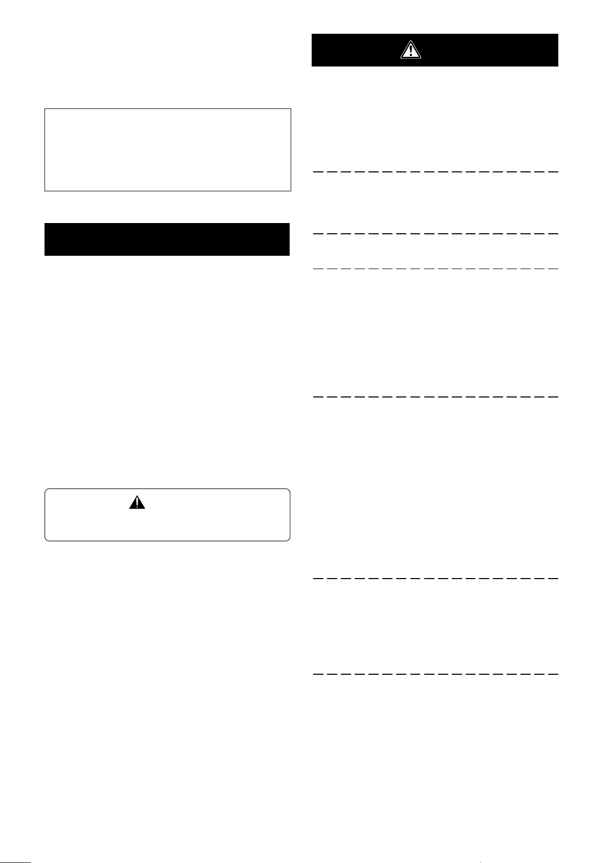
PDP-434BX / PDP-434TX 取り付け時
1168
753
684
80
241.5
827.5
122.5
91.6
390
50.6
165
2003パイオニア株式会社 禁無断転載
11
Ja
Page 12
Thank you for buying Pioneer’s product.
Please read through the Operating Instructions to learn how
to operate your model safely and properly.
Please be advised to keep the Operating Instructions in
your place for future reference.
Installation
¶ Consult your dealer if you encounter any difficulties
with this installation.
¶ Pioneer is not liable for any damage resulting from
improper installation, improper use, modification, or
natural disasters.
Cautions
This product is a table top stand exclusively designed for
plasma displays (PDP-504HD / PDP-5040HD / PDP-504HDE /
PDP-504HDG / PDP-434HD / PDP-4340HD /PDP-434HDE /
PDP-434HDG / PRO-1110HD / PRO-910HD) from Pioneer.
Note that it is not designed for use with any other equipment. For further information, please contact the store where
you purchased your display.
Do not install or modify the product other than specified.
Do not use this stand for a plasma display other than those
designated and do not modify it or use it for other purposes.
Contents
Cautions ................................................................. 12
Checking the Enclosed Parts................................ 13
Assembling the Stand .......................................... 14
Attaching the Plasma display .............................. 15
Installing the Product on a Rack etc. ................... 16
Preparing the Cables............................................. 17
Preventing Equipment from Falling Over ........... 18
Detaching the Plasma Display from the Stand .. 18
Specifications ........................................................ 19
Dimensions Diagram ............................................ 19
CAUTION
This symbol refers to a hazard or unsafe practice which
can result in personal injury or property damage.
Improper installation is extremely dangerous because it
may result in it falling over or other accident.
Installation Location
• Select a location that is strong enough to support the
weight of the stand and the displays.
• Make sure the installation location is a level, flat, and
stable surface and take proper precautions when installing it to make sure its weight is evenly distributed.
• Do not install it outdoors, at a hot spring, or near a beach.
• Do not install the stand where it may be subjected to
vibration or shock.
Assembling and Installation
• Assemble the stand in accordance with the assembly
instructions and securely attach all screws at the
designated locations.
There have been cases where unforeseen accidents
such as the equipment breaking or falling over
occurred after the installation of the display because
the stand was not installed as instructed.
• The display must always be installed by two or more
people to assure it is installed safely.
• Before installation, turn off the power for the display
and peripheral devices then remove the power cord
plug from the power outlet.
12
En
This product rotates 10° to the left and right.
Do not place objects within the range of rotation of this
product and the plasma display. Install this product so that
during routine use or when it is rotated, it does not protrude
from the rack or other location it has been installed. Failure
to do so could cause unforeseen accidents such as the
equipment breaking or falling over (see page 16).
Prevent accidents caused by the product falling over by
taking reliable measures to prevent it from falling over (see
Page 18).
Page 13
Checking the Enclosed Parts
Check to make sure that you have all the enclosed parts before assembly and installation.
Table top stand x 1
Support columns S x 2
[short columns]
Support columns L x 2
[long columns]
Cable binders x 2
Installation screws 1 (M8 x 20 mm: silver) x 2
[used to anchor the support columns and the table top stand]
Installation screws 2
(M8 x 30 mm: black) x 2
Installation screws 3
(M8 x 40 mm: black) x 2
English
Spacers x 2
Hexagonal wrench x 1
(Diagonal size: 5 mm)
Operating instructions
(this document) x 1
テーブルトップスタンド
Table top stand
Support de couverture de table
Tischgestell
Supporto di tavolo
Tafel staander
Soporte de mesa
PDK-TS04
取扱説明書
Operating instructions
Mode d’emploi
Bedienungsanleitung
Istruzioni per l’uso
Gebruiksaanwijzing
ucciones
Manual de instrucciones
13
En
Page 14
Assembling the Stand
Note
Always assemble it on a flat table etc.
Insert the screws in the holes vertically and do not tighten
them with more force than necessary.
Assembly Procedure
1 Select the support columns to attach.
Select the support columns according to the type of
plasma display that you have purchased and to the
speaker settings with reference to the following
stipulation. Note that only one of the two types of
available support columns should be used.
When installing speakers on both sides of the
plasma display
[Support column used: support column S]
Support column used:
support column S
2 Attaching the support columns to the stand.
Insert the head of the screw in the support column into
the hole for the support column in the stand and then
slide it downward.
Support column
attachment hole
Front side
3 Attach the support column to the stand
with the attachment screws 1 on the left
and right of the stand.
Use the enclosed hexagonal wrench to vertically tighten
it in the top hole from the rear.
When installing speakers at the bottom of the
plasma display
[Support column used: support column L]
Support column used:
support column L
Attachment screw 1
4 Fully tighten two screws on left and right
of stand which have been loosely screwed
into stand.
Use the provided hexagonal wrench to fully tighten the
attachment screws which have been loosely screwed in
on the left and right sides of the stand.
Tighten the two screws
which have already
been screwed into the
stand.
14
En
5 Reconfirm that the attached screw is
firmly tightened.
Page 15
Attaching the Plasma Display
The weight of a 50 inch plasma display is about 40 kg
(88 lbs), that of a 43 inch model is about 30 kg (66 lbs),
Caution
Note
Be sure to install it on a flat stable location.
Insert the screws in the holes vertically and do not tighten
Make sure that you install the support columns reliably
they have no depth, and are unstable. Therefore, at
least two people must assemble and install them.
them with more force than necessary.
according to the type of plasma display you have purchased and the speaker settings with reference to the
procedure in, Assembling the Stand.
Attachment Method
1 Attaching the plasma display to the stand.
Fit the stand’s support columns into the slots in the center of
the bottom of the plasma display then slowly insert them
directly into the slots. Be extremely careful not to insert the
support columns of the stand into any part of the plasma
display other than the stand insertion slots. Note that doing
so might damage the plasma display panel or its ports or
result in the warping of the stand.
Illustration: when using support columns L
English
Attachment screw 2
3 Securing the plasma display with attach-
ment screws 3.
Secure them using the enclosed hexagonal wrench.
Line up the column
supports with the bottom
of the plasma display as
indicated in the accompanying diagram.
2 Securing the plasma display with attach-
ment screws 2.
Secure them using the enclosed hexagonal wrench.
Illustration: when using support columns S
Attachment
screw 3
Only when attaching speakers at the bottom
of the plasma display
4 Inserting the spacers.
Insert the spacers in the holes on the rotating platform
of the stand.
Attachment screw 2
5 Attaching the speakers.
Refer to the operating instructions for the speaker for
the installation method.
Spacer
15
En
Page 16
Installing the Product on a Rack etc.
Be sure to observe the following precautions when moving
or installing this product with a plasma display into a rack or
other enclosure.
Precautions when moving
When moving the product more than a few meters,
first remove the speaker, then remove the plasma
Caution
display from the stand and move the speaker, plasma
display, and stand separately.
Precautions when installing in a rack
or other enclosure
When installing in a rack or other enclosure, hold the
plasma display by the handles located on the rear
Caution
When installing
speakers on both
sides of the plasma
display
Hold the plasma display
by its handles and from
the bottom.
and bottom of the plasma display. If you hold the
speakers, they may be damaged or twisted.
Installation precautions
Make sure that you always secure a space at least as large
as that shown in the following diagram in front of and
behind the table top stand.
Plasma display
Back
Front
Table top stand
But when using a rack for which the aforementioned
spaces cannot be secured, place the rack as close to a wall
as possible and give priority to securing the space in front.
If the stand protrudes from the rack, it could cause
unforeseen accidents such as the equipment break-
Caution
ing or falling over.
When rotating, take care not to allow the display
to bump into walls or surrounding objects.
Rack
Min. 10 mm
(13/32 inch)
Min. 30 mm
(1-3/16 inch)
Depth of the rack
430 mm (16-15/16 inch)
or more recommended
When installing
speakers at the
bottom of the
plasma display
Hold the plasma display
by its handles and from
the bottom.
16
En
Protrusion is dangerous.
Angle of rotation
10˚
10˚
Page 17
Preparing the Cables
Use the enclosed cable binders to bind the cables.
Note
Be very careful not to apply force to the bases of the cables.
When installing speakers on both sides of the
plasma display
Using the cable binders
1 Passing a cable binder though the cable
binder holder on the top of the rotating
platform of the stand.
Cable binder
Cable binder holder
2 Gathering cables and placing them on the
cable binder.
English
When installing speakers at the bottom of the
plasma display
3 Passing the cable binder through the hole
on its end.
4 Pulling the end of the cable binder to
secure the cables.
Removing a cable binder
If the secured part is removed
from the cable binder hole, it is
unlocked.
Hole
Secured
part
17
En
Page 18
Preventing Equipment from Falling Over
After installing the stand, be sure to take measures so that the equipment will not fall over.
Stabilizing on the floor
Stabilize the equipment as shown in the diagram using
screws that are available on the market.
Note
To stabilize the equipment on the
floor use screws that have a
nominal diameter of 6 and that are
at least 20 mm (25/32 inch) long.
Max. 5 mm
(0.2 inch)
Min. 20 mm
(25/32 inch)
Using a wall for stabilization
(43 inch display model in the figure)
1 Attaching falling prevention bolts (hooks)
to the plasma display.
2 Using strong cords or chains to firmly
stabilize it to a wall, pillar, or other sturdy
element.
Perform this work in the same way on the left and
right sides.
The length of the cords or chains used must be long
enough to allow the stand to rotate freely.
Note
Use hooks, ropes, chains, and fittings
that are available on the market.
Recommended hook: Nominal diameter 8
Length 12 to 15 mm (15/32 inch)
12–15mm
(15/32 inch)
Angle of rotation: Without speakers
Unit: mm (inch)
* : 43 inch display model
** : 50 inch display model
120
(4-23/32)
575 (22-21/32)*
500 (19-11/16)**
21 (13/16)
1 Hook
2 Cord or chain
Fitting
369 (14-17/32)
Detaching the Plasma Display from the Stand
To remove the plasma display from the stand, be sure
to always follow the procedure described below to
Caution
prevent accidents
1 First clear a space on a flat floor etc. where
you can lay the plasma display flat, then
cover the clear space with a sheet or other
material to protect it from scratches or
other damage.
2 Remove the speakers.
3 Referring to steps 2 and 3 in Attaching the
Plasma Display (Page 15.), remove the
black screws (4 screws).
Note
At this time, do not remove the silver screws. If you do,
the column supports might slip out of place and fall over.
4 Holding the plasma display by its handles
and from the bottom, lift the display vertically.
5 Place the screen slowly down onto the
cloth laid out in step 1.
18
En
Page 19
Specifications
External dimensions 684 (W) x 351 (H) x 390 (D) mm (26-15/16 (W) x 13-13/16 (H) x 15-11/32 (D) in.)
[When using the support columns L]
Weight 14.0 kg (30 lbs 14 oz)
• The above specifications and exterior may be modified without prior notice to improve the product.
Dimensions Diagram
Unit: mm (inch)
When installing speakers on both sides of the plasma display
1440 (56-11/16) [50 inch display model]
1290 (50-25/32) [43 inch display model]
80
(3-5/32)
98 (3-27/32)
28 (1-3/32)
English
737 (29-1/32) [50 inch display model]
652 (25-21/32) [43 inch display model]
684 (26-15/16)
• When using the support columns L, the height is 912.5 (35-15/16) [50 inch display model] / 827.5 (32-19/32) [43 inch display model].
When installing speakers at the bottom of the plasma display
1270 (50) [50 inch display model]
1120 (44-3/32) [43 inch display model]
748 (29-7/16) [43 inch display model]
833 (32-13/16) [50 inch display model]
684 (26-15/16)
Without speakers
1270 (50) [50 inch display model]
1120 (44-3/32) [43 inch display model]
816.5 (32-5/32) [50 inch display model]
145.5
731.5 (28-13/16) [43 inch display model]
(5-23/32)
390 (15-11/32)
98 (3-27/32)
28 (1-3/32)
80 (3-5/32)
912.5 (35-15/16) [50 inch display model]
827.5 (32-19/32) [43 inch display model]
241.5 (9-1/2)
390 (15-11/32)
98 (3-27/32)
28 (1-3/32)
167 (6-9/16)
167 (6-9/16)
80
(3-5/32)
737 (29-1/32) [50 inch display model]
652 (25-21/32) [43 inch display model]
684 (26-15/16)
• When using the support columns L, the height is 912.5 (35-15/16) [50 inch display model] / 827.5 (32-19/32) [43 inch display model].
816.5 (32-5/32) [50 inch display model]
145.5
731.5 (28-13/16) [43 inch display model]
(5-23/32)
390 (15-11/32)
167 (6-9/16)
Published by Pioneer Corporation.
Copyright © 2003 Pioneer Corporation.
All rights reserved.
19
En
Page 20
Nous vous remercions d’avoir procéder à l’achat d’un produit
Pioneer.
Veuillez lire attentivement ce Mode d’emploi pour savoir comment
opérer correctement et en toute sécurité votre modèle.
Nous vous conseillons de conserver soigneusement de Mode
d’emploi dans un endroit sûr et à proximité afin de pouvoir vous y
référer le cas échéant.
Installation
¶ Veuillez consulter votre revendeur si vous rencontrez des
difficultés lors de l’installation.
Pioneer n’assumera aucune responsabilité pour tout
dommage résultant d’une installation incorrecte, d’une
utilisation incorrecte, une modification de ce produit ou
encore de désastres naturels.
Attention
Ce produit est un support de couverture de table conçu
exclusivement pour les écrans d’affichage plasma fabriqué par
Pioneer : PDP-504HD / PDP-5040HD / PDP-504HDE / PDP504HDG / PDP-434HD / PDP-4340HD /PDP-434HDE / PDP-434HDG
/ PRO-1110HD / PRO-910HD. Veuillez noter que ce produit n’a pas
été conçu pour être utilisé avec d’autres équipements. Pour de
plus amples informations, veuillez contacter le vendeur où vous
avez acheté votre écran d’affichage.
Veuillez ne pas installer le produit d’une manière autre que celle
spécifiée ou modifier ce dernier. En outre, veuillez ne pas utiliser
ce support pour un écran d’affichage plasma autre que ceux pour
lesquels il a été conçu et ni le modifier ou l’utiliser à des fins
autres que celles pour lesquelles il a été conçu.
Table des matières
Attention .......................................................................... 20
Vérification des pièces contenues dans le carton
d’emballage ..................................................................... 21
Assemblage du support ................................................. 22
Installation et fixation de l’écran
d’affichage plasma .......................................................... 23
Installation du produit sur une étagère, etc. ................ 24
Préparation des câbles ................................................... 25
Prévenir le basculement et la chute de l’équipement ... 26
Démontage de l’écran plasma du support ................... 26
Spécificités....................................................................... 27
Diagramme indiquant les dimensions .......................... 27
ATTENTION
Ce symbole indique un danger ou une pratique dangereuse
risquant de compromettre la sécurité qui peut provoquer des
blessures ou des dégâts matériels.
Une installation incorrecte est extrêmement dangereuse car celleci peut provoquer le basculement du support ou un autre accident.
Emplacement d’installation
• Sélectionner un emplacement qui est assez solide pour
supporter le poids du support et de l’écran d’affichage.
• S’assurer que l’emplacement d’installation est bien plane et à
niveau et prendre toutes les précautions utiles et
indispensables lors de l’installation du support afin de veiller à
ce que le poids soit bien uniformément réparti.
• Ne pas installer le support à l’extérieur, à proximité d’une
source thermale ou sur la plage.
• Ne pas installer le support à un endroit où il pourrait être soumis
à des chocs ou à des vibrations.
Assemblage et installation
• Assembler le support conformément aux instructions
concernant l’assemblage et fixer solidement toutes les vis
aux endroits prévus à cet effet.
On a constaté des cas où des accidents imprévus sont
survenus (endommagement de l’équipement, chute, etc.)
après l’installation de l’écran d’affichage parque le support
n’avait pas été installé comme indiqué dans les instructions.
• L’écran d’affichage doit toujours être installé au moins par
deux personnes afin de veiller à ce qu’il soit installé en
toute sécurité.
• Avant de procéder à l’installation, mettre l’écran ainsi que
les équipements périphériques hors tension en coupant
l’alimentation, puis retirer la prise du câble d’alimentation
électrique de la prise femelle murale.
20
Cet article peut effectuer une rotation de 10° vers la gauche ou
vers la droite. Veuillez ne pas placer d’objets à l’intérieur de la
plage de rotation de cet article de telle sorte que durant une
utilisation habituelle ou lorsqu’on le fait tourner, il ne dépasse pas
de l’étagère ou de l’emplacement sur lequel il a été installé. Si on
n’observe pas cette précaution, il existe un risque d’accidents
imprévus comme un endommagement de l’équipement ou une
chute (Voir page 24).
Il convient de prévenir les accidents causés par la chute du produit
en prenant des mesures fiables pour éviter le basculement et la
chute (Voir page 26).
Fr
Page 21
Vérification des pièces contenues dans le carton d’emballage
Procéder à cette vérification afin de vous assurez que vous possédez bien toutes les pièces en questions avant de procéder à l’assemblage
et à l’installation du support.
Support de couverture de table x 1 unité
Colonnes de support S x 2 unités
(Colonnes courtes)
Colonnes de support L x 2 unités
(Colonnes longues)
Serre-câble x 2 unités
Vis d’installation 1 (M8 x 20 mm : argenté) x 2 unités
[Utilisées pour fixer les colonnes de support et le support de
couverture de table]
Vis d’installation 2
(M8 x 30 mm : noir) x 2 unités
Vis d’installation 3
(M8 x 40 mm : noir) x 2 unités
Français
Pièces d’écartement x 2 unités
Clé hexagonale (à six pans) x 1 unité
(Taille en diagonale : 5 mm)
Mode d’emploi
(ce document) x 1 exemplaire
テーブルトップスタンド
Table top stand
Support de couverture de table
Tischgestell
Supporto di tavolo
Tafel staander
Soporte de mesa
PDK-TS04
取扱説明書
Operating instructions
Mode d’emploi
Bedienungsanleitung
Istruzioni per l’uso
Gebruiksaanwijzing
ucciones
Manual de instrucciones
21
Fr
Page 22

Assemblage du support
Remarques
Toujours assembler le support sur une table bien plane, etc.
Introduire les vis à la verticale et ne pas serrer les vis plus qu’il
est nécessaire.
Procédure d’assemblage
1 Sélectionner les colonnes de support à fixer.
Sélectionner les colonnes de support selon le type d’écran
d’affichage plasma que vous avez acheté et les spécifications
des haut-parleurs en vous référant aux stipulations suivantes.
Veuillez noter que seulement l’un des deux types de colonnes
de support disponibles peuvent être utilisés.
Lors de l’installation des haut-parleurs des deux côtés
de l’écran plasma.
[Colonnes de support utilisées : colonnes de support S]
Colonnes de support utilisées :
colonnes de support S
2 Fixation des colonnes de support au support.
Insérer la tête de la vis dans la colonne de support à l’intérieur
de l’orifice réservé à la colonne de support dans le support et
faire coulisser ensuite vers le bas.
Orifice de fixation
de la colonne de
Face avant
support
3 Fixer la colonne de support au support avec les
vis d’installation 1 sur le côté gauche et sur le
côté droit du support.
Veuillez utiliser la clé hexagonale jointe pour visser à la
verticale les vis dans l’orifice supérieur à partir de l’arrière.
Lors de l’installation des haut-parleurs à la partie
inférieure de l’écran plasma.
[Colonnes de support utilisées : colonnes de support L]
Colonnes de support utilisées :
colonnes de support L
Vis d’installation 1
4 Bien serrer à fond les vis d’installation sur le
côté gauche et sur le côté droit du support qui
avaient été légèrement vissés dans le support.
Veuillez utiliser la clé hexagonale jointe pour bien visser à fond
les vis d’installation sur le côté gauche et sur le côté droit du
support qui avaient été légèrement vissés dans le support.
Resserrer les deux vis qui
avaient été déjà vissées
dans le support.
22
5 Revérifier que les vis d’installation sont bien
vissées à fond.
Fr
Page 23

Installation et fixation de l’écran d’affichage plasma
Le poids d’un écran plasma de 50 pouces est d’environ
40 kg, et celui d’un modèle de 43 pouces d’environ 30 kg.
Attention
Remarques
Toujours assembler l’écran plasma sur une surface table bien
Introduire les vis à la verticale et ne pas serrer les vis plus qu’il
Veiller à installer les colonnes de support de manière fiable
Ils n’ont pas de profondeur et sont instables.
plane et stable.
est nécessaire.
conformément au type d’écran plasma que vous avez acheté et
les spécifications des haut-parleurs en se référant à la procédure
indiquée à la section : Assemblage du support.
Méthode de fixation
1 Installation de l’écran plasma sur le support.
Placer les colonnes de support du support dans les fentes au
centre de la partie inférieure puis les insérer lentement et
directement dans les fentes. Veillez très soigneusement à ne
pas insérer les colonnes de support du support dans une
quelconque partie de l’écran d’affichage plasma autres que les
fentes prévues à cet effet. Veuillez noter que si vous faites
cela vous risquez d’endommager l’écran d’affichage ou les
entrées ou encore le support.
Illustration lorsque l’on utilise les colonnes de support L.
Vis d’installation 2
3 Fixer solidement l’écran d’affichage plasma
avec les vis d’installation 3.
Bien visser celles-ci au moyen de la clé hexagonale jointe avec
le support.
Français
Aligner les supports de
colonne avec la partie
inférieure de l’écran d’affichage
d’écran comme indiqué sur le
diagramme ci-joint.
2 Fixer solidement l’écran d’affichage plasma
avec les vis d’installation 2.
Bien visser celles-ci au moyen de la clé hexagonale jointe avec
le support.
Illustration lorsque l’on utilise les colonnes de support S.
Vis d’installation 3
Uniquement lorsque l’on fixe les haut-parleurs à la
base de l’écran d’affichage plasma
4 Insertion des pièces d’écartement.
Insérer les pièces d’écartement dans les orifices de la
plateforme rotative du support.
Vis d’installation 2
Pièce d’écartement
5 Mise en place des haut-parleurs.
Veuillez vous référer au mode d’emploi concernant les hautparleurs pour la méthode d’installation.
23
Fr
Page 24

Installation du produit sur une étagère, etc.
Veuillez respecter strictement les précautions suivantes lorsque
vous déplacez ou installez le produit avec un écran d’affichage
plasma sur une étagère ou un autre espace limité.
Précautions à respecter lors du
déplacement du produit
Lorsque l’on procède au déplacement de l’appareil sur
une distance supérieure à plusieurs mètres, veuillez
Attention
démonter tout d’abord les haut-parleurs. Puis démonter
également l’écran d’affichage plasma de son support et
transporter chaque partie séparément.
Précautions avant d’installer sur une étage
ou à un autre emplacement exigu
Lors de l’installation sur une étagère ou un endroit exigu,
tenir l’écran d’affichage plasma par les poignée situées à
Attention
Lors de l’installation
des haut-parleurs des
deux côtés de l’écran
plasma
Veuillez tenir l’écran
plasma par ces poignées
et par le dessous.
l’arrière et à la partie inférieure de l’écran. Si vous tenez
les haut-parleurs, ils risquent d’être endommagés ou
tordus.
Précautions d’installation
Veillez à toujours garantir un espace au moins aussi large que celui
indiqué sur le diagramme suivant à l’avant et à l’arrière du support
de couverture de table.
Ecran plasma
Arrière
Avant
Support
Lorsque vous utilisez une étagère, etc.. pour laquelle l’espace
susmentionné ne peut être garanti, veuillez placer l’étagère aussi
près que possible du mur et donner la priorité à l’espace situé en
avant.
Si le support dépasse en avant de l’étagère, ceci risque
de provoquer des accidents imprévus comme
Attention
l’endommagement de l’équipement ou une chute.
Lors d’une rotation du support, veuillez faire attention
de ne pas faire entrer en contact l’écran avec le mur ou
avec les autres objets environnants.
Etagère
10 mm mini
Profondeur de l’étagère
Nous recommandons 430 mm
30 mm mini
au minimum.
Lors de l’installation
des haut-parleurs à la
partie inférieure de
l’écran plasma
Veuillez tenir l’écran
plasma par ces poignées
et par le dessous.
24
Fr
Le dépassement est
dangereux.
Angle de rotation
10˚
10˚
Page 25

Préparation des câbles
Utiliser les serre-câbles pour regrouper les câbles.
Remarque
Veillez à ne pas mettre trop de force à la base de câbles.
Lors de l’installation des haut-parleurs des deux côtés de
l’écran d’affichage plasma
Utilisation des serre-câbles
1 Passer un serre-câble par le support de serre-
câble à la partie supérieure de la plate-forme
rotative sur le support.
Serre-câble
Support de serre-câble
2 Rassembler les câbles et les placer sur le serre-
câble.
Français
Lors de l’installation des haut-parleurs à la base de l’écran
d’affichage plasma.
3 Faire passer le serre-câble à travers le trou situé
à son extrémité.
4 Tirer sur l’extrémité du serre-câble pour
bloquer les câbles.
Retirer un serre-câble
Si la partie bloquée est enlevée
de l’orifice du serre-câble, celuici est débloqué.
Orifice
Partie bloquée
25
Fr
Page 26

Prévenir le basculement et la chute de l’équipement
Après avoir installé le support, veillez à prendre des mesures pour que l’équipement ne tombe pas.
Stabilisation sur la base
Veuillez stabiliser l’équipement comme indiqué sur le diagramme
en utilisant des vis vendues dans le commerce.
Remarque
Afin de stabiliser l’équipement sur
le sol, veuillez utiliser les vis ayant
un diamètre nominal de 6 mm et
une longueur d’au moins 20 mm.
5 mm maxi
20 mm mini
Utilisation d’un mur pour la stabilisation
du support.
(Modèle d’écran de 43 pouces comme indiqué sur la
figure)
1 Fixation des boulons empêchant la chute
(crochets) à l’écran plasma.
2 Utiliser des câbles solides ou des chaînes pour
stabiliser solidement le dispositif à un mur, un
pilier ou autres éléments stables.
Veuillez effectuer ces travaux de la même manière à
gauche et à droite.
La longueur des câbles ou des chaînes utilisés doit être
suffisante pour permettre au support de tourner sur sa
base librement.
Remarque
Utiliser des crochets, des chaînes et d’autres
dispositifs de fixation qui sont en vente dans
le commerce.
Crochet recommandé : Diamètre nominal 8,
longueur : de 12 à 15 mm.
12–15mm
Angle de rotation : sans les haut-parleurs
Unité : mm
575 (Ecran d'affichage 50 pouces)
500 (Ecran d'affichage 43 pouces)
120
21
Crochet
1
2 Câble ou chaîne
369
Attache
Démontage de l’écran plasma du support
Lorsque l’on démonte l’écran d’affichage plasma de son
support, veuillez respecter strictement la procédure
Attention
indiquée ci-dessous afin de prévenir les accidents.
1 Veuillez coucher au préalable l’écran
d’affichage plasma sur une surface plane
comme une plancher, etc. et garantir un espace
suffisant. Afin d’éviter d’égratigner l’écran ou
de l’endommager, placer une pièce de tissu
(drap, etc.) sur cette surface pour protéger
l’écran.
2 Retirer les haut-parleurs.
3 En vous référant aux opérations 2 et 3 décrites
dans ‘’ Installation et fixation de l’écran
d’affichage plasma ‘’ (p. 23), veuillez retirer les
4 vis noires.
Remar
que
A ce moment-là, n’enlevez pas la vis argentée car cela risquerait
de désolidariser les colonnes de support et de faire basculer
l’appareil.
4 Tout en tenant l’écran hexagonal par ses
poignées et par le fond, veuillez relever à la
verticale celui-ci.
5 Veuillez placer en douceur l’écran sur la surface
en tissu préparé à l’étape 1.
26
Fr
Page 27

Spécificités
Dimensions extérieures : 684 (largeur) x 351 (hauteur) x 390 (profondeur) mm (lors de l’utilisation de colonnes de support L)
Poids : 14,0 kg
• Les caractéristiques techniques indiquées ci-dessus et les dimensions extérieures peuvent êtres modifiées sans préavis en vue
d’améliorer le produit.
Diagramme indiquant les dimensions
Unité : mm
Lorsque l’on installe les haut-parleurs des deux côtés de l’écran d’affichage plasma
1440 (Ecran d'affichage 50 pouces)
1290 (Ecran d'affichage 43 pouces)
737 (Ecran d'affichage 50 pouces)
652 (Ecran d'affichage 43 pouces)
684
80
816,5 (Ecran d'affichage 50 pouces)
731,5 (Ecran d'affichage 43 pouces)
145,5
98
28
167
390
Français
• Lors de l’utilisation des colonnes de support L, la hauteur est de 912,5 mm (écran de 50 pouces) et de 827,5 mm (écran de 43 pouces).
Lorsque l’on installe les haut-parleurs à la base de l’écran d’affichage plasma
1270 (Ecran d'affichage 50 pouces)
1120 (Ecran d'affichage 43 pouces)
80
833 (Ecran d'affichage 50 pouces)
748 (Ecran d'affichage 43 pouces)
Sans les haut-parleurs
684
1270 (Ecran d'affichage 50 pouces)
1120 (Ecran d'affichage 43 pouces)
241,5
98
28
912,5 (Ecran d'affichage 50 pouces)
827,5 (Ecran d'affichage 43 pouces)
390
98
28
167
80
737 (Ecran d'affichage 50 pouces)
652 (Ecran d'affichage 43 pouces)
684
• Lors de l’utilisation des colonnes de support L, la hauteur est de 912,5 mm (écran de 50 pouces) et de 827,5 mm (écran de 43 pouces).
816,5 (Ecran d'affichage 50 pouces)
731,5 (Ecran d'affichage 43 pouces)
145,5
Publication de Pioneer Corporation.
© 2003 Pioneer Corporation.
Tous droits de reproduction et de traduction réservés.
390
167
27
Fr
Page 28

Wir danken Ihnen, dass Sie sich für den Kauf eines Produkts der
Firma Pioneer entschieden haben.
Bitte lesen die Bedienungsanleitung aufmerksam, um sich über
die sichere und richtige Bedienung Ihres Modells zu informieren.
Wir empfehlen Ihnen, die Bedienungsanleitung anschließend
sicher aufzubewahren, um Sie später im Bedarfsfalle zu Rate
ziehen zu können.
Installation
¶ Bitte setzen Sie sich mit Ihrem Händler in Verbindung, wenn
Sie auf Schwierigkeiten bei der Installation stoßen.
Die Firma Pioneer haftet nicht für Schäden, die auf falsche
Installation, auf inkorrekte Verwendung, auf vorgenommene
Veränderungen oder auf Naturkatastrophen zurückzuführen
sind.
Sicherheitshinweise
Dieses Produkt ist ein Tischständer, und er ist ausschließlich für
die Plasmadisplays der Firma Pioneer (PDP-504HD / PDP-5040HD
/ PDP-504HDE / PDP-504HDG / PDP-434HD / PDP-4340HD / PDP434HDE / PDP-434HDG / PRO-1110HD / PRO-910HD) bestimmt.
Bitte beachten Sie, dass er nicht für den Gebrauch mit einem
anderen Gerät vorgesehen ist. Bitte setzen Sie sich hinsichtlich
weiterer Informationen mit der Handelseinrichtung in Verbindung,
in der Sie Ihr Display gekauft haben.
Installieren Sie das Produkt nicht anders als angegeben und
nehmen Sie keine Änderungen am Produkt vor. Verwenden Sie
diesen Ständer nicht für ein anderes Plasmadisplay als für das, für
das es vorgesehen ist, verändern Sie ihn nicht und verwenden Sie
ihn nicht für andere Zwecke.
Inhalt
Sicherheitshinweise........................................................ 28
Überprüfen der mitgelieferten Teile .............................. 29
Montage des Ständers ................................................... 30
Montieren des Plasmadisplays ...................................... 31
Installieren des Produkts auf einem Gestell oder etwas
Ähnlichem
Verlegen der Kabel .......................................................... 33
Mittel zur Verhütung des Umstürzens.......................... 34
Demontieren des Plasmadisplays vom Ständer .......... 34
Technische Daten ............................................................ 35
Abbildungen zu den Abmessungen .............................. 35
Dieses Symbol kennzeichnet eine gefährliche oder riskante
Vorgehensweise, die zu eigenen Verletzungen, zu
Verletzungen anderer Personen oder zu Sachschäden führen
kann.
......................................................................... 32
Vorsicht!
Eine falsche Installation ist sehr gefährlich, da sie zum Umfallen
des Displays oder einem anderen Unfall führen kann.
Installationsort
• Wählen Sie für die Installation einen Ort, der stabil genug ist,
das Gewicht des Ständers und des Displays zu tragen.
• Vergewissern Sie sich, dass der Installationsort eine
waagerechte, ebene und stabile Fläche ist und treffen Sie beim
Installieren die richtigen Vorkehrungen, dass Sie sicher sein
können, dass das Gewicht gleichmäßig verteilt wird.
• Installieren Sie den Ständer nicht im Freien, in der Nähe einer
heißen Quelle oder in Strandnähe.
• Installieren Sie den Ständer nicht an Orten, an denen er
Vibrationen oder Stößen ausgesetzt ist.
Montage und Installation
• Montieren Sie den Ständer gemäß den
Montageanweisungen und befestigen Sie alle Schrauben
sicher an den jeweils vorgesehenen Positionen.
Es hat Fälle gegeben, in denen es nach der Installation des
Displays zu unvorhergesehenen Unfällen wie
beispielsweise einem Bruch oder zum Umfallen kam, weil
der Ständer nicht wie vorgeschrieben installiert wurde.
• Das Display muss stets von zwei oder mehr Personen
installiert werden, um zu sichern, dass es sicher installiert
wird.
• Schalten Sie das Display und periphere Geräte vor der
Installation aus und trennen Sie es bzw. sie durch
Herausziehen des Steckers aus der Steckdose vom Netz.
28
Ge
Dieses Produkt kann Drehungen um 10° nach links und nach
rechts ausführen.
Platzieren Sie keine Objekte im Drehbereich dieses Produkts und
des Plasmadisplays. Installieren Sie den Ständer so, dass er beim
normalen Gebrauch oder wenn er gedreht wird nicht aus dem
Gestell oder einem anderen Ort, an dem er installiert ist,
herausragt. Wenn Sie dies nicht tun, riskieren Sie
unvorhergesehene Unfälle wie beispielsweise das Zerbrechen
oder Umfallen des Displays (siehe Seite 32).
Beugen Sie Unfällen durch das Umfallen des Produkts vor, indem
Sie zuverlässige Maßnahmen treffen, die es vor dem Umfallen
bewahren (siehe Seite 34).
Page 29

Überprüfen der mitgelieferten Teile
Überprüfen Sie vor der Montage und Installation die mitgelieferten Teile auf Vollständigkeit.
Tischständer: 1
Stützsäulen S: 2 (kurze Säulen)
Stützsäulen L: 2 (lange Säulen)
Kabel-Fixierband: 2
Befestigungsschrauben 1 (M8 x 20 mm, silberfarben): 2
[zur Verankerung der Stützsäulen und des Tischständers]
Befestigungsschrauben 2
(M8 x 30 mm, schwarz): 2
Befestigungsschrauben 3
(M8 x 40 mm, schwarz): 2
Deutsch
Distanzstücke: 2
Sechskant-Stiftschlüssel: 1
(Diagonalgröße: 5 mm)
Bedienungsanleitung
(dieses Dokument): 1
テーブルトップスタンド
Table top stand
Support de couverture de table
Tischgestell
Supporto di tavolo
Tafel staander
Soporte de mesa
PDK-TS04
取扱説明書
Operating instructions
Mode d’emploi
Bedienungsanleitung
Istruzioni per l’uso
Gebruiksaanwijzing
ucciones
Manual de instrucciones
29
Ge
Page 30

Montage des Ständers
Hinweise
Montieren Sie den Ständer immer auf einem ebenen Tisch oder
etwas Ähnlichem.
Führen Sie die Schrauben vertikal in die vorgesehenen
Schraublöcher ein und ziehen Sie sie nicht mit mehr Kraft als
erforderlich an.
Montagevorgang
1 Wählen Sie die zu befestigenden Stützsäulen.
Wählen Sie die Stützsäulen entsprechend dem Typ des
Plasmadisplays, das Sie gekauft haben, und den
Lautsprecherpositionen unter Berücksichtigung der
nachfolgend genannten Bedingungen. Bitte beachten Sie, nur
einen der zwei Typen der mitgelieferten Stützsäulen zu
verwenden.
Installation der Lautsprecher an den beiden Seiten des
Plasmadisplays
[zu verwendende Stützsäule: Stützsäule S]
Zu verwendende Stützsäule:
Stützsäule S
2 Befestigen der Stützsäulen am Ständer.
Führen Sie den Kopf der Schraube in der Stützsäule in das
Loch für die Stützsäule im Ständer ein und lassen Sie sie dann
nach unten gleiten.
Befestigungsloch
für die Stützsäule
Vorderseite
3 Befestigen Sie die Stützsäulen mit den
Befestigungsschrauben 1 links und rechts am
Ständer.
Verwenden Sie den mitgelieferten Sechskant-Stiftschlüssel,
um die Schrauben von der Rückseite her im oberen Loch
vertikal festzuziehen.
Installation der Lautsprecher unterhalb des
Plasmadisplays
[zu verwendende Stützsäule: Stützsäule L]
Zu verwendende Stützsäule:
Stützsäule L
Befestigungsschraube 1
4 Ziehen Sie zwei Schauben links und rechts am
Ständer, die locker in den Ständer geschraubt
wurden, fest.
Verwenden Sie den mitgelieferten Sechskant-Stiftschlüssel,
um die Befestigungsschrauben, die links und rechts am
Ständer locker in den Ständer geschraubt wurden, richtig
festzuziehen.
Ziehen Sie die zwei
Schrauben, die bereits in
den Ständer geschraubt
wurden, fest.
30
Ge
5 Überzeugen Sie sich, dass die angebrachten
Schrauben richtig festgezogen sind.
Page 31

Montieren des Plasmadisplays
Das Gewicht eines 50-Zoll-Plasmadisplays beträgt etwa
40 kg und das eines 43-Zoll-Modells etwa 30 kg. Die
Plasmadisplays sind flach, das heißt, sie haben keine
Vorsicht!
Hinweise
Vergewissern Sie sich, dass Sie das Plasmadisplay an einem
Führen Sie die Schrauben vertikal in die Schraublöcher ein und
Vergewissern Sie sich, dass Sie die Stützsäulen unbedingt
Tiefe und sind somit instabil. Daher muss die Montage
und Installation von mindestens zwei Personen
vorgenommen werden.
ebenen und stabilen Ort installieren.
ziehen Sie sie nicht mit mehr Kraft als erforderlich fest.
entsprechend dem Typ des Plasmadisplays, das Sie gekauft
haben, und den Lautsprecherpositionen unter Berücksichtigung
der unter „Montage des Ständers“ beschriebenen
Verfahrensweise installieren.
Befestigungsmethode
1 Befestigen des Plasmadisplays am Ständer.
Passen Sie die Stützsäulen des Ständers den Öffnungen in
der Mitte unten am Plasmadisplay an und führen Sie sie dann
langsam direkt in die Öffnungen ein. Achten Sie bitte
unbedingt darauf, dass sie die Stützsäulen des Ständers nicht
in irgendeinen anderen Teil des Ständers einführen als in die
dafür vorgesehenen Öffnungen. Wenn Sie dies nicht
beachten, besteht die Gefahr, dass Sie das Bedienfels des
Plasmadisplays beschädigen oder seine Anschlussbuchsen
oder dass sich der Ständer verzieht.
Abbildung: Verwendung der Stützsäule L
Befestigungsschraube 2
3 Sichern des Plasmadisplays mit den
Befestigungsschrauben 3.
Ziehen Sie die Schrauben unter Verwendung des
mitgelieferten Sechskant-Stiftschlüssels an.
Deutsch
Bringen Sie die Stützsäulen
in Übereinstimmung mit
dem unteren Teil des
Plasamdisplays, wie es in
der zugehörigen Abbildung
dargestellt ist.
2 Sichern des Plasmadisplays mit den
Befestigungsschrauben 2.
Ziehen Sie die Schrauben unter Verwendung des
mitgelieferten Sechskant-Stiftschlüssels an.
Abbildung: Verwendung der Stützsäule S
Befestigungsschraube 3
Nur bei Installation der Lautsprecher unterhalb
des Plasmadisplays
4 Insetzen der Distanzstücke.
Setzen Sie die Distanzstücke in die Öffnungen an der DrehPlattform des Ständers ein.
Befestigungsschraube 2
Distanzstück
5 Befestigen der Lautsprecher.
Hinsichtlich der Installationsmethode für die Lautsprecher
ziehen Sie bitte die Bedienungsanleitung für die Lautsprecher
zu Rate.
31
Ge
Page 32

Installieren des Produkts auf einem Gestell oder etwas Ähnlichem
Beachten Sie bitte unbedingt die folgenden Sicherheitshinweise,
wenn Sie den Ständer mit einem Plasmadisplay fortbewegen oder
ihn in einem Gestell oder einem anderen Möbelstück installieren.
Sicherheitshinweise für das Fortbewegen
oder Transportieren
Wenn Sie den Tischständer mit dem Plasmadisplay und
den Lautsprechern mehr als ein paar Meter fortbewegen
Vorsicht!
oder transportieren wollen, dann entfernen Sie zunächst
die Lautsprecher und dann das Plasmadisplay vom
Tischständer und transportieren Sie anschließend
Lautsprecher, Plasmadisplay und Tischständer getrennt.
Sicherheitshinweise für das Installieren in
einem Gestell oder einem anderen
Möbelstück
Wenn Sie den Ständer mit den Lautsprechern und dem
Vorsicht!
Bei Installation der
Lautsprecher an den
beiden Seiten des
Plasmadisplays
Display in einem Gestell oder einem anderen Möbelstück
installieren, dann halten sie das Plasmadisplay an den
auf der Rückseite des Plasmadisplays befindlichen
Handgriffen und an der Unterseite des Plasmadisplays.
Wenn Sie das Ganze an den Lautsprechern halten, dann
können diese beschädigt oder verdreht werden.
Sicherheitshinweise für die Installation
Vergewissern Sie sich, dass Sie vor und hinter dem Tischständer
immer einen Mindestabstand absichern, wie er im folgenden
Diagramm angegeben ist.
Plasmadisplay
Rückseite
Vorderseite
Tischständer
Wenn jedoch ein Gestell verwendet wird, bei dem die oben
genannten Abstände nicht abgesichert werden können, dann
stellen Sie das Gestell so nahe wie möglich an eine Wand und
geben Sie der Absicherung des Abstands auf der Vorderseite die
Priorität.
Wenn der Ständer aus dem Gestell herausragt,
besteht die Gefahr, dass unvorhergesehene Unfälle
Vorsicht!
wie beispielsweise ein Zerbrechen oder ein Umstürzen
der Anlage.
Wenn Sie das Display drehen, dann achten Sie bitte
unbedingt darauf, dass es nicht an Wände oder andere
Objekte der unmittelbaren Umgebung stößt.
Gestell
Min. 10 mm
Tiefe des Gestells:
Min. 30 mm
Mind. 430 mm werden
empfohlen
Halten Sie das
Plasmadisplay an seinen
Handgriffen und von
unten her.
Bei Installation der
Lautsprecher
unterhalb des
Plasmadisplays
Halten Sie das
Plasmadisplay an seinen
Handgriffen und von
unten her.
Herausragen ist gefährlich!
Drehwinkel
10˚
10˚
32
Ge
Page 33

Verlegen der Kabel
Verwenden Sie die mitgelieferten Kabelbänder zum
übersichtlichen Verlegen der Kabel.
Hinweis
Achten Sie bitte sorgfältig darauf, keine Kraft auf die Kabelbasis
auszuüben.
Bei Installation der Lautsprecher an den beiden Seiten des
Plasmadisplays
Verwendung der Kabelbänder
1 Hindurchführung eines Kabelbands durch den
Kabelbandhalter auf der Dreh- Plattform des
Ständers.
Kabelband
Kabelbandhalter
2 Zusammenführen von Kabeln und Platzieren
dieser Kabel auf dem Kabelband.
Deutsch
Bei Installation der Lautsprecher unterhalb des
Plasmadisplays
3 Hindurchführung des Kabelbands durch den
Schlitz an seinem Ende.
4 Ziehen am Ende des Kabelbands, um die Kabel
zu fixieren.
Entfernen eines Kabelbands
Wenn das Sicherungsteil aus
dem Kabelbandloch entfernt
wird, lässt sich das Band öffnen.
Loch
Sicherungsteil
33
Ge
Page 34

Mittel zur Verhütung des Umstürzens
Ergreifen Sie nach der Installation des Ständers mit Display Maßnahmen, die sichern, dass die Anlage
nicht umstürzt.
Stabilisierung auf dem Fußboden
Stabilisieren Sie die Anlage unter Verwendung von marktüblichen
Schrauben, wie es in der Abbildung unten dargestellt ist.
Hinweis
Verwenden Sie zur Stabilisierung
der Anlage auf dem Fußboden
Schrauben mit einem
Nenndurchmesser von 6 mm und
einer Länge von mindestens 20 mm.
Max. 5 mm
Min. 20 mm
Verwendung einer Wand zur Stabilisierung
(In der Abbildung ist ein 43-Zoll-Modell dargestellt)
1 Befestigen von Bolzen (Haken) am
Plasmadisplay zur Verhütung des Umfallens.
2 Verwendung starker Schnuren oder Ketten zur
sicheren Stabilisierung der Anlage an einer
Wand, einer Säule oder einem anderen stabilen
Bauelement.
Führen Sie diese Arbeiten in derselben Art und Weise auf
der linken und der rechten Seite aus.
Die verwendeten Schnuren oder Ketten müssen so lang
sein, dass Drehungen des Ständers einschließlich Display
möglich sind.
Hinweis
Verwenden Sie marktübliche Schraubbolzen,
Seile, Ketten und Schraubhaken.
Empfohlener Schraubbolzen:
Nenndurchmesser 8 mm, Länge 12 – 15 mm
12–15mm
Drehwinkel: ohne Lautsprecher
Einheit: mm
575 (50-Zoll-Display-Modell)
500 (43-Zoll-Display-Modell)
120
21
1
Schraubbolzen
2 Seil oder Kette
369
Schraubhaken
Demontieren des Plasmadisplays vom Ständer
Wenn Sie das Plasmadisplay vom Tischständer entfernen
wollen, dann befolgen Sie, um Unfälle zu verhüten, stets
Vorsicht!
die nachfolgend beschriebene Verfahrensweise.
1 Räumen und reinigen Sie zunächst einen
ebenen Fußboden usw., auf den Sie das
Plasmadisplay flach hinlegen können, und
decken Sie dann den freien Platz mit einem
Betttuch oder einem anderen Material ab, um
es vor Kratzern oder anderen Schäden zu
schützen.
2 Entfernen Sie die Lautsprecher.
34
Ge
3 Entfernen Sie in Anlehnung an die Schritte 2
und 3 unter “Montieren des Plasmadisplay”
(Seite 31) die schwarzen Schrauben (4
Schrauben).
Hinweis
Entfernen Sie dabei aber nicht die silberfarbenen Schrauben.
Wenn Sie nämlich diese Schrauben entfernen, könnte es
passieren, dass die Stützsäulen aus ihren Positionen
herausgleiten und dass das Plasmadisplay umfällt.
4 Halten Sie das Plasmadisplay an seinen
Handgriffen und von unten her und heben Sie
es vertikal an.
5 Legen Sie das Display langsam auf das in
Schritt 1 genannte Textilstück.
Page 35

Technische Daten
Außenabmessungen: 684 (B) x 351 (H) x 390 (T) mm (bei Verwendung der Stützsäulen L)
Gewicht: 14,0 kg
• Die oben aufgeführten technischen Daten und das Äußere können aus Gründen der Verbesserung des Produkts ohne vorherige
Ankündigung verändert werden.
Abbildungen zu den Abmessungen
Einheit: mm
Bei Installation der Lautsprecher an den beiden Seiten des Plasamadisplays
1440 (50-Zoll-Display-Modell)
1290 (43-Zoll-Display-Modell)
98
28
737 (50-Zoll-Display-Modell)
652 (43-Zoll-Display-Modell)
684
• Bei Verwendung der Stützsäulen L beträgt die Höhe 912,5 mm (50-Zoll-Display-Modell) / 827,5 mm (43-Zoll-Display-Modell).
Bei Installation der Lautsprecher unterhalb des Plasamadisplays
1270 (50-Zoll-Display-Modell)
1120 (43-Zoll-Display-Modell)
833 (50-Zoll-Display-Modell)
748 (43-Zoll-Display-Modell)
684
80
816,5 (50-Zoll-Display-Modell)
731,5 (43-Zoll-Display-Modell)
145,5
80
912,5 (50-Zoll-Display-Modell)
827,5 (43-Zoll-Display-Modell)
241,5
390
98
390
167
28
167
Deutsch
Ohne Lautsprecher
• Bei Verwendung der Stützsäulen L beträgt die Höhe 912,5 mm (50-Zoll-Display-Modell) / 827,5 mm (43-Zoll-Display-Modell).
737 (50-Zoll-Display-Modell)
652 (43-Zoll-Display-Modell)
1270 (50-Zoll-Display-Modell)
1120 (43-Zoll-Display-Modell)
684
98
28
80
816,5 (50-Zoll-Display-Modell)
731,5 (43-Zoll-Display-Modell)
145,5
390
Ver öffentlicht von Pioneer Corporation.
Urheberrechtlich geschützt © 2003 Pioneer Corporation.
Alle Rechte vorbehalten.
167
35
Ge
Page 36

La ringraziamo per avere acquistato un prodotto Pioneer.
Vi preghiamo di leggere attentamente le Istruzioni per l’uso per
imparare il modo sicuro e corretto di operare sul vostro modello. Vi
consigliamo di tenere le Istruzioni per l’uso a portata di mano per
farvi riferimento futuro.
Installazione
¶ Se incontrate qualsiasi difficoltà durante l’installazione,
rivolgetevi al vostro rivenditore.
Pioneer non è responsabile per alcun danno causato da
un’installazione impropria, o dall’uso improprio, nonché da
modifiche o catastrofi naturali.
Precauzioni
Questo prodotto è un supporto di tavolo progettato
esclusivamente dalla Pioneer per display a plasma (PDP-504HD /
PDP-5040HD / PDP-504HDE / PDP-504HDG / PDP-434HD / PDP4340HD /PDP-434HDE / PDP-434HDG / PRO-1110HD / PRO910HD). Prendete nota che non è stato progettato per alcuna altra
attrezzatura. Per ulteriori informazioni rivolgetevi al negozio dove lo
avete acquistato.
Non installate o modificate il prodotto in alcun altro modo diverso
da quello indicato. Non usate questo supporto per display a
plasma progettati da altri e non modificatelo o usatelo per altri
scopi.
Indice
Precauzioni ...................................................................... 36
Verifica dei Pezzi Contenuti nella Confezione .............. 37
Montaggio del Supporto ................................................ 38
Fissaggio del Display a Plasma ...................................... 39
Installazione del Prodotto in una Struttura di
Sostegno, ecc. ................................................................. 40
Preparazione dei cavi ...................................................... 41
Prendere precauzioni contro la caduta
dell’apparecchio .............................................................. 42
Separare il Display a Plasma dal Supporto .................. 42
Specifiche......................................................................... 43
Diagramma delle Dimensioni......................................... 43
ATTENZIONE
Questo simbolo si riferisce a una pratica pericolosa o insicura
che potrebbe causare incidenti alla persona o alle cose.
Un’installazione impropria è molto pericolosa perché potrebbe
cadervi addosso o causare altri incidenti.
Posizionamento dell’installazione
• Cercate una posizione abbastanza forte per sostenere il peso
del supporto e del display.
• Assicuratevi che la posizione dell’installazione sia su una
superficie a livello, piatta e stabile, e prendete le precauzioni
necessarie mentre lo installate per assicurarvi che il peso venga
distribuito equamente.
• Non installatelo all’esterno, su una fonte di calore o vicino ad
una spiaggia.
• Non installate il supporto dove potrebbe essere soggetto a
vibrazioni o colpi.
Assemblaggio e installazione
• Assemblate il supporto conformemente alle istruzioni per
l’assemblaggio e la sicurezza, fissate tutte le viti nelle
apposite sedi.
Esistono casi dove incidenti imprevisti, come la rottura
dell’attrezzatura o la caduta possono verificarsi dopo
l’installazione del display a plasma, perché il supporto non
era stato installato correttamente.
• Il display deve sempre essere installato da due o più
persone per assicurarsi di installarlo correttamente.
• Prima dell’installazione spegnete il display e i dispositivi
periferici, quindi staccate il cavo con la spina di corrente
dalla presa.
36
Questo prodotto ruota di 10° a sinistra e a destra.
Non mettete alcun oggetto all’interno del suo campo di rotazione
e del display a plasma. Installatelo in maniera che, durante l’uso
normale o durante le rotazioni, non sporga dalla struttura di
sostegno o da altro tipo di alloggiamento. La mancata osservanza
di queste istruzioni, potrebbe causare incidenti imprevisti come la
rottura o la caduta dell’apparecchio (vedi a pagina 40).
Evitate incidenti prendendo precise precauzioni contro la caduta
dell’apparecchio (vedi a pagina 42).
It
Page 37

Verifica dei Pezzi Contenuti nella Confezione
Verificate che ci siano tutti i pezzi accessori prima di procedere al montaggio e all’installazione.
Supporto di tavolo x 1
Colonne di sostegno S x 2
[colonne corte]
Colonne di sostegno L x 2
[colonne lunghe]
Legatori per cavo x 2
Viti di installazione 1 (M8 x 20mm, argento) x 2
[da usare per ancorare le colonne di sostegno e il supporto di tavolo]
Viti di installazione 2
(M8 x 30 mm, nere) x 2
Viti di installazione 3
(M8 x 40mm, nere) x 2
Distanziatori x 2
Brugola esagonale x 1
(dimensione diagonale 5 mm)
Istruzioni per l’uso
(questo documento) x 1
テーブルトップスタンド
Table top stand
Support de couverture de table
Tischgestell
Supporto di tavolo
Tafel staander
Soporte de mesa
PDK-TS04
取扱説明書
Operating instructions
Mode d’emploi
Bedienungsanleitung
Istruzioni per l’uso
Gebruiksaanwijzing
ucciones
Manual de instrucciones
Italiano
37
It
Page 38

Montaggio del Supporto
Nota
Assemblatelo sempre su una superficie piana, ecc.
Inserite le viti nei fori verticalmente e non serratele con una forza
maggiore al necessario.
Procedura di montaggio
1 Scegliete le colonne di sostegno da fissare.
Scegliete le colonne di sostegno secondo il tipo di display a
plasma che avete acquistato e al set di altoparlanti, con
riferimento alle seguenti condizioni. Notate che è necessario
utilizzare solo un tipo di colonne di sostegno disponibili.
Altoparlanti installati ai lati del display a plasma
[colonna di sostegno da usare: S]
Colonna di sostegno usata: S
2 Fissare le colonne di sostegno al supporto.
Inserite la testa della vite nel foro della colonna di sostegno e
in quello corrispondente del supporto, quindi fate scorrere
verso il basso.
Foro di fissaggio
della colonna di
sostegno
Lato anteriore
3 Fissate la colonna di sostegno al supporto con
le viti di installazione 1 a sinistra e a destra del
supporto.
Utilizzate la brugola esagonale per serrarla verticalmente nel
primo foro in alto nella parte posteriore.
Altoparlanti installati nella parte inferiore del display a
plasma
[colonna di sostegno da usare: L]
Colonna di sostegno usata: L
Vite di fissaggio 1
4 Avvitate con forza le due viti inserite ancora
lente nel supporto a sinistra e a destra.
Utilizzate la brugola esagonale fornita, per serrare a fondo le
viti di fissaggio, che sono state inserite lente a desta e a
sinistra.
Serrate le due viti che sono
già state avvitate nel
supporto.
38
5 Assicuratevi che la vite fissata, sia ben serrata.
It
Page 39

Fissaggio del Display a Plasma
Il peso di un display a plasma di 50 pollici è di circa 40 kg,
quello di un modello da 43 pollici è di circa 30 kg, poiché
Attenzione
Nota
Assicuratevi che la superficie sulla quale installate il dispay sia
Inserite verticalmente le viti nei fori e non serratele con una forza
Assicuratevi di utilizzare per l’installazione le colonne di sostegno
non hanno profondità, sono instabili. Sono, quindi,
necessarie almeno due persone per montarli e installarli.
perfettamente piana e stabile.
maggiore al necessario.
adeguate al tipo di display a plasma che avete acquistato e al set
di altoparlanti, seguendo la procedura del capitolo Montaggio del
Supporto.
Metodo di Fissaggio
1 Montaggio del display a plasma sul supporto.
Incastrate le colonne di sostegno nelle scanalature poste al
centro della superficie inferiore del display a plasma, quindi
inserirtele lentamente nelle stesse. Fate molta attenzione ad
inserirle esattamente nelle scanalature del display a plasma e
solo in quel punto. Agire in un altro modo può danneggiare il
pannello del display a plasma, le sue aperture o provocare una
deformazione del supporto.
Illustrazione: si riferisce all’utilizzo delle colonne di sostegno L
Vite di fissaggio 2
3 Fissaggio del display a plasma con le viti di
fissaggio 3.
Serratele utilizzando la brugola esagonale fornita.
Allineate le colonne di
sostegno con la parte
inferiore del display a
plasma, come indicato nello
schema allegato.
2 Fissaggio del display a plasma con le viti di
fissaggio 2.
Serratele utilizzando la brugola esagonale fornita.
Illustrazione: si riferisce all’utilizzo delle colonne di sostegno S
Italiano
Vite di fissaggio 3
Solo per il fissaggio degli altoparlanti alla parte
inferiore del display a plasma
4 Inserite i distanziatori.
Inserite i distanziatori nei fori sulla piattaforma rotante del
supporto.
Vite di fissaggio 2
Distanziatore
5 Montaggio degli altoparlanti.
Vedi le istruzioni per l’uso degli altoparlanti alla voce metodo di
installazione.
39
It
Page 40

Installazione del Prodotto in una Struttura di Sostegno, ecc.
È necessario prendere queste precauzioni quando si sposta il
prodotto e se lo si installa in una struttura di sostegno o altro tipo
di alloggiamento.
Precauzioni durante lo spostamento
Se dovete spostare il prodotto per più di qualche metro,
per prima cosa rimuovete l’altoparlante, quindi togliete il
Attenzione
display a plasma dal supporto e spostate l’altoparlante, il
display a plasma e il supporto separatamente.
Precauzioni nel caso di installazione in una
struttura di sostegno o altro tipo di
alloggiamento
Dovendo installare il supporto in una struttura di
sostegno o altro tipo di alloggiamento, sostenetelo per i
Attenzione
manici che si trovano nella parte posteriore ed inferiore.
Afferrandolo per gli altoparlanti potreste danneggiarli o
torcerli.
Precauzioni per l’installazione
Assicuratevi che la quantità di spazio libero nella parte anteriore e
posteriore supporto di tavolo sia sufficiente, come mostrato in
questo schema.
Display a plasma
Supporto di tavolo
Nel caso che la struttura di sostegno utilizzata non assicuri gli
spazi consigliati sopra, collocatela il più vicino possibile al muro in
modo da assicurare almeno lo spazio anteriore.
Struttura di sostegno
Dietro
Davanti
Minimo 10mm
à di
Si consiglia una profondit
Minimo 30 mm
430 mm o maggiore per la
struttura di sostegno.
Installando gli
altoparlanti ad
entrambi i lati del
display a plasma,
sostenetelo per i manici e
dalla parte inferiore.
Installando gli
altoparlanti nella
parte inferiore del
display a plasma,
sostenetelo per i manici e
dalla parte inferiore.
Se il supporto sporge dalla struttura di sostegno
potrebbe causare incidenti imprevisti come la rottura
Attenzione
o la caduta dell’apparecchio.
Durante la rotazione, fate attenzione a non permettere
al display di urtare il muro o gli oggetti circostanti.
Sporgenza pericolosa
Angolo di rotazione
10˚
10˚
40
It
Page 41

Preparazione dei cavi
Per legare i cavi, utilizzate i legatori forniti.
Nota
Prestate molta attenzione a non forzare le basi dei cavi.
Altoparlanti installati ai lati del display a plasma
Altoparlanti installati nella parte inferiore del display a
plasma
Uso dei legatori per cavo
1 Inserite il legatore per cavo nel relativo
passante posto sulla piattaforma rotante del
supporto.
Legatore per cavo
Passante per
legatore per cavo
2 Riunite i cavi e collocateli sul legatore.
3 Inserite il legatore per cavo nell’apposito foro
sull’estremità.
4 Tirate il legatore per serrare i cavi.
Italiano
Togliere un legatore per cavo
Per sbloccarlo rimuovete la
linguetta di serraggio dal foro del
legatore per cavo.
Foro
Linguetta di
serraggio
41
It
Page 42

Prendere precauzioni contro la caduta dell’apparecchio
Installando il supporto assicuratevi di aver preso opportune precauzioni contro la caduta dell’apparecchio.
Fissare l’apparecchio sul pavimento
Fissate l’apparecchio come illustrato nello schema, utilizzando le
viti reperibili sul mercato.
Nota
Per fissare l’apparecchio al
pavimento usate viti con un
diametro nominale di 6 mm e una
lunghezza minima di 20 mm.
Massimo
5 mm
Minimo
20 mm
Fissare l’apparecchio al muro
(la figura illustra il display da 43 pollici)
1 Fissare al display a plasma bulloni (ganci) anti-
caduta.
2 Usate ganci, cordoni o catene per fissare
stabilmente l’apparecchio a una parete, un
pilastro o a qualche altro solido elemento.
Eseguite questo lavoro nello stesso modo sul lato sinistro e
su quello destro.
La lunghezza dei cordoni o catene utilizzate deve essere
sufficiente a permettere al supporto di ruotare liberamente.
Nota
Usate ganci, cordoni, catene o raccordi
disponibili sul mercato.
Il gancio consigliato: diametro nominale
8mm, lunghezza 12-15 mm
12–15mm
Angolo di rotazione: senza gli altoparlanti
Unità: mm
575 (display da 50 pollici)
500 (display da 43 pollici)
120
21
1
Gancio
2 Cordone o catena
Raccordo
369
Separare il Display a Plasma dal Supporto
Per rimuovere il display a plasma dal supporto, assicuratevi
di seguire sempre la procedura descritta sotto per evitare
Attenzione
incidenti.
1 Prima liberate uno spazio su un pavimento
liscio, ecc, dove si possa appoggiare il display a
plasma piatto, quindi coprite lo spazio vuoto
con un foglio o altro material per proteggerlo
da graffi o altri danneggiamenti.
2 Rimuovete gli altoparlanti.
3 Con riferimento alle fasi 2 e 3 nel capitolo sul
Fissaggio del Display a Plasma (Pag. 39),
rimuovete le viti nere (4 viti).
Nota
In quel momento non rimuovete le viti argento. Se lo fate, la
colonna di sostegno potrebbe scivolare fuori posto e cadere.
4 Tenendo il display a plasma per i manici e dalla
parte inferiore, sollevatelo verticalmente.
5 Appoggiate il display lentamente sul tessuto
che avete preparato al punto 1.
42
It
Page 43

Specifiche
Dimensioni esterne 684mm(L) x 351mm(A) x 390mm(P) (Se si usano le colonne di sostegno L)
Peso 14,0 kg
• Le specifiche sopraesposte e la forma esterna possono essere modificate per migliorare il prodotto senza nessuna notizia precedente.
Diagramma delle Dimensioni
Unità: mm
Altoparlanti istallati ai lati del display a plasma
1440 (display da 50 pollici)
1290 (display da 43 pollici)
98
28
737 (display da 50 pollici)
652 (display da 43 pollici)
684
• Se usate le colonne di sostegno L, l’altezza è 912,5 (modello di display da 50 pollici) / 827,5 (modello di display da 43 pollici)
Altoparlanti istallati nella parte inferiore del display a plasma
1270 (display da 50 pollici)
1120 (display da 43 pollici)
833 (display da 50 pollici)
748 (display da 43 pollicil)
684
80
816,5 (display da 50 pollici)
731,5 (display da 43 pollici)
145,5
80
912,5 (display da 50 pollici)
827,5 (display da 43 pollici)
241,5
390
98
390
167
Italiano
28
167
Senza altoparlanti
737 (display da 50 pollici)
• Se usate le colonne di sostegno L, l’altezza è 912,5 (modello di display da 50 pollici) / 827,5 (modello di display da 43 pollici)
652 (display da 43 pollici)
1270 (display da 50 pollici)
1120 (display da 43 pollici)
684
80
816,5 (display da 50 pollici)
731,5 (display da 43 pollici)
145,5
98
28
390
167
Pubblicato da Pioneer Corporation.
Copyright © 2003 Pioneer Corporation.
Tutti i diritti riservati.
43
It
Page 44
Hartelijk dank voor de aanschaf van dit Pioneer product.
Lees deze gebruiksaanwijzing aandachtig door voor een veilige en
juiste bediening van dit model.
Berg de gebruiksaanwijzing veilig op voor het geval u deze later
wilt raadplegen.
Installatie
¶ Raadpleeg uw verkoper indien u problemen met de installatie
ondervindt.
Pioneer is niet verantwoordelijk voor schade veroorzaakt door
onjuiste installatie, onjuist gebruik, wijzigingen of
natuurrampen.
Inhoud
Waarschuwingen ............................................................ 44
Controleer de meegeleverde onderdelen ..................... 45
Monteren van de Staander ............................................ 46
Bevestiging van de Plasma-Display .............................. 47
Installeren van het Product op een Rek, etc.. ............... 48
Voorbereiding van de kabels ......................................... 49
Zorg ervoor dat het apparaat niet omvalt .................... 50
De plasma-display loskoppelen van de staander......... 50
Technische gegevens ...................................................... 51
Schema van afmetingen................................................. 51
Waarschuwing
Dit symbool geeft een gevaar of onveilig gebruik aan dat
kan leiden tot lichamelijk letsel of schade aan goederen.
Waarschuwingen
Dit product is een tafelstaander die speciaal is ontworpen voor de
plasma-displays van Pioneer (PDP-504HD / PDP-5040HD / PDP504HDE / PDP-504HDG / PDP-434HD / PDP-4340HD / PDP434HDE / PDP-434HDG / PRO-1110HD / PRO-910HD).
Let wel dat de staander niet is bedoeld voor gebruik met andere
apparatuur. Neem s.v.p. contact op met het verkooppunt waar u
deze staander heeft gekocht voor meer informatie.
Het product mag niet op een andere dan de aangegeven wijze
worden geïnstalleerd of gewijzigd.
Deze staander mag niet voor een andere dan de daarvoor
bestemde plasma-display worden gebruikt, noch mag de staander
worden gewijzigd of voor andere doeleinden worden gebruikt.
Onjuiste installatie is zeer gevaarlijk omdat de staander kan
omvallen of een ander ongeval kan veroorzaken.
Plaats van installatie
• Kies een plaats die stevig genoeg is om het gewicht van de
staander en de displays te kunnen dragen.
• Zorg ervoor dat de staander op een vlak en stabiel oppervlak
wordt geplaatst en zorg er tevens bij de installatie voor dat het
gewicht gelijkmatig wordt verdeeld.
• Installeer de staander niet buiten, bij een warme bron of in de
buurt van het strand.
• Installeer de staander niet waar hij blootstaat aan trillingen of
schokken.
Montage en installatie
• Monteer de staander overeenkomstig de montageinstructies en bevestig alle schroeven stevig vast op de
daarvoor bestemde plaatsen.
Een ongeval zoals het breken of omvallen van de
apparatuur heeft zich weleens voorgedaan nadat de display
was geïnstalleerd, omdat de staander niet was
geïnstalleerd volgens instructies.
• De display dient altijd door twee of meer mensen te
worden geïnstalleerd om er zeker van te zijn dat hij veilig
wordt geplaatst.
• Koppel voorafgaande aan installatie de display en
randapparatuur los van de netspanning, en verwijder
vervolgens de netstekker uit het stopcontact.
44
Du
Dit product draait 10° naar links en naar rechts.
Plaats geen objecten binnen het rotatiebereik van dit product en
de plasma-display. Installeer het product zodanig dat het tijdens
normaal gebruik niet uit het rek of een andere plaats waar het is
geïnstalleerd uitsteekt.. Indien dit niet in acht wordt genomen,
kunnen ongevallen zoals het breken of omvallen van de apparatuur
zich voordoen (zie blz. 48).
Voorkom ongevallen veroorzaakt door het omvallen van het
product door de juiste maatregelen te nemen zodat de staander
niet omvalt (zie blz. 50).
Page 45

Controleer de meegeleverde onderdelen
Controleer voorafgaande aan montage en installatie of u alle meegeleverde onderdelen heeft ontvangen.
Tafelstaander x 1
Steunkolommen S x 2
[korte kolommen]
Steunkolommen L x 2
[lange kolommen]
Kabelbinders x 2
Montageschroeven 1 (M8 x 20 mm: zilverkleurig) x 2
[Voor het vastzetten van de steunkolommen en de tafelbladstaander]
Montageschroeven 2
(M8 x 30 mm: zwart) x 2
Montageschroeven 3
(M8 x 40 mm: zwart) x 2
Afstaandersblokjes x 2
Zeskantsleutel x 1
(Afmeting diagonaal: 5 mm)
Gebruiksaanwijzing
(dit document) x 1
テーブルトップスタンド
Table top stand
Support de couverture de table
Tischgestell
Supporto di tavolo
Tafel staander
Soporte de mesa
PDK-TS04
取扱説明書
Operating instructions
Mode d’emploi
Bedienungsanleitung
Istruzioni per l’uso
Gebruiksaanwijzing
ucciones
Manual de instrucciones
Nederlands
45
Du
Page 46

Monteren van de Staander
Let op
Monteer de staander op een vlakke tafel, etc.
Voeg twee schroeven verticaal in de gaten en draai ze niet
steviger vast dan nodig.
Wijze van monteren
1 Kies de steunkolommen die moeten worden
aangebracht.
Kies de steunkolommen overeenkomstig het soort plasmadisplay dat u heeft gekocht en de speakerinstellingen, en houd
er rekening mee dat slechts één van de twee types
beschikbare steunkolommen mag worden gebruikt.
Bij de montage van de speakers aan elke zijde van de
plasma-display
[Steunkolom die wordt gebruikt: steunkolom S]
Steunkolom die wordt gebruikt:
Steunkolom S
2 Bevestiging van de steunkolommen aan de
staander.
Voeg de kop van de schroef in de steunkolom in het gat voor
de steunkolom in de staander, en laat hem vervolgens naar
beneden glijden.
Bevestigingsgat
steunkolom
Voorzijde
3 Bevestig de steunkolom aan de staander met
bevestigingsschroeven 1 aan de linker- en
rechterzijde van de staander.
Gebruik de bijgeleverde zeskantsleutel om de schroef
verticaal vast te zetten in het bovenste gat aan de achterzijde.
Bij montage van de speakers aan het onderste
gedeelte van de plasma-display
[Steunkolom die wordt gebruikt: steunkolom L]
Steunkolom die wordt gebruikt:
Steunkolom L
Bevestigingsschroef 1
4 Schroef de twee schroeven, die nog niet geheel
in de staander zijn vastgeschroefd, stevig aan
de linker- en rechterzijde van de staander vast.
Gebruik de bijgeleverde zeskantsleutel om de
bevestigingsschroeven, die nog niet geheel in de staander zijn
vastgeschroef, aan de linker- en rechterzijde van de staander
stevig vast te zetten.
De twee schroeven
aandraaien die reeds in de
staander zijn aangebracht.
46
Du
5 Zorg ervoor dat de bevestigde schroef stevig is
aangedraaid.
Page 47

Bevestiging van de Plasma-Display
De plasma-display van 50 inch weegt ongeveer 40 kg,
het model van 43 inch ongeveer 30 kg; ze zijn niet
Waarschuwing
Let op
Zorg ervoor dat de plasma-display op een vlakke plaats wordt
geïnstalleerd.
Voeg de schroeven verticaal in de gaten en draai ze niet steviger
vast dan nodig.
Zorg ervoor dat de steunkolommen veilig worden geïnstalleerd
overeenkomstig het type plasma-display dat u heeft gekocht en
de speakerinstellingen zoals omschreven in Monteren van de
Staander.
diep en zijn daardoor onstabiel. Zorg er daarom voor
dat tenminste twee personen de display monteren en
installeren.
Bevestigingsmethode
1 Bevestig de plasma-display aan de staander.
Bevestig de steunkolommen van de staander in de sleuven in
het midden van het onderste gedeelte van de plasma-display,
en voeg ze vervolgens langzaam en rechtstreeks in de
sleuven. Zorg ervoor dat de steunkolommen van de staander
niet in enig ander gedeelte van de plasma-display dan in de
invoegsleuven van de staander worden geplaatst, anders kan
het paneel of de uitgangen van de plasma-display beschadigd
raken of kan de staander kromtrekken.
Illustratie: bij het gebruik van steunkolommen L
Bevestigingsschroef 2
3 Het vastzetten van de plasma-display met
bevestigingsschroeven 3.
Schroef deze stevig vast met de bijgeleverde zeskantsleutel.
Zorg dat de steunkolommen
zijn opgelijnd met het
onderste gedeelte van de
plasma-display zoals
aangegeven in het
bijbehorende schema.
2 Het vastzetten van de plasma-display met
bevestigingsschroeven 2.
Schroef deze stevig vast met gebruik van de bijgeleverde
zeskantsleutel.
Illustratie: bij het gebruik van steunkolommen S
Bevestigingsschroef 3
Alleen wanneer de speakers aan het onderste
gedeelte van de plasma-display worden bevestigd
4 Invoegen van afstaandersblokjes
Voeg de afstaandersblokjes in de gaten op het roterend vlak
van de staander.
Nederlands
Bevestigingsschroef 2
Afstaandersblokje
5 Bevestiging van de speakers.
Zie de gebruiksaanwijzing van de speaker voor de wijze van
monteren.
47
Du
Page 48

Installeren van het Product op een Rek, etc.
Neem de volgende voorzorgsmaatregelen in acht bij het
verplaatsen of installeren van dit product met een plasma-display
in een rek of andere omkasting.
Voorzorgsmaatregelen bij verplaatsing
Verwijder voorafgaande aan verplaatsing eerst de
speakers en vervolgens de plasma-display van de
Waarschuwing
staander wanneer het product over een afstand van
meer dan enkele meters wordt verplaatst, en
verplaats de speakers, plasma-display en de staander
afzonderlijk.
Voorzorgsmaatregelen bij installatie in een
rek of andere omkasting
Houd de plasma-display bij installatie in een rek of
andere omkasting bij de handvaten vast die zich aan
Waarschuwing
de achterzijde en de onderkant van de plasma-display
bevinden. Indien u de plasma-display bij de speakers
vasthoudt kunnen deze beschadigd raken of
vervormen.
Voorzorgsmaatregelen voor installatie
Zorg ervoor dat u aan de voorzijde en achterzijde van de
tafelbladstaander minimaal zoveel ruimte heeft als in de figuur
hieronder aangegeven.
Plasma-display
Achterzijde
Voorzijde
Tafelbladstaander
Wanneer een rek wordt gebruikt waarvoor bovengenoemde
ruimte niet kan worden vrijgemaakt, dient het rek zo dicht
mogelijk bij de muur te worden geplaatst, om zoveel mogelijk
ruimte aan de voorzijde te creëren.
Rek
Min. 10 mm
Diepte van het rek
Min. 30 mm
430 mm of meer wordt
aanbevolen
Bij het installeren van
speakers aan beide
zijden van de plasmadisplay
Houd de plasma-display
bij de handvaten en aan
de onderzijde vast.
Bij het installeren van
de speakers aan het
onderste gedeelte
van de plasmadisplay
Houd de plasma-display
bij de handvaten en aan
de onderzijde vast.
Waarschuwing
Draaihoek
Indien de staander uit het rek uitsteekt kan dit
ongevallen veroorzaken, en kan het apparaat
breken of omvallen.
Zorg er bij het draaien voor dat de display niet tegen
een muur of andere objecten aanstoot.
Een display die
uitsteekt is gevaarlijk.
10˚
10˚
48
Du
Page 49

Voorbereiding van de kabels
Gebruik de bijgeleverde kabelbinders om de kabels vast te binden.
Let op
Zorg ervoor dat er geen kracht op de kabels wordt uitgeoefend.
Bij het installeren van de speakers aan elke zijde van de
plasma-display
Kabelbinders gebruiken
1 Een kabelbinder door de kabelbinderhouder
leiden aan de bovenzijde van het roterend vlak
van de staander.
Kabelbinder
Kabelbinderhouder
2 Het bijeen binden van kabels en plaatsing
daarvan op de kabelbinder.
Bij het installeren van de speakers aan het onderste
gedeelte van de plasma-display
3 De kabelbinder door het gat aan het uiteinde
van de kabelbinder leiden.
Nederlands
4 Aan het uiteinde van de kabelbinder trekken
om de kabels vast te zetten.
Verwijderen van de kabelbinder
Wanneer het vastgezette gedeelte uit
het kabelbindergat wordt verwijderd,
dan zit het los.
Vastgezet
gedeelte
Gat
49
Du
Page 50

Zorg ervoor dat het apparaat niet omvalt
Nadat de staander is geïnstalleerd, dient u zodanige maatregelen te nemen dat de staander niet omvalt.
Het stabiel plaatsen van de staander op de
grond
Plaats het apparaat stabiel op de grond zoals in het schema
aangegeven met in de winkel verkrijgbare schroeven.
Let op
Voor het stabiel plaatsen van het
apparaat op de grond moeten
schroeven met een nominale
diameter van 6 en een lengte van
min. 20 mm worden gebruikt.
Max. 5 mm
Min. 20 mm
Een muur gebruiken voor een stabiele
plaatsing
(Model met display van 43 inch in de figuur)
1 Bevestiging van bouten (haken) om te
voorkomen dat de plasma-display omvalt.
2 Sterke snoeren of kettingen gebruiken om de
display stevig aan een muur, kolom of ander
stevig element te plaatsen.
Voer dit uit aan zowel de linker- als aan de rechterzijde.
De lengte van het snoer of de ketting dient zo lang te zijn
dat de staander vrij kan draaien.
Let op
Gebruik haken, touwen, kettingen en
appendages die in de winkel verkrijgbaar
zijn.
Aanbevolen haak: Nominale diameter 8
Lengte 12 tot 15 mm
12–15mm
Draaihoek: zonder speakers
Eenheid: mm
575 (model met display van 50 inch)
500 (model met display van 43 inch)
120
21
1
Haak
2 Snoer of ketting
Appendage
369
De plasma-display loskoppelen van de staander
Wanneer de plasma-display van de staander wordt
verwijderd, neem dan de hierna omschreven procedure in
Caution
acht ter voorkoming van ongevallen.
1 Maak eerst ruimte vrij op een vlakke grond etc.
waar de plasma-display vlak op kan liggen en
bedek het oppervlak met een laken of ander
materiaal om de display te beschermen tegen
krassen of andere beschadiging.
3 Verwijder zoals aangegeven in stap 2 en 3
onder Bevestiging van de Plasma-Display (blz.
47) de zwarte schroeven (4 schroeven).
Let op
De zilverkleurige schroeven moeten nog niet verwijderd
worden. Indien dit wel gebeurt, dan is het mogelijk dat de
steunkolommen van hun plaats schuiven en omvallen.
4 Houd de plasma-display vast bij de handvaten
en aan de onderzijde en til hem verticaal op.
2 Verwijder de speakers.
50
Du
5 Plaats het scherm langzaam op de in stap 1
neergelegde doek.
Page 51

Technische gegevens
Externe afmetingen 684 (W) x 351 (H) x 390 (D) mm (Wanneer steunkolommen L worden gebruikt.)
Gewicht 14,0 kg
• Bovenstaande gegevens en uiterlijk kunnen zonder nadere aankondiging ter verbetering van het product worden gewijzigd.
Schema van afmetingen
Eenheid: mm
Bij installatie van speakers aan elke zijde van de plasma-display
1440 (model met display van 50 inch)
1290 (model met display van 43 inch)
80
737 (model met display van 50 inch)
652 (model met display van 43 inch)
816,5 (model met display van 50 inch)
731,5 (model met display van 43 inch)
145,5
684
• Wanneer de steunkolommen L worden gebruikt is de hoogte 912,5 (model met display van 50 inch) / 827,5 (model met display van 43 inch).
98
28
167
390
Bij installatie van speakers aan het onderste gedeelte van de plasma-display
1270 (model met display van 50 inch)
1120 (model met display van 43 inch)
80
833 (model met display van 50 inch)
Zonder speakers
748 (model met display van 43 inch)
684
1270 (model met display van 50 inch)
1120 (model met display van 43 inch)
912,5 (model met display van 50 inch)
241,5
98
28
Nederlands
827,5 (model met display van 43 inch)
167
390
98
28
80
737 (model met display van 50 inch)
652 (model met display van 43 inch)
684
• Wanneer de steunkolommen L worden gebruikt is de hoogte 912,5 (model met display van 50 inch) / 827,5 (model met display van 43 inch).
816,5 (model met display van 50 inch)
731,5 (model met display van 43 inch)
145,5
390
167
Uitgegeven door Pioneer Corporation.
Copyright © 2003 Pioneer Corporation.
Alle rechten voorbehouden.
51
Du
Page 52

Gracias por comprar un producto Pioneer.
Por favor, lea atentamente el Manual de instrucciones para saber
cómo utilizar este modelo de una forma segura y correcta.
Le recomendamos que conserve el Manual de instrucciones para
consultarlo en el futuro.
Instalación
¶ Si encuentra dificultades para la instalación, consulte a su
distribuidor.
Pioneer no es responsable de ningún daño que pueda
derivarse de una instalación o uso inapropiados,
modificaciones o desastres naturales.
Precauciones
Este producto es un soporte de mesa diseñado exclusivamente
para pantallas de plasma (PDP-504HD / PDP-5040HD / PDP504HDE / PDP-504HDG / PDP-434HD / PDP-4340HD /PDP434HDE / PDP-434HDG / PRO-1110HD / PRO-910HD) de Pioneer.
Tenga en cuenta que no ha sido diseñado para ser utilizado con
ningún otro equipo. Si desea más información, póngase en
contacto con el establecimiento en el que compró su pantalla.
No instale ni modifique el producto de una forma distinta a la
especificada.
No utilice este soporte para una pantalla de plasma diferente de
las indicadas, y no lo modifique ni lo utilice para otros fines.
Índice
Precauciones.................................................................... 52
Comprobación de las piezas incluidas .......................... 53
Montaje del soporte ....................................................... 54
Montaje de la pantalla de plasma ................................. 55
Instalación del producto en un bastidor o similar ....... 56
Preparación de los cables ............................................... 57
Cómo evitar que el equipo se caiga .............................. 58
Desmontaje de la pantalla de plasma del soporte ...... 58
Especificaciones .............................................................. 59
Diagrama de dimensiones.............................................. 59
PRECAUCIÓN
Este símbolo indica un riesgo o práctica insegura que puede
tener como resultado daños personales o materiales.
Es muy peligroso realizar una instalación inadecuada, ya que
puede tener como resultado la caída de la pantalla o accidentes de
otro tipo.
Lugar de instalación
• Elija un lugar lo suficientemente resistente como para aguantar
el peso del soporte y la pantalla.
• Asegúrese de que el lugar de instalación sea una superficie
plana, nivelada y estable, y tome las precauciones necesarias
durante la instalación para que su peso esté uniformemente
distribuido.
• No lo instale en exteriores, en fuentes termales ni cerca de una
playa.
• No instale el soporte donde pueda sufrir vibraciones o golpes.
Montaje e instalación
• Monte el soporte de acuerdo con las instrucciones de
montaje y atornille de forma segura todos los tornillos en
los lugares indicados.
Ha habido casos de accidentes imprevistos, como la rotura
o caída del equipo después de la instalación de la pantalla,
porque el soporte no se había instalado de acuerdo con las
instrucciones.
• Para garantizar una instalación segura de la pantalla , es
necesario que siempre lo hagan dos o más personas.
• Antes de la instalación, apague la pantalla y los
dispositivos periféricos y desenchufe el cable de
alimentación de la toma eléctrica.
52
Sp
Este producto gira 10° a derecha e izquierda.
No coloque objetos en la zona de rotación de este producto y de la
pantalla de plasma. Instale este producto de tal forma que durante
su uso normal o cuando se gire no sobresalga del bastidor o del
lugar en el que lo haya montado. Si no lo hace así, es posible que
se produzcan accidentes imprevistos, como la rotura o caída del
equipo (véase la página 56).
Para evitar accidentes causados por la caída del producto, tome
todas las medidas necesarias para impedir que se caiga (véase la
página 58).
Page 53

Comprobación de las piezas incluidas
Antes de proceder al montaje e instalación, asegúrese de tener todas las piezas incluidas.
Soporte de mesa x1
Columnas de soporte C x2
[columnas cortas]
Columnas de soporte L x2
[columnas largas]
Bridas para cables x2
Tornillos de instalación 1 (M8 x 20 mm: plateados) x2
[utilizados para anclar las columnas y el soporte de mesa]
Tornillos de instalación 2
(M8 x 30 mm: negros) x2
Tornillos de instalación 3
(M8 x 40 mm: negros) x2
Espaciadores x2
Llave Allen x1
[tamaño diagonal: 5 mm)
Manual de instrucciones
(este documento) x 1
テーブルトップスタンド
Table top stand
Support de couverture de table
Tischgestell
Supporto di tavolo
Tafel staander
Soporte de mesa
PDK-TS04
取扱説明書
Operating instructions
Mode d’emploi
Bedienungsanleitung
Istruzioni per l’uso
Gebruiksaanwijzing
ucciones
Manual de instrucciones
Español
53
Sp
Page 54

Montaje del soporte
Nota
Móntelo siempre en una mesa plana o similar.
Introduzca los tornillos verticalmente en los agujeros y no los
apriete más de lo necesario.
Procedimiento de montaje
1 Seleccione las columnas de soporte que va a
utilizar.
Seleccione las columnas de soporte de acuerdo con el tipo de
pantalla de plasma que ha comprado y la ubicación de los
altavoces según las siguientes instrucciones. Tenga en cuenta
que sólo debe utilizar uno de los dos tipos de columnas de
soporte disponibles.
Si se van a instalar los altavoces a ambos lados de la
pantalla de plasma
[Columna de soporte utilizada: columna de soporte C]
Columna de soporte utilizada:
columna de soporte C
2 Monte las columnas en el soporte.
Introduzca la cabeza del tornillo de la columna en el agujero
para la columna del soporte y deslícelo hacia abajo.
Agujero para fijar la
columna de soporte
Parte frontal
3 Fije la columna al soporte con los tornillos de
fijación 1 a derecha e izquierda del soporte.
Utilice la llave Allen que se incluye con el soporte para
apretarlos verticalmente desde atrás.
Si se van a instalar los altavoces debajo de la pantalla
de plasma
[Columna de soporte utilizada: columna de soporte L]
Columna de soporte utilizada:
columna de soporte L
Tornillo de fijación 1
4 Apriete bien los dos tornillos que hay a derecha
e izquierda del soporte y que no están
apretados del todo.
Utilice la llave Allen para apretar bien los tornillos de fijación
que no están apretados del todo a derecha e izquierda del
soporte.
Apriete los dos tornillos
que ya están atornillados
al soporte.
54
Sp
5 Compruebe de nuevo que los tornillos están
bien apretados.
Page 55

Montaje de la pantalla de plasma
Una pantalla de plasma de 50 pulgadas pesa
aproximadamente 40 kg, el modelo de 43 pulgadas,
PRECAUCIÓN
Nota
Asegúrese de que la instala en un lugar estable.
Introduzca los tornillos verticalmente en los agujeros y no los
apriete más de lo necesario.
Asegúrese de instalar correctamente las columnas de soporte de
acuerdo con el tipo de pantalla de plasma adquirida y la
ubicación de los altavoces según el procedimiento descrito en
Montaje del soporte.
unos 30 kg; al no tener fondo, son inestables. Por lo
tanto, es necesario que al menos dos personas
intervengan en su montaje e instalación.
Método de fijación
1 Montaje de la pantalla de plasma en el soporte.
Encaje las columnas del soporte en las ranuras que hay en el
centro de la parte inferior de la pantalla de plasma e
introdúzcalas directamente en dichas ranuras. Tenga
muchísimo cuidado para no insertar las columnas del soporte
en ningún otro lugar de la pantalla de plasma que no sean las
ranuras de inserción del soporte. Tenga en cuenta que si eso
ocurriera, se podrían producir daños en el panel de la pantalla
de plasma o sus puertos, o deformaciones en el soporte.
Figura: si se utilizan columnas de soporte L
Tornillo de fijación 2
3 Fijación de la pantalla de plasma con los
tornillos de fijación 3.
Apriételos con la llave Allen que se incluye con el soporte.
Alinee los soportes de las
columnas con la parte
inferior de la pantalla de
plasma tal como se indica en
la figura que sigue.
2 Fijación de la pantalla de plasma con los
tornillos de fijación 2.
Apriételos con la llave Allen que se incluye con el soporte.
Figura: si se utilizan columnas de soporte C
Tornillo de fijación 3
Sólo si se van a instalar los altavoces debajo de la
pantalla de plasma
4 Colocación de los espaciadores.
Introduzca los espaciadores en los agujeros que hay en la
plataforma giratoria del soporte.
Español
Tornillo de fijación 2
Espaciador
5 Montaje de los altavoces.
Consulte el método de instalación en el manual de
instrucciones de los altavoces.
55
Sp
Page 56

Instalación del producto en un bastidor o similar
Asegúrese de que respeta las siguientes precauciones al
desplazar o instalar este producto con una pantalla de plasma en
un bastidor o similar.
Precauciones para el desplazamiento
Si va a desplazar el producto a una distancia mayor
de algunos metros, desmonte primero los altavoces,
PRECAUCIÓN
después desmonte la pantalla de plasma del soporte
y lleve los altavoces, la pantalla de plasma y el
soporte por separado a su nueva ubicación.
Precauciones para instalar en un bastidor
o similar
Si la va a instalar en un bastidor o similar, sujete la
pantalla por las asas que hay en la parte posterior y
PRECAUCIÓN
Con los altavoces
instalados a ambos
lados de la pantalla
de plasma
Sujete la pantalla de
plasma por las asas y por
la parte inferior.
por debajo de la pantalla de plasma. Si la sujeta por
los altavoces, puede dañarlos o doblarlos.
Precauciones para la instalación
Asegúrese de dejar siempre libre delante y detrás del soporte un
espacio de la medida indicada en la siguiente figura, como
mínimo.
Pantalla de plasma
Parte trasera
Parte delantera
Soporte de mesa
Pero si utiliza un bastidor en el que no se pueda garantizar el
espacio indicado, colóquelo tan cerca de la pared como sea
posible y dé prioridad al espacio de seguridad de la parte
delantera.
Si el soporte sobresale del bastidor, podría
provocar accidentes imprevistos, como la rotura o
PRECAUCIÓN
caída del equipo.
Al girarla, tenga cuidado de que la pantalla no choque
contra las paredes o los objetos de alrededor.
Bastidor
Min. 10 mm
Fondo del bastidor
Min. 30 mm
Recomendable 430 mm
como mínimo
Con los altavoces
instalados debajo de
la pantalla de plasma
Sujete la pantalla de
plasma por las asas y por
la parte inferior.
56
Sp
Es peligroso que sobresalga.
Ángulo de rotación
10˚
10˚
Page 57

Preparación de los cables
Para sujetar los cables, utilice las bridas para cables que se
incluyen con el soporte.
Nota
Tenga mucho cuidado de no ejercer fuerza en la base de los cables.
Si los altavoces están instalados a ambos lados de la
pantalla de plasma
Uso de las bridas para cables
1 Pase una brida para cables a través del soporte
para bridas que hay en la parte superior de la
plataforma giratoria del soporte.
Brida para cables
Soporte para brida
para cables
2 Reúna los cables y colóquelos sobre la brida
para cables.
Si los altavoces están instalados debajo de la pantalla de
plasma
3 Pase la brida para cables por el agujero que
tiene en su extremo.
4 Tire del extremo de la brida para asegurar los
cables.
Español
Retirar una brida para cables
Para abrir la brida, saque la pieza de
sujeción del agujero de la brida.
Agujero
Pieza de
sujeción
57
Sp
Page 58

Cómo evitar que el equipo se caiga
Después de instalar el soporte, asegúrese de tomar las medidas necesarias para que el equipo no se caiga.
Estabilización sobre la base
Estabilice el equipo de la forma que se muestra en la figura
utilizando tornillos disponibles en el mercado.
Nota
Para estabilizar el equipo sobre la
base, utilice tornillos con un
diámetro nominal de 6 y una
longitud mínima de 20 mm.
Máx. 5 mm
Min. 20 mm
Utilización de una pared para estabilizar la
pantalla
(en la figura se muestra un modelo de pantalla de 43
pulgadas)
1 Fije pernos (ganchos) a la pantalla de plasma
para evitar su caída.
2 Utilice cuerdas fuertes o cadenas para
estabilizarlo de forma segura a una pared, pilar
u otro elemento resistente.
Realice este procedimiento de la misma forma en el lado
derecho e izquierdo.
La longitud de las cuerdas o cadenas deberá ser lo
suficientemente larga para permitir que el soporte gire
libremente.
Nota
Utilice ganchos, cuerdas, cadenas y
fijaciones disponibles en el mercado.
Gancho recomendado: Diámetro nominal: 8
Longitud: entre 12 y 15 mm
12–15mm
Ángulo de rotación: Sin altavoces
Unidad: mm
575 (modelo de pantalla de 50 pulgadas)
500 (modelo de pantalla de 43 pulgadas)
120
21
Gancho
1
2 Cuerda o cadena
369
Fijación
Desmontaje de la pantalla de plasma del soporte
Para evitar accidentes, siga siempre el procedimiento
descrito a continuación para desmontar la pantalla de
PRECAUCIÓN
plasma del soporte.
1 Primero, despeje un espacio sobre un suelo
plano en el que pueda depositar tumbada la
pantalla de plasma, después cubra el espacio
así despejado con una sábana u otro material
que proteja la pantalla de arañazos y otros
daños.
2 Desmonte los altavoces.
3 Consulte los pasos 2 y 3 de Montaje de la
pantalla de plasma (página 55) para quitar los
tornillos negros (4 tornillos).
Nota
Todavía no debe quitar los tornillos plateados. Si lo hace, los
soportes de las columnas podrían salirse de su sitio y caerse.
4 Mientras sujeta la pantalla de plasma por las
asas y por la parte inferior, deslícela hacia
arriba verticalmente.
5 Coloque despacio la pantalla sobre el paño
extendido en el paso 1.
58
Sp
Page 59

Especificaciones
Dimensiones externas: 684 (ancho) x 351 (alto) x 390 (fondo) mm (Si se utilizan las columnas de soporte L)
Peso: 14,0 kg
• Las especificaciones anteriores y el exterior pueden ser modificados sin previo aviso para mejorar el producto.
Diagrama de dimensiones
Unidad: mm
Con los altavoces instalados a ambos lados de la pantalla de plasma
1440 (modelo de pantalla de 50 pulgadas)
1290 (modelo de pantalla de 43 pulgadas)
737 (modelo de pantalla de 50 pulgadas)
652 (modelo de pantalla de 43 pulgadas)
684
80
816,5 (modelo de pantalla de 50 pulgadas)
731,5 (modelo de pantalla de 43 pulgadas)
145,5
98
28
167
390
• Si se utilizan las columnas de soporte L, la altura es de 912,5 (en el modelo de pantalla de 50 pulgadas) / 827,5 (en el modelo de pantalla de 43 pulgadas).
Con los altavoces instalados debajo de la pantalla de plasma
1270 (modelo de pantalla de 50 pulgadas)
1120 (modelo de pantalla de 43 pulgadas)
833 (modelo de pantalla de 50 pulgadas)
748 (modelo de pantalla de 43 pulgadas)
684
Sin altavoces
1270 (modelo de pantalla de 50 pulgadas)
1120 (modelo de pantalla de 43 pulgadas)
98
80
241,5
912,5 (modelo de pantalla de 50 pulgadas)
827,5 (modelo de pantalla de 43 pulgadas)
390
98
28
167
28
Español
80
737 (modelo de pantalla de 50 pulgadas)
652 (modelo de pantalla de 43 pulgadas)
684
• Si se utilizan las columnas de soporte L, la altura es de 912,5 (en el modelo de pantalla de 50 pulgadas) / 827,5 (en el modelo de pantalla de 43 pulgadas).
145,5
816,5 (modelo de pantalla de 50 pulgadas)
731,5 (modelo de pantalla de 43 pulgadas)
390
167
Publicado por Pioneer Corporation.
Copyright © 2003 Pioneer Corporation.
Tados los derechos reservados.
59
Sp
Page 60

本次承蒙購買先鋒公司產品,表示衷心感謝。為了安全與正確
使用,請在開始使用之前務必仔細閱讀此使用說明書。閱讀之
後,請將此使用說明書妥善保管。
「安裝」注意事項
●在您認為自己安裝本機有困難的情況下,請與銷售商店商
量。
●再者,對於因為安裝有誤、誤用、改造、天災等所致的事
故損害,敝公司將概不負責。
目 錄
警 告 ....................................... 60
對包裝箱內的部件進行確認 .................... 61
支架組裝方法 ................................ 62
電漿顯示器的安裝方法 ........................ 63
在將支架設置在機架上等的場合 ................ 64
電纜的處理方法 .............................. 65
防止傾倒 .................................... 66
從機架上取下電漿顯示器的方法 ................ 66
規 格 ....................................... 67
尺寸圖 ...................................... 67
警 告
本產品是敝公司製造的電漿顯示器(PDP-504HD/PDP-5040HD/
PDP-504HDE/PDP-504HDG/PDP-434HD/PDP-4340HD/PDP434HDE/PDP-434HDG/PRO-1110HD/PRO-910HD)專用臺式支
架。
不對應於其他機器的安裝。
詳細情況請與您的銷售商店商量。
請不要用於指定外的電漿顯示器的安裝,請不要對本裝置進行
改造或用於其他用途。
若是出現安裝等不當情況就會發生傾倒等事故而非常危險。
設置場所
•請將設置場所選定為能夠充分地承受支架和電漿顯示器重量
的堅固之處。
•設置場所必須水平、平面穩定,並且注意在設置時讓其承重
均勻。
•請不要設置在室外和溫泉以及海邊附近。
•請不要設置在受到振動或衝擊的場所。
組裝和設置
•請遵守安裝順序,並將指定之處全部用螺釘緊固。
若不遵守指定的安裝順序以及方法,在電漿顯示器安裝後,
可能會造成破損或傾倒等意外事故。
•為了安全起見,電漿顯示器的安裝作業務必由2人以上共同
進行。
•作業時請切斷電漿顯示器和外部設備的電源,從插座中拔出
電源插頭。
警 告
本符號表示可能會引起人身傷害或財物損失的有害或
非安全性行為。
本產品可以左右旋動 10 度。
請不要在本產品以及電漿顯示器的旋轉範圍內放置物品。此
外,在通常使用時以及將本產品旋動之時,請不要將本產品
移動到機架等設置之處的邊緣之外。否則可能造成破損或傾
倒等意外事故(請參照第 64 頁)。
為了防止傾倒事故,請採取防止傾倒的切實措施。(請參照
第66頁)
60
Ch
Page 61

對包裝箱內的部件進行確認
請在組裝、設置之前確認包裝箱內的部件。
臺式支架本體× 1 只
支柱S×2根
[短支柱]
支柱 L × 2 根
[長支柱]
電纜扎頭× 2 只
安裝螺釘 1(M8 × 20 毫米:銀色)× 2 顆
[支柱、臺式支架本體固定用]
安裝螺釘
(M8x30 毫米:黑色)× 2 顆
2
安裝螺釘
(M8x40 毫米:黑色)× 2 顆
3
墊塊× 2 塊
六角扳手× 1 只
(對角尺寸:5 毫米)
使用說明書(正本)× 1
テーブルトップスタンド
Table top stand
Support de couverture de table
Tischgestell
Supporto di tavolo
Tafel staander
Soporte de mesa
PDK-TS04
取扱説明書
Operating instructions
Mode d’emploi
Bedienungsanleitung
Istruzioni per l’uso
Gebruiksaanwijzing
ucciones
Manual de instrucciones
中國語
61
Ch
Page 62

支架組裝方法
注 意
請務必在平坦的台面等上進行組裝。
請將螺釘對準螺孔垂直插入,並且在擰緊螺釘時不要用力過度。
組裝順序
1 選定安裝支柱
參照以下視圖選擇適合於您購買的電漿顯示器種類、揚聲
器設定的支柱(使用 2 種支柱中的一種)。
在將揚聲器安裝到顯示器本體兩端的場合
【所用支柱:支柱 S】
所用支柱:支柱 S
2 在支架上安裝支柱
把事先安裝在支柱上的螺釘頭插入支架的支柱安裝孔中,
並將其向下方滑動。
支柱安裝孔
前側
3 用安裝螺釘 1 固定支柱和支架(左右 2 處)
請用附屬的六角扳手從背側把螺釘垂直擰入到最上面的插
孔中。
在將揚聲器安裝到顯示器本體下方的場合
【所用支柱:支柱 L】
所用支柱:支柱 L
安裝螺釘
1
4 最後擰緊事先安裝到支柱上的螺釘(左右 2 處)
請用附屬的六角扳手最後擰緊事先安裝在支柱上的螺釘。
最後擰緊事先安裝
在支柱上的螺釘
62
Ch
5 請再度確認裝上的螺釘是否已經切實擰緊。
Page 63

電漿顯示器的安裝方法
電漿顯示器 50 型重量重達約 40 公斤, 43 型重達約 30 公
斤,由於厚度很薄而不穩定,因此在安裝以及設置時請務
警 告
必由 2 人以上共同作業。
注 意
請務必安裝於平坦穩定之處。
請將螺釘對準螺孔垂直插入,並且在擰緊螺釘時不要用力過度。
請參照「支架安裝方法」的順序,確認符合於您所購買的電漿顯示
器的種類和揚聲器設定的支柱已經切實固定。
安裝順序
1 把電漿顯示器安裝到支架上
請把支架支柱與電漿顯示器下方中央的凹部對準,垂直地
慢慢插入。請注意不要讓支架支柱碰到電漿顯示器的支架
插口以外的部分。否則可能擦傷本體背面和端子而使之變
形。
如圖所示將電漿顯示器下
部與支柱對準
插圖:使用支柱L時
安裝螺釘
2
3 使用安裝螺釘 3 把揚聲器安裝到電漿顯示器下
方上
請用附屬的六角扳手進行固定。
2 用安裝螺釘 2 固定電漿顯示器
請用附屬的六角扳手進行固定。
插圖:使用支柱 S 時
安裝螺釘 2
安裝螺釘 3
只將揚聲器安裝到電漿顯示器下方的場合
4 插入墊塊
把墊塊插入支架旋轉台上的插孔中。
中國語
墊塊
5 安裝揚聲器
有關揚聲器的安裝順序,請參照電漿顯示器附屬的使用說
明書。
63
Ch
Page 64

在將底座設置在機架上等的場合
在移動安裝有電漿顯示器的本產品或將它設置到支架上的場
合,請注意下述各點。
移動時的注意事項
在移動超過數米時候,首先卸下揚聲器,然後將電漿顯示
器本體也從支架上卸下,之後分別進行移動。
警 告
設置機架等時的注意事項
在設置到機架等上時,請手持電漿顯示器的下部和其反面
的把手。如果手持揚聲器部分就可能造成變形或破損。
警 告
在把揚聲器設置到電漿顯
示器兩端上的場合
請手持電漿顯示器的下部和
其把手。
設置上的注意事項
對臺式支架前側以及後側,在設置時請務必確保下圖的指示以
上的空間。
電漿顯示器
後 側
臺式支架
但在使用不能確保上述空間的機架之場合,請盡可能將機架靠
近牆壁,優先保證前側的空間。
前 側
機架
10 毫米以上
機架厚度尺寸
推薦機架厚度尺寸為
30 毫米以上
430 毫米以上。
在把揚聲器設置到電漿顯
示器下方的場合
請手持電漿顯示器的下部和
其把手。
如果將機架移動到支架的外緣之外,就可能造成破損或
警 告
在旋動支架之時,請注意周圍的牆壁和物體,同時緩慢
旋動角度
傾倒的意外事故。
地進行旋動。
如果移動到機架的邊
緣之外就有危險。
10˚
64
Ch
10˚
Page 65

電纜的處理方法
請使用附屬的電纜扎頭來歸納扎緊電纜類。
注 意
請注意不要用力拉扯電纜的根部。
在把揚聲器設置到電漿顯示器兩端上的場合
在把揚聲器設置到電漿顯示器下方的場合
電纜扎頭的使用方法
1 把電纜扎頭穿過底座的旋轉台上的電纜扎頭夾持
件之中。
電纜扎頭
電纜扎頭夾持件
2 把電纜類歸納到一塊兒,放到電纜扎頭上。
3 把電纜扎頭的端部穿過它的通孔
4 拉緊電纜扎頭的端部,固定電纜
中國語
電纜扎頭的取下方法
只要把固定部從電纜扎頭的孔中
取出,就可以將它釋鬆。
通孔
固定部
65
Ch
Page 66

防止傾倒(在設置完畢後必須採取防止傾倒的措施。)
固定在地面上的方法
請使用市售的螺釘如圖所示予以固定。
注 意
將顯示器固定在地面上時所用的螺
釘請使用公稱直徑 6 、長度 20 毫米
以上的螺釘。
5 毫米以下
20 毫米以上
利用牆壁的方法(插圖所示為 43 型)
1 安裝防止電漿顯示器傾倒用的螺栓(拉鉤)
2 利用結實的繩類或鎖鏈將它牢牢地固定在柱子、
牆壁等堅實之處。
請左右對稱地進行同樣的作業。
在設置繩類或鎖鏈時,請留出供支架旋動的長度餘地。
注 意
拉鉤、繩類或鎖鏈、安裝器具請使用市
售品。
推薦拉鉤: 公稱直徑 8
長度12∼15毫米
12 ∼ 15 毫米
地板固定螺釘安裝位置(下圖所示為未安裝揚聲器的狀態)
單位:毫米
120
575(50 型)
500(43 型)
21
369
從機架上取下電漿顯示器的方法
在從支架上取下電漿顯示器時候,為了防止事故,請務必
遵守以下順序。
警 告
1 事先在平地板等上確保讓電漿顯示器放下的空
間,墊上一張墊布以防擦傷或破損。
1 拉鉤
2 繩類或鎖鏈
安裝器具
4 抓住電漿顯示器的下方和把手,將它緩緩地垂直
舉起。
5 把畫面向下放在於順序1中準備好的墊布上面。
2 首先取下揚聲器。
3 請參照「電漿顯示器的安裝方法」(第 63 頁)的
順序 2 、 3 ,取下黑色螺釘(4顆)。
注 意
此時,請不要取下銀色螺釘。否則有支柱滑出而傾倒的危險。
66
Ch
Page 67

規 格
(50型)
(
型)
型)
(
型)
型)
(
型)
外形尺寸 684(寬度)× 351(高度)× 390(厚度)毫米(使用支柱L時)
重量 14.0 公斤
•上述規格以及外觀,因為改良之故可能會無事先通告而發生變動。
尺寸圖
單位:毫米
把揚聲器安裝到顯示器兩端上之時
50
737
652(43型)
•使用支柱L時的高度為 912.5 毫米(50 型) 827.5 毫米(43 型)。
把揚聲器安裝到顯示器本體下方之時
1440(50
1290(43型)
684
1270(50
1120(43型)
816.5(50型)
731.5(50型)
80
145.5
98
28
167
390
98
28
50
833
748(43型)
未安裝揚聲器的狀態
50
737
652(43型)
80
241.5
684
1270
1120(43型)
80
145.5
684
•使用支柱L時的高度為 912.5 毫米(50 型) 827.5 毫米(43 型)。
912.5(50型)
827.5(43型)
816.5(50型)
731.5(43型)
390
98
390
167
28
中國語
167
日本先鋒公司出版
版權©2003日本先鋒公司
版權所有
67
Ch
Page 68

この取扱説明書は再生紙を使用しています。
Published by Pioneer Corporation.
2003パイオニア株式会社 禁無断転載
Copyright © 2003 Pioneer Corporation.
All rights reserved.
〒153-8654 東京都目黒区目黒1丁目4番1号
PIONEER CORPORATION 4-1, Meguro 1-Chome, Meguro-ku, Tokyo 153-8654, Japan
PIONEER ELECTRONICS (USA) INC. P.O.BOX 1540, Long Beach, California 90801-1540, U.S.A., TEL: 1-310-952-2111
PIONEER EUROPE NV MULTIMEDIA DIVISION
PIONEER ELECTRONICS AUSTRALIA PTY.LTD. 178-184 Boundary Road, Braeside, Victoria 3195, Australia, TEL: 61-39-586-6300
PIONEER ELECTRONICS ASIACENTRE PTE. LTD. 253 Alexandra Road #04-01, Singapore 159936, TEL: 65-6472-1111
PIONEER HIGH FIDELITY TAIWAN CO., LTD.
PIONEER ELECTRONICS (CHINA) LTD. Room 1704-06, 17/F World Trade Centre, 280 Gloucester Rd. Causeway Bay, Hong Kong, TEL: 852-2848-6488
PIONEER GULF FZE Lob 11-017, Jebel Ali Free Zone P.O. BOX 61226, Jebel Ali, Dubai, United Arab Emirates, TEL: 971- 4-8815756
PIONEER ELECTRONICS DE MEXICO S.A. DE C.V. Blvd. Manuel Avila Camacho 138 10 piso Col.Lomas de Chapultepec, Mexico, D.F. 11000 TEL: 55-9178-4270
Pioneer House Hollybush Hill, Stoke Poges, Slough SL2 4QP, U.K., TEL: 44-1753-789-789
13FL., No44 Chung Shan North Road, Sec.2. Taipei, Taiwan, TEL: 886-2-2521-3588
Printed in Japan / Imprimé au Japon <AZR1076-A>
 Loading...