

Page 1

テーブルトップスタンド
Table top stand
Support de couverture de table
Tischgestell
Supporto di tavolo
Tafel staander
Table top stand
Soporte de mesa
臺式支架
PDK-TS01
PDK-TS01-L
取扱説明書
Operating instructions
Mode d’emploi
Bedienungsanleitung
Istruzioni per l’uso
Gebruiksaanwijzing
Bruksanvisning
Manual de instrucciones
操作說明書
Page 2
ご使用の前に
このたびは、パイオニアの製品をお買い求めいただき、まこ
とにありがとうございます。お使いになる前にこの取扱説明
書をよくお読みの上、「取扱上の注意」に従い、正しくお使
いください。お読みになったあとは、後々お役に立つことも
ありますので大切に保存してください。
安全のために
本文中に記載されているこの表示は、誤った使い方をした
場合、あなたや他の人々に危険をおよぼすおそれのあるこ
とについて書かれています。
注意深くお読みください。
「据付」について
¶ お客様がご自身で本機の取り付けを困難だと思われる場
合は、販売店にご相談ください。
¶ なお、据え付け、取り付けの不備、誤使用、改造、天災
などによる事故損傷については、弊社は一切責任を負い
ません。
取扱上の注意
1. 本製品は弊社製プラズマディスプレイ専用のテーブル
トップスタンドです。
2. 指定外のプラズマディスプレイへの取り付けや改造およ
び他の用途への使用はしないでください。
3. 取り付け等に不具合があると転倒などの事故につながり
大変危険です。プラズマディスプレイ本体への取り付け
は、必ずプラズマディスプレイを寝かせた状態で行って
ください。
4. 設置場所について
(イ) 設置場所にはスタンドとディスプレイの重量に十分
耐えられる強度をもつ場所を選定してください。
(ロ) 設置場所は、水平、平面で安定しており、荷重が均
等にかかるよう注意して設置してください。
(ハ) 屋外や温泉、海辺の近くには設置しないでください。
(ニ) 振動や衝撃の加わるような場所には設置しないでく
ださい。
5. (イ) 組み立ての手順を守り、指定の箇所はすべて確実に
ネジ止めしてください。
ディスプレイ取り付け後に、破損や転倒など思わぬ
事故の原因となることがあります。
(ロ) ディスプレイへの取り付け作業は安全のため、必ず
2人以上で行ってください。
(ハ) 作業の際には、ディスプレイと周辺機器の電源を切
り、電源プラグをコンセントから抜いてください。
2
Page 3
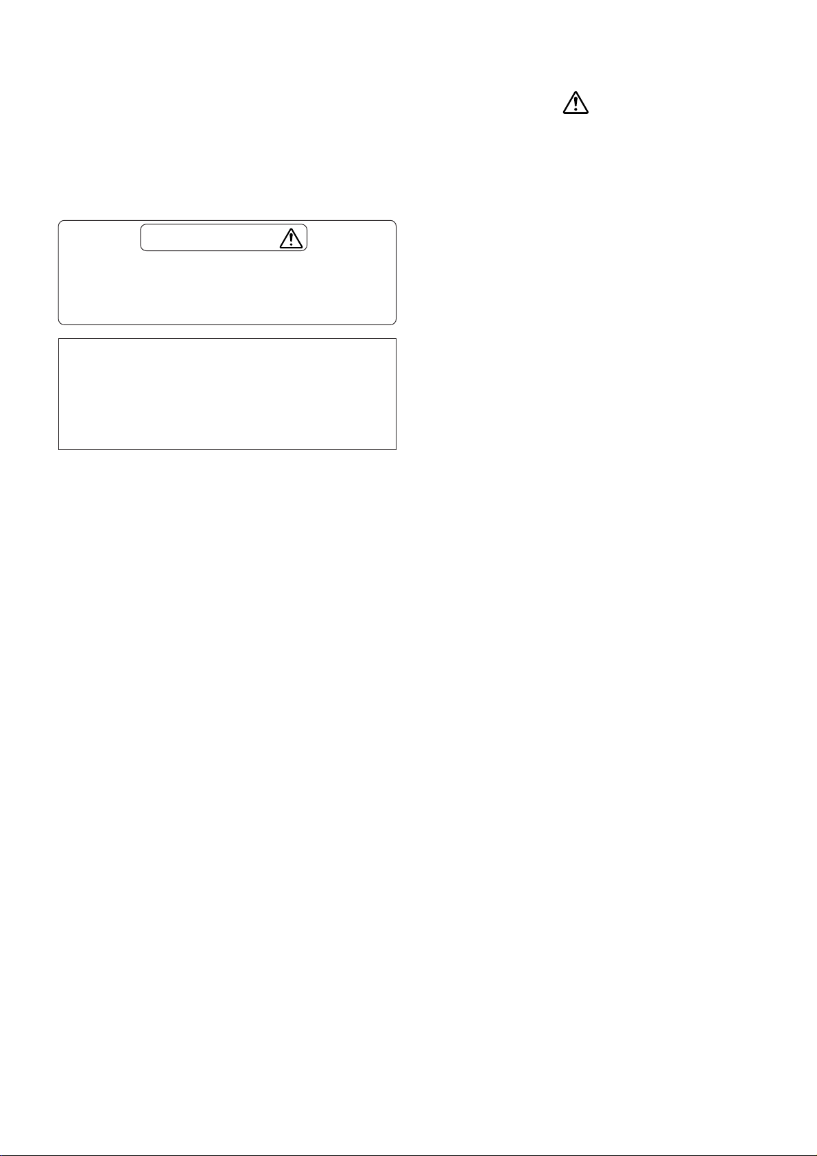
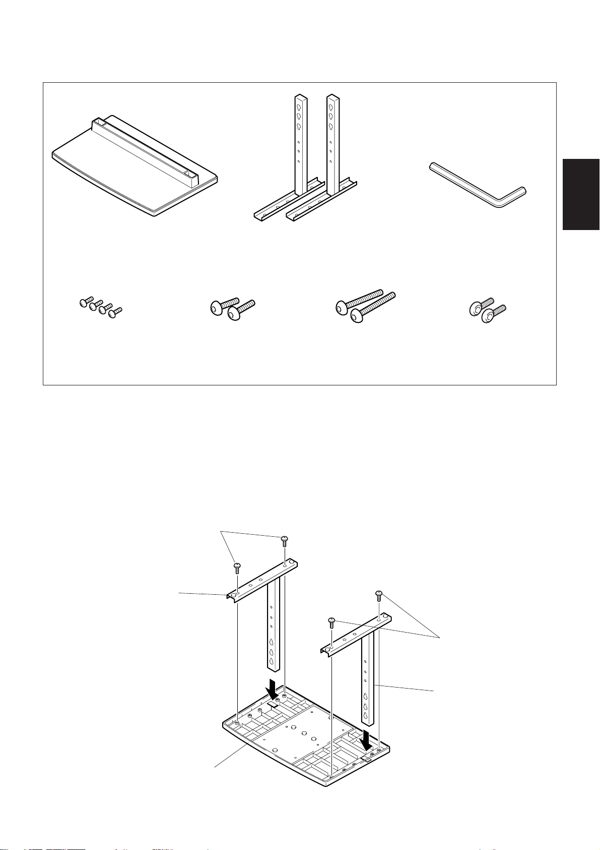
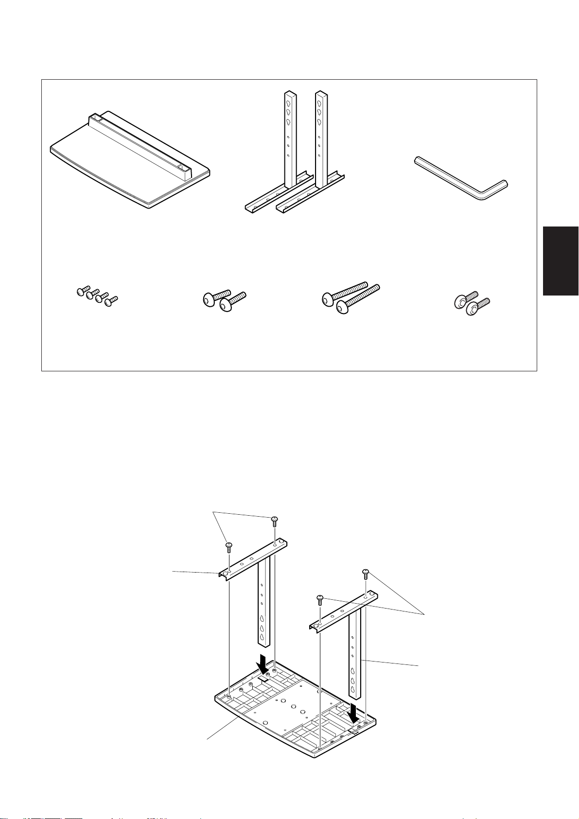
■構成部品の確認
日本語
•ベースカバー .............. 1 •スタンドパイプ(L,R共通)...... 2
•ネジ(4× 8)........4
•取り付けボルト1
(M8× 20) .................2
1.スタンドの組み立て
■組み立て手順
1. ベースカバーを裏側にする。
2. スタンドパイプをベースカバーに挿入する。
3. ネジでスタンドパイプをベースカバーに固定する。
ネジ(4×8)
•取り付けボルト2
(M8× 40) .................2
•六角レンチ..........1
•転倒防止用ボルト.... 2
スタンドパイプ
ネジ(4× 8)
スタンドパイプ
ベースカバー
3
Page 4
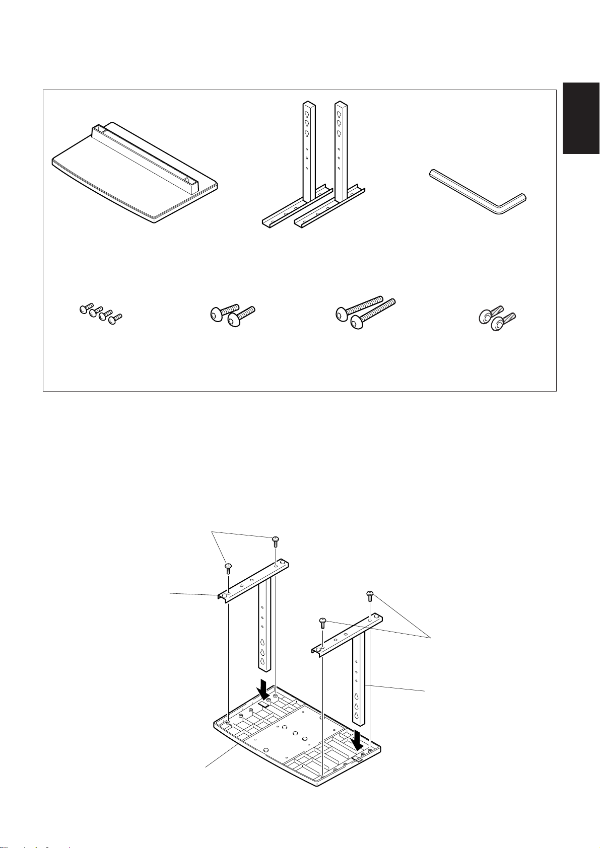
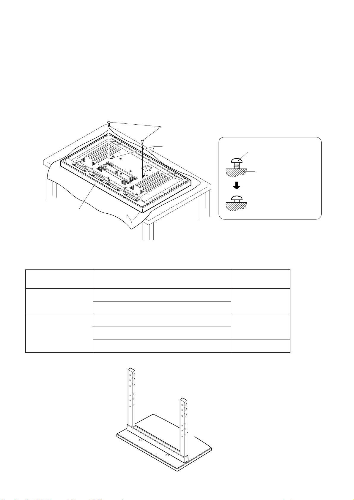
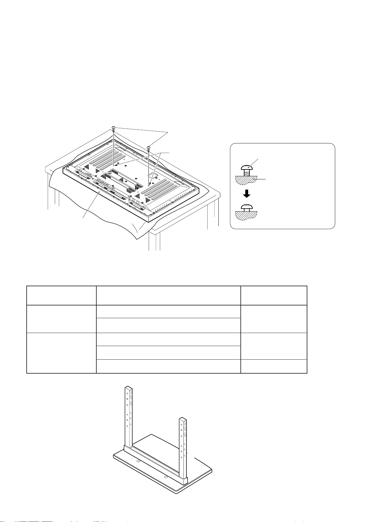
2.本体への取り付け
■通常の取り付け方法
手順1 プラズマディスプレイを寝かせた状態にして、取り付けボルト1(M8×20)2本を、プラ
ズマディスプレイ本体の穴aに取り付ける。
このとき、横から見て、取り付けボルト1 のネジ部が見えなくなったところで、ネジ止めを
やめてください。(最後までネジ止めすると、スタンドパイプの取り付けができなくなります。)
取り付けボルト1(M8 ×20)
穴a
(プラズマディスプレイ
中央部の穴)
プラズマディスプレイ本体
取り付けボルト1
プラズマ
ディスプレイ本体
ネジ部が見えなくなったと
ころでネジ止めをやめる。
◆テーブルトップスタンド側で使用するスタンドパイプのネジ穴について
表.テーブルトップスタンド側で使用するスタンドパイプのネジ穴
お客様のお買い上げ
プラズマディスプレイ
通常使用時
50型
43型
注:C,C'のネジ穴は、別売オプション対応等のネジ穴です。
本体両サイドにオプションスピーカー取り付け時
オプションスピーカー無し
本体両サイドにオプションスピーカー取り付け時
本体下側にオプションスピーカー取り付け時
仕 様
C
B
A
C´
B´
A´
C
B
A
C´
B´
A´
スタンド側で
使用するネジ穴
B,B'
A,A'
B,B'
4
Page 5
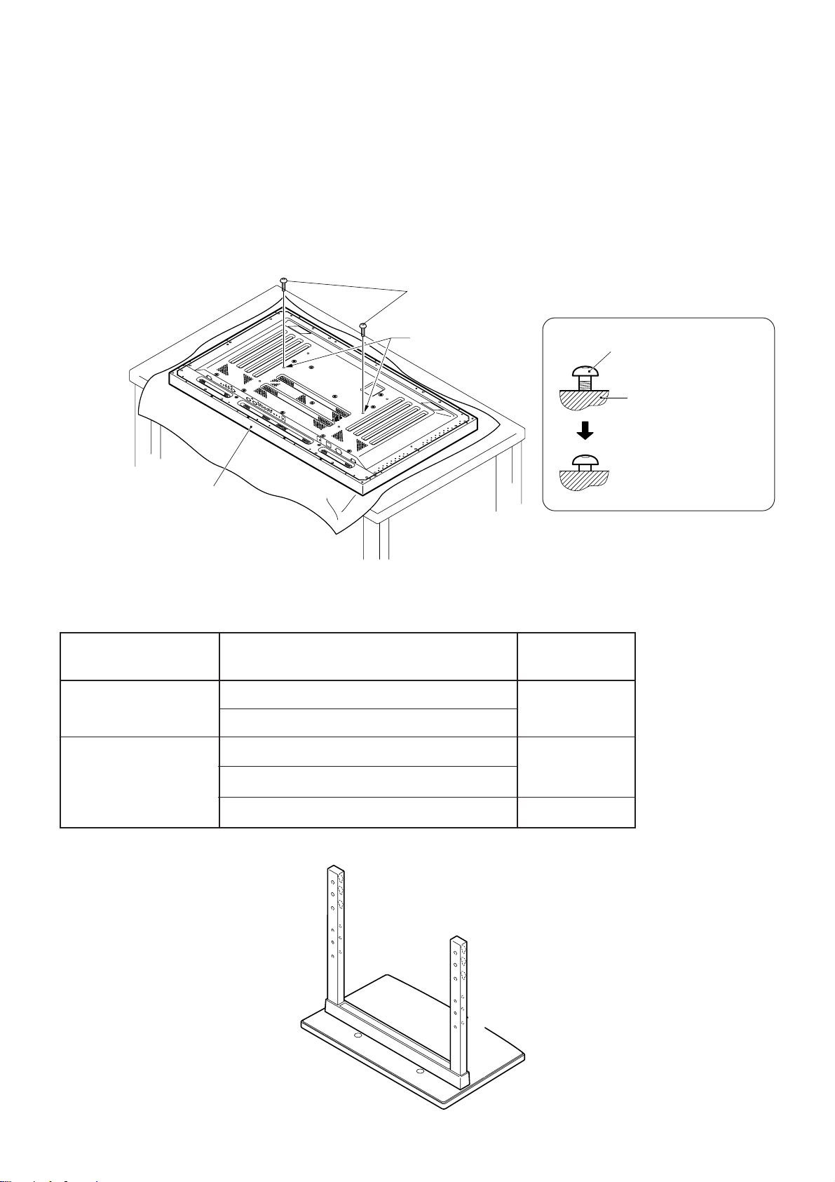
手順2 表に従い、取り付けボルト1 のネジ頭にスタンドパイプの穴(A,Bの何れか)を引っ掛けて、
スタンドをプラズマディスプレイ本体上方向にスライドさせ、取り付けボルト1 に突き当て
てください。(スライド量は、スタンドの構造上、19mm以下となります。)
手順3 付属の六角レンチを使用して、取り付けボルト2(M8×40)2本で、スタンドをプラズマ
ディスプレイ本体にネジ止めする。(使用する穴の組み合わせは、AーA'、BーB'の2通り
です。)
手順4 取り付けボルト1 を付属の六角レンチで締め付ける。
1. ディスプレイにキズ及び破損が生じないように、シートのようなものを敷いてください。
2. 必ず平坦なテーブルなどの上でプラズマディスプレイ本体を寝かせた状態で取り付けをしてください。
3. ボルトは穴に対して垂直に挿入し、必要以上に強く締め付けないでください。
ご注意
4. スタンドのネジ穴と本体の取り付けナット位置を必ず合わせてください。
5. ディスプレイは50型モデルでその質量が約40kgあり、奥行きがなく不安定なため、取り付け及び設置は必
ず2人以上で行ってください。
取り付けボルト2 (M8 ×40)(手順 3)
日本語
テーブルトップスタンド
スタンドをスライドさせる(手順2)
シート
5
Page 6
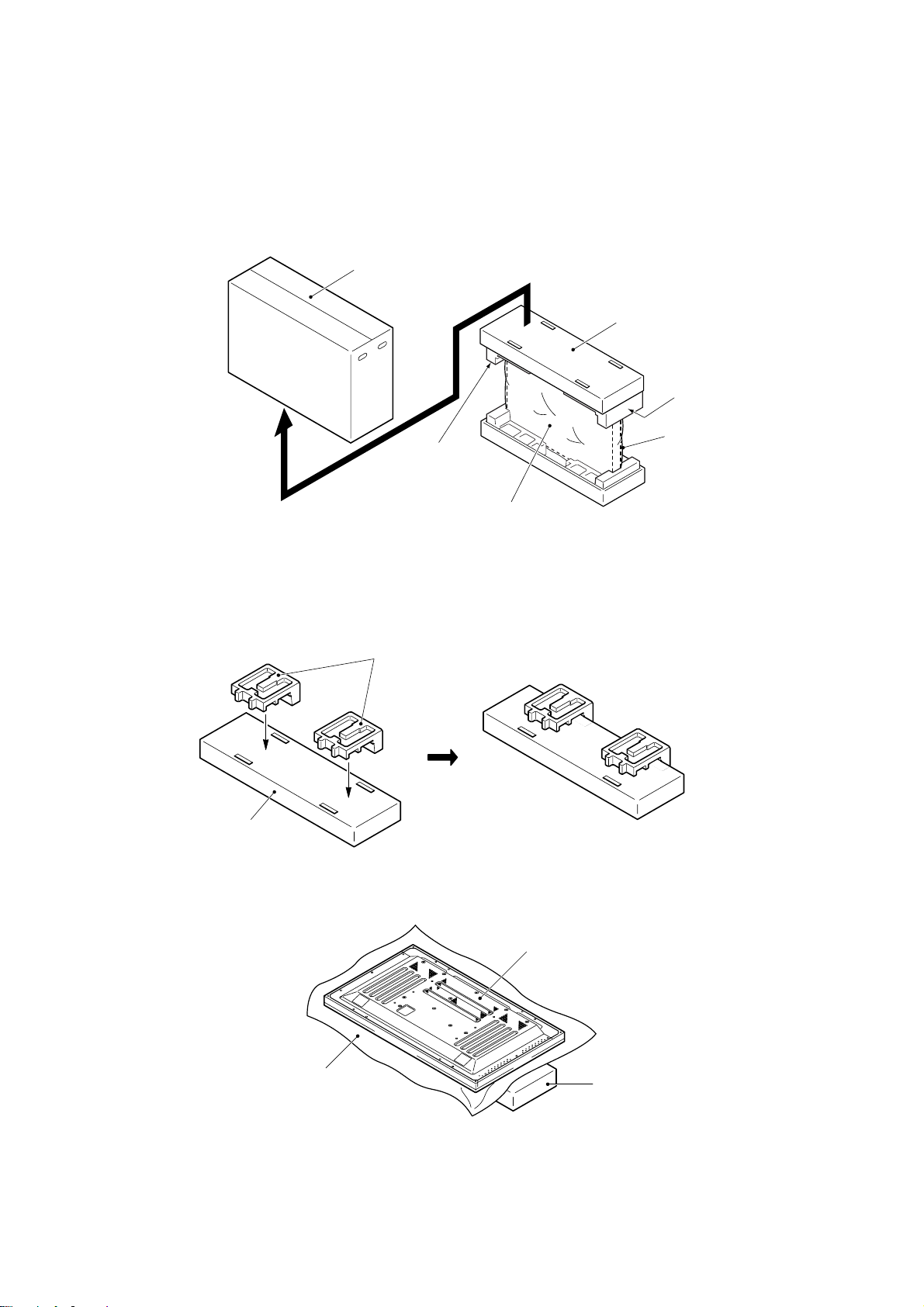
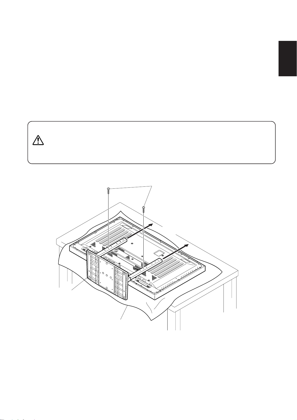
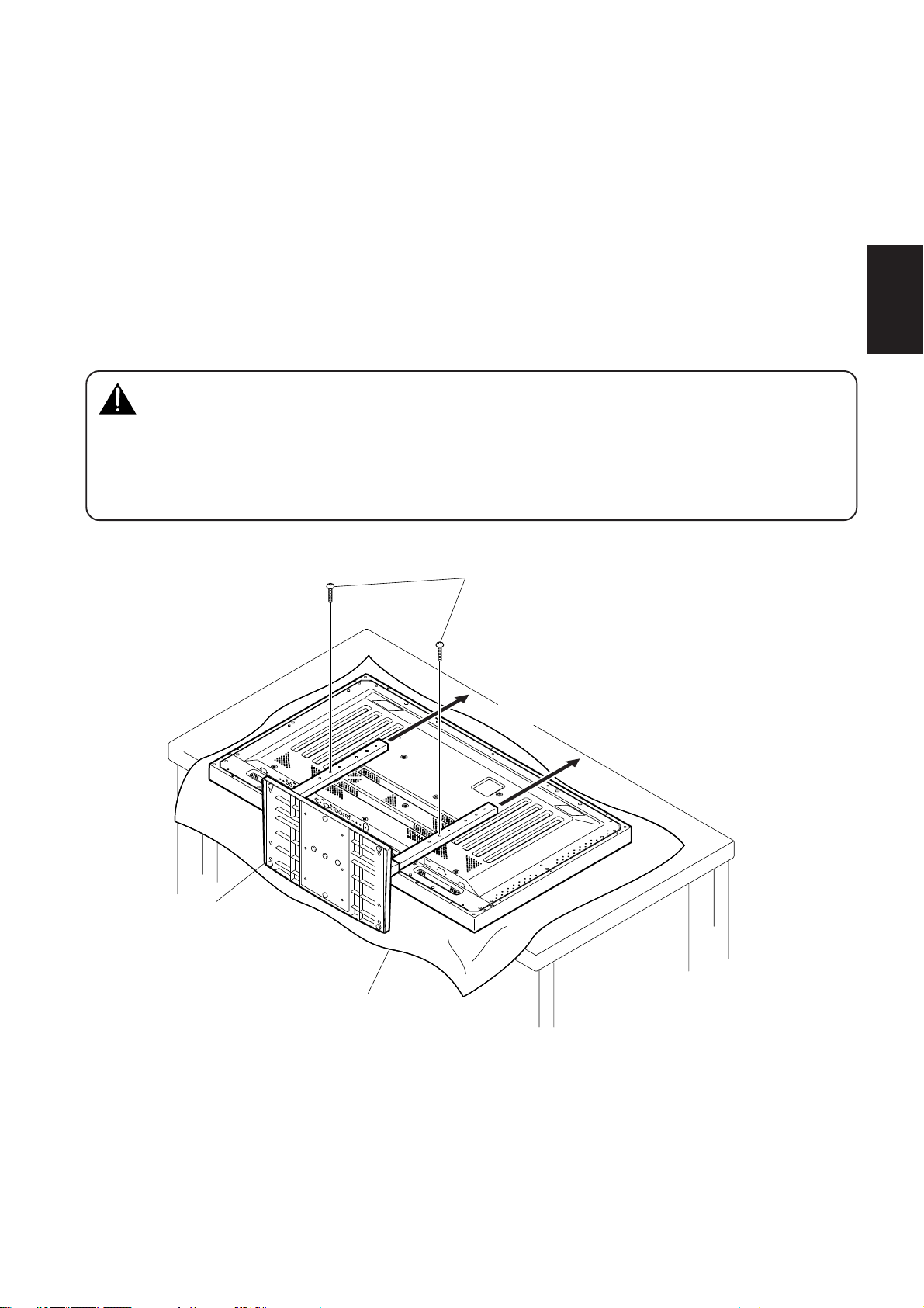
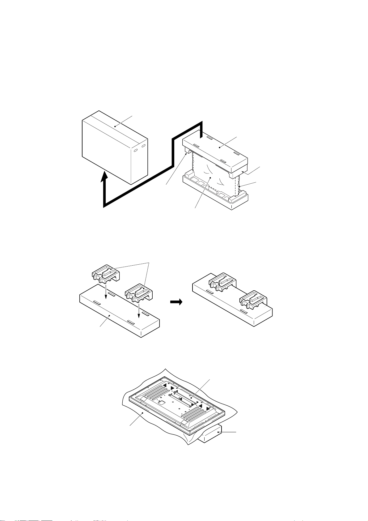
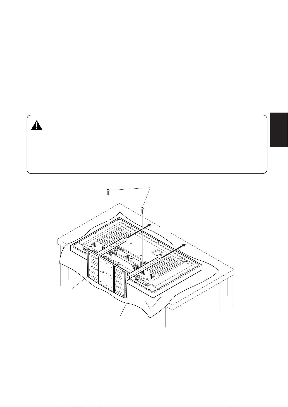
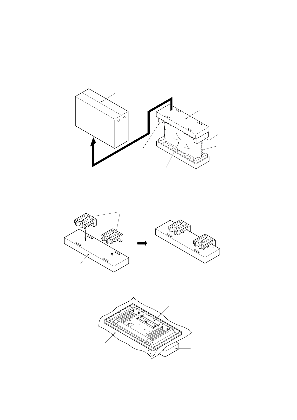
■ プラズマディスプレイ本体の梱包材を置台として使用する方法
(イラストは50型のものです)
◆プラズマディスプレイ本体の梱包箱の構成
外箱
中箱
パッド
パッド
プラズマディスプレイ本体
ミラーマット
手順1 上図に示した中箱とパッドを使い、プラズマディスプレイの置き台を作ります。(パッドは全
て同じです)
パッド
中箱
手順2 パッドの上にプラズマディスプレイ本体を下図のように置きます。
プラズマディスプレイ本体
ミラーマット
中箱の上にパッドを2つ置いた台
手順3 通常の取り付け方法の手順1〜手順4に従って、スタンドをプラズマディスプレイ本体に
取り付けます。
6
Page 7
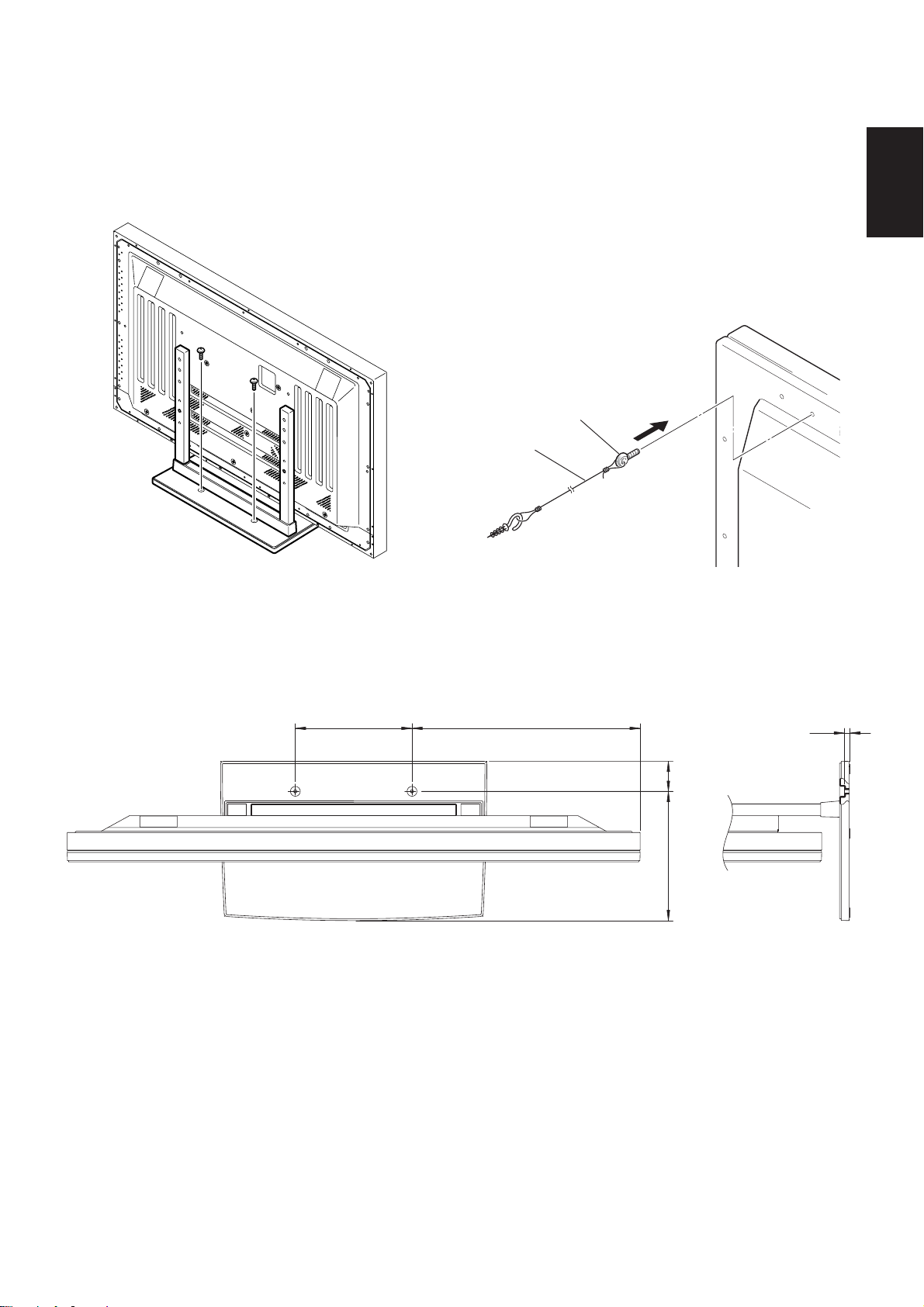
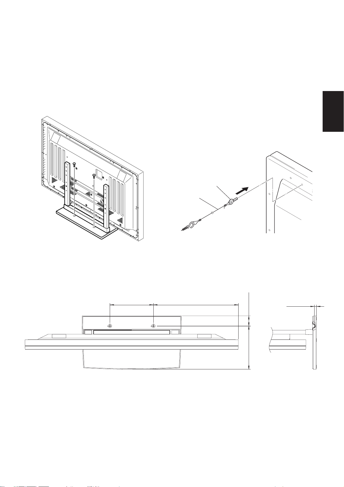
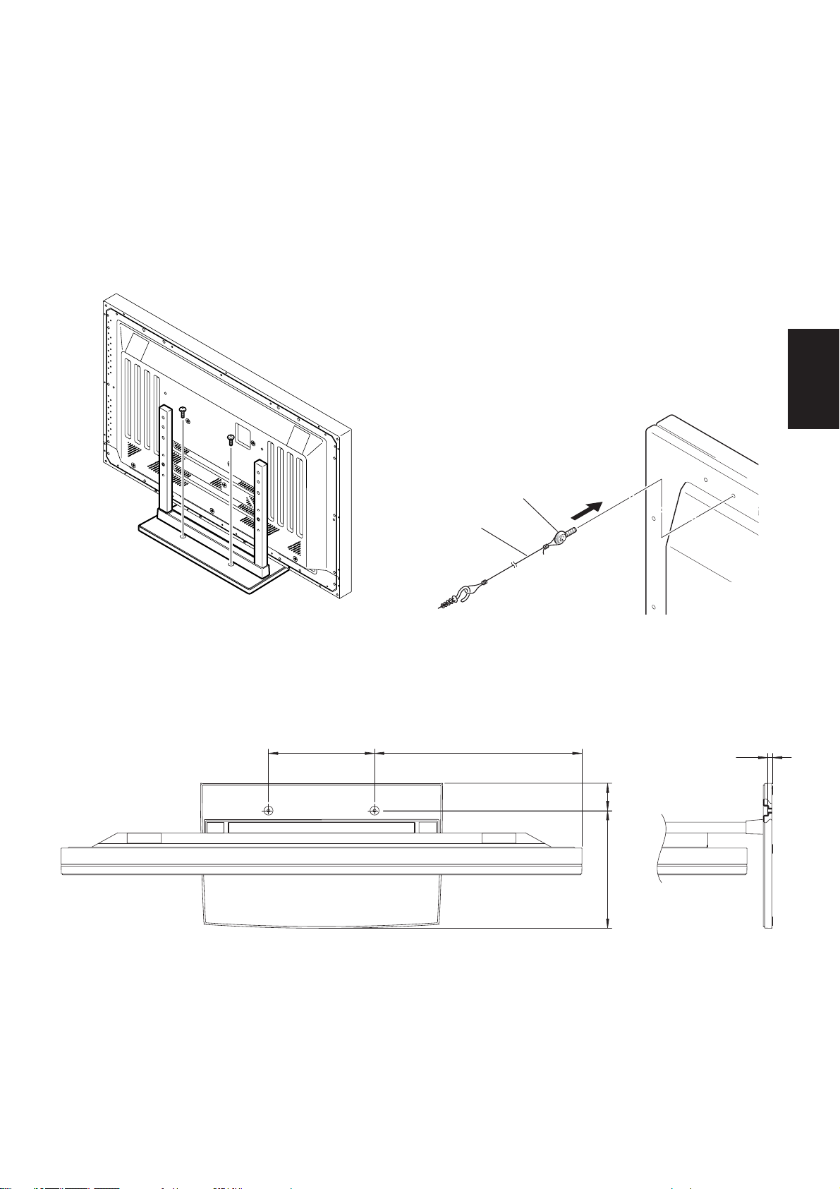
3.取り付け後、床に固定し転倒防止の備えをしてください
■床に固定する方法
●市販のネジを使って止める
■転倒防止用ボルトの使用例
(イラストは50型のものです)
1. プラズマディスプレイ本体に付属の転倒防止用ボルトを
つける。
2. 壁または柱に丈夫なヒモで固定する。
(左右対称に同様の作業を行ってください。)
ヒモ及びフックは市販のものをお使いください。
1
2
日本語
■床固定ネジ取付座標
※床に固定する際のネジは、M6、長さ20mm以上のものを使用してください。
単位:mm
485(50型)
248
411(43型)
■仕様
外形寸法...................................... 566(幅)x508(高)x339(奥行)mm
11.5
64
275
質量 ............................................4.0kg
............................................42.9kg(50型プラズマディスプレイ取り付け時)
35.5kg(43型プラズマディスプレイ取り付け時)
7
Page 8
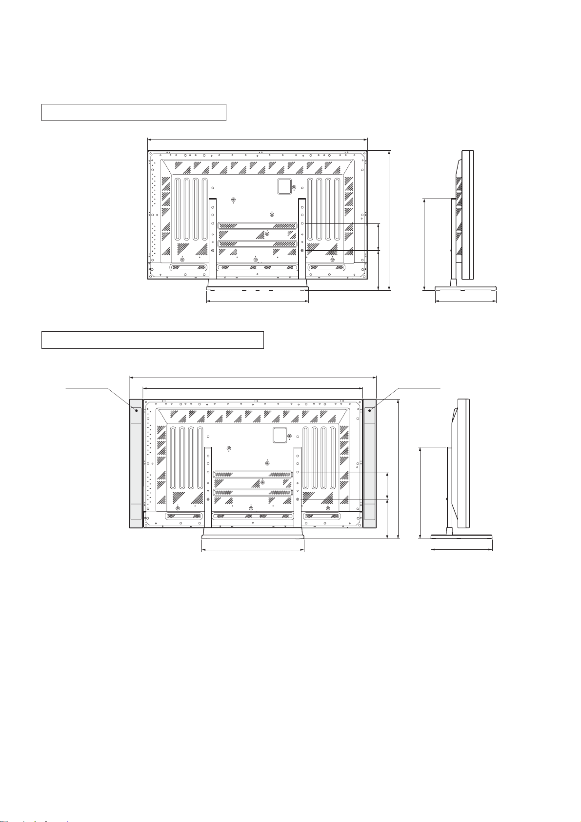
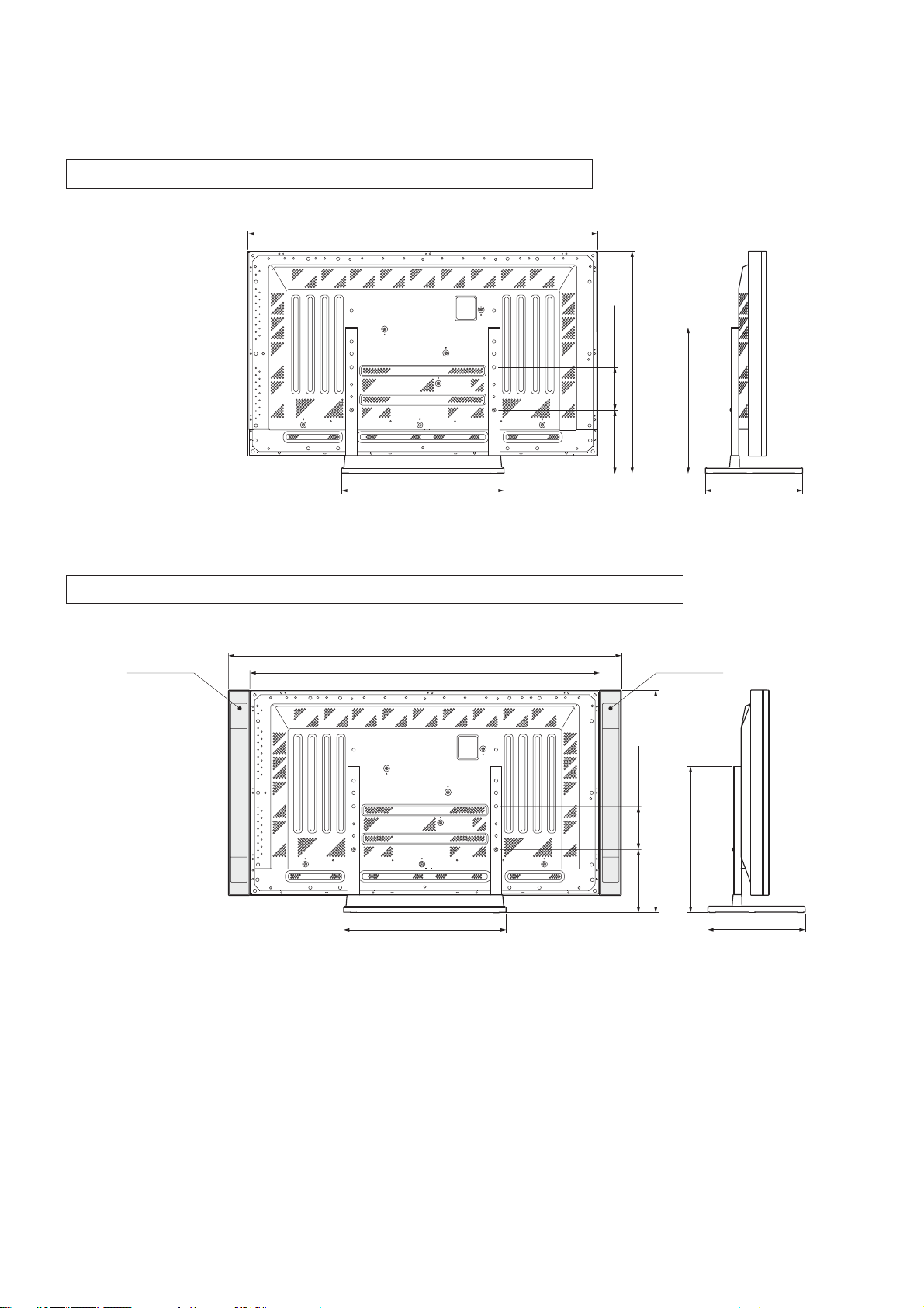
■寸法図
単位:mm
50型通常使用時(スピーカーなし)
1218
774
50型本体両サイドにスピーカー取り付け時
スピーカー
1368
1218
566
150220
774
150220
508
339
スピーカー
508
566
339
8
Page 9
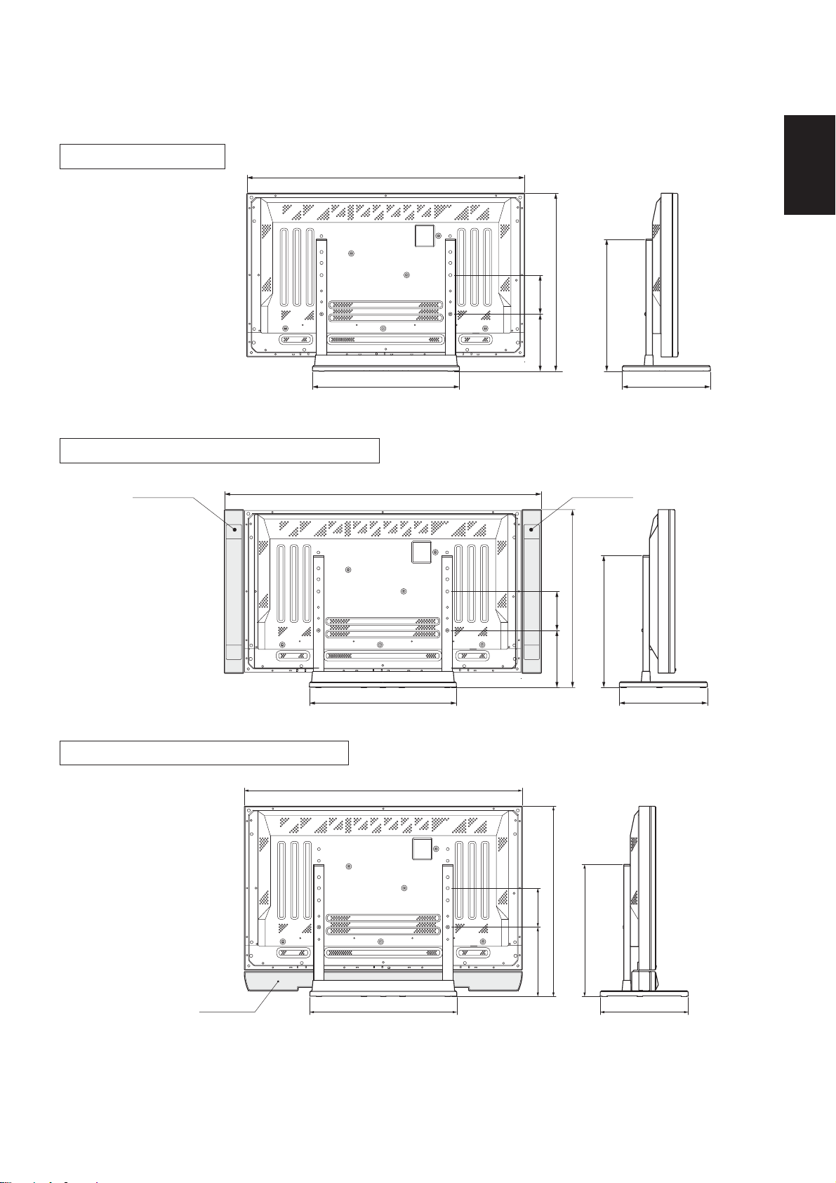
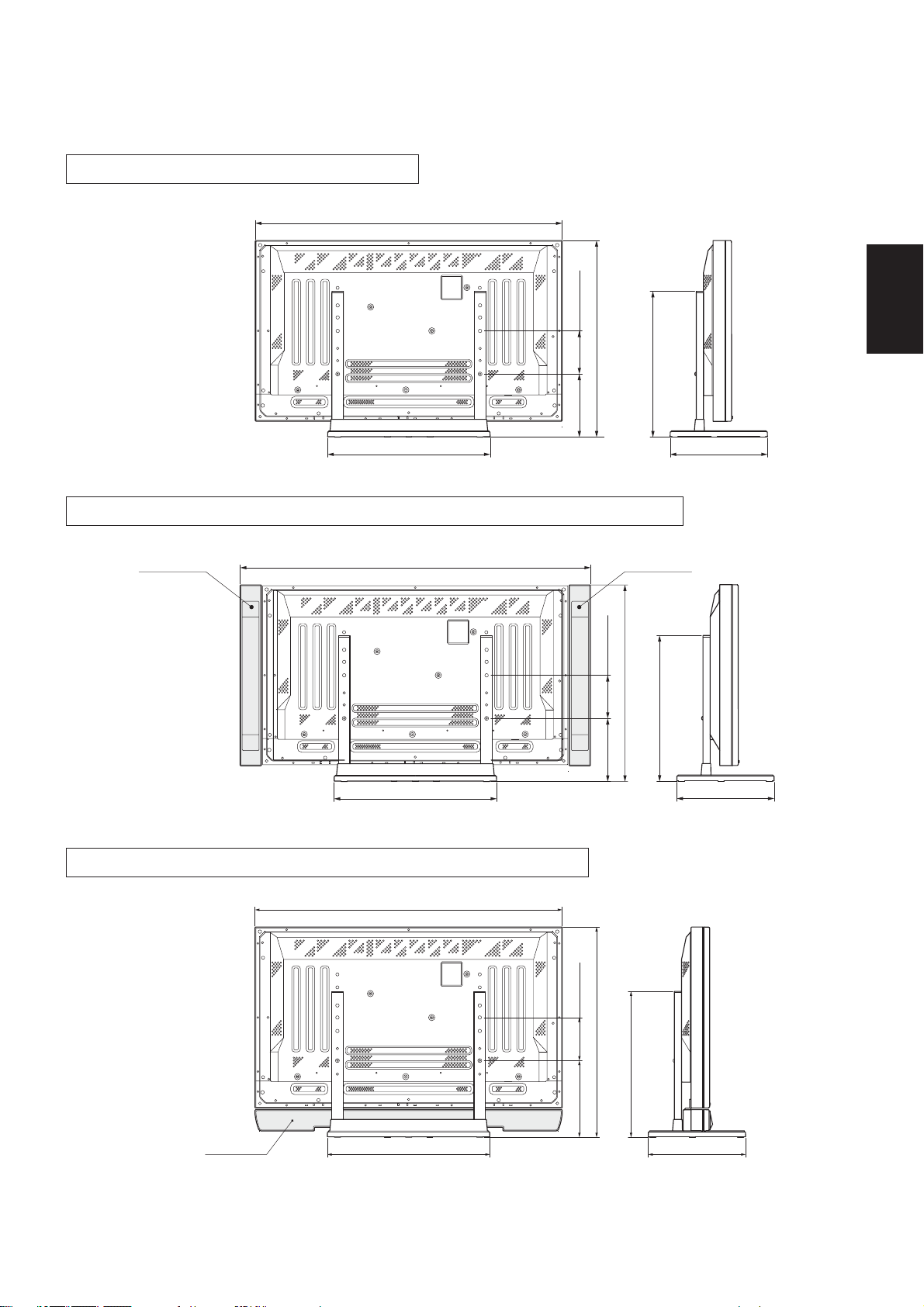
43型スピーカーなし
1070
日本語
685
508
220 150
43型本体両サイドにスピーカー取り付け時
スピーカー スピーカー
43型本体下側にスピーカー取り付け時
566
1220
566
1070
339
685
508
220 150
339
スピーカー
566
732
150
267
508
339
2001パイオニア株式会社 禁無断転載
9
Page 10
Thank you for buying this Pioneer product.
Please read through these operating instructions so you will
know how to operate your model properly. After you have finished reading the instructions, put them away in a safe place
for future reference.
CAUTION
This symbol refers to a hazard or unsafe practice which
can result in personal injury or property damage.
Installation
¶ Consult your dealer if you encounter any difficulties with
this installation.
¶ Pioneer is not liable for any damage resulting from im-
proper installation, improper use, modification, or natural
disasters.
Cautions
1. This table top stand was exclusively designed for plasma
displays produced by PIONEER.
2. Do not use this stand for a plasma display or any other
purpose that is not specified. The stand should not be
modified and should only be used for plasma displays.
3. Improper installation may result in the stand falling over
and cause serious injury. Be sure to have the plasma display lying flat when attaching the stand to the main display.
4. Installation Location
(a) Make sure to install the stand in a location that can
sufficiently support the combined weight of the
stand and the display.
(b) The installation location should be a completely flat
and stable surface. Take proper precautions when
installing the stand to make sure that the weight of
the display is equally distributed throughout the
stand.
(c) Do not install this stand outdoors, at a hot spring, or
near a beach.
(d) Do not install this stand where it may be subjected
to vibration or shock.
5. (a) Assemble the stand in accordance with all of the
instructions and securely stabilize the stand with
screws at all locations that are indicated.
There have been cases where after installing the
display, damage has occurred from the stand falling over or similar situations.
(b) To assure that the display is installed safely, installa-
tion should be performed with more than two
people.
(c) Before installation, turn off the power for the dis-
play and peripheral devices, then remove the power
cord plug from the power outlet.
10
Page 11
7 Check That You Have All the Parts
English
• Base cover .................. 1 • Stand pipes
(left and right, interchangable) .... 2
• Screws (4 x 8) ........... 4
• Installation bolts 1
(M8 x 20) ...................... 2
1. Stand assembling
7 Assembling Steps
1. Turn the base cover over so the underside is facing up.
2. Insert the stand pipes into the base cover.
3. Use the included screws to stabilize the stand pipes.
Screws (4 x 8)
• Installation bolts 2
(M8 x 40) ........................ 2
• Hexagonal wrench
................................ 1
• Stabilization bolts
................................ 2
Stand pipe
Screws (4 x 8)
Stand pipe
Base cover
11
Page 12
2. Stand attaching to the Plasma Display
7 Normal Installation
Step 1. With the plasma display lying flat, insert and secure the two Installation bolts 1 (M8 x 20)
in the holes "a" located in the plasma display housing.
At this point, tighten these bolts 1 only until the threads are no longer visible when
viewed from t he side (you will be unable to attach the display if the bolts are screwed in
completely).
Installation bolt 1 (M8 x 20)
Holes "a"
(holes in center of
plasma display)
Plasma display
Installation bolt 1
Plasma display housing
Stop screwing down the
bolt when the threads are
no longer visible.
Regarding the stand pipe screw holes when the stand is used as a desktop stand
Table: Stand pipe screw holes when the stand is used as a desktop stand
Plasma display model
Normal use
50"
With optional speakers attached to both sides of display
Without optional speakers
43"
Note: Holes C and C' are for attaching options available separately, etc.
With optional speakers attached to both sides of display
With optional speakers attached at bottom of display
C
B
A
C
´
B´
A´
Specifications
C
B
A
C
B´
A´
´
Screw holes used with
stand orientation
B,B'
A,A'
B,B'
12
Page 13
Step 2. As shown in figure, hook the stand pipe holes (either pipe A or B) onto the screw heads
of the installation bolts 1, then slide the stand upwards to the main plasma display until
it engages the installation bolts 1 (once put together with the display, the stand will
slides no more than 19 mm (3/4 inch)).
Step 3. Pass the installation bolts 2 (M8 x 40) through the stand pipes and tighten the installa-
tion bolts securely with the included hexagonal wrench (The holes shpuld be used in the
proper combinations, A–A' and B–B').
Step 4. Tighten the installation bolts 1 securely with the hexagonal wrench provided.
1. Place a sheet or protective cover to protect the display from scratches or damage.
2. Assemble only with the plasma display lying flat on a table or similar surface.
Notes
3. Insert the bolts vertically in the holes and tighten them, but do not apply excessive pressure that tightens them
more than necessary.
4. Move the stand so that the stand screw holes and the nuts that connect the main display line up correctly.
5. The display is a 50” model that weighs approximately 40 kilograms (88 lb) and has little depth, making the
display very unstable. For this reason, at least two people are required for setup and installation.
Installation bolts 2 (M8 x 40) (Step 3)
Slide the stand (Step 2)
English
Table top stand
Sheet
13
Page 14
7 Instructions for using the main display packing material as a stand for
the working on the display (50” display model is shown in the figure.)
• Main plasma display packaging setup
Outer box
Inner box frame
Pad
Pad
Plasma display
Mirror mat
Step 1. Construct the stand for the plasma display using the inner box frame and pads shown in
the figure above (all pads are identical).
Pads
Inner box frame
Step 2. Set the plasma display down on the pads as shown in the figure below.
Plasma display
Mirror mat
Inner box frame topped by two pads
Step 3. Follow the instructions in Steps 1-4 in "Normal Installation" to attach the stand to the
plasma display.
14
Page 15
3. After assembling, connect the stand to the
floor to prevent from falling over.
7 Stabilizing to the floor
¶ Use screws (sold separately) to attach and stabilize the
stand.
7 Sample use of the stabilization bolts
(50” display model is shown in the figure.)
1. Attach the stabilization bolts that come with the plasma
display.
2. Stabilize the display by connecting to a wall or standing
beam with a strong cord.
(Repeat the same steps in the laterally direction to stabilize the assembly to the left and right.)
Use cord and hooks that are available on the market (sold separately).
1
2
English
7 Installation coordinates for screws used to stabilize the stand to
the floor
* When stabilizing the stand to the floor, use M6 with a length above 20 mm (25/32 inch).
Units: mm (inch)
485 (19-3/32) [50” display]
248 (9-3/4)
411 (16-3/16) [43” display]
11.5 (29/64)
64 (2-17/32)
275 (10-13/16)
7 Specifications
Dimensions .............................. 566 (W) x 508 (H) x 339 (D) mm
(22-9/32 (W) x 20 (H) x 13-11/32 (D) in.)
Weight...................................... 4.0 kg (8.82 lb)
..................................... 42.9 kg (94.58 lb) (When the 50” plasma display is attached)
35.5 kg (78.27 lb) (When the 43” plasma display is attached)
15
Page 16
7 Dimensions Diagram
Units: mm (inch)
50" display under normal use (without optional speakers)
1218 (47-15/16)
566 (22-9/32)
150 (5-29/32)
774 (30-15/32)
508 (20)
220 (8-21/32)
339 (13-11/32)
50" display with optional speakers attached to both sides of display
1368 (53-27/32)
Speaker
1218 (47-15/16)
150 (5-29/32)
774 (30-15/32)
220 (8-21/32)
566 (22-9/32)
Speaker
508 (20)
339 (13-11/32)
16
Page 17
43" display without optional speakers
1070 (42-1/8)
150 (5-29/32)
685 (26-31/32)
220 (8-21/32)
566 (22-9/32)
508 (20)
43" display with optional speakers attached to both sides of display
Speaker Speaker
1220 (48-1/32)
150 (5-29/32)
(26-31/32)
685
508 (20)
English
339 (13-11/32)
566 (22-9/32)
43" with optional speakers attached at bottom of display
1070 (48-1/32)
Speaker
566 (22-9/32)
220 (8-21/32)
150 (5-29/32)
732
267 (10-1/2)
508 (20)
339 (13-11/32)
339 (13-11/32)
Published by Pioneer Corporation.
Copyright © 2001 Pioneer Corporation.
All rights reserved.
17
Page 18
Merci d’avoir choisi ce produit pioneer.
Nous vous invitons à lire les informations utiles à l’utilisation
et à l’installation de ce produit. Apres avoir lu attentivement
ces instructions, ranger les soigneusement afin de vous en
servir pour de futures références.
Attention
Ce signe symbolise un risque ou un danger qui peut
provoquer des blessures ou des dégâts matériels.
Installation
¶ Consultez votre distributeur si vous rencontrez quelque
difficulté avec cette installation.
¶ Pioneer décline toute responsabilité en cas de mauvaise
installation et utilisation, de modification ou de catastrophes naturelles.
Attention
1. Ce support de dessus de table est exclusivement conçu
pour l’affichage de plasma fabriqué par pioneer.
2. N’utilisez ce support pour aucun affichage de plasma ou
dans un but non indiqué. Ce support ne devrait pas être
modifié, mais seulement utilisé pour des affichages de
plasma.
3. Une mauvaise installation provoquerait la chute du support, causant de sérieuses blessures. Assurez-vous que
l’affichage de plasma se trouve à plat pendant que vous
le reliez à l’affichage principal.
4. Emplacement de l’installation
(a) Assurez-vous d’installer le support dans un endroit
qui peut largement supporter le poids combiné du
support et de l’affichage.
(b) Cet emplacement devrait-être une surface
complètement plate et stable.
Prenez les précautions nécessaires en installant le
support pour s’assure que le poids de l’affichage
est également réparti dans tout le support.
(c) N’installez pas ce support dehors, près d’un cou-
rant chaud ou d’une plage.
(d) Installez ce support dans un endroit à l’abri des vi-
brations ou des chocs.
5. (a) Assemblez le support suivant toutes les instructions
et le stabiliser solidement avec des vis à tous les
emplacements indiqués.
Après l’installation de l’affichage, la chute du support a causé des dégâts dans certains cas ou dans
des situations similaires.
(b) Pour s’assurer de la bonne installation de l’affichage,
elle devrait être faite par plus de deux personnes.
(c) Avant l’installation, coupez le courant pour l’affichage
et les périphériques, puis retirez la prise de cordon
de secteur de la prise de courant.
18
Page 19
7 Vérifiez que vous avez toutes les pièces
• Couverture de base .... 1 • Piliers du support
(gauche et droite semblables) ..... 2
• Vis (4 x 8) ................... 4
• Boulons d’installation 1
(M8 x 20) ...................... 2
• Boulons d’installation 2
(M8 x 40) ........................ 2
1. Assemblement du support
7 Etapes d’assemblement
1. Tournez la couverture de base afin que le côté en dessous fasse face vers le haut.
2. Insérez les piliers du support dans la couverture de base.
3. Utilisez les vis incluses pour stabiliser les piliers du support.
Vis (4 x 8)
• Clé hexagonale
................................ 1
Françias
• Boulons de stabilisation
................................ 2
Pilier du support
Couverture de base
Vis (4 x 8)
Pilier du support
19
Page 20
2. Support de l’affichage de plasma
7 Installation normale
Etape 1. Avec l’affichage de plasma se trouvant à plat, insérez et fixez les 2 boulons d’installation
1 (M8x20) dans les trous "a" situés dans le logis de l’affichage de plasma.
A ce point, serrez ces boulons 1 seulement jusqu’à ce que les amorçages ne soient plus
visibles, vu du côté (Vous ne pourrez pas attacher l’affichage si les boulons sont
complètement vissés).
Boulon d’installation 1 (M8 x 20)
Trous "a" (trous au centre
de l’écran plasma)
Affichage de plasma
Boulon d’installation 1
Logis de l’affichage de
plasma
Arrêtez de visser le boulon
quand ces amorçages ne
sont plus visibles.
Vision des trous de vis du pilier du support quand ce dernier est utilisé comme support de
surface de table.
Table: Les trous de vis du pilier de support quand ce dernier est utilisé comme support de surface de table
Modèle d’écran plasma
50 pouces
Spécificités
Utilisation normale
Avec haut-parleurs optionnels fixés aux deux côtés de l’écran
Trous de vis utilisés avec
orientation de support
B,B'
Sans haut-parleurs optionnels
43 pouces
Remarque: Les trous C et C' sont destinés á des options d’attachement disponibles séparément etc.
Avec haut-parleurs optionnels fixés aux deux côtés de l’écran
Avec haut-parleurs optionnels fixés au bas de l’écran
C
B
A
C´
B´
A´
C
B
A
C´
B´
A´
A,A'
B,B'
20
Page 21
Etape 2. Comme représenté sur la figure, accrochez les trous de piliers du support (tube A ou
bien B) sur les têtes de vis des boulons d’installation 1. Puis glissez le support vers le
haut à l’affichage de plasma principal jusqu’à ce qu’il engeance les boulons d’installation
1 (une fois assemblé avec l’affichage, le support ne glissera pas plus de 19 mm).
Etape 3. Passez les boulons d’installation 2 (M8x40) par les piliers du support et serrez-les
proprement avec la clé hexagonale (Les orifices doivent être utilisés selon la combinaison
correcte : A–A' et B–B').
Etape 4. Serrez les boulons d’installation 1 avec la clé hexagonale fournie.
1. Mettez une feuille ou une couverture de protection pour protéger l’affichage des égratignures et des dégâts.
2. Réunissez les différents pièces seulement avec l’affichage de plasma se trouvant à plat sur une table ou une
Notes
surface similaire.
3. Insérez verticalement les boulons dans les trous et serrez-les, sans toutefois appliquer une pression excessive, qui les serrerait plus fort que nécessaire.
4. Déplacez le support de sorte que ses trous de vis et les écrous qui relient l’affichage principale s’alignent
correctement.
5. L’écran est un modèle de 50 pouces, qui pèse environ 40 kilogrammes et a peu de profondeur, ce qui le rend
très instable. Pour cette raison, il y a besoin d’au moins deux personnes pour le montage et l’installation.
Boulons d’installation 2 (M8 x 40) (Etape 3)
Françias
Support de couverture de table
Glisser le support (Etape 2)
Feuille
21
Page 22
7 Instructions pour l’usage du matériel d’emballage de l’affichage
principal comme un support pour le travail sur l’affichage
(L’écran de 50 pouces est présenté sur la figure)
• Empaquetage de l’affichage principal de plasma
Boîte externe
Cadre de boîte intérieure
Garniture
Garniture
Affichage de plasma
Natte de miroir
Etape 1. Construisez le support pour à l’aide du cadre de boîte intérieure et des garnitures
représentées sur la figure ci-dessus (toutes les garnitures sont identiques).
Garnitures
Cadre de boîte intérieure
Etape 2. Placez l’affichage de plasma vers le bas sur les garnitures comme représenté sur la fig-
ure ci-dessous.
Affichage de plasma
Natte de miroir
Cadre de boîte intérieure surmonté par 2
garnitures.
Etape 3. Suivez les instructions dans les étapes 1-4 dans "installation normale" pour rattacher le
support à l’affichage de plasma.
22
Page 23
3. Après le rassemblement des différentes
parties, reliez le support au sol afin d’éviter sa
chute.
7 Fixation au sol
¶ Utilisez des vis (vendues séparément) pour rattacher et fixer
le support.
7 Modèle d’utilisation des boulons
de fixatio (le modèle de 50 pouces
est représenté sur la figure)
1. Attachez les boulons de fixation fournis avec l’écran
plasma.
2. Fixez l’affichage en le reliant à un mur ou un faisceau vertical à l’aide d’une corde solide.
(Répétez les mêmes étapes latéralement pour fixer
l’assemblage à gauche et à droite)
Utilisez la corde et les crochets qui sont disponibles sur le
marché (vendus séparément)
1
2
Françias
7 Coordination de l’installation des vis utilisées pour fixer le support
au sol
*Pendant que vous fixez le support au mur, utilisez M6 avec une longueur au-dessus de 20 mm.
Unités: mm
485 (écran de 50 pouces)
248
411 (écran de 43 pouces)
11.5
64
275
7 Spécificités
Dimensions .............................. 566 (W) x 508 (H) x 339 (D) mm
Poids ........................................ 4,0 kg
..................................... 42,9 kg (si l’écran plasma de 50 pouces est fixé)
35,5 kg (si l’écran plasma de 43 pouces est fixé)
23
Page 24

7 Dimensions du schéma
Unités: mm
L’écran de 50 pouces sous utilisation normale (sans haut-parleurs optionnels)
1218
774
150220
566
508
339
L’écran de 50 pouces avec haut-parleurs optionnels fixés aux deux côtés de l’écran
Haut-parleur
1368
1218
Haut-parleur
774
150220
508
24
566
339
Page 25

L’écran de 43 pouces sans haut-parleurs optionnels
1070
685
508
220 150
566
339
L’écran de 43 pouces avec haut-parleurs optionnels fixés aux deux côtés de l’écran
Haut-parleur
1220
566
Haut-parleur
685
508
220 150
339
L’écran de 43 pouces avec haut-parleurs optionnels fixés au bas de l’écran
Françias
Haut-parleur
1070
566
732
150
267
508
339
Publication de Pioneer Corporation.
© 2001 Pioneer Corporation.
Tous droits de reproduction et de traduction réservés.
25
Page 26

Wir bedanken uns bei Ihnen für den Kauf dieses Pioneer
Produktes.
Bitte lesen Sie diese Bedienungsanleitung aufmerksam durch
um Ihr Produkt entsprechend benutzen zu können. Nachdem
Sie die Bedienungsanleitung gelesen haben, legen Sie sie
beiseite.
Vorsicht
Dieses Symbol weist auf Gefahr oder unsicheren
Gebrauch hin, was zu Verletzungen und Schaden führen
kann.
Installation
¶ Bei Schwierigkeiten bei der Installation wenden Sie sich
bitte an Ihrem Händler.
¶ Pioneer trägt keine Verantwortung für die Schaden die
durch unvorschriftsmäßige Installation, Benutzung und
Modifikation oder durch Naturkatastrophen angerichtet
wurden.
Vorsicht
1. Dieses Tischgestell wurde ausschließlich für dieses
Plasma Display von Pioneer entworfen.
2. Wenden Sie das Tischgestell nicht zu anderem Plasma
Display, oder zu anderem Zweck an, der nicht spezifiziert
ist. Das Tischgestell darf nicht modifiziert werden, und
darf nur zu Plasma Displays benutzt werden.
3. Zufolge einer unvorschriftsmäßigen Installation könnte
das Gestell umstürzen und schwere Verletzungen
anrichten. Vergewissern Sie sich, daß das Plasma Display waagrecht liegt, während Sie das Gestell an das
Plasma Display anschließen.
4. Installationsort
(a) Vergewissern Sie sich, daß Sie zur Aufstellung eine
Fläche finden, die das gesamte Gewicht des
Gestells und Plasma Displays halten kann.
(b) Die Fläche zur Aufstellung sollte waagrecht und
stabil sein. Seien Sie bei der Aufstellung vorsichtig
genug, daß sich das Gewicht des Displays am
Gestell gleichmäßig verteilt.
(c) Vermeiden Sie es unbedingt das Display an einem
Ort aufzustellen, wo das Gerät direktem
Sonnenlicht, hoher Luftfeuchtigkeit ausgesetzt wird.
(d) Vermeiden Sie es unbedingt das Display an einem
Ort aufzustellen, wo das Gerät Vibrationen oder
möglichem Stoß ausgesetzt wird.
5. (a) Aller Instruktionen nach stellen Sie das Gestell
zusammen, und stabilisieren Sie es mit den
Schrauben an jeder angegebenen Stelle. Es kam vor,
daß wegen Umstürzung des Gestells oder ähnlichen
Situationen nach der Aufstellung Schaden
enstanden.
(b) Bei der Aufstellung braucht man mehr als zwei
Menschen damit die Installation einwandfrei
auszuführen ist.
(c) Vor der Installation schalten Sie das Gerät aus, und
trennen Sie es von der Wandsteckdose ab.
26
Page 27

7 Kontrollieren Sie, daß Sie über alle Komponenten verfügen
• Unterlage .................... 1 • Gestellröhre
(links und rechts, umsetzbar) ....... 2
• Schrauben (4 x 8) ...... 4 • Senkkopfschrauben zur
Installation 1
(M8 x 20) ...................... 2
• Senkkopfschrauben zur
Installation 2
(M8 x 40) ........................ 2
1. Der Zusammenbau des Gestells
7 Schritte des Zusammenbaus
1. Drehen Sie die Unterlage aufwärts.
2. Stecken Sie die Gestellröhre in die Unterlage.
3. Befestigen Sie die Gestellröhre mit den mitgelieferten Schrauben.
Schrauben (4 x 8)
• Hexangulärer Schraubenzieher
................................ 1
• Senkkopfschrauben zur
Stabilization .............. 2
Deutsch
Gestellrohr
Schrauben (4 x 8)
Gestellrohr
Unterlage
27
Page 28

2. Anschluß des Gestells an das Plasma Display
7 Normal Installation
Schritt 1. Wenn das Plasma Display waagrecht liegt, sollen Sie die zwei Senkkopfschrauben zur
Installation 1 (M8 x 20) in den Klemmen "a" befindlich an dem Gehäuse des Plasma
Displays anschließen und befestigen.
Da sollen Sie die Schrauben solange ziehen bis der Gang von der Seite nicht zu sehen ist
(Sie können das Display nicht anschließen wenn die Senkkopfschrauben völlig eingedreht
sind).
Senkkopfschrauben zur Installation 1 (M8 x 20)
Klemmen "a" (Schraublöcher
in der Mitte des
Plasmabildschirms)
Plasma Display
Senkkopfschrauben zur Installation 1
Gehäuse des Plasma
Displays
Hören Sie auf die
Schrauben einzudrehen,
wenn der Gang nicht mehr
zu sehen ist.
Informationen über die Löcher der Gestellröhre wenn das Gestell als Tischgestell benutzt wird
Tabelle: Schraublöcher in den Vierkantrohren des Ständers bei Verwendung als Tischständer
Plasmabildschirm-Modell
Normaler Gebrauch
50"
43"
Hinweis: Die Schraublöcher C und C' dienen der Befestigung der auf Wunsch gesondert erhältlichen Bauteile.
Mit wahlweise mitgelieferten Lautsprechern, die an
beiden Seiten des Bildschirms montiert werden
Ohne wahlweise Lautsprecher
Mit wahlweise mitgelieferten Lautsprechern, die an
beiden Seiten des Bildschirms montiert werden
Mit wahlweise mitgelieferten Lautsprechern, die auf der
Unterseite des Bildschirms montiert werden
C
B
A
C´
B´
A´
Spezifikationen
C
B
A
C´
B´
A´
Verwendete
Schraublöcher mit
Ständer-Orientierung
B,B'
A,A'
B,B'
28
Page 29

Schritt 2. Laut der Abbildung hängen Sie die Löcher der Gestellsröhre (entweder Rohr A oder
Rohr B) an den Köpfen der Senkkopfschrauben zur Installation 1, dann schieben Sie das
Gestell in Richtung Plasma Display bis zu den Senkkopfschrauben zur Installation 1.
(Nachdem Sie das Gestell an das Plasma Display angeschlossen haben, wird das Schieben
des Gestells höchstens 19 mm).
Schritt 3. Stecken Sie die Senkkopfschrauben 2 (M8 x 40) in die Gestellröhre und drehen Sie die
Senkkopfschrauben zur Installation mit dem mitgelieferten hexangulären Schraubenzieher
ein. (Löcher in den richtigen Kombinationen verwenden, das heißt A–A’, B–B’)
Schritt 4. Drehen Sie die Senkkopfschrauben zur Installation 1 mit dem angegebenen hexangulären
Schraubenzieher.
1. Legen Sie ein Bettuch oder Schutzdeckel um das Display von Kratzen und Schaden zu beschützen.
2. Das Plasma Display darf nur waagrecht liegend auf einem Tisch oder ähnlichen Fläche zusammengebaut werden.
Hinweise
3. Die Schrauben vertikal in die Schraublöcher einführen und sie anziehen, aber nicht mehr als nötig.
4. Bewegen Sie das Gestell so, daß die Löcher der Gestellsröhre und die Schraubenköpfer, die es mit dem
Display verbinden, in einer Linie bleiben.
5. Der Bildschirm ist ein 50”-Modell. Er wiegt etwa 40 kg und hat dabei nur eine geringe Tiefe, was ihn sehr
instabil macht. Aus diesem Grunde sind wenigstens zwei Personen für die Einrichtung und Installation
erforderlich.
Deutsch
Tischgestell
Senkkopfschrauben zur Installation 2 (M8 x 40) (Schritt 3)
Schieben Sie das Gestell (Schritt 2)
Bettuch
29
Page 30

7 Instruktionen zur Benutzung des Packungsmaterials vom Display
als Unterlage für die Arbeit am Display
(In der Abbildung ist das 50”-Bildschirmmodell zu sehen.)
• Zusammenbau der Packung vom Plasma Display
Karton
Inneres Gestell des Kartons
Stopfung
Stopfung
Plasma Display
Spiegelfolie
Schritt 1. Bauen Sie die Unterlage mit Hilfe des inneren Gestells des Kartons und der Stopfungen
für das Plasma Display zusammen nach der Abbildung (siehe oben) (alle Stopfungen
sind identisch).
Stopfung
Inneres Gestell des Kartons
Schritt 2. Legen Sie das Plasma Display auf die Stopfungen nach der Abbildung unten.
Plasma Display
Spiegelfolie
Inneres Gestell des Kartons auf zwei
Stopfungen gelegt
Schritt 3. Folgen Sie die Instruktionen in den Schritten 1-4 in "Normale Installation" um das Gestell
an das Plasma Display anzuschließen.
30
Page 31

3. Befestigen Sie das Gestell nach dem Zusammenbau
zum Boden um die Umstürzung zu vermeiden.
7 Befestigung zum Boden
¶ Benutzen Sie Schrauben (separiert erhältlich) zum Anschluß
und zur Befestigung des Gestells.
7 Mustergebrauch der
Stabilisierungsschrauben (In
der Abbildung ist das 50”Bildschirmmodell dargestellt.)
1. Die mit dem Plasmabildschirm mitgelieferten
Stabilisierungsschrauben befestigen.
2. Befestigen Sie das Display mit einem starken Draht zur
Wand oder einem Gestell. (Wiederholen Sie die gleiche
Schritte in Richtung beider Seiten um das Gerät auch links
und rechts zu stabilisieren.)
Benutzen Sie Draht und Haken erhältlich auf dem Markt
(separiert zu kaufen).
1
2
Deutsch
7 Installationskoordinaten für die Schrauben die man zur
Stabilisierung des Gestells auf dem Boden benutzt
*Benutzen Sie Schrauben M6 länger als 20 mm bei der Stabilisation des Gestells auf dem Boden.
Einheiten: mm
485 (50”-Bildschirm)
248
411 (43”-Bildschirm)
11.5
64
275
7 Technische Daten
Abmessungen .......................... 566 (B) x 508 (H) x 339 (T) mm
Poids ........................................ 4.0 kg
........................................ 42.9 kg (bei Installation des 50”-Plasmabildschirms)
35.5 kg (bei Installation des 43”-Plasmabildschirms)
31
Page 32

7 Diagramm der Abmessungen
Einheiten: mm
50”-Bildschirms bei normalem Gebrauch (ohne die wahlweise mitgelieferten Lautsprecher)
1218
774
150220
566
508
339
50”-Bildschirm mit den an den beiden Seiten des Bildschirms montierten wahlweise
mitgelieferten Lautsprechern
Lautsprecher
1368
1218
Lautsprecher
774
32
566
150220
508
339
Page 33

43”-Bildschirm ohne die wahlweise mitgelieferten Lautsprecher
1070
685
220 150
508
566
339
43”-Bildschirm mit den an den beiden Seiten des Bildschirms montierten wahlweise
mitgelieferten Lautsprechern
Lautsprecher
1220
566
Lautsprecher
685
508
220 150
339
43”-Bildschirm mit den an der Unterseite des Bildschirms montierten wahlweise
Deutsch
mitgelieferten Lautsprechern
Lautsprecher
1070
566
732
150
267
508
339
Veröffentlicht von Pioneer Corporation.
Urheberrechtlich geschützt © 2001 Pioneer Corporation.
Alle Rechte vorbehalten.
33
Page 34

La ringraziamo per aver acquistato questo prodotto di Pioneer.
La preghiamo di leggere attentamente le istruzioni di uso per
sapere come usare corettamente il suo modello. Dopo di aver
letto le istruzioni, metterle in un posto sicuro per un futuro
riferimento.
Avvertenze
Questo simbolo si riferisce ad uso pericoloso che puó
risultare danni personali o deterioramenti.
Installazione
¶ Rivolgersi al proprio rivenditore in qualsiasi caso di difficoltá
durante l’installazione.
¶ Pioneer non ha alcuna responsabilitá per gli eventuali danni
in seguito a installazione incoretta, uso incoretto,
modificazione o disastro naturale.
Avvertenze
1. Questo supporto di tavolo é stato esclusivamente
progettato per il display di plasma prodotto da Pioneer.
2. Non usarlo per nessun altro display di plasma o per altri
scopi non specificati. Il supporto non puó essere modificato
e puó essere usato solo per display di plasma.
3. Installazione incoretta puó risultare la caduta del supporto
e causare severi danni. Accertarsi se il display di plasma
sia messo in posizione orizzontale mentre si attaca il
supporto al display principale.
4. Posto dell’installazione
(a) Verificare se si installa il supporto in un posto reggente
il peso totale del supporto e display.
(b) Il posto dell’installazione deve essere perfettamente
flat e di superfice stabile. Verificare con precauzione
se durante il montaggio il peso del display sia
distribuito ugualmente fra le parti del supporto.
(c) Non installare questo supporto fuori, pressi sorgenti
caldi o vicino a spiaggia.
(d) Non installare questo supporto nei posti dove puó
essere esposto di vibrazione o elettrocuzione.
5. (a) Montare questo supporto seguendo le istruzioni e
fissarlo bene con le viti nei posti indicativi. In alcuni
casi dopo l’installazione del display possono causarsi
dei danni derivanti dalla caduta del supporto o dai simili
situazioni.
(b) Per essere sicuri che il display é installato
sicuratamente, l’operazione deve essere fatta da piú
di due persone.
(c) Prima l’installazione scollegare l’allimentazione per il
display e gli accessori esterni, quindi rimuovere i cavi
di allimentazione e le spine dall’alimentazione d’uscita.
34
Page 35

7 Verificare se avete tutte le parti
• Copertura di base ....... 1 • Rotaie del supporto (di destra e di
sinistra cambiabili fra loro) ........... 2
• Viti (4 x 8)................... 4 • Ribattini di installazione 1
(M8 x 20) ...................... 2
• Ribattini di installazione 2
(M8 x 40) ........................ 2
1. Montaggio del supporto
7 Montaggio
1. Girare la copertura di base con la parte inferiore sopra.
2. Inserire le rotaie del supporto nella copertura di base.
3. Usare le viti fornite per fissare le rotaie.
Viti (4 x 8)
• Brugola ..................... 1
• Ribattini di stabilire ... 2
Italiano
Rotaie del supporto
Viti (4 x 8)
Rotaie del supporto
Copertura di base
35
Page 36

2. Attacamento del supporto al Display di Plasma
7 Installazione normale
Passo 1. Con il display di plasma appoggiato in orizontale inserire e fissare i due ribattini di
installazione 1 (M8x20) nei fori "a" situati nella copertura del display di plasma.
A questo punto serrare i ribattini 1 finché non siano piú visibili dalla vista laterale (non é
possibile attacare il display se i ribattini sono completamente avvitati).
Ribattini di installazione 1 (M8 x 20)
Fori "a" (fori nel centro
del display al plasma)
Display di plasma
Ribattini di installazione 1
Copertura di display di
plasma
Smettere di avvitare i
ribattini quando il passo non
é piú visibile.
I fori di viti sulle rotaie quando il supporto é usato come supporto di desktop
Table:
Fori per viti sugli elementi di assemblaggio di una base di schermo collocata sopra ad un mobile piano.
Modello del display al
plasma
50"
Spezificazioni
Uso normale
Con altoparlanti opzionali, attaccati a tutti i due lati del display
Fori di viti usati con
l’orientamento del
supporto
B,B'
Senza altoparlanti opzionali
43"
Nota: Fori C e C' sono per attaccare opzioni ottenibili separatamente, ecc.
Con altoparlanti opzionali, attaccati a tutti i due lati del display
Con altoparlanti opzionali attacati al basso del display
C
B
A
C´
B´
A´
C
B
A
C´
B´
A´
36
A,A'
B,B'
Page 37

Passo 2. Come mostra la figura, ganciare le teste di vite dei ribattini di installazione nei fori (guide
A oppure B) delle rotaie, quindi far scorrere il supporto verso il principale display di
plasma finché non si inseriscano i ribattini di installazione 1 (una volta messisi insieme
con il display, il supporto non scorrerá piú di 19 mm)
Passo 3. Far passare i ribattini per le rotaie e serrare sicuramente i ribattini con la brugola fornita
(usare i fori nelle combinazioni corrette: A–A' e B–B').
Passo 4. Serrare i ribattini 1 sicuramente con la brugola fornita.
1. Mettere una lenzuola o copertura di protezione per evitare i danni e i graffi sullo schermo.
2. Montarlo al display solo se quello sta in posizone orizzontale su un tavolo o simile superfice con lo schermo in
Nota
giú.
3. Inserire e serrare le viti verticalmente nei fori, ma non applicare pressione eccessiva serrando le viti piú del
necessario.
4. Muovere il supporto in modo che i fori de vite e i dadi colleganti il display siano allienati correttamente.
5. Il display é un modello 50” che pesa circa 40 kilogrami con una profonditá piccola rendendo il display molto
instabile. Per questo motivo c’é bisogno di almeno 2 persone per il montaggio e l’installazione.
Ribattini di installazione 2 (M8 x 40) (Passo 3)
Supporto da tavolo
Italiano
Far scorrere il supporto (Passo 2)
Lenzuola
37
Page 38

7 Istruzione per usare l’incartamento come appoggio a lavorare sul
display (Il display modello 50” é mostrato sul disegno)
• Montaggio del pacco del display di plasma
Pacco esterno
La sistemazione di pacco di dentro
Appoggi
Appoggi
Display di plasma
Mirror mat
Passo 1. Costruire il supporto per il display di plasma usando la sistemazione del pacco e gli
appoggi mostrati in figura di sotto (Tutti gli appoggi sono identici).
Appoggi
La sistemazione di pacco di dentro
Passo 2. Mettere il display sugli appoggi come mostra la figura.
Display di plasma
Mirror mat
La sistemazione del pacco
coperto dai due appoggi
Passo 3. Seguire le instruzioni da 1-4 in “Installazione normale” per attacare il supporto al display
di plasma.
38
Page 39

3. Dopo il montaggio impostare il supporto sul
pavimento per evitare la caduta
7 Stabilire sul pavimento
¶ Usare viti (non forniti) per attacare e stabilire il supporto.
7 Modello d’uso dei ribattini di
stabilizzazione (Il display modello
50” é mostrato sul disegno)
1. Attaccare i ribattini di stabilizzazione forniti al display al
plasma.
2. Stabilire il display collegandolo al muro o posizionandolo
con una forte corda.
(Ripetere gli stessi passi in direzione laterale per stabilire
il montaggio sia in destra che a sinistra.)
Usare corde e ganci disponibili nei negozi (si vendono
separatamente).
1
2
7 Cordinate di installazione per viti usati a stabilire il supporto sul
pavimento
*Quando si stabilisce il supporto per terra, usare M6 lunga cc 20 mm.
Unitá: mm
485 (il display modello 50”)
248
411 (il display modello 43”)
11.5
64
275
7 Specifiche
Dimensione .............................. 566 (L) x 508 (A) x 339 (P) mm
Italiano
Peso ......................................... 4.0 kg
......................................... 42.9 kg (quando il display al plasma modello 50” é attaccato)
......................................... 35.5 kg (quando il display al plasma modello 43” é attaccato)
39
Page 40

7 Diagramma di dimensione
Unitá: mm
Il display modello 50” durante l’uso normale (senza altoparlanti opzionali)
1218
774
150220
566
508
339
Il display modello 50” con altoparlanti opzionali attaccati a tutti idue lati del display
L’altoparlante
1368
1218
L’altoparlante
774
150220
508
40
566
339
Page 41

Il display modello 43” senza altoparlanti opzionali
1070
685
508
220 150
566
339
Il display modello 43” con altoparlanti opzionali attaccati a tutti idue lati del display
L’altoparlante
1220
566
L’altoparlante
685
508
220 150
339
Modello 43” con altoparlanti opzionali attaccati al basso del display
Italiano
L’altoparlante
1070
566
150
267
732
508
339
Pubblicato da Pioneer Corporation.
Copyright © 2001 Pioneer Corporation.
Tutti i diritti reservati.
41
Page 42

Dank u wel voor het kopen van dit Pioneer produkt. Lees
alstublieft deze gebruiksaanwijzing door zodat u weet hoe u
uw model op een juiste manier moet laten functioneren. Nadat
u de instructies gelezen heeft, zet ze op een veilige plaats voor
latere verwijzing.
WAARSCHUWING
Deze symbool duidt een gevaarlijke of onjuiste
functionering aan dat kan persoonlijke verwonding of
schade in het produkt veroorzaken.
Installatie
¶ Neem contact met uw handelaar op als u enkele
moeilijkheden met de installatie heeft.
¶ Pioneer is niet verantwoordelijk voor schade dat door
onjuiste installatie, onjuiste gebruik, modificatie of door
natuurramp veroorzaakt wordt.
WAARSCHUWINGEN
1. Deze tafelstaander werd uitsluitend voor plasmaschermen
gepland die door Pioneer geproduceerd waren.
2. Gebruik deze staander niet voor een ander plasmascherm
of voor verschillende doelen die niet voorgeschreven zijn.
De staander mag niet veranderd worden en mag uitsluitend
voor plasmaschermen gebruikt worden.
3. De onjuiste installatie kan tot het omvallen van de staander
leiden en het kan serieuze verwonding veroorzaken. Wees
zeker dat het plasmascherm ligt wanneer u de staander
eraan voegt.
4. Locatie van installatie
(a) Vergewis u zich ervan dat de staander op een plaats
neergezet wordt die geschikt is om het collectieve
gewicht van de staander en het scherm te houden.
(b) De plaats van de installatie moet volledig vlak en
stabiel zijn. Wees voorzichtig wanneer u de stelling
installeert om te verzekeren dat het gewicht van het
scherm gelijkmatig verdeeld is op de staander.
(c) Installeer deze staander niet buiten, bij warmtebron
of dicht bij het strand.
(d) Installeer deze staander nergens waar het een ob-
ject van vibratie of beving kan zijn.
5. (a) Stel de staander samen volgens alle instructies en
stabiliseer de staander veilig met de schroeven op
de voorgeschreven plekken. Er waren al gevallen
wanneer na het installeren van het scherm er schade
werd veroorzaakt doordat de staander omgevallen
was of door andere situaties.
(b) Om het scherm veilig te installeren moet het voor de
zekerheid met meer dan twee personen gebeuren.
(c) Voor de installatie zet het scherm en de
aangeschakelde middelen met power uit, daarna
trek de stekker uit het stopcontact.
42
Page 43

7 Controleer of u alle delen heeft
• Voetstuk ..................... 1 • Poten van de staander
(links en rechts verwisselbaar) .... 2
• Schroeven(4 x 8) ....... 4 • Installatie schroeven 1
(M8 x 20) ...................... 2
• Installatie schroeven 2
(M8 x 40) ........................ 2
1. Samenstelling van de staander
7 Stappen van samenstelling
1. Draai het voetstuk om zodat de ondere kant boven is.
2. Voeg de poten aan het voetstuk.
3. Gebruik de inclusieve schroeven voor het stabiliseren van de poten.
Schroeven (4 x 8)
• Zeshoekige draai ..... 1
• Stabiliseringsschroeven
................................. 2
Nederlands
Poot van staander
Schroeven (4 x 8)
Poot van staander
Voetstuk
43
Page 44

2. Staander aan het plasmascherm voegen
7 Normale installatie
Stap 1. Terwijl het plasmascherm neerligt, zet en verveilig de twee installatie schroeven 1 (M8x20)
in gaten "a" die op het omhulsel van het plasmascherm verplaatst zijn. Bij dit punt draai
deze schroeven 1 alleen aan totdat de draailijnen van het zijdegezien al niet meer zichtbaar
zijn (Als u de schroeven volledig indraait is het onmogelijk om het plasma scherm eraan
te voegen).
Installatie schroef 1 (M8 x 20)
gaten "a" (in het midden
aan de achterzijde van
het plasmascherm)
Plasmascherm
Installatie schroef 1
Omhulsel van het
plasmascherm
Stop met het indraaien van
de schroef als de draai niet
meer te zien is.
• Betreffend de schroefgaten van de staanderpoot als de staander als tafelstand gebruikt wordt.
Tafel: schroefgaten in de poten bij toepassing als tafelstandaard
Type plasmascherm
Normaal gebruik
50"
Met extra luidsprekers aan weerszijden van het scherm
Zonder extra luidsprekers
43"
Opmerkingen: De gaten C en C' zijn bedoeld voor het bevestigen van afzonderlijk leverbare extra’s e.d.
Met extra luidsprekers aan weerszijden van het scherm
Met extra luidsprekers onder het scherm
C
B
A
C
´
B´
A
´
Bijzonderheden
C
B
A
C´
B
A´
´
Te gebruiken
schroefgaten
B,B'
A,A'
B,B'
44
Page 45

Stap 2. Zoals het figuur het laat zien, haak de gaten van de staanderpoten (A of B in beide
buizen) aan de schroefkoppen van de installatie schroeven 1, daarna laat de staander
boven glijden in de richting van het plasmascherm totdat het de installatie schroeven 1
aanraakt (als het met het scherm samengesteld is, zal de staander niet meer dan 19mm
glijden.)
Stap 3. verplaats de installatie schroeven 2 (M8x40) door de staanderpoten en snoer de installatie
schroeven in met behulp van de zeshoekige draai (gebruik de juiste combinaties van
gaten: A–A’ en B–B’).
Stap 4. Snoer de installatie schroeven 1 veilig in met de zeshoekige draai.
1. Zet een laken of een beschermend bedekking neer om het scherm van schrammen of schade te beschermen.
2. Stel het plasmascherm samen alleen als het op een tafel of op een dergelijke oppervlak plat ligt.
Opmerkingen
3. Steek de schroeven rechtstandig in de gaten en draai ze aan. Draai de schroeven niet vaster dan nodig is.
4. Beweeg de staander zo dat de schroefgaten en de moeren, die de staander aan het scherm verbinden, precies
in een lijn staan.
5. Het beeldscherm heeft een schermmaat van 50" en weegt ongeveer 40 kg. Het scherm is ondiep en daardoor
zeer onstabiel. Daarom zijn voor de montage en installatie tenminste twee personen nodig.
Installatie schroeven 2 (M8 x 40) (Stap 3)
Tafelstaander
Laat de standaard glijden (Stap 2)
Nederlands
Laken
45
Page 46

7 Instructies voor het gebruik van de verpakking van het
hoofdscherm om het als staander laten functioneren
(de figuur toont het beeldscherm van 50")
• De werking van het plasmascherm verpakking
Buitendoos
Binnenste lijst van doos
Opvulsel
Opvulsel
Plasmascherm
Spiegelbescherming
Stap 1. Stel een staander voor het plasmascherm samen, gebruik de binnenste lijst van de doos
en de opvulsels volgens het bovenstaande figuur (alle opvulsels zijn hetzelfde).
Opvulsel
Binnenste lijst van doos
Stap 2. Zet het plasmascherm op de opvulsels neer zoals het figuur het hieronder laat zien.
Plasmascherm
Spiegelbescherming
Binnenste lijst van de doos
getopt door twee opvulsels
Stap 3. Volg de instructies in stappen 1-4 onder de titel “Normale installaties” om de staander
aan het plasmascherm kunnen voegen.
46
Page 47

3. Nadat de staander samengesteld is, maak de
staander aan de vloer vast zodat het niet
omvalt.
7 Stabilisering aan de vloer
¶ Gebruik schroeven (worden apart verkocht) voor het
aanvoegen en stabiliseren van de staander.
7 Toepassingsvoorbeeld van de
stabilisatieschroeven (de figuur
toont het beeldscherm van 50")
1. Monteer de bij het plasmascherm geleverde
stabilisatieschroeven.
2. Stabiliseer het scherm door het aan de muur verbinden of
met een serke touw tegen een balk vastmaken.
(Herhaal dezelfde stappen van de zijkant om de
samenstelling van beide kanten te stabiliseren.)
Gebruik snoer en haken die op de markt te koop zijn (worden
apart verkocht).
1
2
7 Installatie coördinatas voor de schroeven die bij het stabiliseren
van de staander aan de vloer gebruikt worden.
*Als de staander aan de vloer gestabiliseerd wordt, gebruik M6 dat de lengte van 20mm heeft.
Eenheid : mm
248
485 (beeldscherm van 50")
411 (beeldscherm van 43")
11.5
64
275
7 Specificaties
Dimensies ................................ 566 (L) x 508 (A) x 339 (P) mm
Gewicht .................................... 4.0 kg
..................................... 42.9 kg (wanneer het beeldscherm van 50" is gemonteerd)
35.5 kg (wanneer het beeldscherm van 43" is gemonteerd)
Nederlands
47
Page 48

7 Diagram van dimensie
Uenheid: mm
Beeldscherm van 50" bij normaal gebruik (zonder afzonderlijk leverbare luidsprekers)
1218
774
150220
566
508
339
Beeldscherm van 50" met aan weerszijden gemonteerde, afzonderlijk leverbare luidsprekers
Luidspreker
1368
1218
Luidspreker
774
150220
508
48
566
339
Page 49

Beeldscherm van 43" zonder afzonderlijk leverbare luidsprekers
1070
685
220 150
508
566
339
Beeldscherm van 43" met aan weerszijden gemonteerde, afzonderlijk leverbare luidsprekers
Luidspreker
1220
566
Luidspreker
685
508
220 150
339
Beeldscherm van 43" met aan de onderzijde van het scherm gemonteerde, afzonderlijk
leverbare luidsprekers
Nederlands
Luidspreker
1070
566
150
267
732
508
339
Uitgegeven door Pioneer Corporation.
Copyright © 2001 Pioneer Corporation.
Alle rechten voorbehouden.
49
Page 50

Tack för ni har köpt denna Pioneer produkt.
Vänligen läs igenom dessa instruktioner så att ni vet hur ni ska
använda er modell på rätt sätt. Efter ni har läst igenom
instruktionerna, lägg undan dom på ett säkert ställe ifall de kan
behövas i framtiden.
VARNING
Denna symbol vill göra er uppmärksam på att iakta
försiktighet så att inte skada uppstår.
Installation
¶ Rådgör med er försäljare om svårigheter uppstår vid
installationen.
¶ Pioneer är inte ansvarig för skada som uppstår genom
felakig installation, felaktig användning, förändring,eller
natur katastofer.
VARNING
1. Denna Table Top Stand är specialdesignad för Plast Paneler
tillverkade av Pioneer.
2. Använd inte denna ställning för annat ändamål än det
avseda. Ställningen får inte förändras och endast användas
för plast paneler.
3. Felaktig installation kan förorsaka att ställningen faller och
svår skada kan uppstå. Se till att plast panelen ligger ner
när ställningen fast sätts på huvudpanelen.
4. Installationsplats
(a) Försäkra er om att instalera ställningen på en plats
som kan bära den kombinerade vikten av ställningen
och panelen.
(b) Installationsplatsen bör vara en helt platt och stabil
yta. Vidtag åtgärder vid installationen för försäkran om
att vikten av panelen är jämt fördelad över hela
ställningen.
(c) Installera inte denna ställning utomhus, nära varmt
vatten eller nära en strand.
(d) Installera inte denna ställning där den kan bli utsatt
för vibration eller chock.
5. (a) Sätt ihop ställningen i överensstämmelse med alla
instruktioner och stabilisera ställnigen med skruvarna
på alla angivna platser. Det har förkommit fall där
ställningen har rasat ihop efter installation.
(b) För att vara säker på att panelen blir installerad på ett
säkert sätt bör man vara mer än två personer.
(c) Före installation, stäng av all ström och dra ur
kontakter.
50
Page 51

7 Kontrollera att ni har all delar
• Bottenskydd ............... 1 • Ställningsrör
(vänster och höger, utbytbara) .... 2
• Skruvar (4 x 8) ........... 4 • Installationsbultar 1
(M8 x 20) ...................... 2
• Installationsbultar 2
(M8 x 40) ........................ 2
1. Ställning Hopsättning
7 Steg för hopsättning
1. Vänd bottenskyddet med undersidan upp.
2. För in ställningsrören i bottenskyddet.
3. Använd det medföljande skruvarna för att stablisera ställningsrören.
Skruvar (4 x 8)
• Hexagonal skruvnyckel
................................ 1
• Stabiliseringsbultar
................................. 2
Ställningsrör
Svensk
Skruvar (4 x 8)
Ställningsrör
Bottenskydd
51
Page 52

2. Fastsättning av ställningen till Plastpanelen
7 Normal Installation
Steg 1. När plastpanelen ligger rakt ner, för in och försäkra de två installtionsbultarna 1 (8 x 20)
i hålen "a" i plastpanelens hölje.
Skruva dessa bultar 1 ändast så långt att inte tråden år synlig från sidan (om bultarna
skruvas för hårt kan inte panelen sättas på).
Installationsbultar 1 (M8 x 20)
Hål "a" (hålen i mitten
av plasmaskärmen)
Plastpanel
Installationsbult 1
Plastpanel hölje
Sluta skruva ner bulten när
trådarna inte längre syns.
• Angående skruvhål för ställningsrören då ställningen används som en desktop ställning
Tabell: Ställningsrörets skruvhål när ställningen används som en desktop ställning
Plasmaskärmas modell
50"
Specifikationer
Normal användning.
Med tillvalbara högtalare monterade under skärmen.
Skruvhål använda med
B,B'
Utan tillvalbara högtalare.
43"
Notera: Hålen c och c’ är till för montering av andra tillgängliga tillval osv.
Med tillvalbara högtalare monterade under skärmen.
Med tillvalbara högtalare monterade på skärmens båda sidor.
C
B
A
C´
B´
A´
C
B
A
C´
B´
A´
52
A,A'
B,B'
Page 53

Steg 2. Se figur, haka hållen på ställningsrören (antingen rör A eller B) på installationsbultarnas
skruvhuvuden 1. Skjut sedan ställningen uppåt till huvud plastpanelen tills den hakar i
installationsbultarna 1. (hopsatt ställning glider inte mer än 19 mm).
Steg 3. Skjut installationsbultarna 2 (M8x40) genom ställningsrören och dra till
installationsbultarna med medföljande hexagonal skruvnyckel (Hålen ska kombineras
rätt, A–A’ och B–B’).
Steg 4. Dra till installationsbultarna 1 med medföljande hexagonal skruvnyckel.
1. Placera ett skydd under panelen för att skydda den från skador.
2. Montera endast med plastpanelen liggande platt på ett bord eller liknande ytta.
OBS!
3. kruva in skruven vertikalt i hålen och dra at dem, men använd ej mer an nödvändig kraft så att skruven dras åt
för hårt.
4. Lägg ställningen så att skruvhålen och bultarna som förbinder huvudpanelen ligger korrekt.
5. Skärmen är en 50" modell som väger 40KG och har ett tunt djup, vilket gör den väldigt ostabil. Därför krävs det
minst två personer för att installera den.
Installationsbultar 2 (M8 x 40) (Steg 3)
Table Top Stand
Skjut Ställningen (Steg 2)
Svensk
Skydd
53
Page 54

7 Instruktioner för användning av huvudpanelens
förpackningsmaterial som ställning vid arbete på panelen.
(Bilden visar 50" skärmen.)
• Uppsättning av förpackningsmaterial till hunvud plastpanelen
Yttre box
Innre box ram
Dyna
Dyna
Plastpanel
Spegelmatta
Steg 1. Kontruera ställningen för plastpanelen genom att använda den innre boxens ram och
dyna enligt bild ovan (alla dynor är identiska).
Dyna
Innre box ram
Steg 2. Sätt ner plastpanelen på dynorna enligt figuren nedan.
Plastpanel
Spegelmatta
Innre boxens ram med två
dynor ovanpå
Stap 3. Följ instruktionerna i steg 1-4 i ”Normal Installation” för att fästa ställningen på
plastpanelen.
54
Page 55

3. Efter hopsättning, sätt fast ställningen i
golvet för att förhindra att den ramlar.
7 Fastsättning i golvet
¶ Använd skruvar (säljs separat) för att sätta fast ställningen.
7 Exempel på användning av
stabiliseringsskruvarna.
(Bilden visar 50" skärmen)
1. Satt fast stabiliseringsskruvarna som medföljer skärmen.
2. Stabilisera panelen ganom att stödja den mot en vägg.
(Upprepa samma steg från sidan för att stabilisera
hopsättningen från vänster och höger)
Använd rep och krokar som finns på marknaden (säljs separat).
1
2
7 Installations koordinater för skruvar som används för att
stabilisera ställningen i golvet.
*Använd M6, längd över 20 mm
Enhet : mm
248
485 (50" skärm)
411 (43" skärm)
11.5
64
275
7 Specifikationer
Dimensioner ............................. 566 (B) x 508 (H) x 339 (D) mm
Vikt .......................................... 4.0 kg
.......................................... 42.9 kg (Nar 50" skärmen monteras)
35.5 kg (Nar 43" skärmen monteras)
Svensk
55
Page 56

7 Dimensions Diagram
Enhet : mm
50" skärmen under normal användning (utan tillvalbara högtalare)
1218
774
150220
566
508
50" skärm med tillvalbara högtalare monterade på båda sidorna av skärmen
Högtalare Högtalare
1368
1218
150220
774
508
339
56
566
339
Page 57

43" skärm utan tillvalbara högtalare
1070
685
508
220 150
566
339
43" skärm med tillvalbara högtalare monterade på båda sidorna av skärmen
Högtalare
1220
566
Högtalare
685
508
220 150
339
43" med tillvalbara högtalare monterade under skärmen
Högtalare
1070
566
150
267
732
508
339
Published by Pioneer Corporation.
Copyright © 2001 Pioneer Corporation.
All rights reserved.
Svensk
57
Page 58

Gracias por haber comprado este producto Pioneer. Le rogamos
repase estas instrucciones para saber manejar su modelo
correctamente. Después de leer las instrucciones, guárdelas en
un lugar seguro para utilizarlas como referencia en el futuro.
PRECAUCIÓN
Este símbolo refiere a peligros o a práctica peligrosa que
puede causar lesiones personales o daños materiales.
Instalación
¶ Si se le presentaran dificultades en cuanto a la instalación,
consulte con el distribuidor del producto.
¶ Pioneer no asume responsabilidad por ningún daño
resultado de instalación impropia, abuso o modificación
del producto, o aver’as naturales.
Precauciones
1. Este soporte de mesa fue diseñado exclusivamente para
pantallas plasma productos de Pioneer.
2. No utilice este soporte con pantallas plasma no
especificadas, ni para otros propósitos no especificados.
El soporte no se debe modificar y sirve únicamente para
uso con pantallas plasma.
3. Como consecuencia de su instalación impropia, el soporte
puede caerse y causar heridas graves. Asegúrese de que
la pantalla plasma quede acostada en una superficie llana
cuando fije el soporte a la pantalla.
4. Ubicación
(a) Instale siempre el soporte en un lugar que soportará
firmemente el peso conjunto del soporte y la pantalla.
(b) El lugar de instalación tiene que ser una superficie
completamente plana y estable. Tome precauciones
adecuadas al instalar el soporte para asegurarse de
que el peso de la pantalla queda igualmente
distribuido por todo el soporte.
(c) No instale este soporte al aire libre, cerca de un
manantial termal o al lado de una playa.
(d) No instale este soporte en un lugar donde será sujeto
a vibraciones o descarga eléctrica.
5. (a) Monte el soporte conforme a todas las instrucciones
y firmemente, utilizando tornillos en cada uno de los
lugares donde lo indicamos. Se han registrado casos
donde se ocasionaron daños por la caída del soporte
después de instalarse la pantalla, así como en otras
situaciones similares.
(b) Precisan más de dos personas en la instalación para
asegurar que el soporte se monte sin riesgos.
(c) Antes de la instalación, desconecte la alimentación
de la pantalla y de los aparatos periféricos, y quite el
enchufe de alimentación de la red eléctrica.
58
Page 59

7 Verifique que no faltan accesorios
• Placa de base ............. 1 • Tubos del soporte (Izquierdo y
derecho, intercambiables) ........... 2
• Tornillos (4 x 8) .......... 4 • Pernos de instalación 1
(M8 x 20) ...................... 2
• Pernos de instalación 2
(M8 x 40) ........................ 2
1. Montaje del soporte
7 Pasos del montaje
1. Acostar la placa de base de modo que la parte inferior quede hacia arriba.
2. Insertar los tubos del soporte en la placa de base.
3. Fijar los tubos del soporte con los tornillos que lleva el paquete.
Tornillos (4 x 8)
• Llave hexagonal ...... 1
• Pernos de estabilización
................................. 2
Tubos del soporte
Tornillos (4 x 8)
Español
Tubos del soporte
Placa de base
59
Page 60

2. Ajuste del soporte a la pantalla plasma
7 Instalación normal
Paso 1. Colocando la pantalla plasma en una superficie llana, inserte y fije ambos pernos 1
(M8x20) en los agujeros "a" situados en el dorso de la pantalla plasma. Entonces, apriete
los pernos 1 justamente hasta que ya no se vean las roscas si las miramos de lado (si los
pernos se atornillan completamente, no dejarán ajustar la pantalla).
Perno de instalación 1 (M8 x 20)
Agujeros "a" (agujeros
en el centro de la
pantalla de plasma)
Pantalla plasma
Perno de instalación 1
Dorso de la pantalla plasma
Deje de atornillar el perno
cuando las roscas ya no
estén visibles.
• Sobre los agujeros del tubo del soporte cuando éste se fija a una mesa
Tabla: agujeros de tornillo de los tubos del soporte para cuando éste vaya a utilizarse como soporte
para tablero de mesa.
Modelo de pantalla de
plasma
Uso normal
50"
43"
Nota: los agujeros C y C' sirven para instalar las opciones disponibles de manera independiente, etc.
Con altavoces opcionales instalados en ambos lado de
la pantalla
Sin altavoces opcionales
Con altavoces opcionales instalados en ambos lado de
la pantalla
Con altavoces opcionales instalados en la parte inferior
de la pantalla
C
B
A
C
´
B´
A´
Especificaciones
C
B
A
C
B´
A´
´
Agujeros de tornillo
según la orientación
del soporte
B,B'
A,A'
B,B'
60
Page 61

Paso 2. Enganchar los agujeros de los tubos del soporte (bien el tubo A o B) en las cabezas de
los pernos de instalación 1, luego resbalar el soporte hacia arriba, en dirección de la
pantalla plasma hasta que se engrane con los pernos de instalación 1, según lo
mostramos en la figura (una vez compuestos el soporte y la pantalla, no se resbalarán
más de 19 mm).
Paso 3. Pasar los pernos de instalación 2 (M8 x 40) por los tubos del soporte y apretarlos
fijamente con la llave hexagonal incluido (los agujeros deberán combinarse del modo
apropiado A–A’ y B–B’).
Paso 4. Apretar bien los pernos de instalación 1 con la llave hexagonal.
1. Coloque algún tejido o cobertura debajo de la pantalla para protegerla de rasguños o daños.
2. Siempre ejecute el montaje poniendo la pantalla con el lado llano sobre una mesa u otra superficie llana.
Atención!
3. Inserte los pernos verticalmente en los agujeros y apriételos, pero sin ejercer una presión excesiva que los
tense más de lo necesario.
4. Mueve el soporte de manera que los agujeros del soporte y las tuercas que conectan la pantalla se queden
correctamente alineados.
5. La pantalla es un modelo de 50”, de unos 40 kg de peso y con muy poca profundidad, por lo que resulta muy
inestable. Por este motivo, para la preparación e instalación de la misma se precisarán dos personas como
mínimo.
Soporte de mesa
Perno de instalación 2 (M8 x 20) (Paso 3)
Resbale el soporte (Paso 2)
Español
Tejido
61
Page 62

7 Instrucciones para utilizar el embalaje de la pantalla como
soporte para el trabajo con la misma
(En la figura se muestra el modelo de pantalla de 50”)
• Montaje del soporte de embalaje
Caja exterior
Marco interior de la caja
Cojín de relleno
Cojín de relleno
Pantalla plasma
Capa del espejo
Paso 1. Construya el soporte para la pantalla plasma utilizando el marco interior y los cojines de
la caja mostrados en el dibujo de arriba (todos los cojines son idénticos).
Cojines de relleno
Marco interior de la caja
Paso 2. Coloque la pantalla plasma sobre los cojines según lo mostrado en el dibujo de abajo.
Plastpanel
Spegelmatta
Marco interior de la caja con
dos cojines encima
Paso 3. Ajuste el soporte a la pantalla plasma siguiendo las instrucciones de los Pasos 1-4 en la
sección ”Instalación normal”.
62
Page 63

3. Después de montar el soporte, conéctelo al
suelo para evitar que se caiga.
7
7 Fijación al suelo
¶ Utilice tornillos (vendidos por separado) para fijar y estabilizar
el soporte.
Cómo utilizar los pernos de
estabilización (en la figura se muestra
el modelo de pantalla de 50”)
1. Instale los pernos de estabilización suministrados con la
pantalla de plasma.
2. Estabilice la pantalla conectándolo a una pared o un poste
por medio de una cuerda fuerte.
(Repita los mismos pasos en direcciones laterales para
estabilizar el montaje a la izquierda y a la derecha.)
Utilice cuerda y ganchos disponibles en el mercado (vendidos
por separado).
1
2
7 Coordenadas de instalación para los tornillos de fijación al suelo
*Utilice tornillos M6 con un largo mayor de 20 mm para fijar el soporte al suelo.
Unidades: mm
485 (pantalla de 50”)
248
411 (pantalla de 43”)
11.5
64
275
7 Especificaciones
Dimensiones ............................ 566 (A) x 508 (A) x 339 (P) mm
Peso ........................................ 4,0 kg
........................................ 42,9 kg (con la pantalla de plasma de 50” instalada)
35,5 kg (con la pantalla de plasma de 43” instalada)
Español
63
Page 64

7 Diagrama de dimensiones
Unidades: mm
Pantalla de 50” en condiciones de uso normales (sin altavoces opcionales)
1218
774
150220
566
508
339
Pantalla de 50” con altavoces opcionales instalados en ambos lados de la pantalla
Altavoz
1368
1218
150220
Altavoz
774
508
64
566
339
Page 65

Pantalla de 43” sin altavoces opcionales.
1070
685
508
220 150
566
339
Pantalla de 43” con altavoces opcionales instalados en ambos lados de la pantalla
Altavoz
1220
566
Altavoz
685
508
220 150
339
Pantalla de 43” con altavoces opcionales instalados en la parte inferior de la pantalla
Altavoz
1070
566
150
267
732
508
339
Uitgegeven door Pioneer Corporation.
Copyright © 2001 Pioneer Corporation.
Alle rechten voorbehouden.
Español
65
Page 66

使用之前
承蒙您購買先鋒產品,對此表示衷心地感謝。使用前請仔細閱
讀使用說明書,並根據“使用注意事項”正確操作。閱讀完後
請保存此說明書,以備日後使用。
注意安全
在本說明書中的這個標識表示錯誤的使用方法會對您及其他
人帶來危險。
請特別注意仔細閱讀。
關於“安裝”
•如果您本人覺得安裝本機有困難的話,請與銷售店聯繫。
•對於因安裝不當、誤操作、擅自改造及天災造成的事故損
傷,本公司概不負任何責任。
使用注意事項
1. 該產品為本公司等離子顯示器專用臺式支架。
2. 請不要用於指定以外的等離子顯示器的安裝、改造及其他
用途。
3. 安裝不當的話會導致翻倒等事故發生,非常危險。安裝到
等離子顯示器主體上時,請務必在等離子顯示器水平放置
狀態下進行。
4. 放置場所
(a) 請選擇能足夠支撐支架和顯示器重量的場所。
(b) 請使放置場所保持水平、穩定並注意負荷均勻。
(c) 請勿放置於屋外及溫泉、海邊附近。
(d) 請勿放置於有振動、沖擊的地方。
5. (a) 請切實依據安裝步驟,並在所有指定的位置將螺絲擰
緊。顯示器安裝之後可能會出現破損、翻倒等意想不
到的事故。
(b) 為了安全起見,安裝顯示器時請務必由兩個以上人員
同時操作。
(c) 操作時,請關閉顯示器和外圍設備的開關,並將電源
插頭從插座上拔離。
66
Page 67

7 組成零件的確認
• 底座 ............ 1 •立管(左右通用).......... 2
•螺釘(4×8)... 4
•固定螺栓1
(M8×20).......... 2
1. 組裝支架
7 組裝步驟
1. 將底座底朝上放置。
2. 將立管插入底座。
3. 用螺釘將立管固定於底座上。
螺釘(4×8)
•固定螺栓2
(M8×40).......... 2
•內六角扳手..... 1
•防倒角型螺栓 ......2
立管
螺釘(4×8)
立管
中國語
底座
67
Page 68

2. 安裝到主體上
7 通常的安裝方法
步驟 1 將等離子顯示器平放在桌面上,將兩個固定安裝螺栓1(M8×20)安裝到等離子顯示器主體的
孔a中。這時,應將固定螺栓1 擰緊到從側面看不到螺紋部位為止。(如果將螺栓一直擰到底
的話,則將無法安裝立管。)
固定螺栓1(M8× 20)
等離子顯示器主體
◆關於臺式支架側使用的立管的螺釘孔。
表 . 臺式支架側使用的立管螺釘孔
客戶購買的等離子顯示器
通常使用時
50型
主體兩側安裝選用的揚聲器時
規格
孔a (等離子顯示器
中央的螺釘孔)
支架側使用的螺釘孔
固定螺栓1
等離子顯示器主體
擰緊到看不到螺紋部位為
止。
B ,B'
不裝選用的揚聲器
43型
注:c ,c' 螺釘孔是安裝單賣選用器材的螺釘孔。
主體兩側安裝選用的揚聲器時
主體下側安裝選用的揚聲器時
C
B
A
C
´
B´
A´
68
C
B
A
C
B´
A´
A ,A'
B ,B'
´
Page 69

步驟 2 如上表所示,將立管的孔(A或B)挂住螺栓#1#的頭部,使支架向等離子顯示器的上方滑動,
直到碰到固定螺栓1 。(受支架構造限制,滑動幅度在19mm以下。)
步驟 3 使用附帶的內六角扳手,用兩個固定螺栓2(M8×40),把支架固定到等離子顯示器的主體上。
(使用孔的組合為A ,A'和B ,B'的兩種。)
步驟 4 用附帶的內六角扳手 1 把固定螺栓固定好。
1. 為了防止顯示器有裂紋和破損,請用鋪上襯墊。
2. 請務必將等離子顯示器主體平放在平坦的桌面上,然後進行安裝。
注意
3. 請將螺栓垂直插入孔內,擰緊螺栓時不要過度用力。
4. 請務必將支架的螺釘孔和主體的固定螺帽相對準。
5. 使用 50型顯示器,重量約為 40kg ,因為機體較薄,不很穩定,所以安裝以及設置時務必由兩人以上進行。
固定螺栓2(M8× 40)(步驟3)
臺式支架
使支架滑動(步驟2)
襯墊
69
中國語
Page 70

7 將等離子顯示器的主體的包裝材料用作放置臺的安裝方法(插圖為50型
顯示器)
◆等離子顯示器的主體包裝箱的構成
外箱
中箱
墊片
墊片
等離子顯示器的主體
薄膜墊
步驟 1 如上圖所示,使用中箱和墊片,製作等離子顯示器的放置臺。(墊片完全相同)
墊片
中箱
步驟 2 如下圖所示把等離子顯示器放置於墊片上。
等離子顯示器的主體
薄膜墊
在中箱上放置兩個墊片後做成的臺子
步驟 3 請按照“通常的安裝方法”的步驟14,把支架安裝在等離子顯示器的主體上。
70
Page 71

3. 安裝後,固定在地板上,做好防倒的準備工作
7 固定在地板上的方法
• 使用市售螺釘固定
7 防倒用螺栓的使用實例(插圖為
50型顯示器)
1. 裝上等離子顯示器附帶的防倒螺栓。
2. 用結實的繩子固定在牆上或者柱子上。
(操作時,請對稱側也安裝防倒用螺栓。)
繩子以及掛鉤請使用市售產品。
1
2
7 地板固定螺釘的安裝坐標
固定在地板上的螺釘應使用M6型長度 20mm以上的螺釘。
單位︰mm
248
7 規格
外形尺寸 ...................... 566(寬)x 508(高)x 339(深)mm
485(50型等離子顯示器)
411(43型等離子顯示器)
11.5
64
275
質量 .......................... 4.0kg
.......................42.9kg(安裝50 型等離子顯示器時)
35.5kg(安裝43型等離子顯示器時)
中國語
71
Page 72

7 尺寸圖
單位︰ mm
50 型顯示器通常使用時
1218
774
566
50 型顯示器主體兩側安裝揚聲器時
揚聲器 揚聲器
1368
1218
150220
508
339
774
72
566
150220
508
339
Page 73

43 型顯示器不裝揚聲器時
1070
685
508
220 150
566
43 型顯示器主體兩側安裝揚聲器時
揚聲器 揚聲器
1220
566
43 型顯示器主體下側安裝揚聲器時
339
685
508
220 150
339
揚聲器
1070
566
150
267
732
508
339
日本先鋒公司出版
版權©2001日本先鋒公司
版權所有
中國語
73
Page 74

74
Page 75

75
Page 76

この取扱説明書の印刷には
植物性大豆油インキを使用
しています。
この取扱説明書は再生紙を使用しています。
Published by Pioneer Corporation.
2001パイオニア株式会社 禁無断転載
Copyright © 2001 Pioneer Corporation.
All rights reserved.
153-8654 東京都目黒区目黒1丁目4番1号
PIONEER CORPORATION 4-1, Meguro 1-Chome, Meguro-ku, Tokyo 153-8654, Japan
PIONEER ELECTRONICS (USA) INC. P.O.BOX 1540, Long Beach, California 90801-1540, U.S.A. TEL: 1-310-952-2111
PIONEER EUROPE NV Pioneer House Hollybush Hill, Stoke Poges, Slough SL2 4QP, U.K., TEL: 44-1753-789-789
PIONEER ELECTRONICS AUSTRALIA PTY.LTD. 178-184 Boundary Road, Braeside, Victoria 3195, Australia, TEL: 61-39-586-6300
PIONEER ELECTRONICS ASIACENTRE PTE. LTD. 253 Alexandra Road #04-01, Singapore 159936, TEL: 65-472-1111
PIONEER ELECTRONICS (CHINA) LTD. Unit 03-07, 24/F Peregrine Tower Lippo Centre, Queensway, H.K., TEL: 852-2848-6488
PIONEER GULF FZE P.O. BOX 61226, Jebel Ali, Dubai, United Arab Emirates, TEL: (971) 4-815756
PIONEER HIGH FIDELTY TAIWAN CO., LTD. 13FI. No.44 Chung Shan North Road Section 2. Taipei, Taiwan, TEL: 886-2-2521-3588
PIONEER ELECTRONICS MEXICO S.A. DE C.V. San Lorenzo 1009 3er Piso Desp. 302 Col. Del Valle Mexico D.F. C.P. 03100 TEL: 5-688-52-90
<TNSSF/01J00000>
Printed in Japan / Imprimé au Japon <ARD1046-A>
76
 Loading...