

Page 1

Table top^'^nd
Support de coiwerfure de table
Tisc^eslell
Suppone diltavolo
TaffH stender
Tabfe top stand
Solerte dé mesa
PDK-TS01
mm\
Operating iimtructions
Made d'4mploi
Bedieilungs|inleitung
lstruz№ni Fier l'uso
Gebrui^aanwijzing
Bruks^nvikning
Manual de rastrucciones
H
Page 2

с1ФГс№. ^¿I
¿ 1^® D b'ii э C'cït^^-r о 33^f IMCfcPSfÜI^ СФВДШВЯ
*=&d;<fc'S!3^®±v ГШй±®а«] ICÍAÉI\ ШЬ<33{Ш
tKTccïUo 33S!5;^li:ö;::)fc^tlä:s Îâ^fc'ÎSlCïioCife
Й D Ы < fcSlio
ФЗ^Ф1^Ш0-П1:1^?)е:Ф^ж(^. р-эГс1Ш1'|Я^Ыс
щ-à. mfá^tcШ(DX^\^ШШ^ШtШn(D^Ъ^
¿(ëOl'ir^Ô'nrt'i^^o
ГШ] lCЭl^r
• fc'^«0^ci'S*r'«©lSDÍ^IÍ^fflÍSrc¿:®bnSJi
ê(S^ IS^ËSl'-i-^'ffis^'v.fccï^U^o
• íffc\ шхт. жошФФШ. Piíffls ш. XX
^nhjo
1й1й±0>±Ш A
1. ШШШШУ^ХЧХХХУ1уХШЯФХ-У)Ь
\-'yyyyy\^-Cfo
2. тШ'9]-ФУУХ^Х^УУиХ'^(0Ш0Ш^д^Ш^ВХ
0-'ítÍ3©ffliÉ"\©ffffl(S \иГ<ЦФУ<Гс^1\
ХШ.ШШ.УХ0 yyy^y-^yyyxx^i^^omotìy
lí< 1^\У'УУХчУ-<УУУ'(^ШЬ^ШсШШУп-эТ
<ГсУФо
4. ВяШШрЛ1'^У>ФХ
И) шштшу^хуу \^ty^xyyx(Dmm\zi-id
т[ст^^хэш\иТшш\иТ<гсс1Фо
(А) M5^1bSSJi^©jg<l^liiSMbÖ;l^Ir<rctf©o
{-) ШШШШФЬт^Х5йсСШрЖйlä;ISB bíti^ir<
ТссЕФо
5. (4) ffla^3ïr©¥li^g=D. Й^©шт1^-ГАГ®111;:
yy±ibbZ<râyi\
xV я:?Ь4®Dí^lííálii. ®íl^®iiJ0;¿'Sí3tó
*K©llHiÄS ü ¿ й'® о
(□) y^xyyx^com'onmmim^^rcubs >m~
2A\il±Zñz>Z<r¿Zl\
(A) у^хууххтшшФшшш
Os шшyyy^zyizУHD^e)ШФz<rcZФ<>
Page 3
§|:$:Q
CO
P
tí
G
^ Ш
T\ ®
K *
K?
tON
O И
КЗ ш
■|о\ ijj
KJ
И; '<
ü -R
K3^'^
Ы I b
S^“<
■IÍ5) b ^
I Y Л
'< °< J?\
■ R ^ K
K Л P
I J?\/7n
r K Y
■ -■ ai CO
Page 4
2.
1
X’^xyyyU'<№(D'Aa{zmOi'^y^o
Шй'6й■^^ Ш0{^УХ()Ь\-фС0УУШ-и^^Хи<Гл^П:^1УЪУ.
Щ0^^1:^Ж';ЬЬФ (М8Х20) УУ
^isbz<reclinom^^zyy±l^t^¿i.xyy KV V4УФШ0Шй'^У^икиO^to)
♦ 7^-У)1у Ь'уУХУУ \^JUy<D:¡^y^lZZ)l\Z
y-xь\"yyy^ymшm-^ъy^yï^JUУФ^-=JУ
•tt«
..........................................................
• ХУ у
.......
ятшй
(D, ®'
;È : ®, ®’, ©, ©' coy-'JyiÉ^. тШУУ э
Page 5
yxyyyyyyy^i$±yjñi^yy^ Kitts Ш0ШУ)ЬЬф{^^^^УТ<ГсУ1\
att-TK'Mtts ууутш^±^ 19mmOT¿ttD^^o)
Ш 3 ШФЛпУУУШтЬУ. §SD{^l:^7ltVK к® (М8 X 40) 2^У. УУУ K^tt^Xtt
УУУУУУШ\СУУ±1^ЬУ^о (iIffl-ri)7X©ffl3^êtttttts ®.®'УУо)
^Ш4 шош:^шьфштфлпуууутту^о
1. х^Д^Ь41с4"Хй(^®Ш'^00:1^с*;01^> гУ-ЬФё^^иЬФШ1^Т<Гс^1Х
2. ¿г^№Bö:x-®bй;г'Ф±^tt^X^xVЯ^b4*ft^«№ШШГЖ0ttlí=£Ьr<rcгt^o
ï\ 3. TtíVb K©l®ttblä;s ¿2:»Sm±lC?M<»ttlAci;l^I:'<rc4lb
А
4. XXbK©^b7t¿2^í$®®Dttb:»-'y ИЙШ^гИ'^'ё№Г<Гс^^©,
5. у^ууи-(\шшиш40квтю. тп^Шё~<^УШГст. ШЩ-^\штШШ-^'2ХУ±Т:'по
Г<Гс41Ь
Page 6
^у^хч9^луо-сшФШПш<ошт
±Е1(С73чЬГсФ11^А°';/K^ífiv y^X^ÿ-^^xyU^OM^-â^ifO^to (A°'j/Klä:^
■ClëlÜ-^'l-)
П'У F
ш 2 jK'y m±{zy^X4^^^хуо^ш^ттФё^0\сш^^-^с
¥Ш 3 “т'ШФШОШ:ГШ” ФШ1 ~íll|4(cííÉors ХУ у \^^У^ХХу^УХУУ-(Ш\:
Page 7
■iË®JE6±ffl7itvb ьштг^ш
1. ШФштт±т7П)ьь^-э\:г^,
t:tSÜ-'7'7 í'lími5©fe©^fcMílK Гссги
Щ{Й : mm
ií
УУ
<±ш
Я*
;
--------
III II
.........................
.....
........................................
...............
....................
Мб. «cï20mm^±®i)®^i$fflbr<rccïtio
^^
^^
^^
^-------------
_____
------------------------------
LLJI
566 (®) X 508 (Й) X 339 (Шт) mm
4.0 kg
42.9 kg
Г“П^
►
"г----------гг
Page 8
00
774
ш
а
%
ш
*4
I ffí
@
ru
О
о
л
■Ч
М>
Ш
Page 9

Thank you for buying this Pioneer product.
Please read through these operating instructions so you will
know how to operate your model properly. After you have fin
ished reading the instructions, put them away in a safe place
for future reference.
A CAUTION
This symbol refers to a hazard or unsafe practice which
can result in personal injury or property damage.
Installation
• Consult your dealer if you encounter any difficulties with
this installation.
• Pioneer is not liable for any damage resulting from im
proper installation, improper use, modification, or natural
disasters.
Cautions A
1. This table top stand was exclusively designed for plasma
displays produced by PIONEER.
2. Do not use this stand for a plasma display or any other
purpose that is not specified. The stand should not be
modified and should only be used for plasma displays.
3. Improper installation may result in the stand falling over
and cause serious injury. Be sure to have the plasma dis
play lying flat when attaching the stand to the main dis
play.
4. Installation Location
(a) Make sure to install the stand in a location that can
sufficiently support the combined weight of the
stand and the display.
(b) The installation location should be a completely flat
and stable surface. Take proper precautions when
installing the stand to make sure that the weight of
the display is equally distributed throughout the
stand.
(c) Do not install this stand outdoors, at a hot spring, or
near a beach.
(d) Do not install this stand where it may be subjected
to vibration or shock.
5. (a) Assemble the stand in accordance with all of the
instructions and securely stabilize the stand with
screws at all locations that are indicated.
There have been cases where after installing the
display, damage has occurred from the stand fall
ing over or similar situations.
(b) To assure that the display is installed safely, installa
tion should be performed with more than two
people.
(c) Before installation, turn off the power for the dis
play and peripheral devices, then remove the power
cord plug from the power outlet.
Page 10
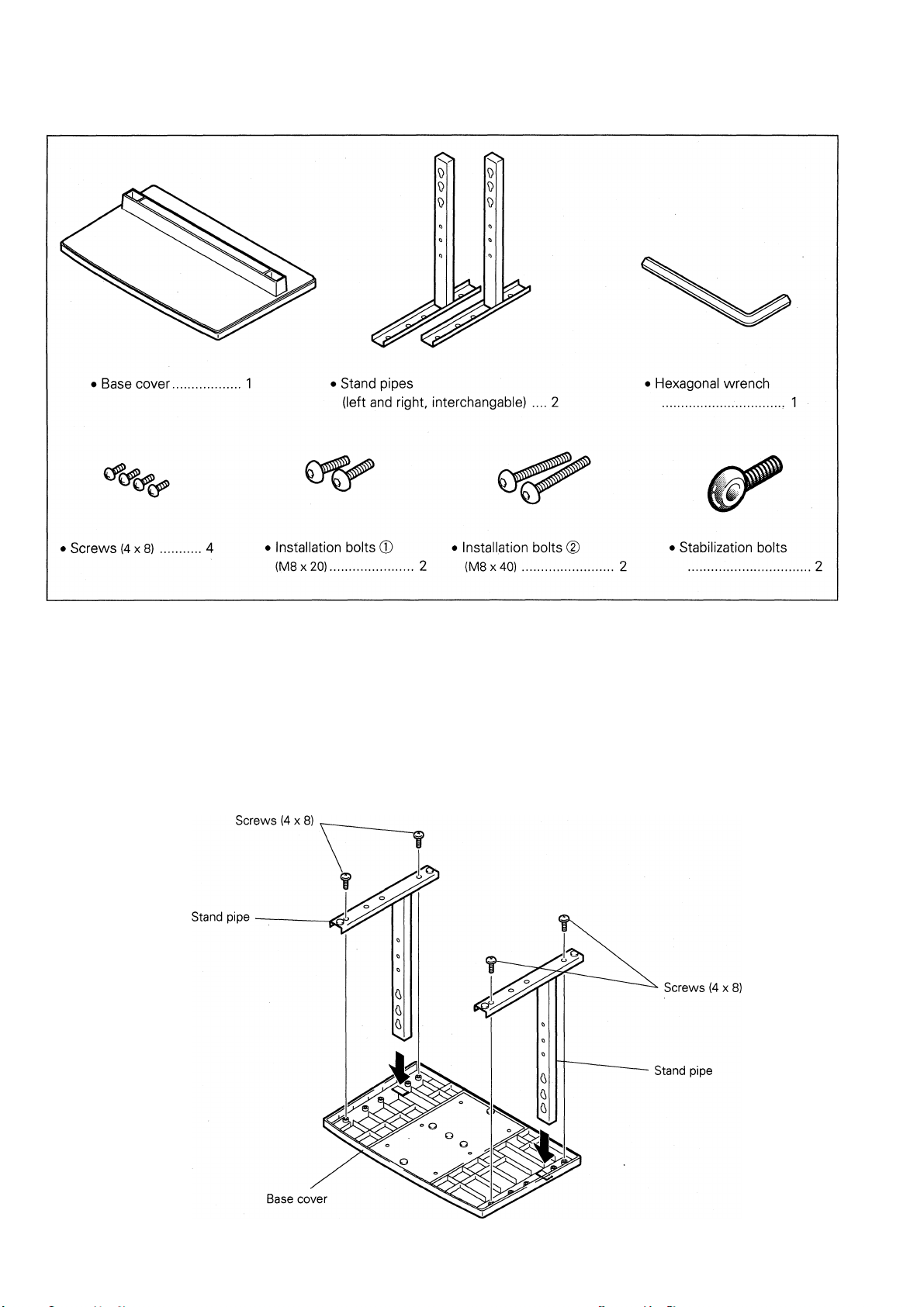
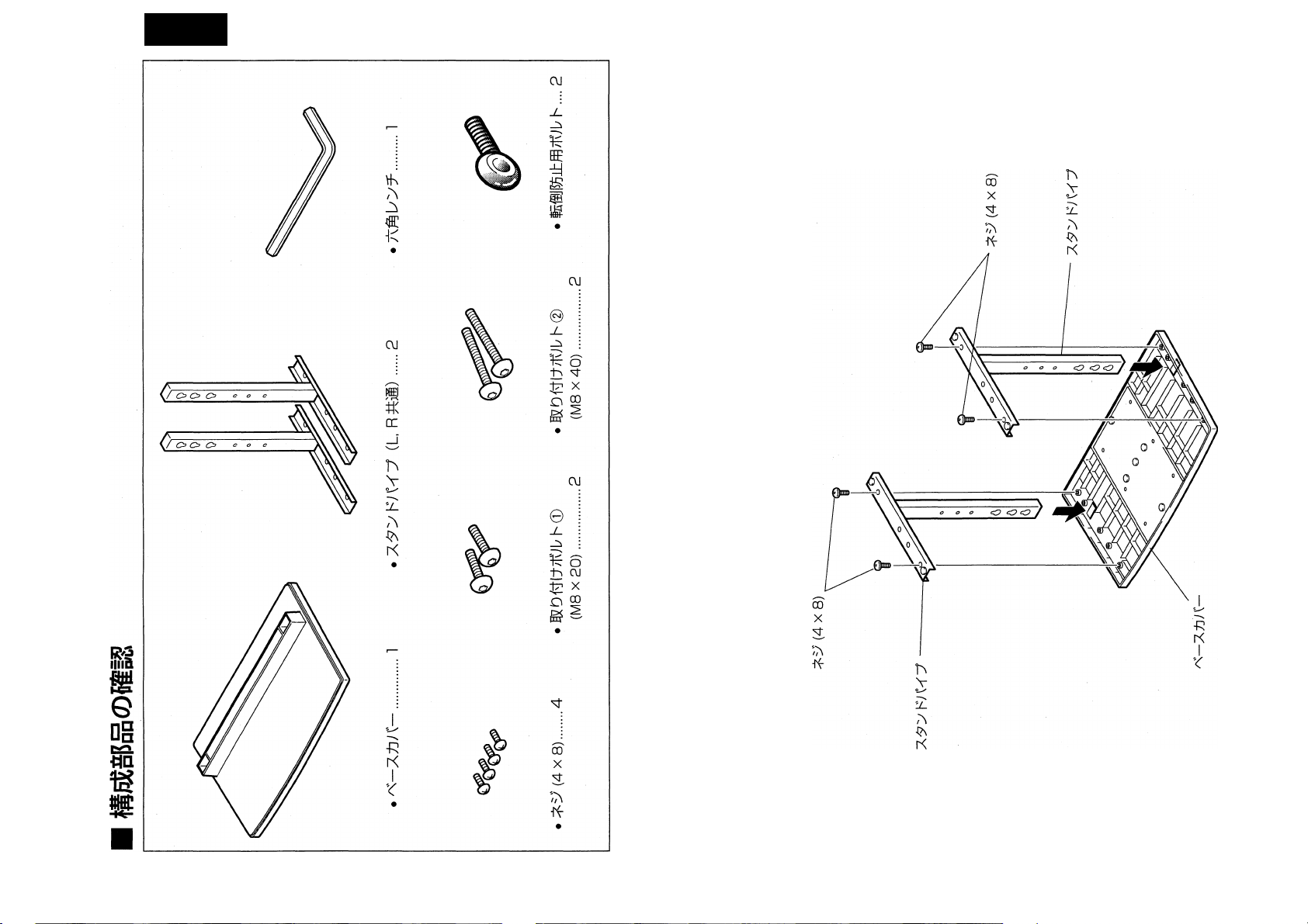
Check That You Have All the Parts
1. Stand assembling
■ Assembling Steps
1. Turn the base cover over so the underside is facing up.
2. Insert the stand pipes into the base cover.
3. Use the included screws to stabilize the stand pipes.
10
Page 11
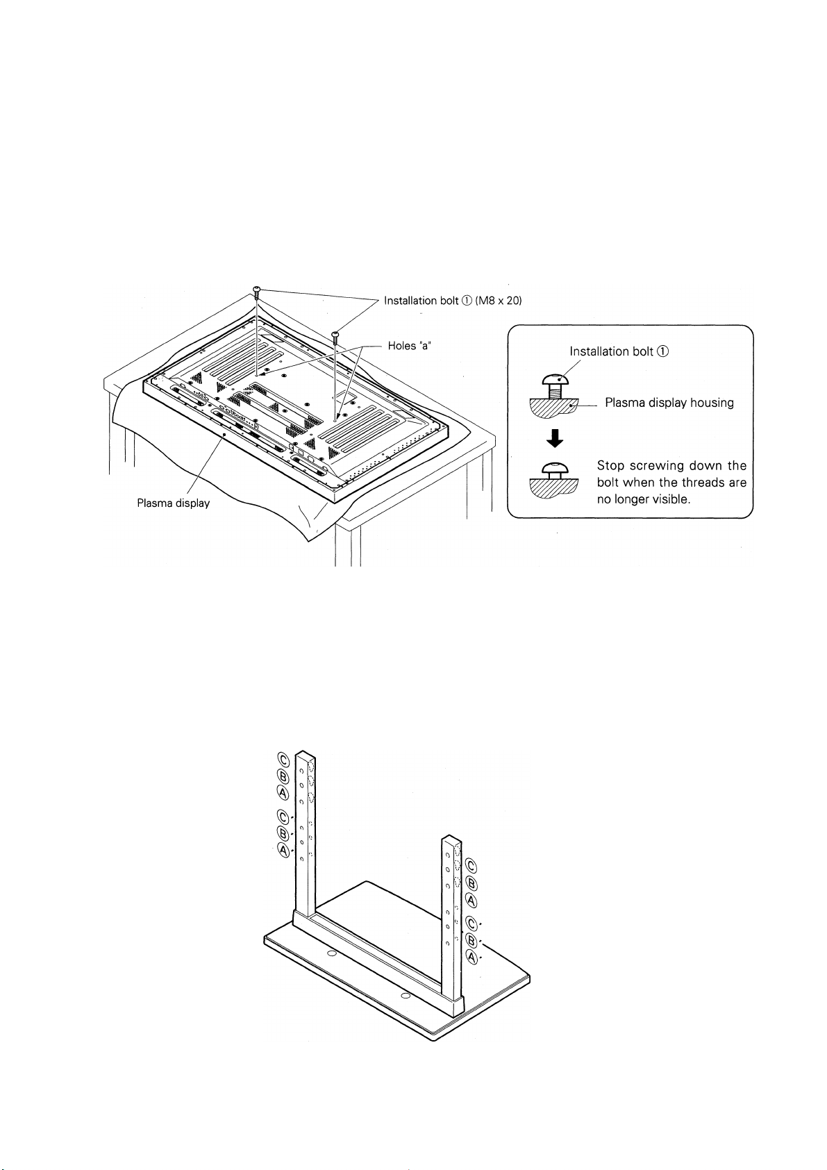
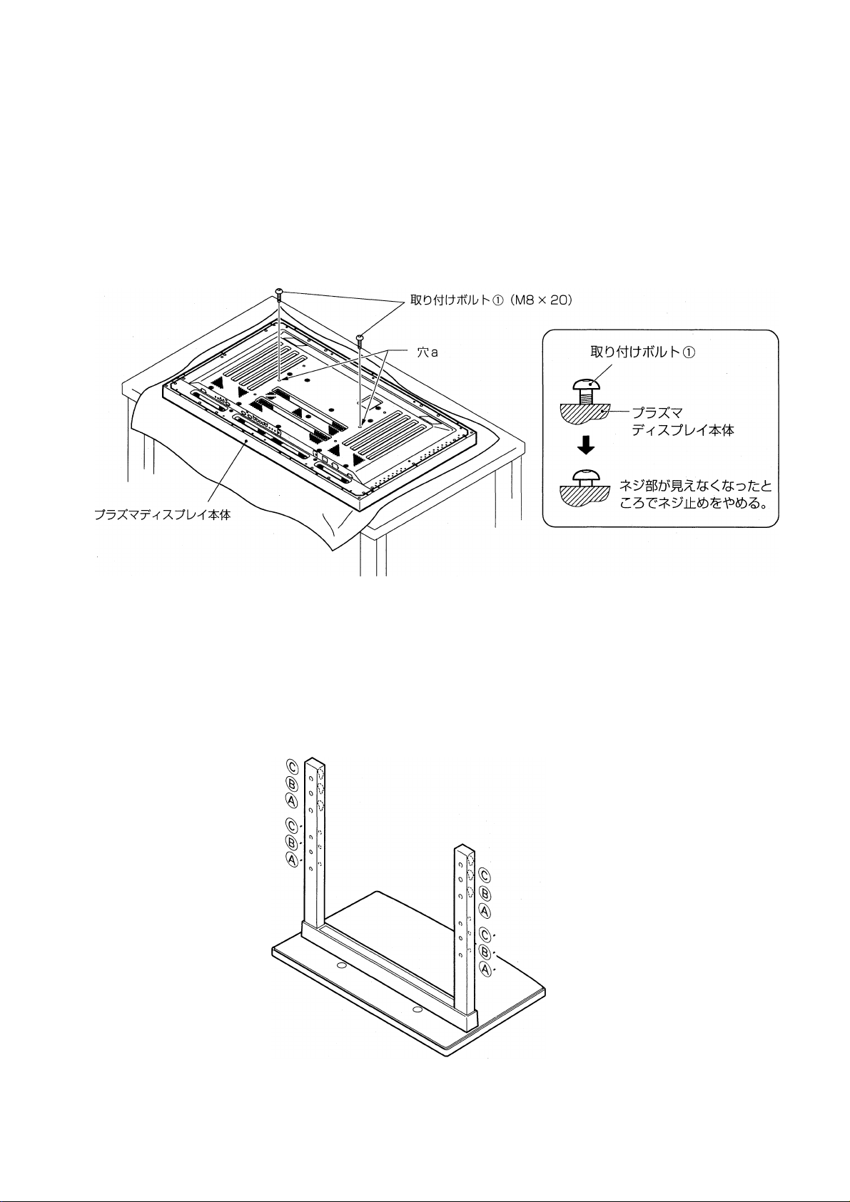
2. Stand attaching to the Plasma Display
■ Normal Installation
Step 1. With the plasma display lying flat, insert and secure the two Installation bolts ® (M8 x 20)
in the holes "a” located in the plasma display housing.
At this point, tighten these bolts ® only until the threads are no longer visible when
viewed from t he side (you will be unable to attach the display if the bolts are screwed in
completely).
Regarding the stand pipe screw holes when the stand is used as a desktop stand
Stan(j pipe screw holes when the sta nd is us ed as a (desktop stand
• Specifications........................................................ Nornnal use
• Screw holes used with stand orientation
Note: Screw holes ®, ®', © and ©' are for attaching options available separately.
..............
®, (§)'
11
Page 12
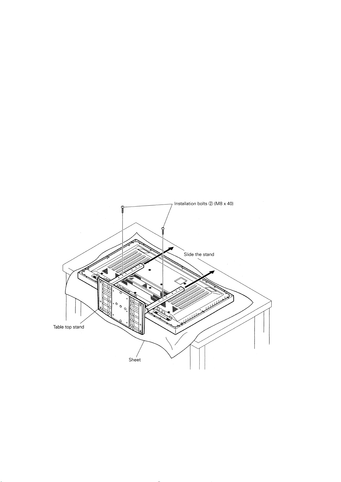
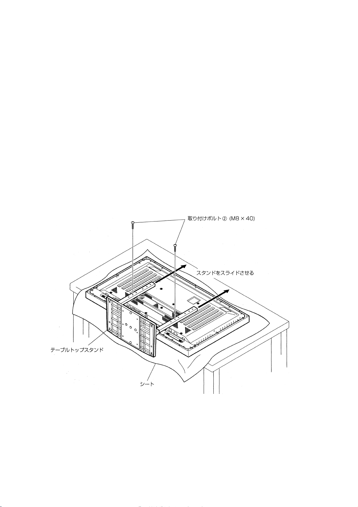
Step 2. As shown in figure, hook the stand pipe holes (§) onto the screw heads of the installation
bolts ©, then slide the stand upwards to the main plasma display until it engages the
installation bolts ® (once put together with the display, the stand will slides no more
than 19 mm (3/4 inch)).
Step 3. Pass the installation bolts @ (M8 x 40) through the stand pipes and tighten the installa
tion bolts securely with the included hexagonal wrench (holes should be used in the
proper, (B), (§)■).
Step 4. Tighten the installation bolts ® securely with the hexagonal wrench provided.
1. Place a sheet or protective cover to protect the (display from scratches or (damage.
A
Notes
2. Assemble only with the plasma display lying flat on a table or similar surface.
3. Do not apply excessive pressure and tighten the bolts more than necessary.
4. Move the stand so that the stand screw holes and the nuts that connect the main display line up correctly.
5. The display weighs approximately 40 kilograms (88 lb.) and has little depth, making the display very unstable.
For this reason, at least two people are required for setup and installation.
12
Page 13
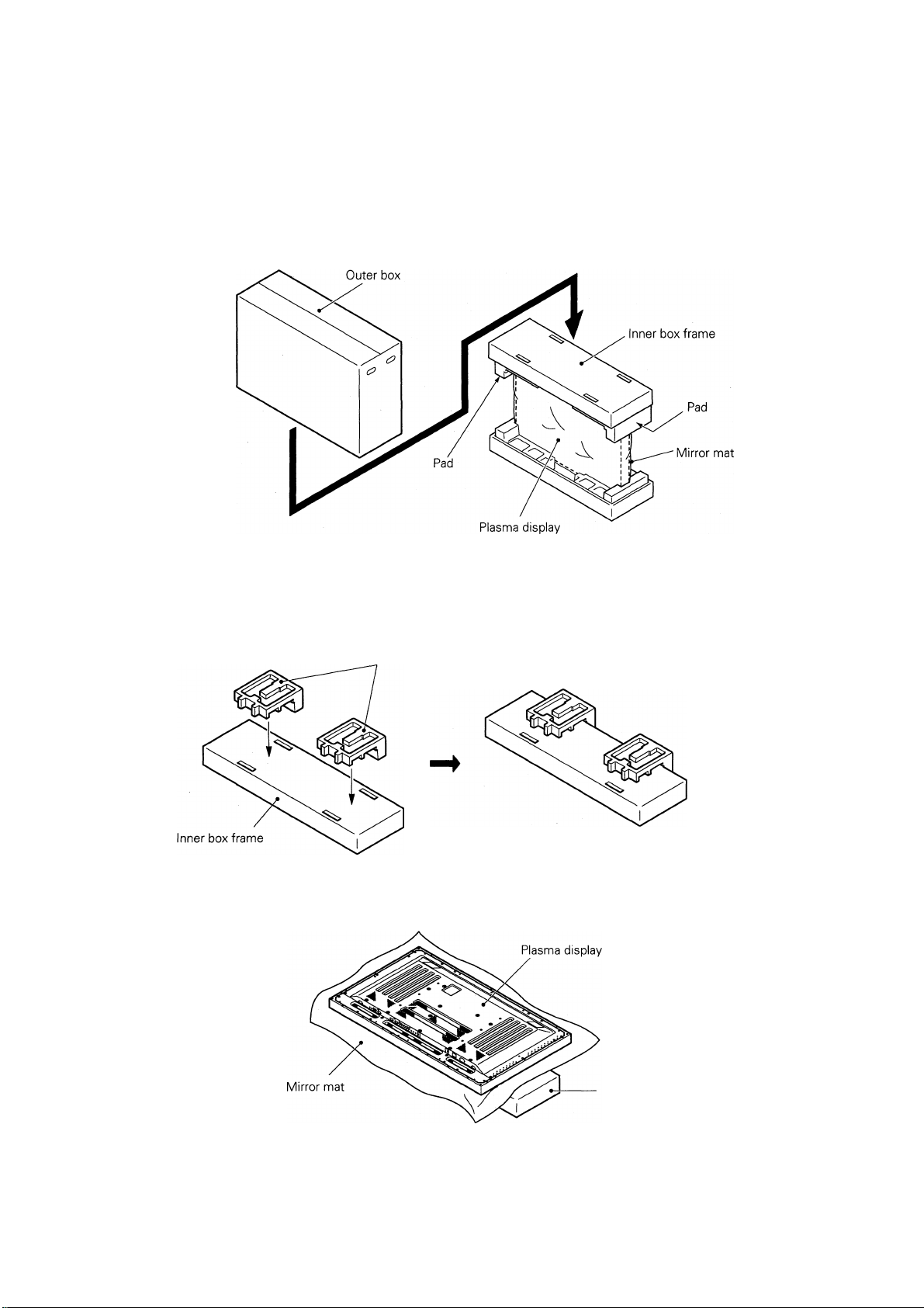
I
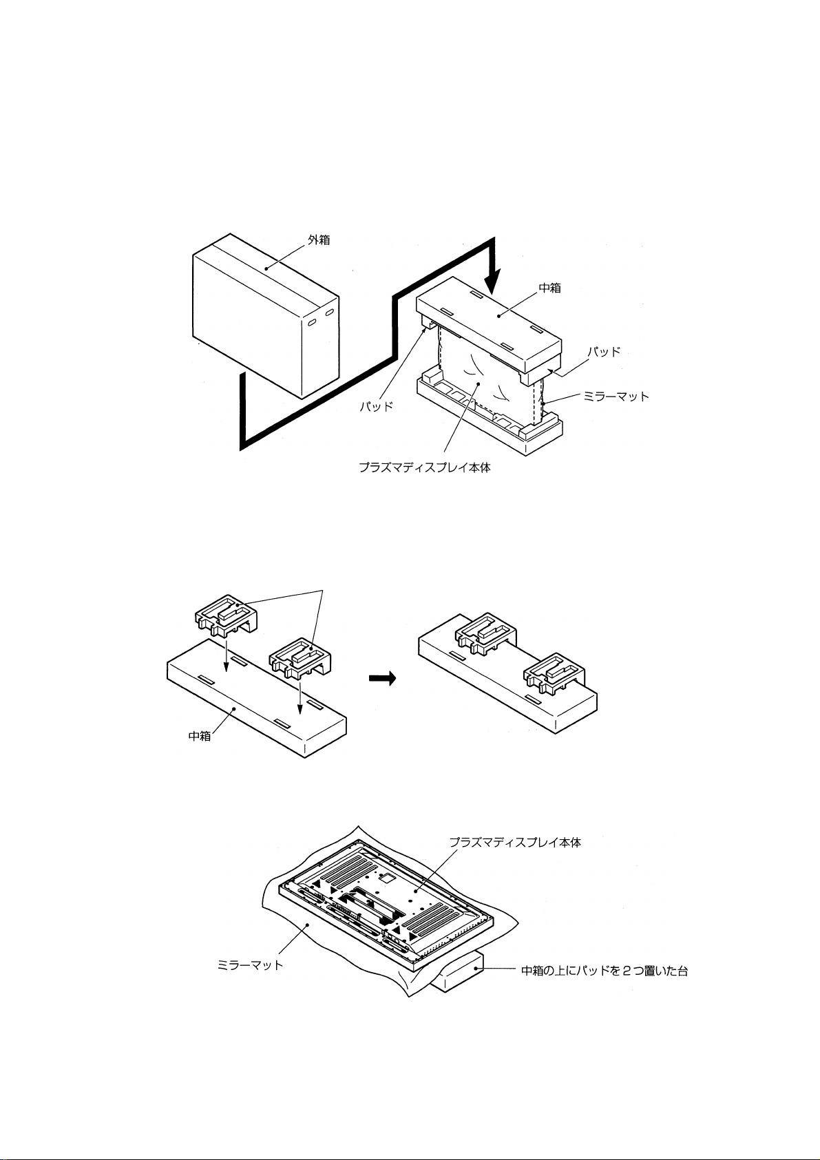
Instructions for using the main display packing material as a stand
for the working on the display
Main plasma display packaging setup
Step 1. Construct the stand for the plasma display using the inner box frame and pads shown in
the figure above (all pads are identical).
Raids
Step 2. Set the plasma display down on the pads as shown in the figure below.
Inner box franne topped by two pads
Step 3. Follow the instructions in Steps 1-4 in "Normal Installation" to attach the stand to the
plasma display.
13
Page 14
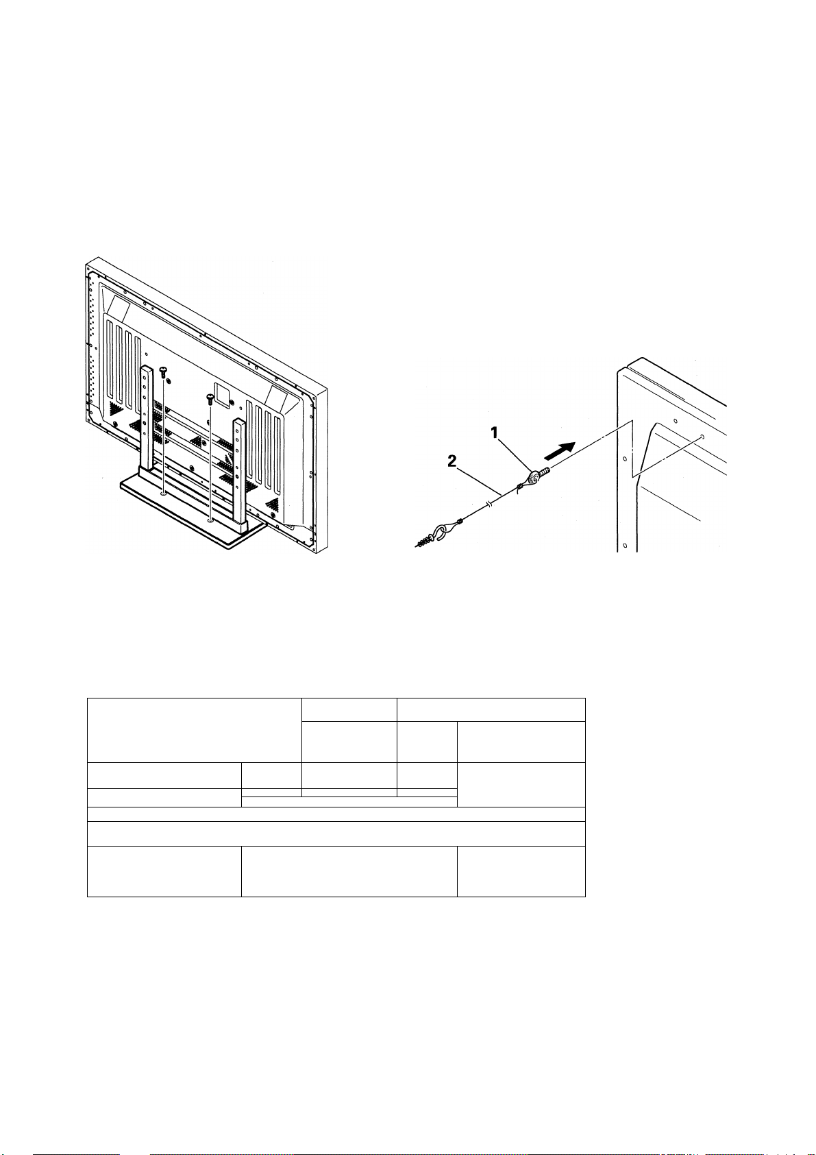
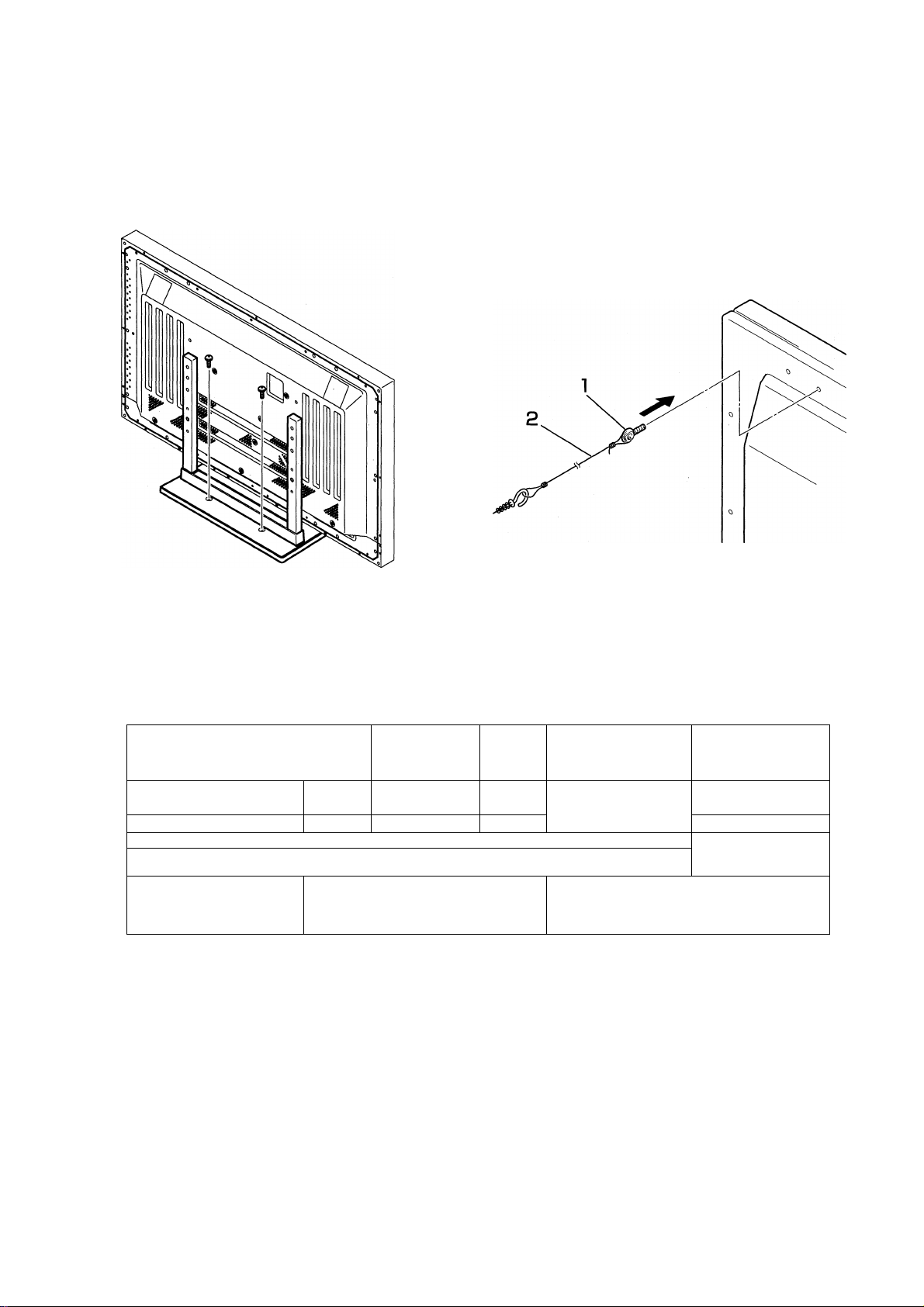
3. After assembling, connect the stand to the floor to prevent from falling over.
■ Stabilizing to the floor
• Use screws (sold separately) to attach and stabilize the
stand.
■ How to use the stabilization bolts
1. Attach the included bolts that prevent the display, from
falling over.
2. Stabilize the display by connecting to a wall or standing
beam with a strong cord.
(Repeat the same steps in the laterally direction to stabi
lize the assembly to the left and right.)
Use cord and hooks that are available on the market (sold sepa
rately).
Installation coordinates for screws used to stabilize the stand to the floor
* When stabilizing the stand to the floor, use M6 with a length above 20 mm (25/32 inch).
Units: mm (inch)
248 (9-3/4)
II
a
^ \ \ I I \
B II ^^l
) I
485(19-3/32)
J
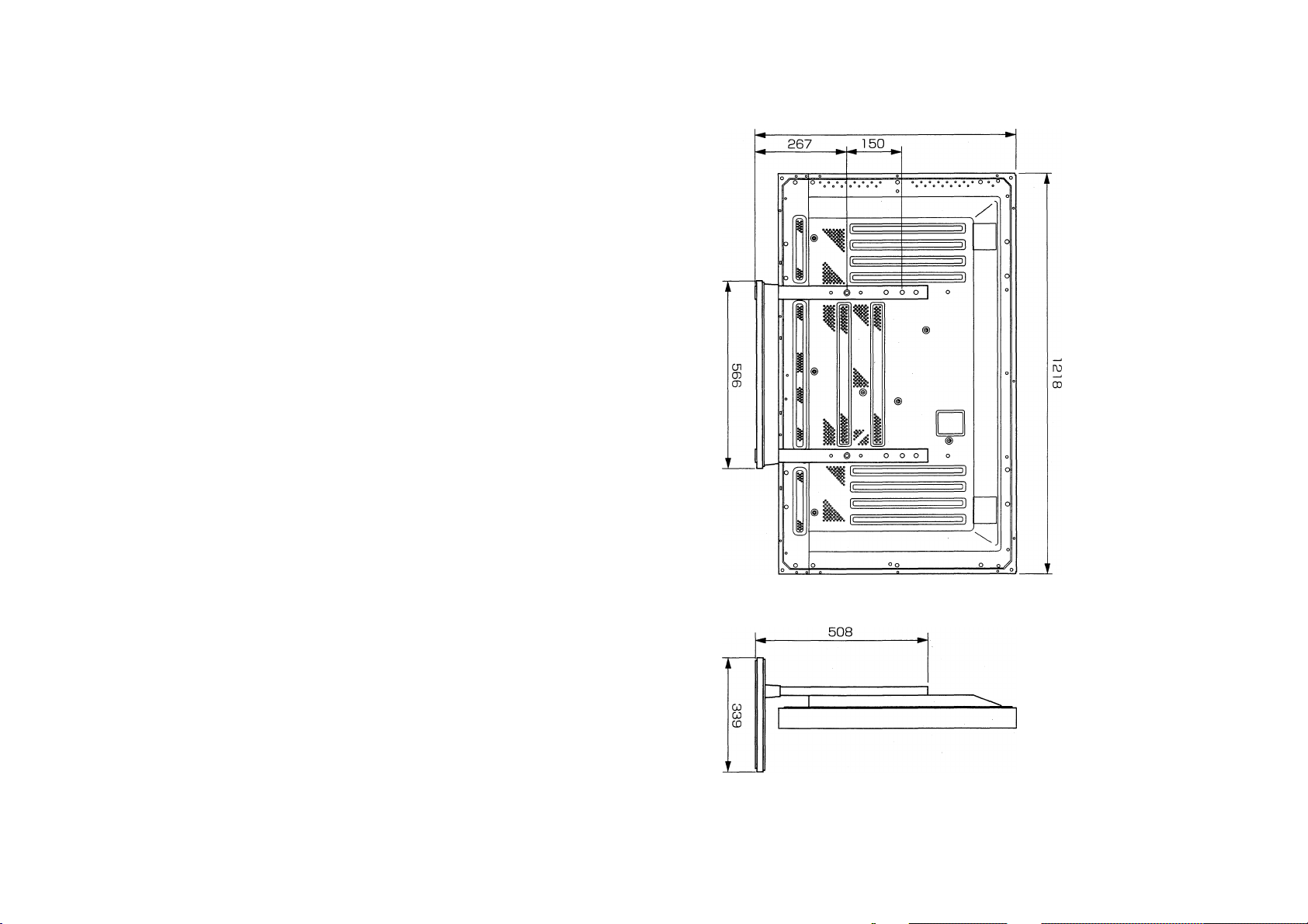
Specifications
Dimensions
.....
566 (W) X 508 (H) X 339 (D) mm
(22-9/32 (W) X 20 (H) x 13-11/32 (D) in/
14
Weight.................................4.0 kg (8.82 lb)
.................................42.9 kg (94.58 lb) (when the plasma display is attached)
Page 15
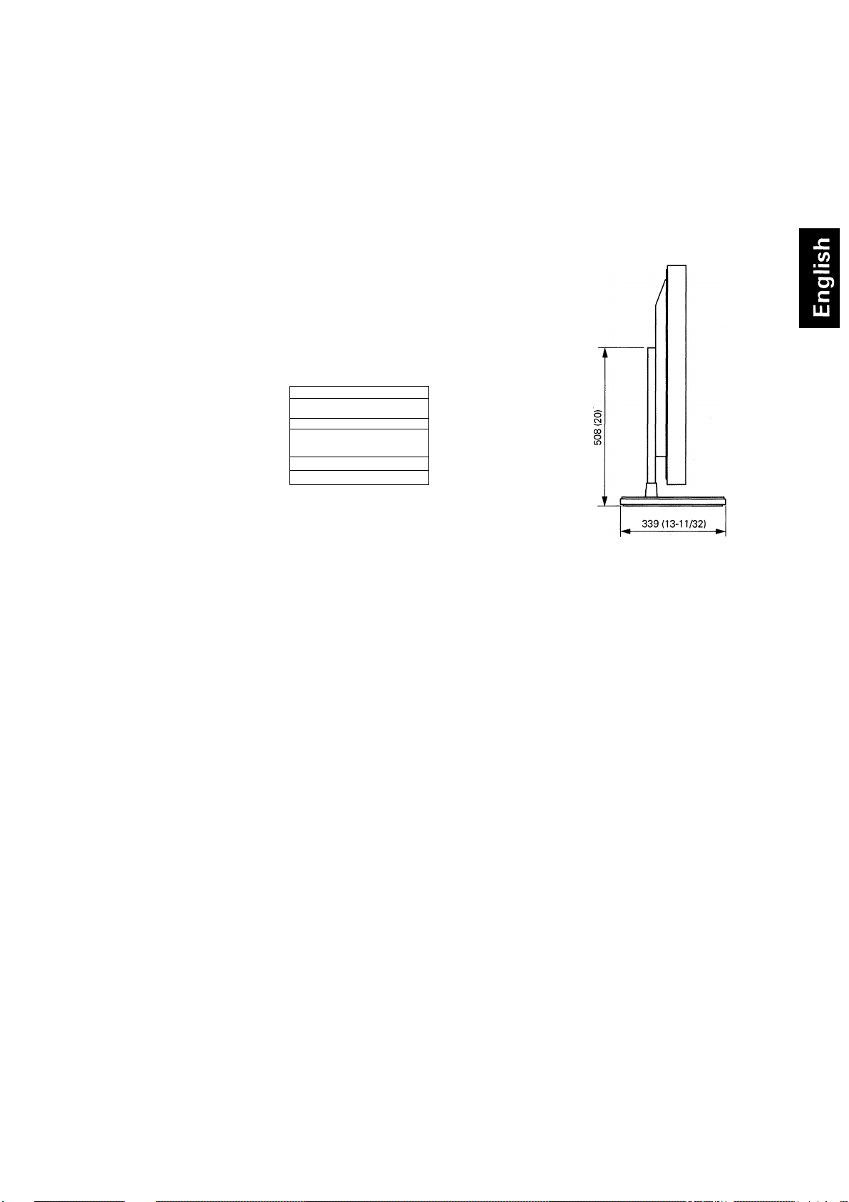
Dimensions Diagram
Units: mm (inch)
Normal use
1218(47-15/16)
IlS««»'
w
[(4WW9X
[(5m
--------
mm—
______g_____L___
------------_________
-¿5flfl588SCl)
assn
566 (22-9/32)
Published by Pioneer Corporation.
Copyright © 2001 Pioneer Corporation.
All rights reserved.
15
Page 16

Merci d'avoir choisi ce produit pioneer.
Nous vous invitons à lire les informations utiles à l'utilisation
et à l'installation de ce produit. Apres avoir lu attentivement
ces instructions, ranger les soigneusement afin de vous en
servir pour de futures références.
^ Attention
Ce signe symbolise un risque ou un danger qui peut
provoquer des blessures ou des dégâts matériels.
Installation
• Consultez votre distributeur si vous rencontrez quelque
difficulté avec cette installation.
• Pioneer décline toute responsabilité en cas de mauvaise
installation et utilisation, de modification ou de catastro
phes naturelles.
Attention Jk
1. Ce support de dessus de table est exclusivement conçu
pour l'affichage de plasma fabriqué par pioneer.
2. N'utilisez ce support pour aucun affichage de plasma ou
dans un but non indiqué. Ce support ne devrait pas être
modifié, mais seulement utilisé pour des affichages de
plasma.
3. Une mauvaise installation provoquerait la chute du.sup
port, causant de sérieuses blessures. Assurez-vous que
l'affichage de plasma se trouve à plat pendant que vous
le reliez à l'affichage principal.
4. Emplacement de l'installation
(a) Assurez-vous d'installer le support dans un endroit
qui peut largement supporter le poids combiné du
support et de l'affichage.
(b) Cet emplacement devrait-être une surface
complètement plate et stable.
Prenez les précautions nécessaires en installant le
support pour s'assure que le poids de l'affichage
est également réparti dans tout le support.
(c) N'installez pas ce support dehors, près d'un cou
rant chaud ou d'une plage.
(d) Installez ce support dans un endroit à l'abri des vi
brations ou des chocs.
5. (a) Assemblez le support suivant toutes les instructions
et le stabiliser solidement avec des vis à tous les
emplacements indiqués.
Après l'installation de l'affichage, la chute du sup
port a causé des dégâts dans certains cas ou dans
des situations similaires.
(b) Pour s'assurer de la bonne installation de l'affichage,
elle devrait être faite par plus de deux personnes.
(c) Avant l'installation, coupez le courant pour l'affichage
et les périphériques, puis retirez la prise de cordon
de secteur de la prise de courant.
16
Page 17
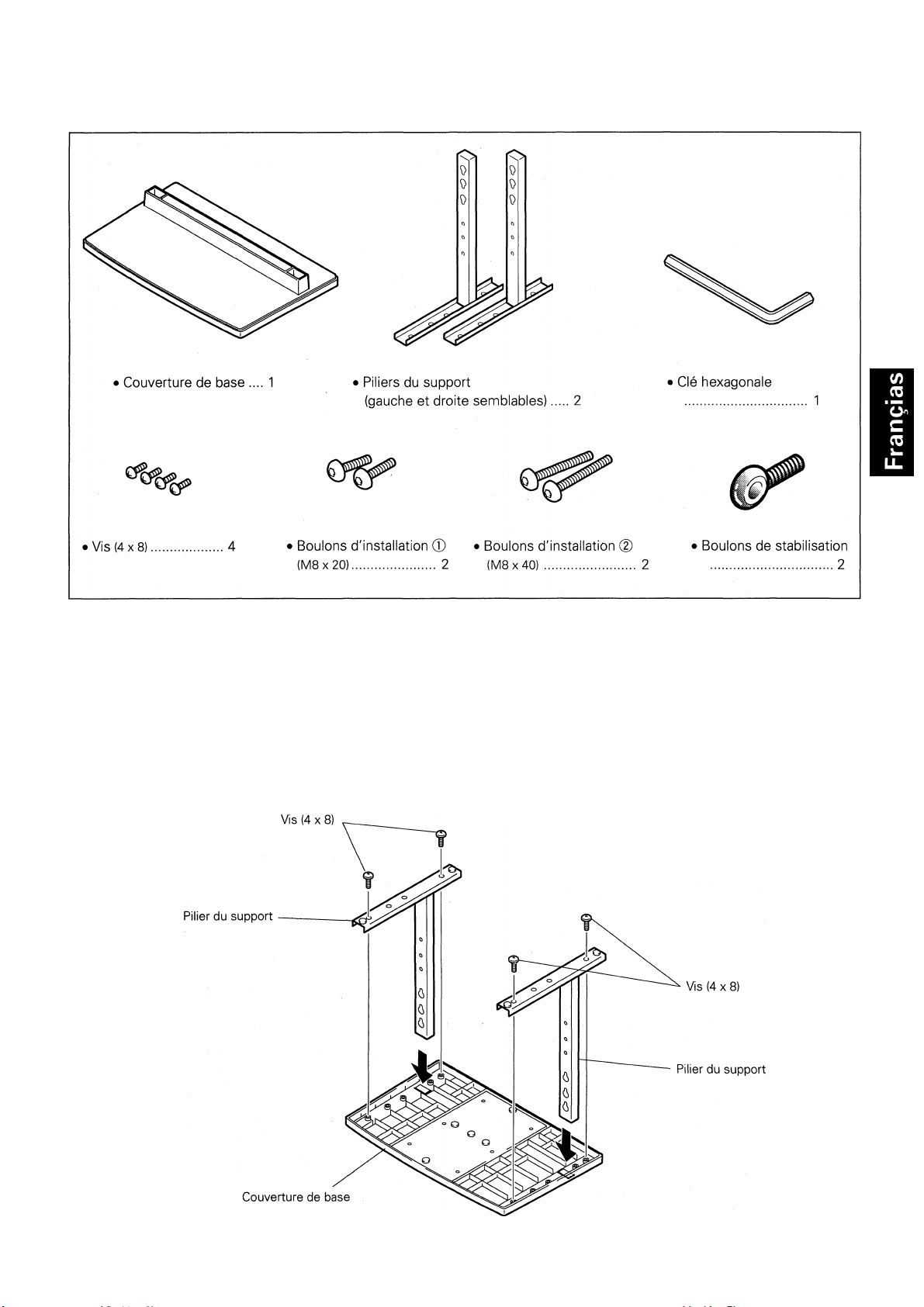
Vérifiez que vous avez toutes les pièces
1. Assemblement du support
■ Etapes d'assemblement
1. Tournez la couverture de base afin que le côté en dessous fasse face vers le haut.
2. Insérez les piliers du support dans la couverture de base.
3. Utilisez les vis incluses pour stabiliser les piliers du support.
17
Page 18
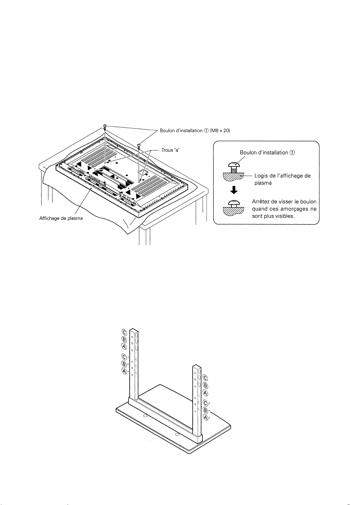
2. Support de l'affichage de plasma
■ Installation normale
Etape 1. Avec l'affichage de plasma se trouvant à plat, insérez et fixez les 2 boulons d'installation
® (M8x20) dans les trous "a" situés dans le logis de l'affichage de plasma.
A ce point, serrez ces boulons ® seulement jusqu'à ce que les amorçages ne soient plus
visibles, vu du côté (Vous ne pourrez pas attacher l'affichage si les boulons sont
complètement vissés).
Vision des trous de vis du pilier du support quand ce dernier est utilisé comme support de
surface de table.
Jrous de vis du pilier du support quand ce dernier est utilisé comme support de surface de table.
• Spécificités
• Trous de vis utilisés avec l'orientation du supportd)'
Note : Trous de vis ®, ®', © et ©' sont des options liées disponibles séparément.
..................................................................
Utilisation normale
18
Page 19
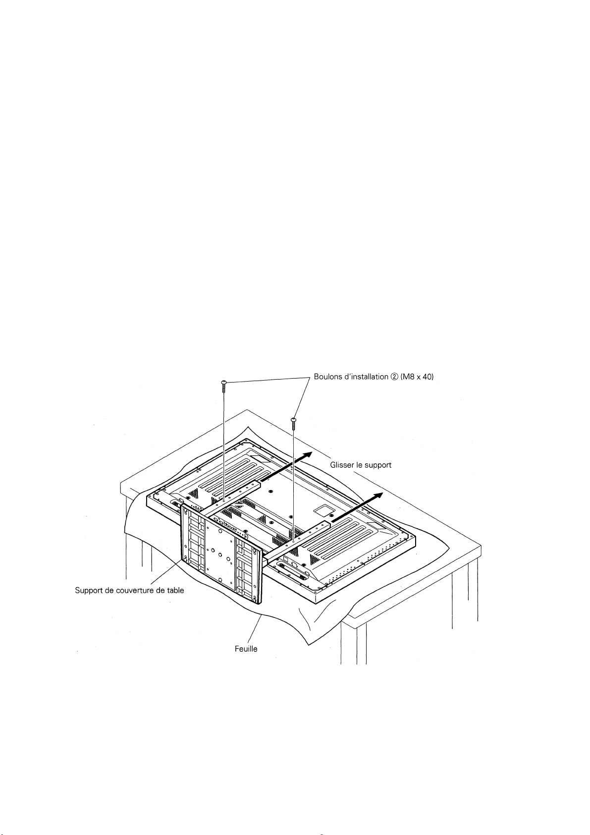
Etape 2, Comme représenté sur la figure, accrochez les trous de piliers du support (g) sur les têtes
de vis des boulons d'installation ®. Puis glissez le support vers le haut à l'affichage de
plasma principal jusqu'à ce qu'il engeance les boulons d'installation ® (une fois assemblé
avec l'affichage, le support ne glissera pas plus de 19 mm).
Etapes. Passez les boulons d'installation (g) (M8x40) par les piliers du support et serrez-les
proprement avec la clé hexagonale (Les trous utilisés sont (g) et (g)').
Etape 4. Serrez les boulons d'installation ® avec la clé hexagonale fournie.
1. Mettez une feuille ou une couverture (de protection pour protéger l'affichage (des égratignures et des dégâts.
A
Notes
2. Réunissez les différents pièces seulement avec l'affichage de plasma se trouvant à plat sur une table ou une
surface similaire.
3. N'appliquez pas trop de pression et ne serrez pas les boulons plus que nécessaire.
4. Déplacez le support de sorte que ses trous de vis et les écrous qui relient l'affichage principale s'alignent
correctement.
5. L'affichage pèse environ 40 kg, et a peu de profondeur, rendant l'affichage très instable. De ce fait, il faut au
moins deux personnes pour l'installation.
19
Page 20
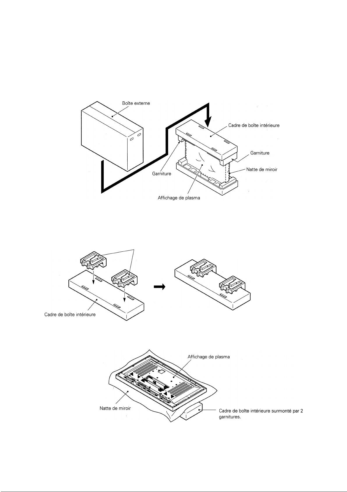
■ Instructions pour l'usage du matériel d'emballage de l'affichage
principal comme un support pour le travail sur l'affichage
Empaquetage de l'affichage principal de plasma
Etape 1. Construisez le support pour à l'aide du cadre de boîte intérieure et des garnitures
représentées sur la figure ci-dessus (toutes les garnitures sont identiques).
Garnitures
Etape 2. Placez l'affichage de plasma vers le bas sur les garnitures comme représenté sur la fig
ure ci-dessous.
Etape 3.
20
Suivez les instructions dans les étapes 1-4 dans "installation normale" pour rattacher le
support à l'affichage de plasma.
Page 21

3. Après le rassemblement des différentes
parties, reliez le support au sol afin d'éviter sa
chute.
■ Fixation au sol
• Utilisez des vis (vendues séparément) pour rattacher et fixer
le support.
■ Comment utiliser les boulons
de fixation
1. Reliez les boulons inclus qui empêchent l'affichage de
tomber.
2. Fixez l'affichage en le reliant à un mur ou un faisceau ver
tical à l'aide d'une corde solide.
(Répétez les mêmes étapes latéralement pour fixer
l'assemblage à gauche et à droite)
Utilisez la corde et les crochets qui sont disponibles sur le
Coordination de l'installation des vis utilisées pour fixer le support au sol
*Pendant que vous fixez le support au mur, utilisez M6 avec une longueur au-dessus de 20 mm.
Unités: mm
248
485
Spécificités
Dimensions
.......................
566 (W) x 508 (H) x 339 (D) mm
Poids...................................4.0 kg
.................................
42.9 kg (Quand l'affichage de plasma de est rattaché)
21
Page 22

Dimensions du schéma
Unités: mm
Utilisation normale
1218
22
Publication de Pioneer Corporation.
©2001 Pioneer Corporation.
Tous droits de reproduction et de
traduction réservés.
Page 23

Wir bedanken uns bei Ihnen für den Kauf dieses Pioneer
Produktes.
Bitte lesen Sie diese Bedienungsanleitung aufmerksann durch
um Ihr Produkt entsprechend benutzen zu können. Nachdem
Sie die Bedienungsanleitung gelesen haben, legen Sie sie
beiseite.
Vorsicht
Dieses Symbol weist auf Gefahr oder unsicheren
Gebrauch hin, was zu Verletzungen und Schaden führen
kann.
Installation
• Bei Schwierigkeiten bei der Installation wenden Sie sich
bitte an Ihrem Händler.
• Pioneer trägt keine Verantwortung für die Schaden die
durch unvorschriftsmäßige Installation, Benutzung und
Modifikation oder durch Naturkatastrophen angerichtet
wurden.
Vorsicht ^
Dieses Tischgestell wurde ausschließlich für dieses
Plasma Display von Pioneer entworfen.
Wenden Sie das Tischgestell nicht zu anderem Plasma
Display, oder zu anderem Zweck an, der nicht spezifiziert
ist. Das Tischgestell darf nicht modifiziert werden, und
darf nur zu Plasma Displays benutzt werden.
Zufolge einer unvorschriftsmäßigen Installation könnte
3.
das Gestell Umstürzen und schwere Verletzungen
anrichten. Vergewissern Sie sich, daß das Plasma Dis
play waagrecht liegt, während Sie das Gestell an das
Plasma Display anschließen.
4.
Installationsort
(a) Vergewissern Sie sich, daß Sie zur Aufstellung eine
Fläche finden, die das gesamte Gewicht des
Gestells und Plasma Displays halten kann.
(b) Die Fläche zur Aufstellung sollte waagrecht und
stabil sein. Seien Sie bei der Aufstellung vorsichtig
genug, daß sich das Gewicht des Displays am
Gestell gleichmäßig verteilt.
(c) Vermeiden Sie es unbedingt das Display an einem
Ort aufzustellen, wo das Gerät direktem
Sonnenlicht, hoher Luftfeuchtigkeit ausgesetzt wird.
(d) Vermeiden Sie es unbedingt das Display an einem
Ort aufzustellen, wo das Gerät Vibrationen oder
möglichem Stoß ausgesetzt wird.
5. (a) Aller Instruktionen nach stellen Sie das Gestell
zusammen, und stabilisieren Sie es mit den
Schrauben an jeder angegebenen Stelle. Es kam vor,
daß wegen Umstürzung des Gestells oder ähnlichen
Situationen nach der Aufstellung Schaden
enstanden.
(b) Bei der Aufstellung braucht man mehr als zwei
Menschen damit die Installation einwandfrei
auszuführen ist.
(c) Vor der Installation schalten Sie das Gerät aus, und
trennen Sie es von der Wandsteckdose ab.
23
Page 24

Kontrollieren Sie, daß Sie über alle Komponenten verfügen
1. Der Zusammenbau des Gestells
■ Schritte des Zusammenbaus
1. Drehen Sie die Unterlage aufwärts.
2. Stecken Sie die Gestellröhre in die Unterlage.
3. Befestigen Sie die Gestellröhre mit den mitgelieferten Schrauben.
24
Page 25

2. Anschluß des Gestells an das Plasma Display
■ Normal Installation
Schritt 1. Wenn das Plasma Display waagrecht liegt, sollen Sie die zwei Senkkopfschrauben zur
Installation © (M8 x 20) in den Klemmen "a" befindlich an dem Gehäuse des Plasma
Displays anschließen und befestigen.
Da sollen Sie die Schrauben solange ziehen bis der Gang von der Seite nicht zu sehen ist
(Sie können das Display nicht anschließen wenn die Senkkopfschrauben völlig eingedreht
sind).
Senkkopfschrauben zur Installation ® (M8 x 20)
Senkkopfschrauben zur Installation ®
Hören Sie auf (die
Schrauben einzu(drehen,
wenn (der Gang nicht mehr
zu sehen ist.
Informationen über die Löcher der Gestellröhre wenn das Gestell als Tischgestell benutzt wird
Die Löcher (der Gestellröhre wenn (das Gestell als Tischgestell benutzt wir(d.
♦ Spezifikationen
• Schraubenlöcher benutzt mit (der Gestellsorientation... ® , ®'
Hinweis: Die Schraubenlöcher ®, ®', © unid ©' sin(d für (den Anschluß von Optionen (die separiert erhältlich s\nö .
..................................................................
Normaler Gebrauch
25
Page 26

Schritt 2. Laut der Abbildung hängen Sie die Löcher der Gestellsröhre (g) an den Köpfen der
Senkkopfschrauben zur Installation ®, dann schieben Sie das Gestell in Richtung Plasma
Display bis zu den Senkkopfschrauben zur Installation ®. (Nachdem Sie das Gestell an
das Plasma Display angeschlossen haben, wird das Schieben des Gestells höchstens 19
mm).
Schritt 3. Stecken Sie die Senkkopfschrauben (D (M8 x 40) in die Gestellröhre und drehen Sie die
Senkkopfschrauben zur Installation mit dem mitgelieferten hexangulären Schraubenzieher
ein. (Man sollte die Löcher in zusammengehörigen Paaren anwenden, (g) und (g)'.)
Schritt 4. Drehen Sie die Senkkopfschrauben zur Installation ® mit dem angegebenen hexangulären
Schraubenzieher.
1. Legen Sie ein Bettuch oder Schutzdeckel um das Display von Kratzen und Schaden zu beschützen.
2. Das Plasma Display darf nur waagrecht liegend auf einem Tisch oder ähnlichen Fläche zusammengebaut werden.
Hinweise 3. Üben Sie keinen großen Druck aus, und drehen Sie die Schrauben nicht fester als nötig.
4. Bewegen Sie das Gestell so, daß die Löcher der Gestellsröhre und die Schraubenköpfer, die es mit dem
Display verbinden, in einer Linie bleiben.
5. Das 40kg Gewicht und die kleine Tiefe machen das Display sehr instabil. Aus diesem Grund braucht man
wenigstens zwei Menschen um die Aufstellung und die Installation einwandfrei auszuführen.
26
Page 27

■ Instruktionen zur Benutzung des Packungsmaterials vom Display
als Unterlage für die Arbeit am Display
Zusammenbau der Packung vom Plasma Display
Schritt 1. Bauen Sie die Unterlage mit Hilfe des inneren Gestells des Kartons und der Stopfungen
für das Plasma Display zusammen nach der Abbildung (siehe oben) (alle Stopfungen
sind identisch).
Schritt 2. Legen Sie das Plasma Display auf die Stopfungen nach der Abbildung unten.
Schritt 3. Folgen Sie die Instruktionen in den Schritten 1-4 in "Normale Installation" um das Gestell
an das Plasma Display anzuschließen.
27
Page 28

3. Befestigen Sie das Gestell nach dem Zusammenbau zum Boden um die Umstürzung zu vermeiden.
I Befestigung zum Boden
Benutzen Sie Schrauben (separiert erhältlich) zum Anschluß
und zur Befestigung des Gestells.
■ Wie benutzt man die
Senkkopfschrauben zur
Stabilization
1. Drehen Sie die mitgelieferten Senkkopfschrauben zur Sta
bilization, die Umstürzung vermeiden.
2. Befestigen Sie das Display mit einem starken Draht zur
Wand oder einem Gestell. (Wiederholen Sie die gleiche
Schritte in Richtung beider Seiten um das Gerät auch links
und rechts zu stabilisieren.)
Benutzen Sie Draht und Haken erhältlich auf dem Markt
Installationskoordinaten für die Schrauben die man zur Stabilisierung des Gestells auf dem Boden benutzt
^Benutzen Sie Schrauben M6 länger als 20 mm bei der Stabilisation des Gestells auf dem Boden.
Einheiten: mm
248
S\)
c
485
■ Technische Daten
Abmessungen
Poids...................................4.0 kg
...................................
................ 566 (B) x 508 (H) x 339 (T) mm
42.9 kg (wenn das Plasma Display angeschloßen ist))
28
Page 29

Diagramm der Abmessungen
Einheiten: mm
Normaler Gebrauch
1218
Veröffentlicht von Pioneer Corporation.
Urheberrechtlich geschützt © 2001 Pioneer Corporation.
Alle Rechte Vorbehalten.
29
Page 30

La ringraziamo per aver acquistato questo prodotto di Pioneer.
La preghiamo di leggere attentamente le istruzioni di uso per
sapere come usare corettamente il suo modello. Dopo di aver
letto le istruzioni, metterle in un posto sicuro per un futuro
riferimento.
^ Avvertenze
Questo sìmbolo sì riferisce ad uso pericoloso che può
risultare danni personali o deterioramenti.
Installazione
• Rivolgersi al proprio rivenditore in qualsiasi caso di difficoltà
durante l'installazione.
• Pioneer non ha alcunafesponsabilità per gli eventuali danni
in seguito a installazione incoretta, uso incoretto,
modificazione o disastro naturale.
Avvertenze Jk
1. Questo supporto di tavolo é stato esclusivamente
progettato per il display di plasma prodotto da Pioneer.
2. Non usarlo per nessun altro display di plasma o per altri
scopi non specificati. Il supporto non può essere modificato
e può essere usato solo per display di plasma.
3. Installazione incoretta può risultare la caduta del supporto
e causare severi danni. Accertarsi se il display di plasma
sia messo in posizione orizzontale mentre si attaca il
supporto al display principale.
4. Posto deH'installazione
(a) Verificare se si installa il supporto in un posto reggente
il peso totale del supporto e display.
(b) Il posto dell'installazione deve essere perfettamente
fiat e di superfice stabile. Verificare con precauzione
se durante il montaggio il peso del display sia
distribuito ugualmente fra le parti del supporto.
(c) Non installare questo supporto fuori, pressi sorgenti
caldi o vicino a spiaggia.
(d) Non installare questo supporto nei posti dove può
essere esposto di vibrazione o elettrocuzione.
5. (a) Montare questo supporto seguendo le istruzioni e
fissarlo bene con le viti nei posti indicativi. In alcuni
casi dopo l'installazione del display possono causarsi
dei danni derivanti dalla caduta del supporto o dai simili
situazioni.
(b) Per essere sicuri che il display é installato
sicuratamente, l'operazione deve essere fatta da più
di due persone.
(c) Prima l'installazione scollegare l'allimentazione per il
display e gli accessori esterni, quindi rimuovere i cavi
di allimentazione e le spine dall'alimentazione d'uscita.
30
Page 31

Verificare se avete tutte le parti
1. Montaggio del supporto
■ Montaggio
1. Girare la copertura di base con la parte inferiore sopra.
2. Inserire le rotaie del supporto nella copertura di base.
3. Usare le viti fornite per fissare le rotaie.
Rotaie del supporto
31
Page 32

2. Attacamento del supporto al Display di Plasma
■ Installazione normale
Passo 1. Con il display di plasma appoggiato in orizontale inserire e fissare i due ribattini di
installazione © (M8x20) nei fori "a" situati nella copertura del display di plasma.
A questo punto serrare i ribattini ® finché non siano più visibili dalla vista laterale (non é
possibile attacare il display se i ribattini sono completamente avvitati).
I fori di viti sulle rotaie quando il supporto é usato come supporto di desktop
I fori di viti sulle rotaie quando il supporto é usato сопле supporto di desktop.
• Specifiche
• Fori di viti usati
Nota: Fori di viti (
.....................
..............
Uso normale
®, ®'
) e ©' sono per attacare opzionali separatamente disponibili
32
Page 33

Passo 2. Come mostra la figura, ganciare le teste di vite dei ribattini di installazione nei fori (g)
delle rotaie, quindi far scorrere il supporto verso il principale display di plasma finché
non si inseriscano i ribattini di installazione ® (una volta messisi insieme con il display, il
supporto non scorrerà più di 19 mm)
Passo 3. Far passare i ribattini per le rotaie e serrare sicuramente i ribattini con la brugola fornita
(i fori vengono usati con le proprie ®, (g)').
Passo 4. Serrare i ribattini ® sicuramente con la brugola fornita.
1. Mettere una lenzuola o copertura di protezione per evitare i danni e i graffi sullo schermo.
2. Montarlo al display solo se quello sta in posizone orizzontale su un tavolo o slmile superfice con lo schermo In
Nota 9iù.
3. Non applicare pressione eccesiva o avvitare i viti di più di quanto é possibile.
4. Muovere il supporto in modo che i fori de vite e i dadi colleganti il display siano allienati correttamente.
5. Il display pesa cc. 40 kg e di poco spesso che rende il display molto instabile. Per questo motivo sono necessarie
almeno due persone per il montaggio e installazione.
33
Page 34

■ Istruzione per usare l'incartamento come appoggio a lavorare sul
display
Montaggio del pacco del display di plasma
Passo 1. Costruire il supporto per il display di plasma usando la sistemazione del pacco e gli
appoggi mostrati in figura di sotto (Tutti gli appoggi sono identici).
Appoggi
Passo 2. Mettere il display sugli appoggi come mostra la figura.
Passo 3. Seguire le instruzioni da 1-4 in "Installazione normale" per attacare il supporto al display
di plasma.
34
Page 35

3. Dopo il montaggio impostare il supporto sul pavimento per evitare la caduta
■ Stabilire sul pavimento
• Usare viti (non forniti) per attacare e stabilire il supporto.
■ Come usare ribattini di
stabizzazione
1. Attacare i ribattini forniti per evitare la caduta del display.
2. Stabilire il display collegandolo al muro o posizionandolo
con una forte corda.
(Ripetere gli stessi passi in direzione laterale per stabilire
il montaggio sia in destra che a sinistra.)
Usare corde e ganci disponibili nei negozi (si vendono
separatamente).
Cordinate dì installazione per viti usati a stabilire il supporto sul pavimento
*Quando si stabilisce il supporto per terra, usare M6 lunga cc 20 mm.
Unità: mm
Specifiche
Dimensione
........................
566 (L) x 508 (A) x 339 (P) mm
Peso
...................................
...............................................
4.0 kg
42.9 kg (quando il plasma é attacato)
35
Page 36

Diagramma di dimensione
Unità: mm
Uso normale
1218
36
Pubblicato da Pioneer Corporation.
Copyright © 2001 Pioneer Corporation.
Tutti i diritti reservati.
Page 37

Dank u wel voor het kopen van dit Pioneer produkt. Lees
alstublieft deze gebruiksaanwijzing door zodat u weet hoe u
uw model op een juiste manier moot laten functioneren. Nadat
u de instructies gelezen heeft, zet ze op een veilige plaats voor
latere verwijzing.
A WAARSCHUWING
Deze symbool duidt een gevaarlijke of onjuiste
functionering aan dat kan persoonlijke verwonding of
schade in het produkt veroorzaken.
Installatie
• Neem contact met uw handelaar op als u enkele
moeilijkheden met de installatie heeft.
• Pione^er is niet verantwoordelijk voor schade dat door
onjuiste installatie, onjuiste gebruik, modificatie of door
natuurramp veroorzaakt wordt.
WAARSCHUWINGEN A
1. Deze tafelstaander werd uitsluitend voor plasmaschermen
gepland die door Pioneer geproduceerd waren.
2. Gebruik deze staander niet voor een ander plasmascherm
of voor verschillende doelen die niet voorgeschreven zijn.
De staander mag niet veranderd worden en mag uitsluitend
voor plasmaschermen gebruikt worden.
3. De onjuiste installatie kan tot het omvallen van de staander
leiden en het kan serieuze verwonding veroorzaken. Wees
zeker dat het plasmascherm ligt wanneer u de staander
eraan voegt.
4. Locatie van installatie
(a) Vergewis u zieh ervan dat de staander op een plaats
neergezet wordt die geschikt is om het collectieve
gewicht van de staander en het scherm te houden.
(b) De plaats van de installatie moet volledig vlak en
stabiel zijn. Wees voorzichtig wanneer u de Stelling
installeert om te verzekeren dat het gewicht van het
scherm gelijkmatig verdeeld is op de staander.
(c) Installeer deze staander niet buiten, bij warmtebron
of dicht bij het strand.
(d) Installeer deze staander nergens waar het een ob
ject van vibratie of beving kan zijn.
5. (a) Stel de staander samen volgens alle Instructies en
stabiliseer de staander veliig met de schroeven op
de voorgeschreven plekken. Er waren al gevallen
wanneer na het installeren van het scherm er schade
werd veroorzaakt doordat de staander omgevallen
was of door andere situaties.
(b) Om het scherm veilig te installeren moet het voor de
zekerheid met meer dan twee personen gebeuren.
(c) Voor de Installatie zet het scherm en de
aangeschakelde middelen met power uit, daarna
trek de stekker uit het stopcontact.
37
Page 38

Controleer of u alie delen heeft
• Voetstuk ,
Schroeven(4x8)
.........
4
• Installatie schroeven © • Installatie schroeven @
(M8x20)
• Poten van de staander
(links en rechts verwisselbaar).... 2
.........
..............
2 (M8x40)........................... 2
1. Samenstelling van de staander
■ Stappen van samenstelling
1. Draai het voetstuk onn zodat de ondere kant boven is.
2. Voeg de poten aan het voetstuk.
3. Gebruik de inclusieve schroeven voor het stabiliseren van de poten.
Zeshoekige draai
► Stabiliseringsschroeven
................................2
......
1
38
Page 39

2. Staander aan het plasmascherm voegen
■ Normale installatie
Stap 1. Terwijl het plasmascherm neerligt, zet en verveilig de twee installatie schroeven © (M8x20)
in gaten "a" die op het omhuisel van het plasmascherm verplaatst zijn. Bij dit punt draai
deze schroeven © alleen aan totdat de draailijnen van het zijdegezien al niet meer zichtbaar
zijn (Als u de schroeven volledig indraait is het onmogelijk om het plasma scherm eraan
te voegen).
• Betreffend de schroefgaten van de staanderpoot als de staander als tafelstand gebruikt wordt.
Schroefgaten van de staanderpoot als de staander als tafelstand gebruikt wordt.
• Specificaties
• Schroefgaten gebruikt met Stelling orientatie... ®, ®'
Opmerking: Schroefgaten ®, ®', © en ©' zijn voor het aanvoegen van apart verkrijgbare luidsprekers.
..........................................................
Nornnaal gebruik
39
Page 40

Stap 2. Zoals het figuur het laat zien, haak de gaten van de staanderpoten (g) aan de schroefkoppen
van de installatie schroeven ®, daarna laat de staander boven glijden in de richting van
het plasmascherm totdat het de instaMatie schroeven ® aanraakt (als het met het scherm
samengesteld is, zai de staander niet meer dan 19mm glijden.)
Stap 3. verplaats de installatie schroeven (D (M8x40) door de staanderpoten en snoer de installatie
schroeven in met behulp van de zeshoekige draai (gaten zouden in de gepaste paren
gebruikt moeten worden, ®,
Stap 4. Snoer de installatie schroeven ® veilig in met de zeshoekige draai.
Zet een laken of een beschermen(d be(dekking neer om het schernn van schrammen of scha(de te beschermen.
1.
2.
Stel het plasmascherm samen alleen als het op een tafel of op een dergelijke oppervlak plat ligt.
Opmerkingen
Verzet geen hevige druk op de schroeven en snoer ze niet verder in dan dat het nodig is.
Beweeg de staander zo dat de schroefgaten en de moeren, die de staander aan het scherm verbinden, precies
4.
in een lijn staan.
Het scherm weegt ongeveer 40 kilogram en heeft een kleine diepte dat het scherm onstabiel maakt. Daarom
5.
eist het aanzetten en installeren tenminste twee mensen.
40
Page 41

■ Instructies voor het gebruik van de verpakking van het
hoofdscherm om het als staander laten functioneren
De werking van het plasmascherm verpakking
Stap 1. Stel een staander voor het plasmascherm samen, gebruik de binnenste lijst van de doos
en de opvulsels volgens het bovenstaande figuur (alle opvulsels zijn hetzelfde).
Opvulsel
Stap 2. Zet het plasmascherm op de opvulsels neer zoals het figuur het hieronder laat zien.
Binnenste lijst van de doos
getopt door twee opvulsels
Stap 3. Volg de instructies in stappen 1-4 onder de titel "Normale installaties" om de staander
aan het plasmascherm kunnen voegen.
41
Page 42

3. Nadat de staander samengesteld is, maak de staander aan de vioer vast zodat het niet omvalt.
■ Stabilisering aan de vioer
• Gebruik schroeven {worden apart verkocht) voor het
aanvoegen en stabiliseren van de staander.
■ Come usare ribattini di
stabizzazione
1. Maak de inclusieve schroeven vast dat het scherm van
het omvallen beschermt.
2. Stabiliseer het schernn door het aan de muur verbinden of
met een serke touw tegen een balk vastnnaken.
(Herhaal dezelfde stappen van de zijkant om de
Samenstelling van beide kanten te stabiliseren.)
Gebruik snoer en haken die op de markt te koop zijn (worden
Installatie coördinatas voor de schroeven die bij het stabiliseren
van de staander aan de vioer gebruikt worden.
*Als de staander aan de vioer gestabiliseerd wordt, gebruik M6 dat de lengte van 20mm heeft.
Eenheid : mm
248 485
I I
n
■ Specificaties
Dimensies
Gewicht...............................4.0 kg
..........................
..............
..................
566 (L) x 508 (A) x 339 (P) mm
42.9 kg (als het plasmascherm vastgemaakt is)
42
Page 43

Diagram van dimensie
Uenheid: mm
Normaal gebruik
1218
Uitgegeven door Pioneer Corporation.
Copyright © 2001 Pioneer Corporation.
Alle rechten voorbehouden.
43
Page 44

Tack for ni har köpf denna Pioneer produkt.
Väniigen läs igenom dessa instruktioner sä att ni vet hur ni ska
använda er modell pä rätt sätt. Efter ni har läst igenom
instruktionerna, lägg undan dom pä ett säkert Ställe ifall de kan
behövas i framtiden.
Avarning
Denna symbol vill göra er uppmärksam pá att iakta
försiktighet sa att inte skada uppstár.
installation
• Radgor med er forsaljare om svarigheter uppstar vid
installationen.
• Pioneer ar inte ansvarig for skada som uppstar genom
felakig installation, felaktig anvandning, forandring,eller
natur katastofer.
VARNING A
1. Denna Table Top Stand är specialdesignad for Plast Paneler
tillverkade av Pioneer.
2. Använd inte denna ställning for annat ändamäl än det
avseda. Ställningen fär inte förändras och endast användas
för plast paneler.
3. Felaktig installation kan förorsaka att ställningen faller och
svär skada kan uppstä. Se tili att plast panelen ligger ner
när ställningen fast sätts pä huvudpanelen.
4. Installationsplats
(a) Försäkra er om att instalara ställningen pä en plats
som kan bära den kombinerade vikten av ställningen
och panelen.
(b) Installationsplatsen bör vara en heit platt och stabil
yta. Vidtag ätgärder vid installationen för försäkran om
att vikten av panelen är jämt fördelad över heia
ställningen.
(c) Installera inte denna ställning utomhus, nära varmt
vatten aller nära en strand.
(d) Installera inte denna ställning där den kan bli utsatt
för vibration aller chock.
5. (a) Sätt ihop ställningen i överensstämmelse med alia
instruktioner och stabilisera ställnigen med skruvarna
pä alia angivna platser. Det har förkommit fall där
ställningen har rasat ihop efter installation.
(b) För att vara säker pä att panelen blir installerad pä ett
säkert sätt bör man vara mer än tvä personen
(c) Före installation, stäng av all ström och dra ur
kontakten
44
Page 45

Kontrollera att ni har all delar
1. Ställning Hopsättning
■ Steg för hopsättning
1. Vänd bottenskyddet med undersidan upp.
2. För in ställningsrören i bottenskyddet.
3. Använd det medföljande skruvarna för att stablisera ställningsrören.
45
Page 46

2. Fastsättning av ställningen tili Plastpanelen
■ Normal Installation
Steg 1. När plastpanelen ligger rakt ner, för in och försäkra de tva installtionsbultarna ф (8 x 20)
i hálen "a“ i plastpanelens hölje.
Skruva dessa bultar ф ändast sa längt att inte tráden ár syniig frán sidan (om bultarna
skruvas för hárt kan inte panelen sättas pá).
• Angaende skruvhal for stallningsrdren da stallningen anvands som en desktop stallning
Stand pipe screw holes when the stand is used as a desktop stand.
• Speificationer
• Skruvhal
OBSÍ Skruvhal
.....................
.............................
Normal anvandning
®, ®'
för fastsättning av valfria möjligheter.
46
Page 47

Steg 2. Se figur, haka hállen pá ställningsrören (D pa installationsbultarnas skruvhuvuden (D.
Skjut sedan ställningen uppáttill huvud plastpanelen tills den hakar i installationsbultarna
®. (hopsatt ställning glider inte mer än 19 mm).
Steg 3. Skjut installationsbultarna (2) (M8x40) genom ställningsrören och dra tili
installationsbultarna med medföljande hexagonal skruvnyckel (hál (g), (§)').
Steg 4. Dra tili installationsbultarna © med medföljande hexagonal skruvnyckel.
1. Placera ett sky(j(j unider panelen för att sky(j(ja (jen frän skaidor.
A
OBS!
2. Montera endast med plastpanelen liggande platt pä ett bord eller liknande ytta.
3. Använd inte mer kraft än nödvändigt när bultarna dras tili.
4. Lägg ställningen sä att skruvhälen och bultarna som förbinder huvudpanelen ligger korrekt.
5. Panelen väger ca. 40 kg och har ett litet djup vilket gör panelen ostadig. Därför krävs minst tvä personer för
Installationen.
47
Page 48

■ Instruktioner for anvandning av huvudpanelens
forpackningsmaterial som stallning vid arbete pa panelen.
Uppsattning av forpackningsmaterial till hunvud plastpanelen
Steg 1. Kontruera stallningen for plastpanelen genom att anvanda den innre boxens ram och
dyna enligt bild ovan (alia dynor ar identiska).
Steg 2. Satt ner plastpanelen pa dynorna enligt figuren nedan.
Stap 3.
Folj instruktionerna i steg 1-4 i "Normal Installation" for att fasta stallningen pa
plastpanelen.
48
Innre boxens ram me(d tva
dynor ovanpa
Page 49

3. Efter hopsättning, sätt fast ställningen i golvet för att förhindra att den ramlar.
■ Fastsättning i golvet
• Använd skruvar (säljs separat) för att sätta fast ställningen.
■ Hur stabiliseringsbultar ska
användas
1. Skruva fast stabiliseringsbultarna för att förhindra att den
fallen
2. Stabilisera panelen ganom att stödja den mot en vägg.
(Upprepa samma Steg frän sidan för att stabilisera
hopsättningen frän vänster och höger)
Använd rep och krokar som finns pä marknaden (säljs separat).
Installations koordinater för skruvar som används för att stabilisera ställningen i golvet.
*Använd M6, längd över 20 mm
Enhet : mm
248
485
Specifikationer
Dimensioner....................... 566 (B) x 508 (H) x 339 (D) mm
Vikt
.....................................4.0 kg
.....................................
42.9 kg (när plasmapanelen ärfastsätt)
49
Page 50

Dimensions Diagram
Enhet ; mm
Normal anvandning
1218
50
Published by Pioneer Corporation.
Copyright © 2001 Pioneer Corporation.
All rights reserved.
Page 51

Gracias рог haber comprado este producto Pioneer. Le rogamos
repase estas instrucciones para saber manejar su modelo
correctamente. Después de leer las instrucciones, guárdelas en
un lugar seguro para utilizarlas como referencia en el futuro.
Aprecaución
Este símbolo refiere a peligros o a práctica peligrosa que
puede causar lesiones personales o daños materiales.
Instalación
• Si se le presentaran dificultades en cuanto a la instalación,
consulte con el distribuidor del producto.
• Pioneer no asume responsabilidad por ningún daño
resultado de instalación impropia, abuso o modificación
del producto, o aver'as naturales.
Precauciones A
1. Este soporte de mesa fue diseñado exclusivamente para
pantallas plasma productos de Pioneer.
2. No utilice este soporte con pantallas plasma no
especificadas, ni para otros propósitos no especificados.
El soporte no se debe modificar y sirve únicamente para
uso con pantallas plasma.
3. Como consecuencia de su instalación impropia, el soporte
puede caerse y causar heridas graves. Asegúrese de que
la pantalla plasma quede acostada en una superficie llana
cuando fije el soporte a la pantalla.
4. Ubicación
(a) Instale siempre el soporte en un lugar que soportará
firmemente el peso conjunto del soporte y la pantalla.
(b) El lugar de instalación tiene que ser una superficie
completamente plana y estable. Tome precauciones
adecuadas ai instalar el soporte para asegurarse de
que el peso de la pantalla queda igualmente
distribuido por todo el soporte.
(c) No instale este soporte al aire libre, cerca de un
manantial termal o al lado de una playa.
(d) No instale este soporte en un lugar donde será sujeto
a vibraciones o descarga eléctrica.
5. (a) Monte el soporte conforme a todas las instrucciones
y firmemente, utilizando tornillos en cada uno de los
lugares donde lo indicamos. Se han registrado casos
donde se ocasionaron daños por la caída del soporte
después de instalarse la pantalla, así como en otras
situaciones similares.
(b) Precisan más de dos personas en la instalación para
asegurar que el soporte se monte sin riesgos.
(c) Antes de la instalación, desconecte la alimentación
de la pantalla y de los aparatos periféricos, y quite el
enchufe de alimentación de la red eléctrica.
51
Page 52

Verifique que no faltan accesorios
1. Montaje del soporte
■ Pasos del montaje
1. Acostar la placa de base de modo que la parte inferior quede hacia arriba.
2. Insertar los tubos del soporte en la placa de base.
3. Fijar los tubos del soporte con los tornillos que lleva el paquete.
52
Page 53

2. Ajuste del soporte a la pantalla plasma
■ Instalación normal
Paso 1. Colocando la pantalla plasma en una superficie llana, inserte y fije ambos pernos ®
(M8x20) en los agujeros "a" situados en el dorso de la pantalla plasma. Entonces, apriete
los pernos ©justamente hasta que ya no se vean las roscas si las miramos de lado (si los
pernos se atornillan completamente, no dejarán ajustar la pantalla).
• Sobre los agujeros del tubo del soporte cuando éste se fija a una mesa
Agujeros del tubo del soporte cuando éste se fija a una mesa.
• Especificaciones
• Agujeros usados en la orientación del soporte ...(§), (§)'
Nota: Los agujeros © y ©' sirven para fijar aparatos opcionales adquirióles por separado.
.....................................................
Uso normal
53
Page 54

Paso 2. Enganchar los agujeros de los tubos del soporte (g) en las cabezas de los pernos de
instalación (1), luego resbalar el soporte hacia arriba, en dirección de la pantalla plasma
hasta que se engrane con los pernos de instalación ®, según lo mostramos en la figura
(una vez compuestos el soporte y la pantalla, no se resbalarán más de 19 mm).
Paso 3. Pasar los pernos de instalación (I) (M8 x 40) por los tubos del soporte y apretarlos
fijamente con la llave hexagonal incluido (fíjese en utilizar los propios pares de
agujeros, (D y (B)').
Paso 4. Apretar bien los pernos de instalación ® con la llave hexagonal.
1. Coloque algún tejido o cobertura debajo de la pantalla para protegerla de rasguños o daños.
A
Atención!
2. Siempre ejecute el montaje poniendo la pantalla con el lado llano sobre una mesa u otra superficie llana.
3. No ejerza presión excesivo sobre los pernos y no los apriete más de lo necesario.
4. Mueve el soporte de manera que los agujeros del soporte y las tuercas que conectan la pantalla se queden
correctamente alineados.
5. La pantalla pesa aproximadamente 40 kg y tiene una profundidad muy pequeña, hecho que deja la pantalla
muy inestable. Por esta razón, precisan por lo menos dos personas para la instalación.
54
Page 55

I
Instrucciones para utilizar el embalaje de la pantalla como
soporte para el trabajo con la misma
Montaje del soporte de embalaje
Paso 1. Construya el soporte para la pantalla plasma utilizando el marco interior y los cojines de
la caja mostrados en el dibujo de arriba (todos los cojines son idénticos).
Paso 2. Coloque la pantalla plasma sobre los cojines según lo mostrado en el dibujo de abajo.
Marco interior de la caja con
dos cojines encima
Paso 3. Ajuste el soporte a la pantalla plasma siguiendo las instrucciones de los Pasos 1-4 en la
sección "Instalación normal".
55
Page 56

3. Después de montar el soporte, conéctelo al suelo para evitar que se caiga.
Fijación al suelo
• Utilice tornillos (vendidos por separado) para fijar y estabilizar
el soporte.
■ Cómo utilizar los pernos de
estabilización
1. Fije ios pernos incluidos que sirven para evitar que se caiga
la pantalla.
2. Estabilice la pantalla conectándolo a una pared o un poste
por medio de una cuerda fuerte.
(Repita los mismos pasos en direcciones laterales para
estabilizar el montaje a la izquierda y a la derecha.)
Utilice cuerda y ganchos disponibles en el mercado (vendidos
Coordenadas de instalación para los tornillos de fijación al suelo
^Utilice tornillos M6 con un largo mayor de 20 mm para fijar el soporte al suelo.
Unidades: mm
248
485
I I
Especificaciones
Dinnensiones....................
Peso ...................................4.0 kg
...................................
566 (A) x 508 (A) x 339 (P) mm
42.9 kg (cuando se fija a la pantalla plasma)
56
Page 57

Diagrama de dimensiones
Unidades: mnn
Uso normal
1218
w
hmmc
[fHHP
--------
Ji®
mm—
--------------
. ... °
-a-
566
mn
Uitgegeven door Pioneer Corporation.
Copyright © 2001 Pioneer Corporation.
Alle rechten voorbehouden.
57
Page 58

ШЯ12М
амдш* ’ шшш шшштщ" 1ЕШШ№ » тшш
тшштш ’ ттт °
штуштт А
1. о
2. тг-штвштшттшшшшт '
о
3. > шшш ° шт
г
хшшш »
ШйУаЖ{?яма »
1В$
ш > шщшштта »
îîiiSiA I
’ тттшшшш °
л
у
Я^ШТЙ1т О
4. шштрп
(a) ттшштшшттшшшшт »
(b) тшшштрптш^ ' т&шш-тш «
(c) 1тштвжшшм ' шаш °
(d) тшшшщшт ' шшуу ^
5. (а) $щьтшшшФШ ’ шшпщш'&тйшшшшш
ÎIJW*ÂÎÎ »
(b) ’ 5^Ш7кШ#1Ш^Ё^'ЙШ{Ш]Д±ЛЯ
»
(c) Ш№0# ’ 1МЯИШ7К^»^НШ0^И11 ’ Й)ЙЩ®
шшшшшш »
58
Page 59

1. штпт
т ШШШ
1. !1ШЖ1Й1Л±Йв »
2. míL^mxí&&°
3. шшшшшшттх
59
■т
Page 60

2. Si
ш 1 штттшшшш± ’ шш
mi ’ штштш^п ° )
ШФ (М8 X 20)
^ттшшаш± ° ттчшш-шшш
• HB$S5C^§15iy®ffi05ÏZ^ËUiÎJ5L °
• Ш
...................................
...................
• ....................®, ®'
60
Page 61

ш 2 т±тт » ф ’ » шз\
Ш1ЙЕ1^ШФ ° ’ Ш 19mm ]ДТ ° )
шг етшй^ФАй®^ ’ дтш@жш1@(м8Х4о) » °
(Ш?1йШ^^® ' ®' Ш ° )
ФШ4 ДТОй^Р37ЧйШФФ№Ш1Ш^0 “
1. â7W±ü/Tl^Wüfôffl«ÎI > о
А
2. ШШШ7И7^±1§¥Жй7Ш^®± > «
3.
4. ИШ'Я#^^Й^ШТ?Ш±И0^Е1ЙШ№!^Р »
5. ii7§i№eMi^W40Kg. 0g?5wi?® ’ Ж7шг ’ шшшшшттшттх1^1±.шп -
61
Page 62

ФШ1 штш ’ ° (^>^^èi@[si)
Ш 2 $ПТИРЛ7к1ЕШ^Ш/1^«В5^^Яг±
ш 3 тшш “я#й^^^77г^” тт i~4 ’ Ш/к§1й^±и± °
62
Page 63

.ШШвШТШЙ
1.
(îi№B# ’ “ )
Н-ШШШШШ ШвШр°р
ЩЦ : mm
ШЩ
МША
........
...............
Шж
...................................................
...............................................42.9kg
........................
ме ЗЁЙЙ 20mm ))ХтШИ
1ГТГ
566 (Ш) X 508 (й) X 339 Ш)
4.0kg
248 485
I
I
С
Г
Kil
63
Page 64

Rif
ЩШ • mm
1218
\\mm
\\шш
¿IФВДШШIiSÆШ<sËfflЬrl^^■ro
©2001 ) и^-УШШ
[(Ж
___
-
.......
566
° о
-
ШШ©2ОО10ФШ&^]
wmm
France: tapez 36 15 PIONEER
Published by Pioneer Corporation.
Copyright © 2001 Pioneer Corporation.
All rights reserved.
'Ш
153-8654 Ж«1В§тХ§||1ТШ4#1^
PIONEER CORPORATION 41 , Meguro 1-Chome, Meguro-ku, Tokyo 153-8654, Japan
PIONEER NEW MEDIA TECHNOLOGIES, INC. 2265 East 220th street. Long Beach, CA 90810 U.S.A., TEL: 1-310-952-2111
PIONEER EUROPE NV Pioneer House Hollybush Hill, Stoke Poges, Slough SL2 4QP, U.K., TEL: 44-1753-789-789
PIONEER ELECTRONICS AUSTRALIA PTY.LTD. 178-184 Boundary Road, Braeside, Victoria 3195, Australia, TEL: 61-39-586-6300
PIONEER ELECTRONICS ASIACENTRE PTE. LTD. 253 Alexandra Road #04-01, Singapore 159936, TEL: 65-472-1111
PIONEER ELECTRONICS (CHINA) LTD. Unit 03-07, 24/F Peregrine Tower Lippo Centre, Queensway, H.K., TEL: 852-2848-6488
PIONEER GULF FZE P.O. BOX 61226, Jebel All, Dubai, United Arab Emirates, TEL: (971) 4-815756
PIONEER HIGH FIDELTY TAIWAN CO., LTD. 13FI. No.44 Chung Shan North Road Section 2. Taipei, Taiwan, TEL: 886-2-2521-3588
PIONEER ELECTRONICS MEXICO S.A. DE C.V. San Lorenzo 1009 3er Piso Desp. 302 Col. Del Valle Mexico D.F. C.P. 03100 TEL: 5-688-52-90
<TNSSZ>
Printed in Belgium <ARD1044-A>
 Loading...