


Floor stand
Support de base
Bodenständer
Supporto per display
Vloerstandaard
Soporte para colocar en el suelo
PDK-FS06
Operating instructions
Mode d’emploi
Bedienungsanleitung
Istruzioni per l’uso
Gebruiksaanwijzing
Manual de instrucciones

Thank you for buying Pioneer’s product.
Please read through the Operating Instructions to learn how
to operate your model safely and properly.
Please be advised to keep the Operating Instructions in
your place for future reference.
IMPORTANT NOTICE
Record the model number and serial number of this
equipment below.
Model No. PDK-FS06 Serial No.
Keep this number for future use.
WARNING
To prevent a fire hazard, do not place any naked
flame sources (such as a lighted candle) on the
equipment.
D3-4-2-1-7a_A_En
Installation
¶ Consult your dealer if you encounter any difficulties
with this installation.
¶ Pioneer is not liable for any damage resulting from improper
installation, improper use, modification, or natural disasters.
Contents
Cautions ................................................................... 2
List of parts and equipment included ................... 3
Installation and assembly instructions ................. 4
Preventing equipment from falling over............... 7
Specifications .......................................................... 8
Dimensions diagram ............................................... 8
CAUTION
This symbol refers to a hazard or unsafe practice which
can result in personal injury or property damage.
Cautions
This product is a floor stand exclusively designed for plasma
displays (PDP-506XDE / PDP-506FDE / PDP-506HDG /
PDP-5060HD / PDP-436XDE / PDP-436FDE / PDP-436HDG /
PDP-4360HD / PRO-1130HD / PRO-930HD) from Pioneer.
Note that it is not designed for use with any other equipment. For further information, please contact the store where
you purchased your display.
Do not install or modify the product other than specified.
Do not use this stand for a plasma display other than those
designated and do not modify it or use it for other
purposes.
Improper installation is extremely dangerous because it
may result in it falling over or other accident.
Installation Location
• When selecting the location in which the stand is to be
placed, be sure to select a location with a surface
sufficiently strong to bear the weight of the stand and
plasma display. (Product weight is listed on page 8)
• Make sure the installation location is a level, flat, and
stable surface and take proper precautions when
installing it to make sure its weight is evenly distributed.
• Depending on the type of surface on which the stand is
placed, the legs may leave marks on the surface, and this
should be taken into consideration when selecting the
place in which the stand is to be placed.
• Do not install it outdoors, at a hot spring, or near a beach.
• Do not install the stand where it may be subjected to
vibration or shock.
Assembling and Installation
• Assemble the stand in accordance with the assembly
instructions and securely attach all screws at the
designated locations.
There have been cases where unforeseen accidents
such as the equipment breaking or falling over
occurred after the installation of the display because
the stand was not installed as instructed.
• The display must always be installed by two or more
people to assure it is installed safely.
• Before installation, turn off the power for the display
and peripheral devices then remove the power cord
plug from the power outlet.
En
After Installation
• Never lean on the plasma display or apply heavy pressure
to the stand.
• Prevent accidents caused by the product falling over by
taking reliable measures to prevent it from falling over
(see page 7).
• Do not move the stand with the plasma display etc. still
attached.
2

List of parts and equipment included
Be sure to check that all the parts and equipment listed below have been included before beginning to assemble your stand.
• Note that a Philips screwdriver (not included) is required for assembly.
• Stand x1
• Base cover L x1
• Base cover rear x1
• Support column stopper x2
• Shelf support R x1
• MR holder x1
• Shelf support L x1
• Short hexagonal bolts (M8 x 35mm [1-3/8 inch]: black) x4
English
• Shelf panel x1
• Support column x2
• Base cover R x1
• Long hexagonal bolts (M8 x 60mm [2-3/8 inch]: silver) x2
• Screw (M5 x 10 mm [13/32 inch]) x10
• Screw (M4 x 6 mm [1/4 inch]) x8
• Hexagonal wrench x1
(Opposite side 6 mm for M8 use)
• Operating instructions
(this document) x1
Floor stand
Support de base
Bodenständer
Supporto per display
Vloerstandaard
Soporte para colocar en el suelo
PDK-FS06
Operating instructions
Mode d’emploi
Bedienungsanleitung
Istruzioni per l’uso
Gebruiksaanwijzing
Manual de instrucciones
3
En

I
nstallation and assembly instructions
1
Attaching the support columns to the stand.
Table of support column position and parts
for each plasma display
PDP-436XDE
PDP-436FDE
PDP-436HDG
PDP-4360HD
PRO-930HD
Side Under –
LOW HIGH MIDDLE
—
One body type
plasma display
Plasma display
Location of speakers
Support column position
Attachment method
Support column
stopper
Screw (M5 x 10mm)
Plasma display
attachment use
Used
top hexagonal
parts
bolts
Plasma display
attachment use
bottom hexagonal
bolts
Support column
stopper
Unused
Screw (M5 x 10mm)
parts
Hexagonal bolts
PDP-506XDE
PDP-506FDE
PDP-506HDG
PDP-5060HD
PRO-1130HD
Side
LOW
AABC
Unnecessary Unnecessary High position Low position
––22
Short ×2 Short ×2 Short ×2 Long ×2
Short ×2 Short ×2 Short ×2 Short ×2
22––
22––
Long ×2 Long ×2 Long ×2 Short ×2
(43-inch display model in the figure)
B When installing speakers at the bottom of the
plasma display
Attach the support column stoppers to the high position notches
on the back of the stand and fix them in place with screws (M5
x 10mm [13/32 inch]). (2 locations on the right and left)
The same applies to support column attachment method A.
Support column
stopper
Screw
(M5 x 10 mm [13/32 inch])
The attachment procedure varies according to the type
and form of the plasma display to be attached. Perform
this attachment using either procedure A, B or C.
Note
Be sure to carefully store the unused support column stopper,
the screws, the bolts, the hexagonal wrench, and the Operating
Instructions together.
A When installing PDP-506XDE, PDP-506FDE,
PDP-506HDG, PRO-1130HD, PRO-930HD,
PDP-5060HD or when installing speakers at the
sides of PDP-436XDE, PDP-436FDE, PDP-436HDG
Insert the support columns into the stand and fix them in
place with screws (M5 x 10mm [13/32 inch]). (8 locations)
Install each support column so that the side with the symbol
’
is forward and the end with the plastic end cap (pointed) is
upwards.
End with end cap
points upwards.
Side with the
symbol ’ is
forward.
Support column
C When installing one body type plasma display
Attach the support column stoppers to the low position notches
on the back of the stand and fix them in place with screws (M5
x 10mm [13/32 inch]). (2 locations on the right and left)
The same applies to support column attachment method A.
Support column
stopper
Screw
(M5 x 10 mm [13/32 inch])
En
Screw
(M5 x 10 mm
[13/32 inch])
4

2
Attach plasma display to support column.
Fit the stand’s support columns into the slots in the center of
the bottom of the plasma display then slowly insert them
directly into the slots. Be extremely careful not to insert the
support columns of the stand into any part of the plasma
display other than the stand insertion slots. Note that doing so
might damage the plasma display panel or its ports or result in
the warping of the stand.
If the plasma display is fitted with handles, it is usually best to
hold the display by its handles when attaching it to the
support column.
I
nstallation and assembly instructions
3
Use the short or the long hexagonal bolts to fix the
plasma display to the support column (4 locations).
Please install starting with the bolts on the top.
When installing the PDP-506XDE / PDP-506FDE / PDP506HDG / PDP-5060HD / PDP-436XDE / PDP-436FDE /
PDP-436HDG / PDP-4360HD / PRO-1130HD / PRO-930HD
Use the following bolts to fix it with the hexagonal wrench.
Top ............. Short hexagonal bolts (M8 x 35mm [1-3/8 inch]: black)
Bottom ....... Short hexagonal bolts (M8 x 35mm [1-3/8 inch]: black)
Short hexagonal bolts
(M8 x 35 mm [1-3/8 inch]: black)
English
Caution
Line up the column supports
with the bottom of the plasma
display as indicated in the
accompanying diagram.
Be sure to work with at least one other person
when attaching the display.
Be careful not to allow your fingers get caught
between the display and support column.
Short hexagonal bolts
(M8 x 35 mm [1-3/8 inch]:
black)
It you are attaching speakers, do so at this stage.
See the installation instructions provided with your
speakers for instructions on how to install them.
When installing the one body type plasma display
Use the following bolts to fix it with the hexagonal wrench.
Top ............. Long hexagonal bolts (M8 x 60mm [2-3/8 inch]: silver)
Bottom ...... Short hexagonal bolts (M8 x 35mm [1-3/8 inch]: black)
Long hexagonal bolts
(M8 x 60 mm [2-3/8 inch]: silver)
Short hexagonal bolts
(M8 x 35 mm
[1-3/8 inch]: black)
5
En
I
nstallation and assembly instructions
4
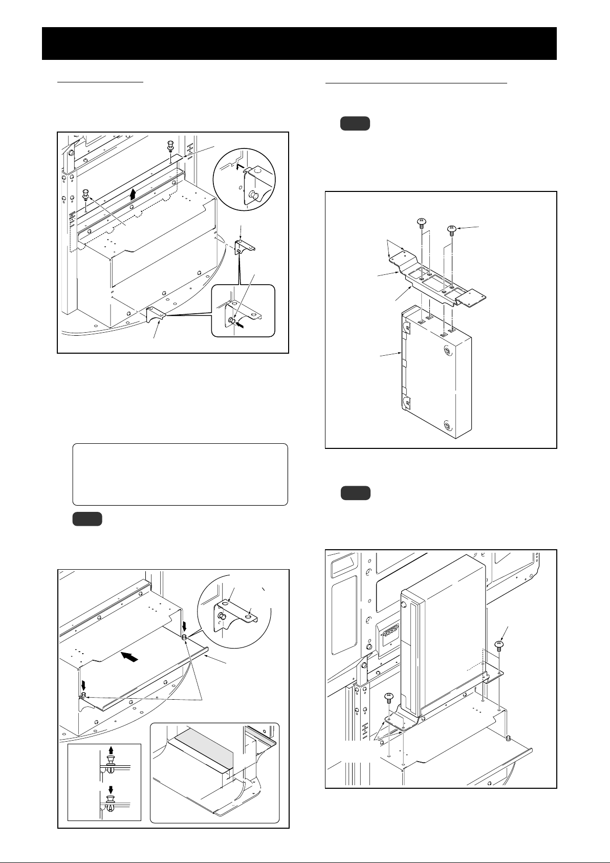
When using a shelf.
A shelf can be attached to the stand.
1 Remove the shelf cover and then attach the shelf supports
L and R to the stand.
Shelf cover
5
When attaching a media receiver upright.
1 Fit the MR holder over the sides of the media receiver and
fix into place using the four screws (M4 x 6 mm [1/4 inch]).
Note
The legs of the MR holder are on the side of the holder
with the indentations. Be sure to attach the holder in
the correct direction.
Do not attach the MR holder to anything other than a
media receiver.
Push rivet
Shelf support L
Push rivet
Push in
Shelf support R
2 Push the shelf panel in from behind and fix it in place with
the push rivet.
The shelf panel installation position be selected from
two levels: either the front or the back.
Set it accorrding to the device you have.
When changing its position, you can easily remove it
by pulling up the knob on the top of the push rivet.
Interior dimensions of the shelf opening: 420 mm [16-
17/32 inch] (effective width) <opening 436 [17-5/32] >
x 102 mm [4-1/32 inch] (height)
Depth of the shelf: 349 mm [13-3/4 inch]
Bearing capacity: up to 10 kg [20.1 lbs]
Note
Be careful when installing anything other than a media
receiver (particularly an AV amplifier etc.) on this shelf,
because it may block heat discharge etc. For details, see
the instruction manual for each device.
Hole for front
position use
Hole for back
position use
Rounded edges
MR holder
Indenations
Media
receiver
Screws (M4 x 6 mm
[1/4 inch])
2 Put the media receiver installed on the MR holder on the
shelf at the rear and fix the MR holder in place.
Note
Please make sure the media receiver is facing the proper
direction.
Do not install any device other than a media receiver in
this position.
Screws
(M4 x 6 mm
[1/4 inch])
En
Shelf panel
Push rivet
Rounded
Unlocked
position
Locked
position
Front side
Front
position
Back
position
edges
6

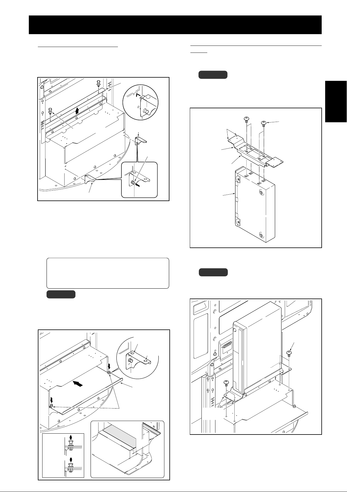
6
Installing base covers L, R, and rear.
Insert them along the base.
Base cover L
Base cover R
I
nstallation and assembly instructions
Base cover rear
English
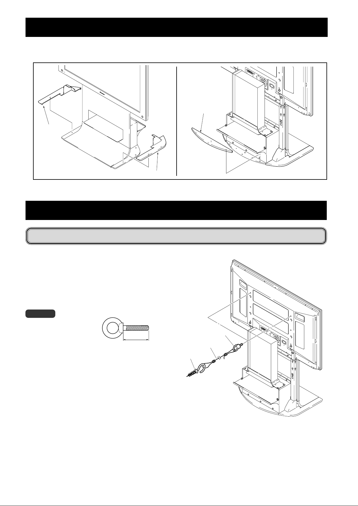
Preventing equipment from falling over
After installing the stand, be sure to take special care to ensure that the Plasma Display will not fall over.
1 Attaching falling prevention bolts to the Plasma
Display.
2 Using strong cords or chains to stabilize it appropri-
ately and firmly to a wall, pillar, or other sturdy
element.
Perform this work in the same way on the left and right sides.
Note
Use falling prevention bolts, ropes,
chains, and fittings that are available
on the market.
Recommended bolts:
Nominal diameter M8
Length 12 to 15 mm (1/2 to 5/8 inch)
12 to 15 mm
(1/2 to 5/8 inch)
1 Falling prevention bolts
2 Cord or chain
Fitting
7
En
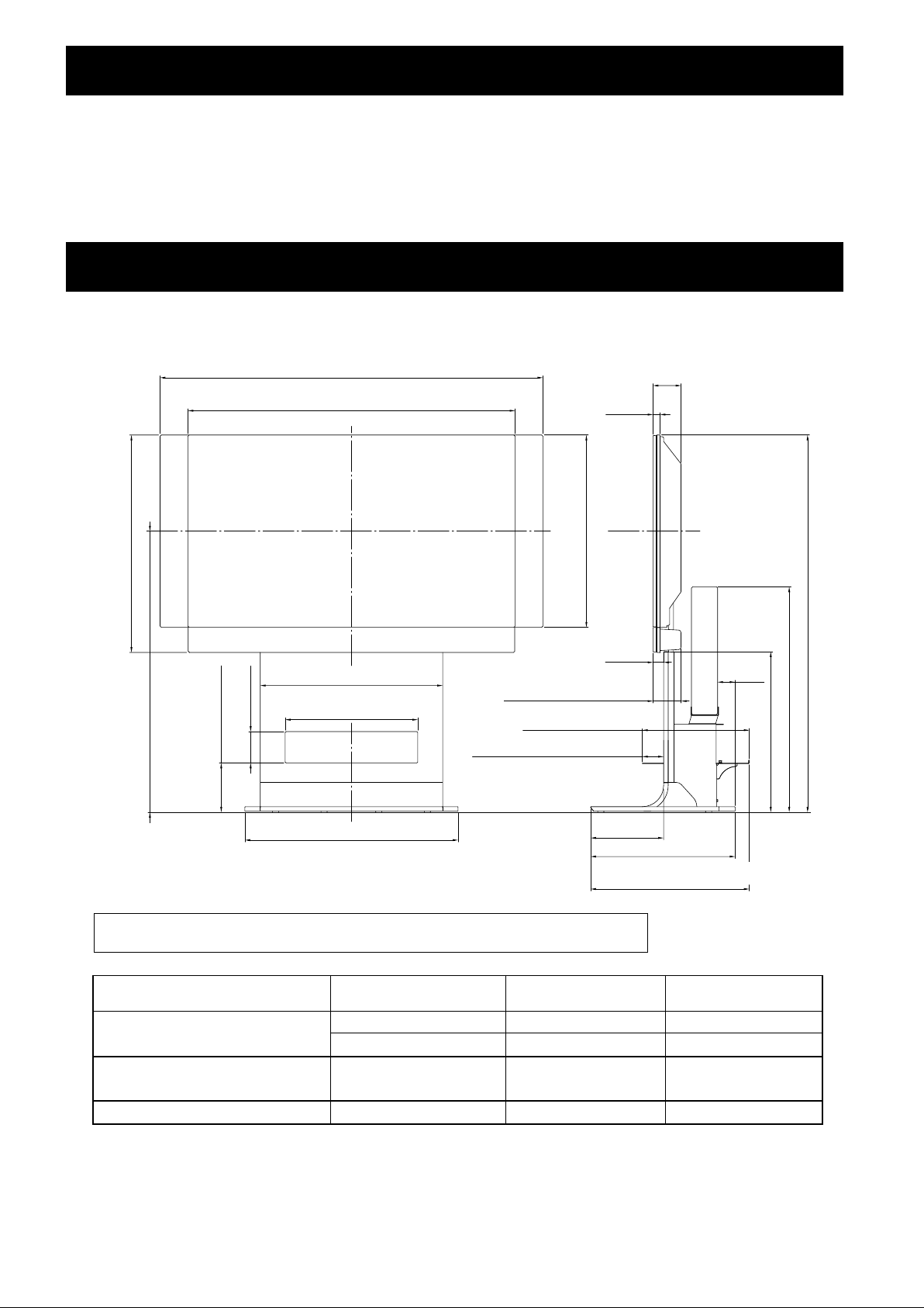
Specifications
External dimensions 701 (W) x 784 (H) x 567 (D) mm (27-19/32 (W) x 30-7/8 (H) x 22-5/16 (D) in.)
[When using high position support column and deep position shelf panel]
Weight 20.0 kg (44.1 lbs)
• The above specifications and exterior may be modified without prior notice to improve the product.
Dimensions diagram
Unit: mm (inch)
716 (28-7/32)
[43 inch display model with PDP-S39 speaker]
B
1407 (55-13/32) [50 inch display model with PDP-S38 speakers]*
1379 (54-5/16) [50 inch display model with PDP-S38 speakers]*
1259 (49-19/32) [43 inch display model with PDP-S37 speakers]*
1231 (48-15/32) [43 inch display model with PDP-S37 speakers]*
1224 (48-7/32) [50 inch display model]
1076 (42-3/8) [43 inch display model]
600 (23-5/8)
420 (16-17/32) [effective width]
<Opening 436 (17-5/32)>
Opening 102 (4-1/32)
1
2
1
2
25 (31/32) [Front panel deep position]
70 (2-3/4) [Shelf panel front position]
92 (3-5/8)
23 (29/32)
717 (28-1/4) [50 inch display model]
632 (24-29/32) [43 inch display model]
92 (3-5/8)
[When installing speakers at the
bottom of the plasma display]
349 (13-3/4) [Shelf surface]
35 (1-3/8)
A
58 (2-9/32)
742 (29-7/32)
528 (20-25/32)
En
162 (16-3/8) [Top of shelf panel]
240
701 (27-19/32)
*1 Air installation: Attached with a space of approximately 15 mm between the speakers and the display.
*2 Flush installation: Attached with the speakers in close contact with the display.
Plasma display
PDP-436XDE / PDP-436FDE / PDP-436HDG /
PDP-4360HD / PRO-930HD
PDP-506XDE / PDP-506FDE / PDP-506HDG /
PDP-5060HD / PRO-1130HD
One body type plasma display
Location of speakers
At sides of plasma display
Below plasma display
At sides of plasma display
–
Full height
(Dimensions A)
1,164 (45-13/16)
1,240 (48-13/16)
1,249 (49-3/16)
1,226 (48-9/32)
(7-7/16)
476 (18-3/4)
522 (20-9/16) [Shelf panel front position]
567 (22-5/16) [Front panel deep position]
Center of screen
(Dimensions B)
848 (33-3/8)
924 (36-3/8)
891 (35-3/32)
909 (35-25/32)
Published by Pioneer Corporation.
Copyright © 2005 Pioneer Corporation.
All rights reserved.
8

Nous vous remercions d’avoir procéder à l’achat d’un
produit Pioneer.
Veuillez lire attentivement ce Mode d’emploi pour savoir
comment opérer correctement et en toute sécurité votre
modèle.
Nous vous conseillons de conserver soigneusement de
Mode d’emploi dans un endroit sûr et à proximité afin de
pouvoir vous y référer le cas échéant.
AVIS IMPORTANT
Veuillez prendre note du numéro du modèle et du numéro de
série de cet équipement ci-dessous.
N° du modèle. PDK-FS06 N° de série.
Conservez ce numéro pour pouvoir l'utiliser ultérieurement.
AVERTISSEMENT
Pour éviter les risques d’incendie, ne placez aucune
flamme nue (telle qu’une bougie allumée) sur
l’appareil.
D3-4-2-1-7a_A_Fr
Attention
Ce produit est un support de base conçu exclusivement
pour les écrans d’affichage plasma (PDP-506XDE / PDP506FDE / PDP-506HDG / PDP-5060HD / PDP-436XDE /
PDP-436FDE / PDP-436HDG / PDP-4360HD / PRO-1130HD
/ PRO-930HD) fabriqués par la société PIONEER. Veuillez
noter que ce support de base n’a pas été conçu pour être
utilisé avec d’autres équipements. Pour de plus amples
informations, veuillez contacter le revendeur où vous avez
acheté votre écran d’affichage.
Veuillez ne pas installer le produit d’une manière autre que
celle spécifiée ou modifier ce dernier. En outre, veuillez ne
pas utiliser ce support pour un écran d’affichage plasma
autre que ceux pour lesquels il a été conçu et ni le modifier
ou l’utiliser à des fins autres que celles pour lesquelles il a
été conçu.
Une installation incorrecte est extrêmement dangereuse
car celle-ci peut provoquer le basculement du support ou un
autre accident.
English
Français
Installation
¶ Veuillez consulter votre revendeur si vous rencontrez
des difficultés lors de l’installation.
Pioneer n’assumera aucune responsabilité pour tout
dommage résultant d’une installation incorrecte, d’une
utilisation incorrecte, une modification de ce produit ou
encore de désastres naturels.
Table des matières
Attention .................................................................. 9
Liste des pièces et équipements inclus .............. 10
Instructions concernant l’installation et
l’assemblage du dispositif.................................... 11
Prévenir le basculement et la chute de
l’équipement.......................................................... 14
Spécificités............................................................. 15
Schéma indiquant les dimensions ...................... 15
ATTENTION
Ce symbole indique un danger ou une pratique dangereuse
risquant de compromettre la sécurité qui peut provoquer des
blessures ou des dégâts matériels.
Emplacement d’installation
•
Lorsque vous choisissez l’emplacement où sera placé le
support de base, veillez à sélectionner un endroit avec
une surface de base suffisamment solide pour supporter
le poids du support de base et de l’écran d’affichage
plasma (Le poids du produit est indiqué sur le Tableau
figurant à la page 15.)
•
S’assurer que l’emplacement d’installation est bien plane
et à niveau et prendre toutes les précautions utiles et
indispensables lors de l’installation du support afin de
veiller à ce que le poids soit bien uniformément réparti.
•
Selon le type de surface sur lequel sera placé le support
de base, les pieds pourront éventuellement laisser des
traces sur ladite surface et ceci devra être prendre en
considération lorsque l’on sélectionnera l’endroit où sera
installé le support de base.
• Ne pas installer le support à l’extérieur, à proximité d’une
source thermale ou sur la plage.
• Ne pas installer le support à un endroit où il pourrait être
soumis à des chocs ou à des vibrations.
Assemblage et installation
• Assembler le support conformément aux instructions
concernant l’assemblage et fixer solidement toutes
les vis aux endroits prévus à cet effet.
On a constaté des cas où des accidents imprévus
sont survenus (endommagement de l’équipement,
chute, etc.) après l’installation de l’écran d’affichage
parque le support n’avait pas été installé comme
indiqué dans les instructions.
• L’écran d’affichage doit toujours être installé au
moins par deux personnes afin de veiller à ce qu’il
soit installé en toute sécurité.
• Avant de procéder à l’installation, mettre l’écran ainsi
que les équipements périphériques hors tension en
coupant l’alimentation, puis retirer la prise du câble
d’alimentation électrique de la prise femelle murale.
Après installation
•
Ne jamais s’appuyer sur l’écran d’affichage plasma ou
appliquer une forte pression sur le support de base.
•
Il convient de prévenir les accidents causés par la chute
du produit en prenant des mesures fiables pour éviter le
basculement et la chute (Voir page 14).
•
Ne pas déplacer le support de base avec l’écran
d’affichage plasma, etc. fixé sur celui-ci.
9
Fr

Liste des pièces et équipements inclus
Veuillez vous assurer que toutes les pièces et tous les équipements indiqués ci-dessous sont bien contenus dans le carton
avant de commencer à monter le support de base.
• Veuillez prendre note qu’un tournevis de type Philips (non inclus avec les pièces) pour vis à empreinte cruciforme est
nécessaire pour assembler le support de base.
•
•
Support de base x 1 unité
Butée d’arrêt de la colonne de
support x 2 unités
•
Support d’étagère Droite x 1 unité
•
Support MR x 1
•
Support d’étagère Gauche x 1
unité
•
Couvercle de base Arrière x 1 unité
•
Couvercle de base Gauche x 1 unité
•
Couvercle de base Droite x 1 unité
•
Panneau étagère x 1 unité
•
Vis courtes à six pans (M8 x 35 mm : noir) x 4
•
Vis longues à six pans (M8 x 60 mm : argentée) x 2
•
Vis (M5 x 10 mm) x 10 unités
•
Vis (M4 x 6 mm) x 8 unités
10
•
Colonne de support x 2 unités
Fr
• Clé hexagonale x 1 unité
(Côté opposé 6 mm pour utilisation M8)
Mode d’emploi
(ce document) x 1 exemplaire
Floor stand
Support de base
Bodenständer
Supporto per display
Vloerstandaard
Soporte para colocar en el suelo
PDK-FS06
Operating instructions
Mode d’emploi
Bedienungsanleitung
Istruzioni per l’uso
Gebruiksaanwijzing
Manual de instrucciones

Extrémité avec le
couvercle en
plastique d’extrémité
pointée vers le haut.
Le côté avec
le symbole de
la flèche
’
est pointé
vers l’avant.
Instructions concernant l’installation et l’assemblage du dispositif
(Modèle d’écran de 43 pouces comme indiqué sur la figure)
1
Fixer les colonnes de support au support de base.
Tableau de l’emplacement de la colonne de support
et des pièces en fonction de chaque écran
PDP-436XDE
PDP-436FDE
PDP-436HDG
PDP-4360HD
PRO-930HD
Côté Dessous –
En bas En haut Au milieu
—
position
haute
Ecran à plasma
unique
position
basse
Ecran à plasma
Emplacement des hautsparleurs
Emplacement de la colonne
du support
Modalité d’assemblage
Butée d’arrêt de
la colonne du
support
Vis (M5 x 10 mm)
La fixation de
l’écran à plasma
se fait avec des
vis à six pans par
le dessus
Pièces utilisées
La fixation de
l’écran à plasma
se fait avec des
vis à six pans par
le dessous
Butée d’arrêt de
la colonne du
support
Vis (M5 x 10 mm)
utilisées
Pièces non
Vis à six pans
PDP-506XDE
PDP-506FDE
PDP-506HDG
PDP-5060HD
PRO-1130HD
Côté
En bas
AABC
inutile inutile
––22
court x 2 court x 2 court x 2 Long x 2
court x 2 court x 2 court x 2 court x 2
22––
22––
Long x 2 Long x 2 Long x 2 court x 2
A
Lors de l’installation du PDP-506XDE / PDP-506FDE /
PDP-506HDG / PRO-1130HD / PRO-930HD /
PDP-5060HD ou lors de l’installation des hautsparleurs sur les côtés du PDP-436XDE / PDP-436FDE
/ PDP-436HDG
Introduire les deux colonnes de support dans le support de
base et les mettre en place en les immobilisant avec les vis
(M5 x 10 mm). (8 emplacements)
Installer chaque colonne de support de telle sorte aue le côté
’
avec le symbole de la flèche verticale
soit vers l’avant et
l’extrémité avec le couvercle en plastique d’extrémité pointée
vers le haut.
Colonne de support
Vis (M5 x 10 mm)
Français
La procédure d’installation varie en fonction du type et de
la forme de l’écran à plasma qui doit être monté. Veuillez
procéder à l’installation en suivant soit la procédure
soit la procédure
Remarque
Veillez à bien ranger la butée d’arrêt de la colonne du support
non utilisée, les vis, les boulons, la clé hexagonale et le mode
d'emploi au même endroit.
A,
B, soit la procédure C.
B Lors de l’installation des haut-parleurs à la
base inférieure de l’écran d’affichage plasma
Placez les butées d’arrêt de la colonne du support dans les
fentes supérieures prévues à cet effet à l‘arrière du support et
fixez-les à l’aide des vis (M5 x 10 mm). (à deux emplacements
à gauche et à droite)
La même chose s’applique à la méthode d’installation de la
colonne A.
Butée d’arrêt de la
colonne de support
Vis (M5 x 10 mm)
11
Fr

Instructions concernant l’installation et l’assemblage du dispositif
3
C Lors de l’installation de l’écran à plasma unique
Placez les butées d’arrêt de la colonne du support dans les
fentes inférieures prévues à cet effet à l‘arrière du support et
fixez-les à l’aide des vis (M5 x 10 mm). (à deux emplacements
à gauche et à droite).
La même chose s’applique à la méthode d’installation de la
colonne A.
Butée d’arrêt de la
colonne de support
Vis (M5 x 10 mm)
Utilisez les vis courtes ou les vis longues à six pans
pour fixer l’écran à plasma à la colonne du support
(les vis doivent être vissées à quatre endroits).
Veuillez procéder à l’installation en commençant par visser les
vis du dessus.
Lors de l’installation du PDP-506XDE / PDP-506FDE /
PDP-506HDG / PDP-5060HD / PDP-436XDE / PDP436FDE / PDP-436HDG / PDP-4360HD / PRO-1130HD /
PRO-930HD
Utilisez les vis suivantes que vous fixerez à l’aide de la clé
hexagonale.
En haut........ Vis courtes à six pans (M8 x 35 mm : noir)
En bas ......... Vis courtes à six pans (M8 x 35 mm : noir)
Vis courtes à six pans
(M8 x 35 mm : noir)
2
Fixer l’écran d’affichage plasma sur la colonne de
support.
Placer les colonnes de support du support dans les fentes au
centre de la partie inférieure puis les insérer lentement et
directement dans les fentes. Veillez très soigneusement à ne
pas insérer les colonnes de support du support dans une
quelconque partie de l’écran d’affichage plasma autres que les
fentes prévues à cet effet. Veuillez noter que si vous faites cela
vous risquez d’endommager l’écran d’affichage ou les entrées
ou encore le support. Si l’écran d’affichage plasma est équipé
de poignées, il est généralement préférable de tenir l’écran
avec ses poignées lorsqu’on l’installe à la colonne de support.
Vis courtes à six pans
(M8 x 35 mm : noir)
Si vous souhaitez installer des haut-parleurs, veuillez le faire
au cours de cette étape de l’installation.
Veuillez vous référer au Mode d’emploi fourni avec les
haut-parleurs en ce qui concerne la procédure d’installation
des haut-parleurs.
Lors de l’installation de l’écran à plasma unique
Utilisez les vis suivantes que vous fixerez à l’aide de la clé
hexagonale.
En haut..... Vis longues à six pans (M8 x 60 mm : argentée)
En bas ...... Vis courtes à six pans (M8 x 35 mm : noir)
Vis longues à six pans
(M8 x 60 mm : argentée)
12
Aligner les supports de colonne
avec la partie inférieure de
l’écran d’affichage d’écran
comme indiqué sur le
diagramme ci-joint.
Lorsque l’on installe l’écran d’affichage, veuillez
procéder au moins avec une autre personne aux
Attention
Fr
opérations de montage du dispositif.
Veillez à ne pas coincer vos doigts entre l’écran
d’affichage et la colonne de support.
Vis courtes à six pans
(M8 x 35 mm : noir)
Instructions concernant l’installation et l’assemblage du dispositif
4
Lorsque l’on utilise une étagère.
Une étagère peut être montée sue le support de base.
1 Retirer le couvercle de l’étagère Retirer le couvercle de
l’étagère puis installer les supports de l’étagère gauche et
droit sur le support de base.
Couvercle de l’étagère
Support gauche
Rivet à poussoir
de l’étagère
5
Lorsque l’on installe transversalement un récepteur
média.
1 Adaptez le support MR sur les côtés du récepteur média
et fixez-le à l’aide des 4 vis (M4 x 6 mm).
Remarque
Les pieds du support MR sont sur le côté du support
avec les échancrures. Veillez à fixer le support dans le
bon sens.
N’installez le support MR qu’au récepteur média.
Bords arrondis
Vis (M4 x 6 mm)
Français
Rivet à
poussoir
Pousser
Support droit de l’étagère
à fond
2 Pousser le panneau de l’étagère à partir de l’arrière et le
mettre en place avec le rivet poussoir.
La position d’installation du panneau de l’étagère doit
être sélectionné pour l’un des deux niveaux soit le
niveau avant soit le niveau arrière.
L’installer en fonction du dispositif dont vous disposez.
Lorsque l’on change sa position, vous pouvez aisément
le retirer en enlevant le bouton sur la partie supérieure
du rivet poussoir.
Dimensions intérieures de l’ouverture intérieure de
l’étagère : 420 (efficace largeur) [Ouverturer 436] x 102
(hauteur) mm
Profondeur de l’étagère : 349 mm
Poids maxi (capacité de support) : jusqu’à 10 kg
Remarque
Soyez prudent lorsque vous installez autre chose que le
récepteur média (en particulier un amplificateur média,
etc.) sur l’étagère car cela pourrait réduire le dégagement
de la chaleur, etc. Pour de plus amples détails, veuillez vous
référer au Mode d’emploi pour chaque dispositif concerne.
Orifices pour
l’utilisation en
position avant
Orifices pour
l’utilisation en
position arrière
Support MR
Crans
Récepteur
média
2 Placez le récepteur média sur le support MR à l’arrière de
l’étagère et fixez le support MR.
Remarque
Veillez à ce que le récepteur média soit dans le bon sens.
Veuillez ne pas installer autre chose que le récepteur
média à cet endroit.
Vis (M4 x 6 mm)
Position
déverrouillée
Position
verrouillée
Côté avant
Panneau étagère
Rivet poussoir
Position
arrière
Position
avant
Bords
arrondis
13
Fr
Instructions concernant l’installation et l’assemblage du dispositif
6
Installation des couvercles de base gauche et droit.
Les introduire le long de la base.
Couvercle de
base arrière
Couvercle de
base gauche
Couvercle de base droit
Prévenir le basculement et la chute de l’équipement
Après avoir installé le support, veillez à prendre les précautions nécessaires pour que l’écran à plasma ne tombe pas.
1
Fixation des boulons empêchant la chute sur l’écran
à plasma.
2
Utilisation de câbles solides ou de chaînes pour
stabiliser solidement le dispositif sur un mur, un
pilier ou d’autres éléments stables.
Ces opérations doivent être effectuées de la même manière à
gauche et à droite.
Remarque
Utilisez des boulons, des cordons,
des chaînes ou d’autres dispositifs
de fixation en vente dans le
commerce.
Boulons recommandés : Diamètre nominal M8,
longueur de 12 à 15 mm.
12 à 15 mm
1
Vis de prévention de chutes
2 Câble ou chaîne
Attache
14
Fr

Spécificités
Dimensions ex térieures : 701 (largeur) x 784 (hauteur) x 567 (profondeur) mm
(Lorsqu’on utilise une colonne de support haute et une étagère profonde)
Poids : 20,0 kg
• Les caractéristiques techniques indiquées ci-dessus ainsi que les dimensions extérieures peuvent êtres modifiées sans avis
préalable en vue d’améliorer le produit.
Schéma indiquant les dimensions
Unités : mm
1407 (Ecran d’affichage de 50 pouces avec hauts-parleurs PDP-S38)*
1379 (Ecran d’affichage de 50 pouces avec hauts-parleurs PDP-S38)*
1259 (Ecran d’affichage de 43 pouces avec hauts-parleurs PDP-S37)*
1231 (Ecran d’affichage de 43 pouces avec hauts-parleurs PDP-S37)*
1224 (Ecran d'affichage 50 pouces)
1076 (Ecran d'affichage 43 pouces)
716
B
(Ecran d’affichage de 43 pouces avec hauts-parleurs PDP-S39)
Ouverture 102
600
420 (Efficace largeur)
[Ouverture 436]
1
2
1
2
23
717 (Ecran d'affichage 50 pouces)
632 (Ecran d'affichage 43 pouces)
35
92
(Lorsque l’on installe les haut-parleurs à
la base de l’écran d’affichage plasma)
349 (surface de l’étagère)
25 (Position en profondeur de l’étagère)
70 (Position frontale du panneau de l’étagère)
Français
92
A
58
742
528
162 (partie supérieure du
panneau frontal)
701
*1 Montage pivotant : fixées à une distance de 15 mm environ entre les haut-parleurs et l’écran.
*2 Montage à ras : fixées avec les haut-parleurs près de l’écran.
Écran à plasma Emplacement des haut-parleurs
PDP-436XDE / PDP-436FDE / PDP-436HDG /
PDP-4360HD / PRO-930HD
PDP-506XDE / PDP-506FDE / PDP-506HDG /
PDP-5060HD / PRO-1130HD
Un écran à plasma unique
Sur les côtés de l’écran à plasma
En-dessous de l’écran à plasma
Sur les côtés de l’écran à plasma
–
(dimensions A)
Publication de Pioneer Corporation.
© 2005 Pioneer Corporation.
Tous droits de reproduction et de traduction réservés.
240
476
522 (Position frontale du panneau de l’étagère)
567 (Position en profondeur de l’étagère)
Hauteur totale
Centre de l’écran
(dimensions B)
1.164
1.240
1.249
1.226
848
924
891
909
15
Fr

Wir danken Ihnen, dass Sie sich für den Kauf eines
Produkts der Firma Pioneer entschieden haben.
Bitte lesen die Bedienungsanleitung aufmerksam, um sich
über die sichere und richtige Bedienung Ihres Modells zu
informieren.
Wir empfehlen Ihnen, die Bedienungsanleitung
anschließend sicher aufzubewahren, um Sie später im
Bedarfsfalle zu Rate ziehen zu können.
Wichtiger Hinweis!
Bitte notieren Sie sich unten die Nummer des Modells und die
Serien-Nummer des Geräts.
Modell: PDK-FS06 Serien-Nummer:
Bewahren Sie diese Nummer für den künftigen Gebrauch.
WARNUNG
Keine Quellen offener Flammen (z.B. eine
brennende Kerze) auf dieses Gerät stellen.
D3-4-2-1-7a_A_Ge
Sicherheitshinweise
Dieses Produkt ist ein Bodenständer, der ausschließlich für
die Plasmadisplays der Firma Pioneer (PDP-506XDE / PDP506FDE / PDP-506HDG / PDP-5060HD / PDP-436XDE / PDP436FDE / PDP-436HDG / PDP-4360HD / PRO-1130HD / PRO930HD) bestimmt. Bitte beachten Sie, dass er nicht für den
Gebrauch mit einem anderen Gerät vorgesehen ist. Bitte
setzen Sie sich hinsichtlich weiterer Informationen mit der
Handelseinrichtung in Verbindung, in der Sie Ihr Display
gekauft haben.
Installieren Sie das Produkt nicht anders als angegeben und
nehmen Sie keine Änderungen am Produkt vor. Verwenden
Sie diesen Ständer nicht für ein anderes Plasmadisplay als
für das, für das es vorgesehen ist, verändern Sie ihn nicht
und verwenden Sie ihn nicht für andere Zwecke.
Eine falsche Installation ist sehr gefährlich, da sie zum
Umfallen des Displays oder einem anderen Unfall führen
kann.
Installation
¶ Bitte setzen Sie sich mit Ihrem Händler in Verbindung,
wenn Sie auf Schwierigkeiten bei der Installation
stoßen.
Die Firma Pioneer haftet nicht für Schäden, die auf falsche
Installation, auf inkorrekte Verwendung, auf vorgenommene
Veränderungen oder auf Naturkatastrophen zurückzuführen
sind.
Inhalt
Sicherheitshinweise.............................................. 16
Auflistung der zugehörigen Teile und des
sonstigen Zubehörs .............................................. 17
Installations– und Montageanweisungen .......... 18
Mittel zur Verhütung des Umstürzens................ 21
Technische Daten .................................................. 22
Abbildungen zu den Abmessungen .................... 22
Vorsicht!
Dieses Symbol kennzeichnet eine gefährliche oder riskante
Vorgehensweise, die zu eigenen Verletzungen, zu
Verletzungen anderer Personen oder zu Sachschäden führen
kann.
Installationsort
• Vergewissern Sie sich bei der Auswahl des Platzes, an
dem Sie den Bodenständer aufstellen wollen, dass dieser
Platz stabil genug ist, das Gewicht des Ständers und des
Plasmadisplays zu tragen (das jeweilige Produktgewicht
ist auf Seite 22 aufgelistet).
• Vergewissern Sie sich, dass der Installationsort eine
waagerechte, ebene und stabile Fläche ist und treffen Sie
beim Installieren die richtigen Vorkehrungen, dass Sie
sicher sein können, dass das Gewicht gleichmäßig
verteilt wird.
• Je nach der Beschaffenheit der Fläche, auf der der
Bodenständer aufgestellt wird, können die Beine
Eindrücke auf der betreffenden Oberfläche hinterlassen.
Das sollte bei der Auswahl des Platzes, an dem der
Bodenständer aufgestellt werden soll, berücksichtigt
werden.
• Installieren Sie den Ständer nicht im Freien, in der Nähe
einer heißen Quelle oder in Strandnähe.
• Installieren Sie den Ständer nicht an Orten, an denen er
Vibrationen oder Stößen ausgesetzt ist.
Montage und Installation
• Montieren Sie den Ständer gemäß den
Montageanweisungen und befestigen Sie alle
Schrauben sicher an den jeweils vorgesehenen
Positionen.
Es hat Fälle gegeben, in denen es nach der Installation des Displays zu unvorhergesehenen Unfällen wie
beispielsweise einem Bruch oder zum Umfallen kam,
weil der Ständer nicht wie vorgeschrieben installiert
wurde.
• Das Display muss stets von zwei oder mehr Personen
installiert werden, um zu sichern, dass es sicher
installiert wird.
• Schalten Sie das Display und periphere Geräte vor
der Installation aus und trennen Sie es bzw. sie durch
Herausziehen des Steckers aus der Steckdose vom
Netz.
16
Ge
Nach der Installation
• Stützen Sie sich auf keinen Fall auf das Plasmadisplay
und üben Sie niemals starken Druck auf den
Bodenständer aus.
• Beugen Sie Unfällen durch das Umfallen des Produkts
vor, indem Sie zuverlässige Maßnahmen treffen, die es
vor dem Umfallen bewahren (siehe Seite 21).
• Bewegen Sie den Bodenständer nicht mit den bereits
oder noch montierten Plasmadisplay.

Auflistung der zugehörigen Teile und des sonstigen Zubehörs
Vergewissern Sie sich, ehe Sie mit der Installation ihres Bodenständers beginnen, dass alle unten dargestellten Teile und das
sonstige Zubehör vorhanden sind.
• Bitte beachten Sie, dass für die Montage ein Kreuzschlitzschraubenzieher (nicht enthalten) erforderlich ist.
• Bodenständer: 1
•
Grundplattenabdeckung L: 1
•
Grundplattenabdeckung Rückseite: 1
• Stützsäulensperre: 2
• Auflagestütze R: 1
•
Kurze Innensechskantschrauben (M8 x 35 mm, schwarz): 4
•
Lange Innensechskantschrauben (M8 x 60 mm, silberfarben) : 2
•
MR-Halterung: 1
•
Auflagestütze L: 1
Deutsch
•
Auflageplatte: 1
•
Stützsäulen: 2
•
Grundplattenabdeckung R: 1
•
Schrauben (M5 x 10 mm): 10
•
Schrauben (M4 x 6 mm): 8
Sechskant-Stiftschlüssel: 1
(gegenüberliegende Seite 6 mm für
M8-Schrauben)
Bedienungsanleitung
(dieses Dokument): 1
Floor stand
Support de base
Bodenständer
Supporto per display
Vloerstandaard
Soporte para colocar en el suelo
PDK-FS06
Operating instructions
Mode d’emploi
Bedienungsanleitung
Istruzioni per l’uso
Gebruiksaanwijzing
Manual de instrucciones
17
Ge

Installations– und Montageanweisungen (In der Abbildung ist ein 43-Zoll-Modell dargestellt)
1
Montage der Stützsäulen am Bodenständer.
Tabelle der Stützsäulenposition und der Teile für
jedes Plasmadisplay
PDP-506XDE
Plasmadisplay
Anordnung der Lautsprecher
Stützsäulenposition
Verfahrensweise der
Befestigung der
Stützsäulen
Stützsäulensperre
Schraube
(M5 x 10 mm)
Obere Innensechskantschrauben zur
Befestigung des
Plasmadisplays
Verwendete Teile
Untere Innensechskantschrauben zur
Befestigung des
Plasmadisplays
Stützsäulensperre
Schraube
(M5 x 10 mm)
Teile
Innensechskant-
Nicht verwendete
schrauben
PDP-506FDE
PDP-506HDG
PDP-5060HD
PRO-1130HD
seitlich
niedrig
AABC
nicht
erforderlich
––22
kurz x 2 kurz x 2 kurz x 2 lang x 2
kurz x 2 kurz x 2 kurz x 2 kurz x 2
22––
22––
lang x 2 lang x 2 lang x 2 kurz x 2
Die Art und Weise der Montage ändert sich je nach Typ
und Modell des zu montierenden Plasmadisplays. Führen
Sie die Montage unter Anwendung der jeweiligen
Verfahrensweise
A, B oder C aus.
PDP-436XDE
PDP-436FDE
PDP-436HDG
PDP-4360HD
PRO-930HD
seitlich unten –
niedrig hoch Mittelposition
nicht
erforderlich
Position
—
hohe
Einkörper-
Plasmadisplay
niedrige
Position
A Installation der Typen PDP-506XDE /
PDP-506FDE / PDP-506HDG /PRO-1130HD /
PRO-930HD und PDP-5060HD oder seitliche
Installation der Lautsprecher bei den Typen
PDP-436XDE / PDP-436FDE und PDP-436HDG
Führen Sie die Stützsäulen in den Bodenständer ein und
schrauben Sie die betreffenden Stützsäulen wie vorgesehen
mit Schrauben (M5 x 10 mm) fest (8 Positionen).
Montieren Sie jede Stützsäule so, dass die Seite mit dem
Symbol ’ nach vorn zeigt und das Ende mit der KunststoffAbdeckklappe (wie angezeigt) nach oben gerichtet ist.
Ende der
Abdeckklappe ist
nach oben gerichtet.
Seite mit
dem Symbol
’
zeigt nach
vorn.
Schraube
(M5 x 10 mm)
Colonne de support
Hinweis
Bewahren Sie die nicht verwendeten Stützsäulenstopper und
Schrauben sowie den Innensechskant-Stiftschlüssel und die
vorliegende Betriebsanleitung zusammen und sicher auf.
B Installation der Lautsprecher unter dem
Plasmadisplay
Bringen Sie die Stützsäulenstopper an den auf der Rückseite
des Ständers in der hohen Position befindlichen Einkerbungen
an und befestigen Sie sie in dieser Position mit den dafür
vorgesehenen Schrauben (M5 x 10 mm) (2 Positionen links
und rechts). Dasselbe gilt auch für die Verfahrensweise A zur
Montage der Stützsäulen.
Stüzsäulensperre
Schraube (M5 x 10 mm)
18
Ge

C Installation des Einkörper-Plasmadisplays
Bringen Sie die Stützsäulenstopper an den auf der Rückseite
des Ständers in der niedrigen Position befindlichen
Einkerbungen an und befestigen Sie sie in dieser Position mit
den dafür vorgesehenen Schrauben (M5 x 10 mm) (2
Positionen links und rechts). Dasselbe gilt auch für die
Verfahrensweise A zur Montage der Stützsäulen.
Stüzsäulensperre
Schraube (M5 x 10 mm)
Installations– und Montageanweisungen
3
Verwenden Sie die kurzen oder die langen
Innensechskantschrauben zur Montage des
Plasmadisplays an den Stützsäulen (4 Positionen).
Beginnen Sie mit den oberen Schrauben.
Installation der Typen PDP-506XDE / PDP-506FDE /
PDP-506HDG / PDP-5060HD / PDP-436XDE /
PDP-436FDE / PDP-436HDG /PDP-4360HD /
PRO-1130HD und PRO-930HD
Verwenden Sie die folgenden Schrauben zur Montage mit
dem Innensechskant-Stiftschlüssel:
Oben: Kurze Innensechskantschrauben (M8 x 35 mm,
schwarz)
Unten: Kurze Innensechskantschrauben (M8 x 35 mm,
schwarz)
Kurze Innensechskantschrauben
(M8 x 35 mm, schwarz)
Deutsch
2
Befestigen Sie das Plasmadisplay an der Stützsäule.
Passen Sie die Stützsäulen des Ständers den Öffnungen in der
Mitte unten am Plasmadisplay an und führen Sie sie dann
langsam direkt in die Öffnungen ein. Achten Sie bitte unbedingt
darauf, dass sie die Stützsäulen des Ständers nicht in
irgendeinen anderen Teil des Ständers einführen als in die dafür
vorgesehenen Öffnungen. Wenn Sie dies nicht beachten,
besteht die Gefahr, dass Sie das Bedienfels des Plasmadisplays
beschädigen oder seine Anschlussbuchsen oder dass sich der
Ständer verzieht. Wenn das Plasmadisplay mit Griffen versehen
ist, ist es gewöhnlich das Beste, das Display an den Griffen zu
halten, wenn es an der Stützsäule befestigt wird.
Kurze Innensechskantschrauben
(M8 x 35 mm, schwarz)
Montieren Sie die Lautsprecher in diesem Stadium der
Installation.
Zur Verfahrensweise der Installation der Lautsprecher
siehe die mit Ihren Lautsprechern mitgelieferten
Installationsanweisungen.
Installation des Einkörper-Plasmadisplays
Verwenden Sie die folgenden Schrauben zur Montage mit
dem Innensechskant-Stiftschlüssel:
Oben: Lange Innensechskantschrauben (M8 x 60 mm:
silberfarben)
Unten: Kurze Innensechskantschrauben (M8 x 35 mm:
schwarz)
Lange Innensechskantschrauben
(M8 x 60 mm: silberfarben)
Vorsicht!
Bringen Sie die Stützsäulen in
Übereinstimmung mit dem
unteren Teil des Plasamdisplays,
wie es in der zugehörigen
Abbildung dargestellt ist.
Arbeiten Sie bei der Befestigung des Displays
unbedingt mit mindesten einer anderen Person
zusammen.
Achten Sie sorgsam darauf, dass ihre Finger nicht
zwischen das Plasmadisplay und die Stützsäule
gelangen.
Kurze Innensechskantschrauben
(M8 x 35 mm: schwarz)
19
Ge

Installations– und Montageanweisungen
4
Verwendung einer Auflageplatte.
An den Bodenständer kann eine Auflageplatte montiert werden.
1 Entfernen Sie die Abdeckung der Auflageplatte und
montieren Sie dann die dafür vorgesehenen Stützen L
und R am Bodenständer.
Abdeckung für Auflageplatte
Stütze L für
Druckniet
Auflageplatte
Druckniet
5
Anbringen eines Medien-Receives in aufrechter
Position.
1 Passen Sie die MR-Halterung über die Seiten des
Medienreceivers ein und befestigen Sie sie mit den vier
dafür vorgesehenen Schrauben (M4 x 6 mm) in ihrer
Position.
Hinweis
Die Schenkel der MR-Halterung haben an ihrem unteren
Ende Einschnitte. Achten Sie darauf, die Halterung in der
richtigen Richtung anzubringen.
Verwenden Sie die MR-Halterung für nichts anderes als
für den Medien-receiver.
Abgerundete Ecken
MR-Halterung
Schrauben
(M4 x 6 mm)
Eindrücken
Stütze R für Auflageplatte
2 Drücken Sie die Auflageplatte von hinten ein und
befestigen Sie die Platte mit dem Druckniet.
Die Installationsposition der Auflageplatte kann von
zwei Ebenen aus gewählt werden: entweder von der
Vorderseite oder von der Rückseite. Stellen Sie die
Position je nach dem Gerät ein, das Sie haben.
Wenn Sie die Position der Platte ändern wollen,
können Sie sie leicht entfernen, indem Sie den Knopf
auf dem Druckniet nach oben ziehen.
Innenabmessungen der Öffnung der Auflageplatte: 420
(Wirksam weite) [Öffnung 436] x 102 (Höhe) mm
Tiefe der Auflageplatte: 349 mm
Zulässige Belastung: maximal 10 kg
Hinweis
Seien Sie bitte vorsichtig, wenn Sie auf dieser
Auflageplatte etwas anderes unterbringen als einen
Medien-Receiver (insbesondere einen AV-Verstärker usw.),
da ein solches Gerät unter anderem die Abführung der
entstehenden Wärme blockieren könnte. Zu Einzelheiten
siehe die Bedienungsanleitung für das jeweilige Gerät.
Öffnung für die Verwendung
in Vorderseiten-Position
Öffnung für die
Verwendung in
Rückseiten-Position
Einkerbungen
MedienReceiver
2 Stellen Sie den an der MR-Halterung auf der Gestellplatte
auf der Rückseite montierten Medien-receiver.
Hinweis
Bitte vergewissern Sie sich, dass der Medien-receiver die
richtige Ausrichtung aufweist.
Installieren Sie kein anderes Gerät als einen Medien-
receiver in dieser Position.
Schrauben
(M4 x 6 mm)
20
Ge
Unbefestigte
Position
Unbefestigte
Position
Vorderseite
Druckniet
VorderseitenPosition
Auflageplatte
ückseiten-
R
Position
Abgerundete
Ecken

6
Installieren der Grundplattenabdeckungen L, R und Rückseite.
Schieben Sie die Abdeckungen entlang der Grundplatte ein.
Installations– und Montageanweisungen
Grundplattenabdeckung
Rückseite
Grundplattenabdeckung L
Grundplattenabdeckung R
Mittel zur Verhütung des Umstürzens
Ergreifen Sie nach der Installation des Ständers mit Plasmadisplay spezielle Maßnahmen, die sichern,
dass die Einheit nicht umstürzt.
1
Befestigen von Sicherungsschrauben zur Verhütung
des Umfallens am Plasmadisplay.
2
Verwendung starker Schnuren oder Ketten zur
angemessenen und sicheren Stabilsierung der
Einheit an einer Wand, einer Säule oder einem
anderen stabilen Bauelement.
Führen Sie diese Arbeiten in derselben Art und Weise auf der
linken und der rechten Seite aus.
Hinweis
Verwenden Sie handelsübliche
Sicherungsschrauben, Schnuren/
Seile, Ketten und Schraubhaken.
Empfohlene Schrauben:
Nenndurchmesser M8, Länge 12 – 15 mm
12–15 mm
1
Sicherungsschrauben
2 Seil oder Kette
Schraubhaken
Deutsch
21
Ge

Technische Daten
Außenabmessungen: 701 (B) x 784 (H) x 567 (T) mm
(Bei Stützsäulen in hoher Position und Gestellplatte in tiefliegender Position.)
Gewicht: 20,0 kg
•
Die oben aufgeführten technischen Daten und das Äußere können aus Gründen der Verbesserung des Produkts ohne vorherige
Ankündigung verändert werden.
Abbildungen zu den Abmessungen
Einheit: mm
1
2
1
2
92
23
716
1407 (50-Zoll-Display-modell mit PDP-S38-Lautsprechern)*
1379 (50-Zoll-Display-modell mit PDP-S38-Lautsprechern)*
1259 (43-Zoll-Display-modell mit PDP-S37-Lautsprechern)*
1231 (43-Zoll-Display-modell mit PDP-S37-Lautsprechern)*
1224 (50-Zoll-Display-Modell)
1076 (43-Zoll-Display-Modell)
717 (50-Zoll-Display-Modell)
632 (43-Zoll-Display-Modell)
(43-Zoll-Display-modell mit PDP-S39-Lautsprechern)
B
Öffnung 102
162 (Oberseite der Auflageplatte)
*1 Versetzte Installation: Montage mit einem Abstand von etwa 15 mm zwischen den Lautsprechern und dem Display.
*2 Bündige Installation: Montage in engem Kontakt mit dem Display.
600
420 (Wirksam weite)
<Öffnung 436>
701
Plasmadisplay Installation der Lautsprecher
PDP-436XDE / PDP-436FDE / PDP-436HDG /
PDP-4360HD / PRO-930HD
PDP-506XDE / PDP-506FDE / PDP-506HDG /
PDP-5060HD / PRO-1130HD
Einkörper-Plasmadisplay
An den Seiten des Plasmadisplays
Unter dem Plasmadisplay
An den Seiten des Plasmadisplays
–
92
(Bei Installation der Lautsprecher
unterhalb des Plasmadisplays)
349 (Oberfläche der Auflageplatte)
25 (Hintere Position der Auflageplatte)
70 (Vordere Position der Auflageplatte)
(Abmessungen A)
35
240
522 (Vordere Position der Auflageplatte)
567 (Hintere Position der Auflageplatte)
476
Gesamthöhe
1.164
1.240
1.249
1.226
A
58
742
528
Bildschirmmitte
(Abmessungen B)
848
924
891
909
22
Ge
Ver öffentlicht von Pioneer Corporation.
Urheberrechtlich geschützt © 2005 Pioneer
Corporation. Alle Rechte vorbehalten.

La ringraziamo per avere acquistato un prodotto Pioneer.
Vi preghiamo di leggere attentamente le Istruzioni per l’uso
per imparare il modo sicuro e corretto di operare sul vostro
modello. Vi consigliamo di tenere le Istruzioni per l’uso a
portata di mano per farvi riferimento futuro.
AVVISO IMPORTANTE
Registrate il numero di modello e di serie
dell’apparecchio qui sotto.
Model N. PDK-FS06 Serial No.
Conservate questo numero per usarlo in futuro.
ATTENZIONE
Per evitare il pericolo di incendi, non posizionare
sull’apparecchio dispositivi con fiamme vive (ad
esempio una candela accesa, o simili).
D3-4-2-1-7a_A_It
Installazione
¶ Se incontrate qualsiasi difficoltà durante l’installazione,
rivolgetevi al vostro rivenditore.
Pioneer non è responsabile per alcun danno causato da
un’installazione impropria, o dall’uso improprio, nonché da
modifiche o catastrofi naturali.
Indice
Precauzioni ............................................................ 23
Elenco dei pezzi e delle attrezzature contenuti
nella confezione .................................................... 24
Istruzioni per l’installazione e il montaggio ....... 25
Prendere precauzioni contro la caduta
dell’apparecchio .................................................... 28
Specifiche............................................................... 29
Diagramma delle Dimensioni............................... 29
ATTENZIONE
Questo simbolo si riferisce a una pratica pericolosa o insicura
che potrebbe causare incidenti alla persona o alle cose.
Precauzioni
Questo prodotto è un supporto per display progettato
esclusivamente per i display a plasma (PDP-506XDE / PDP506FDE / PDP-506HDG / PDP-5060HD / PDP-436XDE /
PDP-436FDE / PDP-436HDG / PDP-4360HD / PRO-1130HD
/ PRO-930HD) di Pioneer. Prendete nota che non è stato
progettato per alcun altro apparecchio. Per ulteriori
informazioni rivolgetevi al negozio dove lo avete acquistato.
Non installate o modificate il prodotto in alcun altro modo
diverso da quello indicato. Non usate questo supporto per
display a plasma progettati da altri e non modificatelo o
usatelo per altri scopi.
Un’installazione impropria è molto pericolosa perché
potrebbe cadervi addosso o causare altri incidenti.
Posizionamento dell’installazione
• Assicuratevi di scegliere una posizione con una superficie
abbastanza robusta da sostenere il peso del supporto e
del display a plasma, dove collocarlo. (Il peso del prodotto
è elencato a p.29.)
• Assicuratevi che la posizione dell’installazione sia su una
superficie a livello, piatta e stabile, e prendete le
precauzioni necessarie mentre lo installate per assicurarvi
che il peso venga distribuito equamente.
• Secondo il tipo di superficie su cui collocate il supporto, le
gambe possono lasciare impronte e sarebbe bene
tenerne conto nella scelta della posizione in cui collocarlo.
• Non installatelo all’esterno, su una fonte di calore o vicino
ad una spiaggia.
• Non installate il supporto dove potrebbe essere soggetto
a vibrazioni o colpi.
Assemblaggio e installazione
• Assemblate il supporto conformemente alle istruzioni
per l’assemblaggio e la sicurezza, fissate tutte le viti
nelle apposite sedi.
Esistono casi dove incidenti imprevisti, come la
rottura dell’attrezzatura o la caduta possono
verificarsi dopo l’installazione del display a plasma,
perché il supporto non era stato installato
correttamente.
• Il display deve sempre essere installato da due o più
persone per assicurarsi di installarlo correttamente.
• Prima dell’installazione spegnete il display e i
dispositivi periferici, quindi staccate il cavo con la
spina di corrente dalla presa.
Dopo l’installazione
• Non appoggiatevi mai al display a plasma e non applicate
mai una forte pressione sul supporto.
• Evitate incidenti prendendo precise precauzioni contro la
caduta dell’apparecchio (vedi a pagina 28).
• Non spostate il supporto con il display a plasma, ecc.,
ancora inserito.
Deutsch
Italiano
23
It

Elenco dei pezzi e delle attrezzature contenuti nella confezione
Verificate di avere ricevuto tutti i pezzi e le attrezzature elencate qui sotto prima di procedere al montaggio del supporto.
• Vi preghiamo di notare che per il montaggio è necessario un cacciavite Philips (che non è incluso).
•
• Supporto x 1
•
Copertura a L della base x 1
•
Copertura posteriore della base x 1
•
Ferma colonna di sostegno x 2
•
Supporto mensola R x 1
•
Bulloni esagonali corti (M8 x 35 mm: neri) x 4
Supporto MR x 1
•
Supporto mensola L x 1
•
Pannello mensola x 1
•
Colonna di sostegno x 2
•
Copertura della base R x 1
•
Bulloni esagonali lunghi (M8 x 60 mm: argento) x 2
•
Viti (M5 x 10 mm) x 10
•
Viti (M4 x 6 mm) x 10
Brugola esagonale x 1
(Parte opposta di 6 mm per uso M8)
Istruzioni per l’uso
(questo documento) x 1
Floor stand
Support de base
Bodenständer
Supporto per display
Vloerstandaard
Soporte para colocar en el suelo
PDK-FS06
24
Operating instructions
Mode d’emploi
Bedienungsanleitung
Istruzioni per l’uso
Gebruiksaanwijzing
Manual de instrucciones
It

Istruzioni per l’installazione e il montaggio
1
Applicare le colonne di sostegno allo stand.
Tabella della posizione della colonna di
sostegno e dei pezzi in dotazione con ogni
display a plasma
PDP-436XDE
PDP-436FDE
PDP-436HDG
PDP-4360HD
PRO-930HD
Di lato Sotto –
Basso Alto Medio
Non
necessario
—
Posizione alta
Display a
plasma
compatto
(a corpo unico)
Posizione
bassa
Display a plasma
Ubicazione degli altoparlanti
Posizione della colonna di
sostegno
Metodo di applicazione
Ferma colonna di
sostegno
Viti (M5 x 10mm)
Per fissare il
display a plasma
usate la parte alta
dei bulloni
esagonali
Pezzi utilizzati
Per fissare il
display a plasma
utilizzate la parte
inferiore dei
bulloni esagonali
Ferma colonna di
sostegno
Viti (M5 x 10mm)
utilizzati
Pezzi non
Bulloni esagonali
PDP-506XDE
PDP-506FDE
PDP-506HDG
PDP-5060HD
PRO-1130HD
Di lato
Basso
AABC
Non
necessario
––22
Corti x 2 Corti x 2 Corti x 2 Lunghi x 2
Corti x 2 Corti x 2 Corti x 2 Corti x 2
22––
22––
Lunghi x 2 Lunghi x 2 Lunghi x 2 Corti x 2
La procedura di applicazione varia secondo il tipo e la
forma del display a plasma che deve essere inserito.
Eseguite questa applicazione utilizzando sia la procedura
A, la B, o la C.
Nota
Assicuratevi di conservare insieme con cura i ferma colonne di
sostegno non utilizzati, le viti, i bulloni, la brugola esagonale e
le istruzioni per l’uso.
B Quando installate gli altoparlanti nella parte
inferiore del display a plasma
Applicate i fermi della colonna di sostegno nelle scanalature
poste in alto sulla parte posteriore del supporto e fissateli in
posizione con le viti (M5 x 10mm). (Due posizioni sulla destra
e sulla sinistra). La stessa cosa va fatta per il metodo A di
applicazione della colonna di sostegno.
C Se installate il display a plasma compatto a
corpo unico
Applicate i fermi della colonna di sostegno nelle scanalature
poste in basso sulla parte posteriore del supporto e fissateli in
posizione con le viti (M5 x 10mm). (Due posizioni sulla destra
e sulla sinistra). La stessa cosa va fatta per il metodo A di
applicazione della colonna di sostegno.
(la figura illustra il display da 43 pollici)
Ferma colonna di
sostegno
Vite (M5 x 10mm)
Italiano
A Se installate il PDP-506XDE, PDP-506FDE, PDP-
506HDG, PRO-1130HD, PRO-930HD, PDP5060HD o se installate gli altoparlanti ai lati del
PDP-436XDE, PDP-436FDE, PDP-436HDG
Inserite le colonne di supporto nel supporto e fissatele nella
posizione corretta con le viti (M5 x 10 mm) (8 posizioni).
Installate ogni colonna di sostegno in modo che la parte con
il simbolo
il coperchio di plastica (punteggiato) al contrario.
Alla fine i punti del
coperchio finale
saranno al contrario.
La parte con il
simbolo
anteriore.
Vite
(M5 x 10 mm)
’
si trovi nella parte anteriore e la parte finale con
Colonna di sostegno
’
è
Ferma colonna di
sostegno
Vite (M5 x 10mm)
25
It

Istruzioni per l’installazione e il montaggio
2
Fissate il display a plasma alla colonna di sostegno.
Incastrate le colonne di sostegno nelle scanalature poste al
centro della superficie inferiore del display a plasma, quindi
inserirtele lentamente nelle stesse. Fate molta attenzione ad
inserirle esattamente nelle scanalature del display a plasma e
solo in quel punto. Agire in un altro modo può danneggiare il
pannello del display a plasma, le sue aperture o provocare una
deformazione del supporto.
La cosa migliore è tenere il display a plasma per i manici
durante il montaggio sulla colonna di sostegno, qualora ne sia
fornito.
3
Utilizzate i bulloni esagonali lunghi per fissare il
display a plasma alla colonna di sostegno (4
posizioni).
Iniziate l’installazione dai bulloni in alto.
Se installate il PDP-506XDE / PDP-506FDE / PDP506HDG / PDP-5060HD / PDP-436XDE / PDP-436FDE /
PDP-436HDG / PDP-4360HD / PRO-1130HD / PRO-930HD
Utilizzate i bulloni seguenti per fissarlo con la brugola
esagonale.
Parte superiore ..... Bulloni esagonali corti (M8 x 35mm: neri)
Parte inferiore ....... Bulloni esagonali corti (M8 x 35mm: neri)
Bulloni esagonali corti
(M8 x 35mm: neri)
Attenzione
Allineate le colonne di
sostegno con la parte inferiore
del display a plasma, come
indicato nello schema allegato.
Assicuratevi di lavorare almeno con un’altra
persona al montaggio del display.
Prestate attenzione a non permettere che le vostre
dita siano schiacciate tra il display e la colonna.
Bulloni esagonali corti
(M8 x 35mm: neri)
Se state applicando gli altoparlanti, fatelo a questo punto.
Vedi le istruzioni per l’installazione fornite insieme agli
altoparlanti per le istruzioni su come installarli.
Se installate il display a plasma compatto a corpo
unico
Utilizzate i bulloni seguenti per fissarlo con la brugola
esagonale.
Parte superiore ..... Bulloni esagonali lunghi (M8 x 60mm:
argento)
Parte inferiore ....... Bulloni esagonali corti (M8 x 35mm: neri)
Bulloni esagonali lunghi
(M8 x 60mm: argento)
26
Bulloni esagonali corti
(M8 x 35mm: neri)
It

4
Quando usare una mensola.
Sul supporto è possibile installare una mensola.
1 Togliete la copertura della mensola e applicatela ai supporti
di mensola a L e R sul supporto.
Copertura della mensola
Supporto della
Ribattino
di spinta
Supporto della mensola a R
mensola a L
Ribattino
di spinta
Eindrücken
2 Spingete il pannello della mensola all’interno dalla parte
posteriore e fissatelo con il ribattino di spinta.
La posizione di installazione del pannello della mensola
può essere scelta tra due livelli: sia l’anteriore sia il
posteriore, Decidete in base all’apparecchio in vostro
possesso.
Se cambiate la sua posizione, potete facilmente
rimuoverlo tirando pomello sopra il ribattino di spinta.
Le dimensioni interne dell’apertura della mensola: 420
(effettivo larghezza) [apertura 436] x 102 (altezza) mm.
Profondità della mensola: 349 mm
Capacità di sostegno: fino a 10 kg.
Nota
Prestate attenzione a non installare null’altro che un
ricevitore media (in particolare un amplificatore AV, ecc.) su
questa mensola, poiché si potrebbe bloccare lo scarico di
calore, ecc. Per i dettagli, vedi il manuale di istruzioni per
ciascun apparecchio.
Foro per uso
anteriore
Foro per uso
posteriore
Istruzioni per l’installazione e il montaggio
5
Istruzioni per il montaggio di un ricevitore media
verticale.
1 Incastrate la staffa di supporto MR sui lati del ricevitore
media e fissatela nella giusta posizione usando le quattro
viti (M4 x 6mm).
Nota
Le gambe della staffa di supporto si trovano sui lati della
staffa con l’apposita rientranza. Assicuratevi di applicare
la staffa nella corretta direzione.
Applicate la staffa di supporto solo a un ricevitore
media.
Bordi arrotondati
Supporto MR
Scanalature
Ricevitore
media
2 Installate il ricevitore media sul supporto MR nella parte
posteriore della mensola e fissate il supporto MR nella
giusta posizione.
Nota
Assicuratevi che il ricevitore media si trovi nella giusta
direzione.
Installate solo ricevitore media, e non altri apparecchi, in
questa posizione.
Vite (M4 x 6 mm)
Italiano
Posizione
sbloccata
Posizione
bloccata
Parte
anteriore
Pannello della
mensola
Ribattino di spinta
teriore
s
o
P
Anteriore
Vite (M4 x 6 mm)
Bordi arrotondati
27
It

Istruzioni per l’installazione e il montaggio
6
Installare le coperture della base a L, R, e la posteriore.
Inserirle lungo la base.
Copertura a L
della base
Copertura a R della base
Copertura posteriore
della base
Prendere precauzioni contro la caduta dell’apparecchio
Dopo avere installato il supporto, assicuratevi di usare particolare attenzione affinché il Display a
Plasma non possa cadere.
1
Avvitate i bulloni di sicurezza al Display a Plasma
per prevenire le cadute.
2
Usate corde o catene robuste per stabilizzarlo con
sicurezza e saldamente al muro, a un pilastro o a
qualche altro solido elemento.
Eseguite questo lavoro nello stesso modo sul lato sinistro e su
quello destro.
Nota
Usate bulloni anticaduta, cordoni,
catene o raccordi disponibili sul
mercato.
Bulloni consigliati: diametro nominale
M8, lunghezza da 12 a 15 mm
da 12 a 15 mm
1
Bulloni anticaduta
2 Cordone o catena
Raccordo
28
It

Specifiche
Dimensioni esterne 701mm (L) x 784mm (A) x 567mm (P)
(Se utilizzate la colonna di supporto in posizione alta e il pannello della mensola in posizione profonda.)
Peso 20,0 kg
• Le specifiche sopraesposte e la forma esterna possono essere modificate per migliorare il prodotto senza alcun preavviso.
Diagramma delle Dimensioni
Unità: mm
1407 (Modello di display da 50 pollici con gli altoparlanti PDP-S38)*
1379 (Modello di display da 50 pollici con gli altoparlanti PDP-S38)*
1259 (Modello di display da 43 pollici con gli altoparlanti PDP-S37)*
1231 (Modello di display da 43 pollici con gli altoparlanti PDP-S37)*
1224 (display da 50 pollici)
1076 (display da 43 pollici)
716
B
(Modello di display da 43 pollici con gli altoparlanti PDP-S39)
Apertura 102
600
420 (Effettivo larghezza)
[Apertura 436]
1
2
1
2
23
717 (display da 50 pollici)
632 (display da 43 pollici)
35
92
(Altoparlanti istallati nella parte
inferiore del display a plasma)
349 (superficie della mensola)
25 (pannello anteriore in posizione di profondità)
70 (pannello della mensola in posizione anteriore)
92
Italiano
A
58
742
528
162
(Parte superiore del
pannello della mensola)
701
*1 Posizione libera: Fissatelo con uno spazio di circa 15 mm tra gli altoparlanti e il display.
*2 Posizione allineata: Fissatelo con gli altoparlanti a stretto contatto con il display.
Display a plasma Posizione degli altoparlanti
PDP-436XDE / PDP-436FDE / PDP-436HDG /
PDP-4360HD / PRO-930HD
PDP-506XDE / PDP-506FDE / PDP-506HDG /
PDP-5060HD / PRO-1130HD
Display a plasma compatto (a corpo unico)
Ai lati del display a plasma
Nella parte inferiore del display a plasma
Ai lati del display a plasma
–
240
476
522 (pannello della mensola in posizione anteriore)
567 (pannello anteriore in posizione di profondità)
Altezza totale
(Dimensioni A)
1.164
1.240
1.249
1.226
Pubblicato da Pioneer Corporation.
Copyright © 2005 Pioneer Corporation.
Tutti i diritti riservati.
Centro del display
(Dimensioni B)
848
924
891
909
29
It

Hartelijk dank voor de aanschaf van dit Pioneer product.
Lees deze gebruiksaanwijzing aandachtig door voor een
veilige en juiste bediening van dit model.
Berg de gebruiksaanwijzing veilig op voor het geval u deze
later wilt raadplegen.
BELANGRIJK BERICHT
Neem het hieronder vermelde model- en serienummer
van deze apparatuur over.
Modelnr. PDK-FS06 Serienr.
Bewaar dit nummer voor later gebruik.
WAARSCHUWING
Om brand te voorkomen, mag u geen open vuur
(zoals een brandende kaars) op de apparatuur
zetten.
D3-4-2-1-7a_A_Du
Installatie
¶ Raadpleeg uw verkoper indien u problemen met de
installatie ondervindt.
Pioneer is niet verantwoordelijk voor schade veroorzaakt
door onjuiste installatie, onjuist gebruik, wijzigingen of
natuurrampen.
Inhoud
Precauzioni ............................................................ 30
Meegeleverde onderdelen en apparatuur .......... 31
Instructie voor plaatsing en montage ................. 32
Zorg ervoor dat het apparaat niet omvalt .......... 35
Technische gegevens ............................................ 36
Schema van afmetingen....................................... 36
Waarschuwing
Dit symbool geeft een gevaar of onveilig gebruik aan dat
kan leiden tot lichamelijk letsel of schade aan goederen.
Precauzioni
Dit product is een vloerstandaard die speciaal is ontworpen
voor de plasma-displays van Pioneer (PDP-506XDE /
PDP-506FDE / PDP-506HDG / PDP-5060HD / PDP-436XDE /
PDP-436FDE / PDP-436HDG / PDP-4360HD / PRO-1130HD /
PRO-930HD). Let wel dat de standaard niet is bedoeld voor
gebruik met andere apparatuur. Neem s.v.p. contact op met
het verkooppunt waar u deze standaard heeft gekocht voor
meer informatie.
Het product mag niet op een andere dan de aangegeven
wijze worden geïnstalleerd of gewijzigd.
Deze staander mag niet voor een andere dan de daarvoor
bestemde plasma-display worden gebruikt, noch mag de
staander worden gewijzigd of voor andere doeleinden
worden gebruikt.
Onjuiste installatie is zeer gevaarlijk omdat de staander kan
omvallen of een ander ongeval kan veroorzaken.
Plaats van installatie
• Wanneer u de plaats uitkiest waar de vloerstandaard
komt te staan, zorg er dan voor dat die plaats stevig
genoeg is om het gewicht van de standaard en de
displays te kunnen dragen. (Productgewicht staat op blz.
36.)
• Zorg ervoor dat de staander op een vlak en stabiel
oppervlak wordt geplaatst en zorg er tevens bij de
installatie voor dat het gewicht gelijkmatig wordt
verdeeld.
• Afhankelijk van het soort oppervlak waarop de
vloerstandaard wordt geplaatst, is het mogelijk dat de
steunen strepen op het oppervlak achterlaten, waarbij u
rekening dient te houden wanneer u de plaats kiest waar
de standaard dient te worden geplaatst.
• Installeer de staander niet buiten, bij een warme bron of
in de buurt van het strand.
• Installeer de staander niet waar hij blootstaat aan
trillingen of schokken.
Montage en installatie
• Monteer de staander overeenkomstig de montageinstructies en bevestig alle schroeven stevig vast op
de daarvoor bestemde plaatsen.
Een ongeval zoals het breken of omvallen van de
apparatuur heeft zich weleens voorgedaan nadat de
display was geïnstalleerd, omdat de staander niet
was geïnstalleerd volgens instructies.
• De display dient altijd door twee of meer mensen te
worden geïnstalleerd om er zeker van te zijn dat hij
veilig wordt geplaatst.
• Koppel voorafgaande aan installatie de display en
randapparatuur los van de netspanning, en verwijder
vervolgens de netstekker uit het stopcontact.
30
Du
Na de Installatie
• Er mag niet op de plasma-display worden geleund en ook
geen grote druk op worden uitgeoefend.
• Voorkom ongevallen veroorzaakt door het omvallen van
het product door de juiste maatregelen te nemen zodat
de staander niet omvalt (zie blz. 35).
• Verplaats de vloerstandaard niet terwijl de plasma-display
e.d. er nog aan bevestigd is.

Meegeleverde onderdelen en apparatuur
Controleer voorafgaande aan montage van de vloerstandaard of u alle meegeleverde onderdelen en apparatuur heeft
ontvangen.
• Een kruiskopschroevendraaier (niet meegeleverd) dient voor de montage te worden gebruikt.
•
• Vloerstandaard x 1
•
Afdekking voetstuk L x 1
•
Afdekking voetstuk achterzijde x 1
Sperelementen steunkolom x 2
•
Draagelementsteun R x 1
•
Korte zeskantbouten (M8 x 35 mm: zwart) x 4
•
MR-houder
•
Draagelementsteun L x 1
x1
•
Draagelement x1
•
Steunkolommen x2
•
Afdekking voetstuk R x 1
•
Lange zeskantbouten (M8 x 60 mm: zilver) x 2
•
Schroeven (M5 x 10 mm) x 10
•
Schroeven (M4 x 6 mm) x 8
Zeskantsleutel x 1
(De andere kant is 6 mm voor
gebruik van M8)
Gebruiksaanwijzing
(dit document) x 1
Floor stand
Support de base
Bodenständer
Supporto per display
Vloerstandaard
Soporte para colocar en el suelo
PDK-FS06
Nederlands
Operating instructions
Mode d’emploi
Bedienungsanleitung
Istruzioni per l’uso
Gebruiksaanwijzing
Manual de instrucciones
31
Du

Instructie voor plaatsing en montage (Model met display van 43 inch in de figuur)
1
Bevestiging van de steunkolommen aan de
vloerstandaard.
Tabel voor de positie en onderdelen van de
steunkolom van elke plasma-display
PDP-436XDE
PDP-436FDE
PDP-436HDG
PDP-4360HD
PRO-930HD
Zijkant Beneden –
LAAG HOOG MIDDEN
—
Plasma-display
hoofdelement
met hetzelfde
Plasma-display
Locatie speakers
Positie steunkolommen
Bevestigingsmethode
Sperelementen
steunkolom
Schroef (M5 x 10mm)
Plasmadisplaybevestiging
gebruik
zeskantbouten voor
bovenste gedeelte
Plasmadisplaybevestiging
Gebruikte onderdelen
gebruik
zeskantbouten voor
onderste gedeelte
Sperelementen
steunkolom
Schroef (M5 x 10mm)
onderdelen
Ongebruikte
Zeskantbouten Lang
PDP-506XDE
PDP-506FDE
PDP-506HDG
PDP-5060HD
PRO-1130HD
Zijkant
LAAG
AABC
Niet nodig Niet nodig Hoge positie Lage positie
––22
Kort x 2 Kort x 2 Kort x 2 Lang x 2
Kort x 2 Kort x 2 Kort x 2 Kort x 2
22––
22––
Lang x 2 Lang x 2 Lang x 2 Kort x 2
B Bij montage van speakers aan het onderste
gedeelte van de plasma-display
Bevestig de steunkolomsperelementen in de hoger gelegen
inkepingen aan de achterzijde van de vloerstandaard en zet ze
op hun plaats vast met schroeven (M5 x 10 mm). (op twee
plaatsen aan de linker- en rechterzijde).
Hetzelfde geldt voor de bevestiging van de steunkolom als
aangegeven onder A.
Sperelement
steunkolom
Schroef (M5 x 10 mm)
De procedure voor bevestiging is afhankelijk van het type
en de vorm van de plasma-display die wordt bevestigd.
Voer de bevestiging uit volgens procedure
A, B of C.
Let op
Berg het ongebruikte steunkolomsperelement samen met de
schroeven, bouten, de moersleutel en de bedieningsinstructies
goed op.
A Bij installatie van de PDP-506XDE, PDP-506FDE,
PDP-506HDG, PRO-1130HD, PRO-930HD, PDP5060HD of bij installatie van de speakers aan
weerszijden van de PDP-436XDE, PDP-436FDE,
PDP-436HDG
Voeg de steunkolommen in de vloerstandaard en bevestig
de kolommen met schroeven (M5 x 10 mm) op hun plaats.
(op acht plaatsen)
Plaats de steunkolommen zodanig dat de zijde met het
’
symbool
(puntvormige) plastic kapje naar boven is gericht.
Uiteinde met de
punt van het kapje
naar boven gericht.
Zijde met het
symbool
naar voren
gericht.
naar voren is gericht en het uiteinde met het
Steunkolom
’
C Bij installatie van de plasma-display met
hetzelfde hoofdelement
Bevestig de steunkolomsperelementen in de lager gelegen
inkepingen aan de achterzijde van de vloerstandaard en zet ze
op hun plaats vast met schroeven (M5 x 10 mm). (op twee
plaatsen aan de linker- en rechterzijde)
Hetzelfde geldt voor de bevestiging van de steunkolom als
aangegeven onder A.
Sperelement
steunkolom
Schroef (M5 x 10 mm)
32
Du
Schroef
(M5 x 10 mm)

2
Bevestig de plasma-display aan de steunkolom.
Bevestig de steunkolommen van de staander in de sleuven in
het midden van het onderste gedeelte van de plasma-display,
en voeg ze vervolgens langzaam en rechtstreeks in de
sleuven. Zorg ervoor dat de steunkolommen van de staander
niet in enig ander gedeelte van de plasma-display dan in de
invoegsleuven van de staander worden geplaatst, anders kan
het paneel of de uitgangen van de plasma-display beschadigd
raken of kan de staander kromtrekken.
Indien de plasma-display handvaten heeft, kunt de display het
beste aan de handvaten vasthouden tijdens bevestiging aan
de steunkolom.
Instructie voor plaatsing en montage
3
Gebruik de korte of the lange zeskantbouten om de
plasma-display (op vier plaatsen) aan de
steunkolom te bevestigen.
Begin met de bouten bij het bovenste gedeelte.
Bij installatie van de PDP-506XDE / PDP-506FDE /
PDP-506HDG / PDP-5060HD / PDP-436XDE /
PDP-436FDE / PDP-436HDG / PDP-4360HD /
PRO-1130HD / PRO-930HD
Gebruik de moersleutel om de bouten als volgt te bevestigen.
Boven .............. Korte zeskantbouten (M8 x 35mm: zwart)
Beneden .........Korte zeskantbouten (M8 x 35mm: zwart)
Korte zeskantbouten
(M8 x 35mm: zwart)
De display dient samen met tenminste één ander
Zorg ervoor dat uw vingers niet gekneld raken
Waarschuwing
Zorg dat de steunkolommen zijn
opgelijnd met het onderste
gedeelte van de plasma-display
zoals aangegeven in het
bijbehorende schema.
persoon te worden bevestigd.
tussen de display en de steunkolom.
Korte zeskantbouten
(M8 x 35mm: zwart)
Indien u tevens speakers wilt bevestigen dan kunt u dat
thans doen.
Zie de bij uw speakers meegeleverde instructies voor
bevestiging van de speakers.
Bij installatie van de plasma-display met hetzelfde
hoofdelement
Gebruik de zeskantsleutel om de bouten als volgt te
bevestigen.
Boven .............. Lange zeskantbouten (M8 x 60mm: zilver)
Beneden .........Korte zeskantbouten (M8 x 35mm: zwart)
Lange zeskantbouten
(M8 x 60mm: zilver)
Nederlands
Korte zeskantbouten
(M8 x 35mm: zwart)
33
Du

Instructie voor plaatsing en montage
4
Bij gebruik van een draagelement.
Er kan een draagelement aan de vloerstandaard worden
bevestigd.
1 Verwijder de afdekking van het draagelement en bevestig
de draagelementsteunen L en R aan de vloerstandaard.
Afdekking draagelement
5
Bij dwarsbevestiging van een mediareceiver.
1 Plaats de MR-houder over de zijkanten van de
mediareceiver en bevestig deze met de vier schroeven
(M4 x 6 mm) op zijn plaats.
Let op
De zijden van de MR-houder bevinden op de geledingen
van de houder. Zorg ervoor dat de houder in de juiste
richting wordt bevestigd.
Bevestig de MR-houder uitsluitend aan de
mediareceiver.
Drukbout
Draagelementsteun R
Draagelementsteun L
Ribattino
di spinta
Induwen
2 Voeg het draagelement vanaf de achterzijde in en bevestig
het op zijn plaats met de drukbout.
De positie voor montage van het draagelement kan op
twee plaatsen worden gekozen: aan de voor- en aan de
achterzijde.
Stel de positie in overeenkomstig uw apparaat.
Bij het wijzigen van de positie kunt u het paneel
gemakkelijk verwijderen door de knop bovenop de
drukbout omhoog te trekken.
Afmetingen binnenzijde draagelementopening: 420
(werkelijk wijdte) [opening 436] x 102 (hoogte) mm
Diepte van het draagelement: 349 mm
Draagvermogen: maximaal 10 kg
Let op
Pas op wanneer een ander apparaat dan een mediareceiver
op dit draagelement wordt geplaatst (met name een AVversterker etc.) omdat hierdoor de warmte-afvoer e.d. kan
worden geblokkeerd. Zie voor meer informatie de
instructiehandleiding van het betreffende apparaat.
Afgeronde hoeken
MR-houder
Inkepingen
Mediareceiver
Schroef
(M4 x 6 mm)
2 Zet de op de MR-houder geplaatste mediareceiver op de
plank aan de achterzijde en bevestig de MR-houder op zijn
plaats.
Let op
Zorg ervoor dat de mediareceiver in de juiste richting
wordt geplaatst.
Plaats uitsluitend de mediareceiver in deze positie.
34
Du
Niet
geborgd
Geborgd
Voorzijde
Opening voor gebruik
aan de voorzijde
Opening voor gebruik
aan de achterzijde
Draagelement
Drukbout
Chterzijde
Voorzijde
Schroef
(M4 x 6 mm)
Afgeronde
hoeken

6
Montage van afdekking voetstuk L, R en achterzijde.
Voeg de afdekkingen aan weerszijden van het voetstuk in.
Afdekking
voetstuk L
Afdekking voetstuk R
Instructie voor plaatsing en montage
Afdekking voetstuk
achterzijde
Zorg ervoor dat het apparaat niet omvalt
Nadat de staander is geïnstalleerd, dient u er uiterst nauwkeurig voor zorg te dragen dat de
Plasma-Display niet omvalt.
1
Bevestiging van de bouten om te voorkomen dat de
plasma-display omvalt.
2
Gebruik stevige snoeren of kettingen om de display
op de juiste wijze stabiliteit te geven, en deze stevig
aan een muur, zuil, of ander stevig element te
bevestigen.
Voer dit uit aan zowel de linker- als aan de rechterzijde.
Let op
Gebruik bouten ter voorkoming van
omvallen, touwen, kettingen en
appendages die op de markt
verkrijgbaar zijn.
Aanbevolen bouten: Nominale diameter M8
Lengte 12 tot 15 mm
12 tot 15 mm
1
Bouten ter
voorkoming van omvallen
2 Snoer of ketting
Appendage
Nederlands
35
Du

Technische gegevens
Externe afmetingen 701 (B) x 784 (H) x 567 (D) mm (Bij gebruik van steunkolommen op de hogere positie en het paneel in de diepte)
Gewicht 20,0 kg
• Bovenstaande gegevens en uiterlijk kunnen zonder nadere aankondiging ter verbetering van het product worden gewijzigd.
Schema van afmetingen
Eenheid: mm
1407 (display-model van 50 inch met PDP-S38 speakers)*
1379 (display-model van 50 inch met PDP-S38 speakers)*
1259 (display-model van 43 inch met PDP-S37 speakers)*
1231 (display-model van 43 inch met PDP-S37 speakers)*
1224 (model met display van 50 inch)
1076 (model met display van 43 inch)
716
(display-model van 43 inch met PDP-S39 speakers)
B
420 (werkelijk wijdte)
[Opening 436]
Opening 102
600
1
2
1
2
23
717 (model met display van 50 inch)
632 (model met display van 43 inch)
92
(Bij installatie van speakers aan het
onderste gedeelte van de plasma-display)
349 (draagelementoppervlak)
25 (Positie van het draagelement in de diepte)
70 (Positie van het draagelement aan de voorzijde)
35
92
A
58
742
528
36
Du
162 (Bovenzijde draagelement)
701
522 (Positie van het draagelement aan de voorzijde)
567 (Positie van het draagelement in de diepte)
*1 Afstaand geplaatst: Bevestigd met een ruimte van ongeveer 15 mm tussen de speakers en de display.
*2 Vlak geplaatst: De speakers zijn tegen de display aan bevestigd.
Plasma-display Plaats van de speakers
PDP-436XDE / PDP-436FDE / PDP-436HDG /
PDP-4360HD / PRO-930HD
PDP-506XDE / PDP-506FDE / PDP-506HDG /
PDP-5060HD / PRO-1130HD
Plasma-display met hetzelfde hoofdelement
Aan de zijkanten van de plasma-display
Onder de plasma-display
Aan de zijkanten van de plasma-display
–
Gehele hoogte
(Afmeting A)
1.164
1.240
1.249
1.226
240
476
Midden van het scherm
(Afmeting B)
848
924
891
909
Uitgegeven door Pioneer Corporation.
Copyright © 2005 Pioneer Corporation.
Alle rechten voorbehouden.

Gracias por comprar un producto Pioneer.
Por favor, lea atentamente el Manual de instrucciones para
saber cómo utilizar este modelo de una forma segura y
correcta.
Le recomendamos que conserve el Manual de
instrucciones para consultarlo en el futuro.
AVISO IMPORTANTE
Anote más abajo el número de modelo y el número de
serie de este equipo.
N.° de modelo: PDK-FS06 N.° de serie:
Guarde este número para futuras referencias.
ADVERTENCIA
Para evitar el peligro de incendio, no ponga nada
con fuego encendido (como pueda ser una vela)
encima del aparato.
D3-4-2-1-7a_A_Sp
Instalación
¶ Si encuentra dificultades para la instalación, consulte a
su distribuidor.
Pioneer no es responsable de ningún daño que pueda
derivarse de una instalación o uso inapropiados,
modificaciones o desastres naturales.
Índice
Precauciones.......................................................... 37
Lista de piezas y equipamiento incluidos ........... 38
Instrucciones de instalación y montaje .............. 39
Cómo evitar que el equipo se caiga .................... 42
Especificaciones .................................................... 43
Diagrama de dimensiones.................................... 43
PRECAUCIÓN
Este símbolo indica un riesgo o práctica insegura que puede
tener como resultado daños personales o materiales.
Precauciones
Este producto consiste en un soporte para colocar en el
suelo exclusivamente diseñado para pantallas de plasma
PDP-506XDE / PDP-506FDE / PDP-506HDG / PDP-5060HD /
PDP-436XDE / PDP-436FDE / PDP-436HDG / PDP-4360HD /
PRO-1130HD / PRO-930HD de Pioneer. Observe que no se
ha diseñado para ser utilizado con ningún otro
equipamiento. Si desea más información, póngase en
contacto con la tienda en la que adquirió su pantalla.
No instale ni modifique el producto de una forma distinta a
la especificada.
No utilice este soporte para una pantalla de plasma
diferente de las indicadas, y no lo modifique ni lo utilice
para otros fines.
Es muy peligroso realizar una instalación inadecuada, ya
que puede tener como resultado la caída de la pantalla o
accidentes de otro tipo.
Lugar de instalación
• Cuando seleccione la ubicación en la que desee colocar el
soporte, asegúrese de elegir un lugar con una superficie
lo suficientemente resistente como para soportar el peso
del soporte y la pantalla de plasma. (El peso del producto
se especifica en la pág. 43.)
• Asegúrese de que el lugar de instalación sea una
superficie plana, nivelada y estable, y tome las
precauciones necesarias durante la instalación para que
su peso esté uniformemente distribuido.
• En función del tipo de superficie donde vaya a colocar el
soporte, las patas pueden dejar marcas sobre la
superficie y hay que tenerlo en cuenta al elegir el lugar
donde desee colocar el soporte.
• No lo instale en exteriores, en fuentes termales ni cerca
de una playa.
• No instale el soporte donde pueda sufrir vibraciones o
golpes.
Montaje e instalación
• Monte el soporte de acuerdo con las instrucciones de
montaje y atornille de forma segura todos los
tornillos en los lugares indicados.
Ha habido casos de accidentes imprevistos, como la
rotura o caída del equipo después de la instalación de
la pantalla, porque el soporte no se había instalado
de acuerdo con las instrucciones.
• Para garantizar una instalación segura de la pantalla,
es necesario que siempre lo hagan dos o más
personas.
• Antes de la instalación, apague la pantalla y los
dispositivos periféricos y desenchufe el cable de
alimentación de la toma eléctrica.
Nederlands
Español
Después de la instalación
• No se apoye en ningún momento sobre la pantalla de
plasma ni aplique presión sobre el soporte.
• Para evitar accidentes causados por la caída del producto,
tome todas las medidas necesarias para impedir que se
caiga (véase la página 42).
• No mueva el soporte con la pantalla de plasma, etc. aún
montados.
37
Sp

Lista de piezas y equipamiento incluidos
Antes de empezar a montar su soporte para el suelo, asegúrese de comprobar que se han incluido todas las piezas y
equipamiento relacionados a continuación.
• Fíjese en que el montaje requiere un destornillador Philips (no se incluye).
•
• Soporte x1
Tapón de la columna de soporte x 2
•
Soporte del estante R x 1
•
Soporte MR
•
Soporte del estante L x 1
x1
•
Tapa de la base L x 1
•
Panel de estante x 1
•
Tapa posterior de la base x 1
•
Tapa de la base R x 1
•
Pernos hexagonales cortos (M8 x 35 mm: negros) x 4
•
Pernos hexagonales largos (M8 x 60 mm: plateados) x 2
•
Tornillos (M5 x 10 mm) x 10
•
Tornillos (M4 x 6 mm) x 8
38
Sp
•
Columna de soporte x 2
Llave de tuercas hexagonal x 1
(Lado opuesto 6 mm para uso M8)
Manual de instrucciones
(este documento) x 1
Floor stand
Support de base
Bodenständer
Supporto per display
Vloerstandaard
Soporte para colocar en el suelo
PDK-FS06
Operating instructions
Mode d’emploi
Bedienungsanleitung
Istruzioni per l’uso
Gebruiksaanwijzing
Manual de instrucciones

Instrucciones de instalación y montaje
1
Cómo montar las columnas de soporte en el soporte.
Tabla con la colocación de las columnas de
soporte y las piezas empleadas para cada
pantalla de plasma
PDP-436XDE
PDP-436FDE
PDP-436HDG
PDP-4360HD
PRO-930HD
A los lados Debajo –
BAJA ALTA MEDIA
—
Pantalla de
plasma de un
solo cuerpo
Pantalla de plasma
Localización de los altavoces
Posición de las columnas
de soporte
Método de instalación
Tapón de la
columna de
soporte
Tornillos
(M5 x 10 mm)
Para instalar la
pantalla de
plasma, coloque
los pernos
hexagonales en
la parte superior
Piezas utilizadas
Para instalar la
pantalla de
plasma, coloque
los pernos
hexagonales en la
parte inferior
Tapón de la
columna de
soporte
Tornillos
(M5 x 10 mm)
Pernos
Piezas no utilizadas
hexagonales
PDP-506XDE
PDP-506FDE
PDP-506HDG
PDP-5060HD
PRO-1130HD
A los lados
BAJA
AABC
Innecesario Innecesario Posición alta Posición baja
––22
Cortos x 2 Cortos x 2 Cortos x 2 Largos x 2
Cortos x 2 Cortos x 2 Cortos x 2 Cortos x 2
22––
22––
Largos x 2 Largos x 2 Largos x 2 Cortos x 2
(en la figura se muestra un modelo de pantalla de 43 pulgadas)
A Cuando instale los modelos PDP-506XDE,
PDP-506FDE, PDP-506HDG, PRO-1130HD,
PRO-930HD, PDP-5060HD, o cuando instale
altavoces a los lados de los modelos
PDP-436XDE, PDP-436FDE, PDP-436HDG
Introduzca las columnas de soporte en el soporte y fíjelas
en su sitio con tornillos (M5 x 10 mm). (8 lugares)
Instale cada una de las columnas de soporte de modo que el
lado con el símbolo
con el capacete de plástico se encuentre arriba.
El extremo con el
capacete de plástico
señala hacia arriba.
El lado con el
’
símbolo
queda
Tornillo
(M5 x 10 mm)
’
quede en la parte delantera y el extremo
Columna de soporte
El procedimiento de montaje varía en función del tipo y la
forma de la pantalla de plasma que desee montar. Ejecute
el montaje siguiendo el procedimiento A, B o C.
Nota
Recuerde guardar en un mismo lugar los tapones de las
columnas de soporte no utilizados, los tornillos, los pernos, la
llave de tuercas hexagonal y el Manual de instrucciones.
B Cuando desee instalar los altavoces debajo de
la pantalla de plasma
Español
Monte los tapones de las columnas de soporte en las
muescas superiores de la parte posterior del soporte y
sujételos en su sitio con tornillos (M5 x 10 mm). (2 posiciones
a izquierda y derecha.)
Lo mismo es aplicable a las columnas de soporte del
procedimiento de montaje A.
Ta pón de la
columna de soporte
Tornillo (M5 x 10 mm)
39
Sp

Instrucciones de instalación y montaje
C
Cuando instale la pantalla de plasma de un solo cuerpo
Monte los tapones de las columnas de soporte en las
muescas inferiores de la parte posterior del soporte y
sujételos en su sitio con tornillos (M5 x 10 mm). (2 posiciones
a izquierda y derecha.)
Lo mismo es aplicable a las columnas de soporte del
procedimiento de montaje A.
Tapón de la
columna de soporte
Tornillo (M5 x 10 mm)
3
Utilice los pernos hexagonales cortos o largos para
asegurar la pantalla de plasma a las columnas de
soporte (4 posiciones).
Recuerde empezar la instalación con los pernos de la parte
superior.
Cuando instale los modelos PDP-506XDE / PDP-506FDE
/ PDP-506HDG / PDP-5060HD / PDP-436XDE / PDP436FDE / PDP-436HDG / PDP-4360HD / PRO-1130HD /
PRO-930HD
Para asegurarla, utilice los siguientes pernos y la llave de
tuercas hexagonal.
Parte superior ....... Pernos hexagonales cortos (M8 x 35 mm:
negros)
Parte inferior ......... Pernos hexagonales cortos (M8 x 35 mm:
negros)
Pernos hexagonales cortos
(M8 x 35 mm: negros)
2
Fije la pantalla de plasma sobre la columna de
soporte.
Encaje las columnas del soporte en las ranuras que hay en el
centro de la parte inferior de la pantalla de plasma e
introdúzcalas directamente en dichas ranuras. Tenga
muchísimo cuidado para no insertar las columnas del soporte
en ningún otro lugar de la pantalla de plasma que no sean las
ranuras de inserción del soporte. Tenga en cuenta que si eso
ocurriera, se podrían producir daños en el panel de la pantalla
de plasma o sus puertos, o deformaciones en el soporte.
Si la pantalla de plasma está provista de asideros, lo mejor es
sujetar la pantalla mediante tales asideros cuando vaya a fijarla
en la columna de soporte.
Pernos hexagonales cortos
(M8 x 35 mm: negros)
Si va a montar altavoces, hágalo en este momento.
Consulte las instrucciones de instalación incluidas con sus
altavoces para saber más sobre la manera de instalarlos.
Cuando instale la pantalla de plasma de un solo cuerpo
Para asegurarla, utilice los siguientes pernos y la llave de
tuercas hexagonal.
Parte superior ....... Pernos hexagonales largos (M8 x 60 mm:
plateados)
Parte inferior ......... Pernos hexagonales cortos (M8 x 35 mm:
negros)
Pernos hexagonales largos
(M8 x 60 mm: plateados)
40
Sp
PRECAUCIÓN
Alinee los soportes de las
columnas con la parte inferior
de la pantalla de plasma tal
como se indica en la figura que
sigue.
Asegúrese de trabajar por lo menos con otra
persona cuando monte la pantalla.
Tome precauciones para que sus dedos no queden
atrapados entre la pantalla y la columna de soporte.
Pernos hexagonales cortos
(M8 x 35 mm: negros)

4
Cuando utilice un estante.
Puede montarse un estante en el soporte.
1 Saque la tapa del estante y luego monte los soportes del
estante L y R en el soporte.
Tapa del estante
Instrucciones de instalación y montaje
5
Montaje de un receptor de medios vertical.
1 Coloque el soporte MR sobre los lados del receptor de
medios y asegúrelo con los cuatro tornillos (M4 x 6 mm).
Nota
Las patas del soporte MR están situadas en el lado del
soporte con las muescas. Asegúrese de que instala el
soporte en la posición correcta.
No instale el soporte MR en ningún otro lugar que no
sea un receptor de medios.
Remache de
contacto
Soporte del estante R
Soporte de estante L
Remache de
contacto
Atornillado
2 Introduzca el panel del estante desde la parte posterior y
fíjelo en su posición mediante el remache de contacto.
La posición de instalación del panel de estante puede
elegirse entre dos niveles: la parte frontal o la posterior.
Defínalo en función del dispositivo que posea.
Cuando cambie esta posición, puede sacarlo con
facilidad tirando del pomo situado en la parte superior
del remache de contacto.
Dimensiones interiores de la apertura del estante: 420
(efectiva ancho) [apertura 436] x 102 (altura) mm
Profundidad del estante: 349 mm
Capacidad de carga: hasta 10 kg
Nota
Tome precauciones cuando instale cualquier elemento
distinto de un receptor de medios (en particular si se trata
de un amplificador AV, etc.) sobre este estante, puesto que
podría bloquear la descarga térmica. Para más detalles,
consulte el manual de instrucciones correspondiente a cada
dispositivo.
Agujero para su uso en
la posición frontal
Agujero para su
uso en la posición
posterior
Bordes
redondeados
Soporte MR
Muescas
Receptor
de medios
Tornillo
(M4 x 6 mm)
2 Coloque el receptor de medios instalado en el soporte MR
sobre el estante ubicado en la parte posterior y asegure el
soporte MR en su lugar.
Nota
Asegúrese de que el receptor de medios está mirando en
la dirección correcta.
No instale en esta posición ningún otro dispositivo que
no sea un receptor de medios.
Tornillo
(M4 x 6 mm)
Español
Posición
desbloqueada
Posición
bloqueada
Lado frontal
Panel del estante
Remache de contacto
ón
Posici
posterior
Posición
frontal
Bordes
redondeados
41
Sp

Instrucciones de instalación y montaje
6
Instalación de las tapas de base L, R y posterior.
Insértelos a lo largo de la base.
Tapa de la
base L
Tapa de la base R
Tapa posterior
de la base
Cómo evitar que el equipo se caiga
Después de instalar el soporte, asegúrese de que toma las medidas necesarias para que la pantalla de
plasma no se caiga.
1
Fije pernos a la pantalla de plasma para evitar su
caída.
2
Utilice cuerdas fuertes o cadenas para estabilizarla
adecuadamente y de forma segura a una pared,
columna u otro elemento resistente.
Realice este procedimiento de la misma forma en el lado
derecho e izquierdo.
Nota
Utilice pernos anticaída, cadenas y
fijaciones disponibles en el mercado.
Pernos recomendados: Diámetro nominal: M8
Longitud: De 12 a 15 mm
De 12 a 15 mm
1
Pernos anticaída
2 Cuerda o cadena
Fijación
42
Sp

Especificaciones
Dimensiones externas: 701 (ancho) x 784 (alto) x 567 (fondo) mm (Cuando se utilizan las columnas de soporte en una posición alta y el
panel del estante está en posición de profundidad)
Peso: 20,0 kg
• Las especificaciones anteriores y el exterior pueden ser modificados sin previo aviso para mejorar el producto.
Diagrama de dimensiones
Unidad: mm
1407 (modelo de pantalla de 50 pulgadas con altavoces PDP-S38)*
1379 (modelo de pantalla de 50 pulgadas con altavoces PDP-S38)*
1259 (modelo de pantalla de 43 pulgadas con altavoces PDP-S37)*
1231 (modelo de pantalla de 43 pulgadas con altavoces PDP-S37)*
1224 (modelo de pantalla de 50 pulgadas)
1076 (modelo de pantalla de 50 pulgadas)
1
2
1
2
92
23
716
717 (modelo de pantalla de 50 pulgadas)
632 (modelo de pantalla de 43 pulgadas)
B
(modelo de pantalla de 43 pulgadas con altavoces PDP-S39)
Apertura 102
162
(Parte superior de
panel del estante)
*1
Instalación separada: colocación con un espacio de aproximadamente 15 mm entre los altavoces y la pantalla.
*2
Instalación empotrada: colocación con los altavoces en estrecho contacto con la pantalla.
600
420 (Efectiva ancho)
[Apertura 436]
701
25 (Posición de profundidad del panel frontal)
70 (Posición frontal del panel del estante)
Pantalla de plasma Localización de los altavoces
PDP-436XDE / PDP-436FDE / PDP-436HDG /
PDP-4360HD / PRO-930HD
PDP-506XDE / PDP-506FDE / PDP-506HDG /
PDP-5060HD / PRO-1130HD
Pantalla de plasma de un solo cuerpo
A los lados de la pantalla de plasma
Debajo de la pantalla de plasma
A los lados de la pantalla de plasma
–
92
(Con los altavoces instalados
debajo de la pantalla de plasma)
349 (superficie del estante)
240
522 (Posición frontal del panel del estante)
567 (Posición de profundidad del panel frontal)
Altura completa
(Dimensiones A)
1.164
1.240
1.249
1.226
A
35
58
742
528
Español
476
Centro de la pantalla
(Dimensiones B)
848
924
891
909
Publicado por Pioneer Corporation.
Copyright © 2005 Pioneer Corporation.
Todos los derechos reservados.
43
Sp

Printed on recycled paper.
Imprimé sur papier recyclé.
Gedruckt auf Recyclingpapier.
Stampato su carta riciclata.
Gedrukt op recycled papier.
Impreso en papel reciclado.
PIONEER CORPORATION
4-1, Meguro 1-Chome, Meguro-ku, Tokyo 153-8654, Japan
PIONEER ELECTRONICS (USA) INC.
P.O. BOX 1540, Long Beach, California 90810-1540, U.S.A. TEL: (800) 421-1404
PIONEER ELECTRONICS OF CANADA, INC.
300 Allstate Parkway, Markham, Ontario L3R OP2, Canada TEL: 1-877-283-5901
PIONEER EUROPE NV
Haven 1087, Keetberglaan 1, B-9120 Melsele, Belgium TEL: 03/570.05.11
PIONEER ELECTRONICS ASIACENTRE PTE. LTD.
253 Alexandra Road, #04-01, Singapore 159936 TEL: 65-6472-7555
PIONEER ELECTRONICS AUSTRALIA PTY. LTD.
178-184 Boundary Road, Braeside, Victoria 3195, Australia, TEL: (03) 9586-6300
PIONEER ELECTRONICS DE MEXICO S.A. DE C.V.
Blvd.Manuel Avila Camacho 138 10 piso Col.Lomas de Chapultepec, Mexico,D.F. 11000 TEL: 55-9178-4270
Printed in Japan / Imprimé au Japon <AZR1120-A>
Published by Pioneer Corporation.
Copyright © 2005 Pioneer Corporation.
All rights reserved.
 Loading...