

Page 1
フロアースタンド
Floor stand
Support de base
Bodenständer
Supporto per display
Vloerstandaard
Soporte para colocar en el suelo
PDK-FS03
取扱説明書
Operating instructions
Mode d’emploi
Bedienungsanleitung
Istruzioni per l’uso
Gebruiksaanwijzing
Manual de instrucciones
ucciones
Page 2
このたびは、パイオニアの製品をお買い求めいただきまして
まことにありがとうございます。お使いになる前には取扱説
明書をよくお読みになり、安全に正しくご使用ください。ま
たお読みになった後も、この取扱説明書は大切に保管してく
ださい。
本製品は弊社製ハイビジョンプラズマテレビ PDP-504HD /
PDP-504HDV / PDP-434HD / PDP-434HDV / PDP434BX / PDP-434TX専用のフロアースタンドです。
その他の機器への取り付けに関しては対応しておりません。
詳しくは、お買い求めの販売店にご相談ください。
「据付」について
お客様がご自身で本機の取り付けを困難だと思われる場
合は、販売店にご相談ください。
なお、据え付け、取り付けの不備、誤使用、改造、天災
などによる事故損傷については、弊社は一切責任を負い
ません。
もくじ
取扱上の注意 ................................................................. 2
構成部品の確認 ............................................................. 3
設置手順 ......................................................................... 4
転倒防止 ......................................................................... 6
外形寸法図 ..................................................................... 6
取扱上の注意
指定外のハイビジョンプラズマテレビへの取り付け、
禁止
注意
改造および他の用途への使用はしないでください。
取り付けなどに不具合があると転倒などの事故につ
ながり大変危険です。
設置場所について
設置場所にはスタンドとハイビジョンプラズマテレ
ビの重量に十分耐えられる強度をもつ場所を選定し
注意
注意
注意
禁止
てください。製品質量は 6ページに記載されていま
す。
設置場所は、水平、平面で安定しており、荷重が均
等にかかるよう注意して設置してください。
設置場所の材質により、脚の跡が付く場合がありま
す。あらかじめご了承ください。
屋外や温泉、海辺の近くには設置しないでください。
ご注意 安全上の絵表示について
取扱説明書および製品に記されている注意事項には、損害の
レベルや内容を示す絵表示が付けられていることがありま
す。それら絵表示の意味は以下のとおりです。
人が死亡または重傷を負うおそ
警告
注意
れがある内容を示します。
人がけがをしたり財産に損害を
受けるおそれがある内容を示し
ます。
警告・注意(気をつけること)
禁止(やってはいけないこと)
指示・強制(しなければならないこと)
振動や衝撃の加わるような場所には設置しないでく
禁止
ださい。
組み立て・設置について
組み立ての手順を守り、指定の箇所はすべて確実に
注意
注意
注意
ネジ止めしてください。
指定を守らないとハイビジョンプラズマテレビ取り
付け後に、破損や転倒など思わぬ事故の原因となる
ことがあります。
ハイビジョンプラズマテレビの取り付け作業は安全
のため、必ず 2 人以上で行ってください。
作業の際には、ハイビジョンプラズマテレビと周辺
機器の電源を切り、電源プラグをコンセントから抜
いてください。
設置後のご注意
ハイビジョンプラズマテレビに寄り掛かったり、棚
警告
注意
に乗ったりしないでください。
転倒による事故防止のため、転倒防止の措置を確
実に行ってください。(6 ページ参照)
Ja
ハイビジョンプラズマテレビなどを取り付けたまま、
注意
スタンドを移動しないでください。
2
Page 3
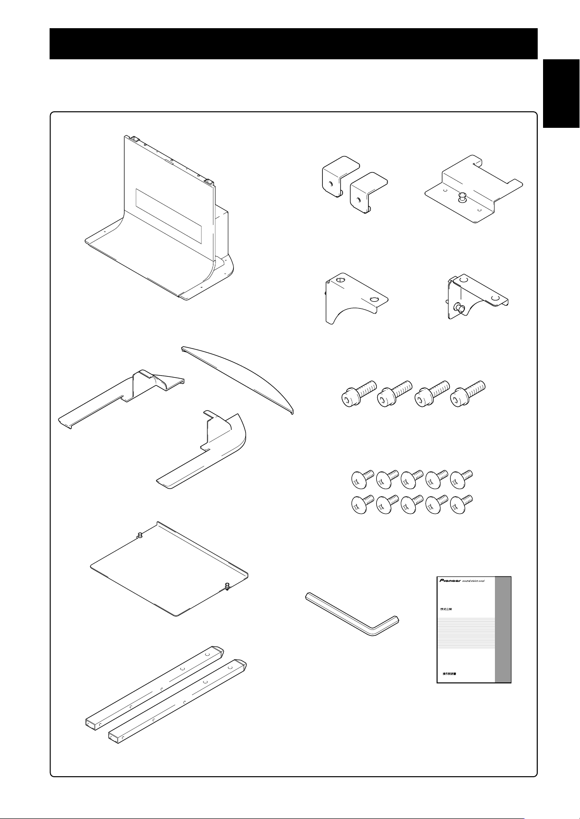
構成部品の確認
設置の前に部品を確認してください。
※ 設置の際にはプラスドライバーが必要です。
別途、ご用意ください。
日本語
本体× 1
ベースカバー L× 1
ベースカバーリア× 1
支柱ストッパー× 2
棚サポート L× 1
MR スタンド金具前× 1
棚サポート R× 1
六角穴付ボルト(M8 ×35mm)× 4
棚板× 1
支柱× 2
ベースカバー R× 1
ネジ(M5 ×10mm)× 10
六角レンチ× 1
(対辺寸法:6mm)
取扱説明書(本書)×1
フロアースタンド
Floor stand
Support de base
Bodenständer
Supporto per display
Vloerstandaard
Soporte para colocar en el suelo
PDK-FS03
取扱説明書
Operating instructions
Mode d’emploi
Bedienungsanleitung
Istruzioni per l’uso
Gebruiksaanwijzing
ucciones
Manual de instrucciones
3
Ja
Page 4
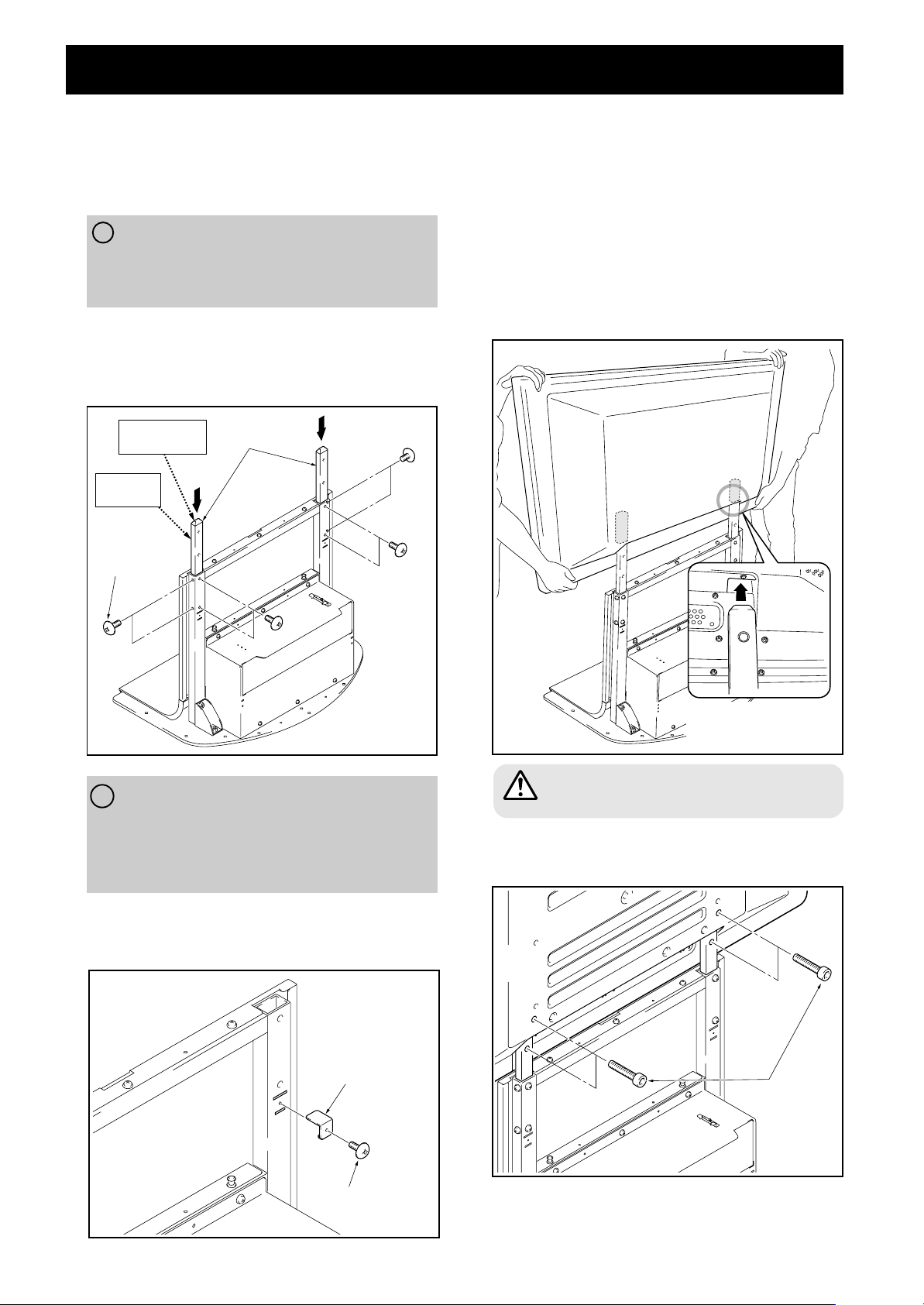
設置手順(イラストは43型です)
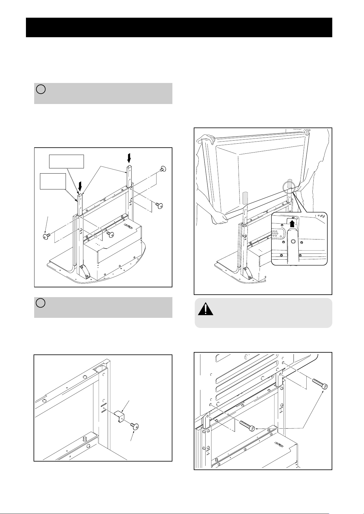
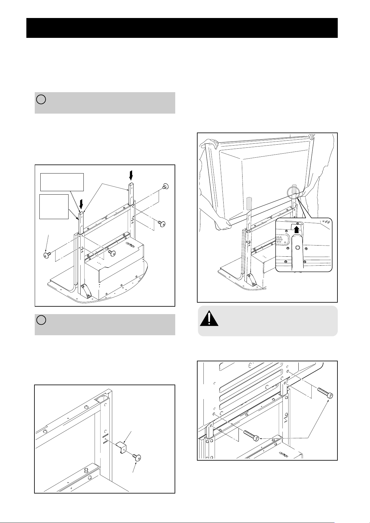
1 本体に支柱を取り付ける
取り付けるハイビジョンプラズマテレビの機種、形
態により取り付け手順が異なります。A、B より選
択し、取り付けてください。
A ハイビジョンプラズマテレビ
PDP-504HD / PDP-504HDV
PDP-434HD / PDP-434HDV
の両サイドにスピーカーを取り付ける場合
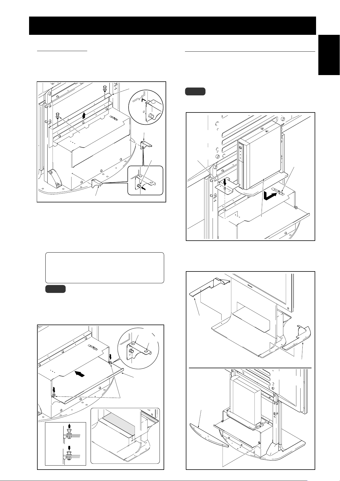
支柱を本体に差し込み、ネジ(M5× 10mm)で固定
してください(8 カ所)。
支柱は ’ 表示がある方が前、樹脂エンドキャップ(先
が細くなっている)がついている方が上になります。
エンドキャップが
ついている方が上
’表示がある
方が前
ネジ
(M5 × 10mm)
支柱
2 ハイビジョンプラズマテレビを支柱に取り付
ける
ハイビジョンプラズマテレビの下側中央の凹部にスタン
ドの支柱を合わせて、垂直にゆっくり挿入してください。
スタンドの支柱をハイビジョンプラズマテレビのスタン
ド挿入口以外の部分に当てないように注意してください。
本体裏面や端子にキズを付けたり、変形させる危険があり
ます。
ハイビジョンプラズマテレビに取っ手がある場合は、取っ
手を持つと便利です。
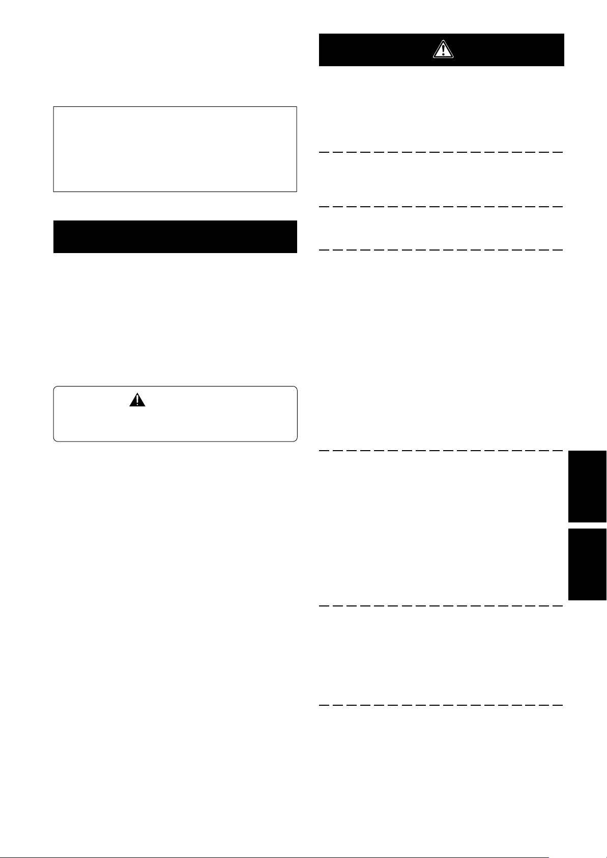
B ハイビジョンプラズマテレビ
PDP-504HD / PDP-504HDV
PDP-434HD / PDP-434HDV
の下側にスピーカーを取り付ける場合および
PDP-434BX / PDP-434TX を設置する場合
支柱ストッパーを本体背面の切り込み部に取り付け、ネ
ジ(M5 × 10mm)で固定する(左右 2 カ所)。
支柱の取り付け方は A と同様です。
支柱ストッパー
ハイビジョンプラズマテレビ
下部と支柱を図のように合わ
せる
必ず 2 人以上で取り付けてください。
指を挟み込まないように注意してください。
注意
3 六角穴付ボルトでハイビジョンプラズマテレビ
と支柱を固定する(4 カ所)
六角穴付ボルト
(M8 × 35mm)
Ja
ネジ(M5 × 10mm)
4
スピーカーを取り付ける場合は、この手順の後に取り
付けてください。
スピーカーの取り付け手順はハイビジョンプラズマテ
レビに付属されている取扱説明書を参照してください。
Page 5
設置手順
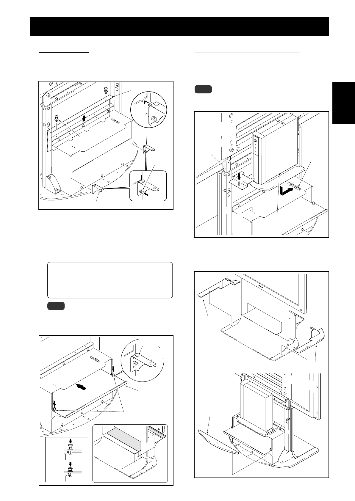
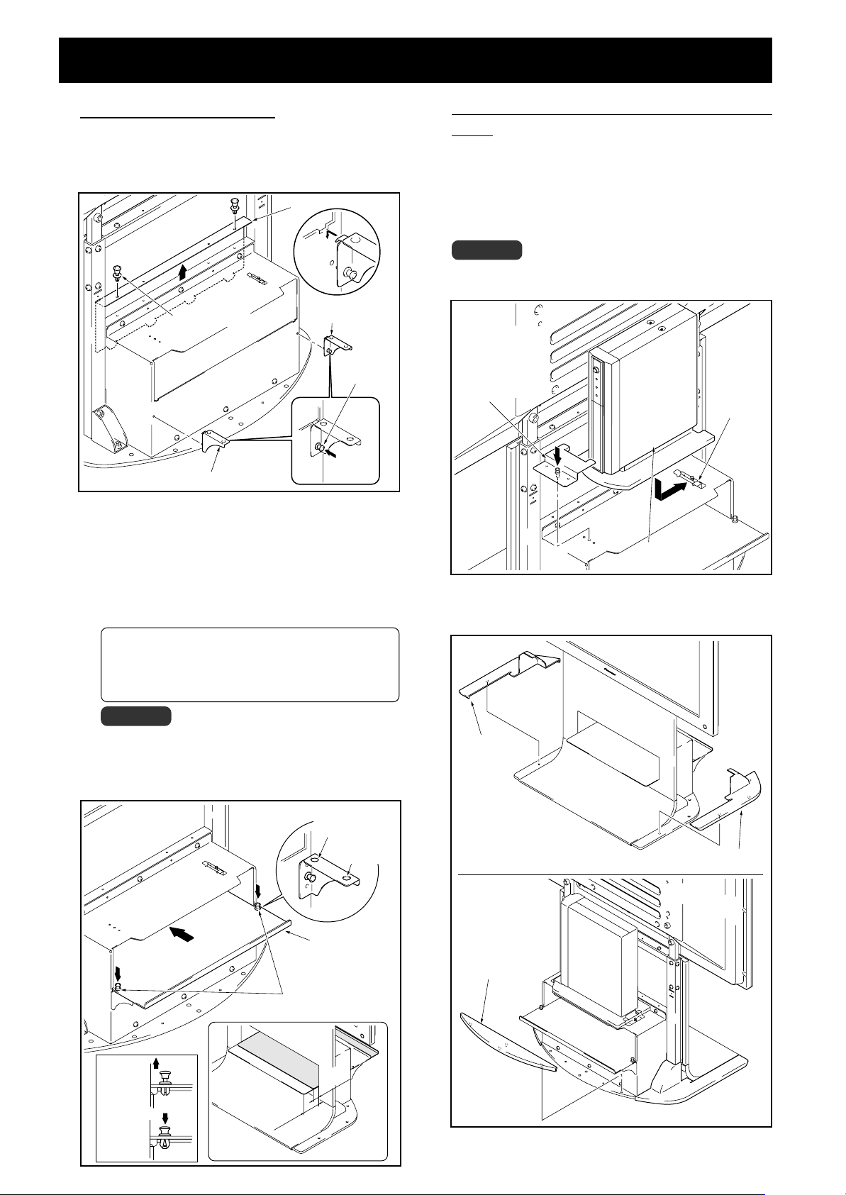
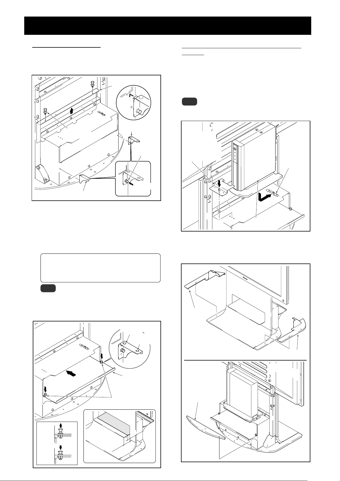
4 棚を使用する場合
本機は棚を取り付けることができます。
1 棚ぶたを取り外し、棚サポート L、R を本体にひっか
けて取り付ける。
棚ぶた
プッシュ
リベット
棚サポート L
2 棚板を後ろから差し込み、プッシュリベットで固定
する。
棚板は前か後の 2 段階の位置を選択できます。
お手持ちの機器に合わせて設定してください。
位置を変えるときは、プッシュリベットの上のつ
まみを引き上げると簡単に外せます。
棚開口部内の大きさ:420(有効幅)〈開口 436〉×
102(高さ)mm
棚の奥行き:349mm
耐荷重:10kg まで
棚サポート R
プッシュ
リベット
押し込む
5 メディアレシーバーを縦置きで取り付ける場合
縦置き用スタンドに取り付けたメディアレシーバー(取り
付け方法はハイビジョンプラズマテレビの取扱説明書を参
照してください)を後側の棚の上に置き、MRスタンド金
具前と後で縦置き用スタンドを固定する。
ご注意
メディアレシーバー以外の機器は、この位置に設置しないでく
ださい。
MR スタンド
金具前
メディア
レシーバー
MR スタンド
金具後
6 ベースカバー L、R、リアを取り付ける
ベース部に沿ってはめ込んでください。
日本語
ご注意
この棚にメディアレシーバー以外(特に AV アンプなど)
を載せるときは、放熱などを妨げる場合がありますのでご
注意ください。
詳しくは各機器の取扱説明書をご覧ください。
前位置用の穴
後位置用の穴
棚板
プッシュリベット
フリー
位置
ロック
位置
前面側
前位置
後位置
ベースカバーL
ベースカバーR
ベースカバーリア
5
Ja
Page 6
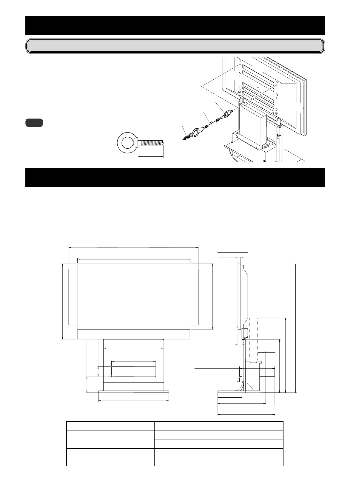
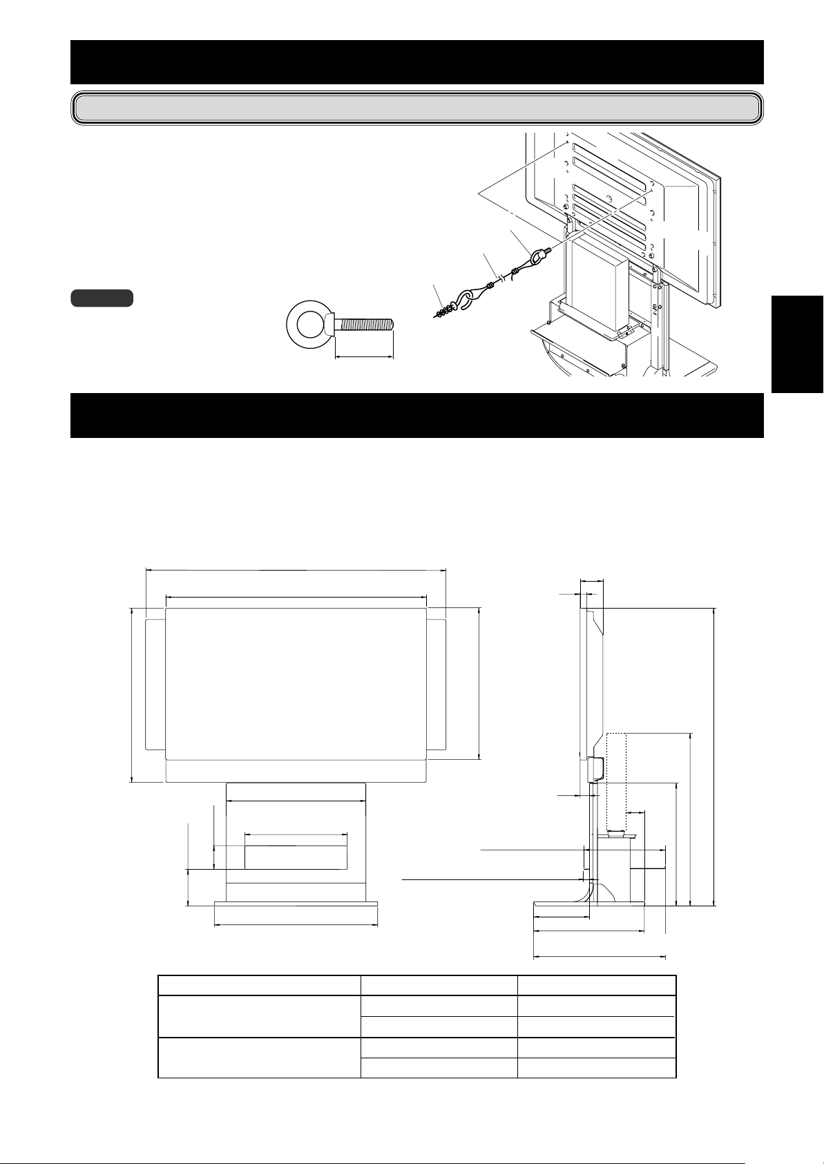
転倒防止(設置後は転倒防止の備えを必ず行ってください)
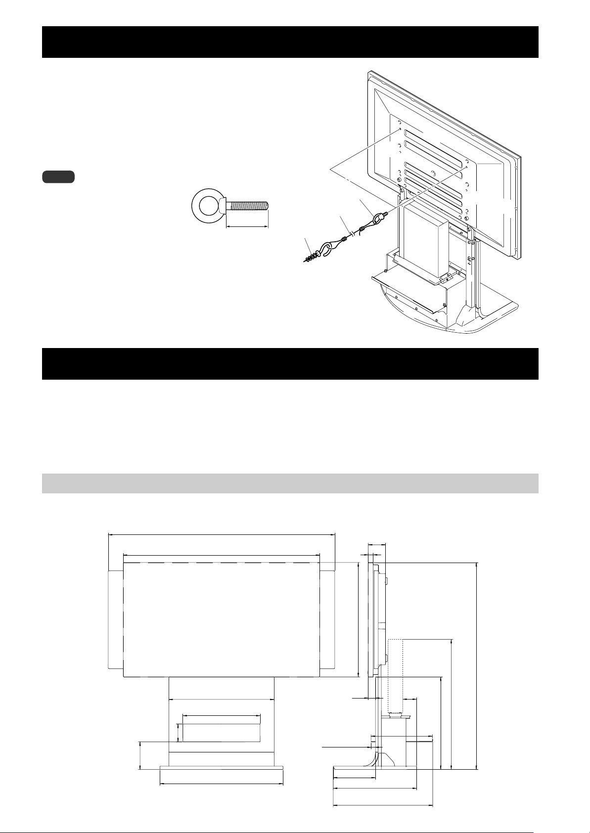
1 ハイビジョンプラズマテレビに転倒防止用ボル
ト(フック)を取り付ける
2 壁、柱などの堅牢部に、丈夫なヒモまたはくさ
りでしっかりと固定する
左右対称に 2 カ所同様の作業を行ってください。
ご注意
フック、ヒモまたはくさり、取付具は市
販品をご使用ください。
推奨フック: 呼び径 M8、
長さ 12 〜 15mm
12〜15mm
2 ヒモまたはくさり
取付具
1フック
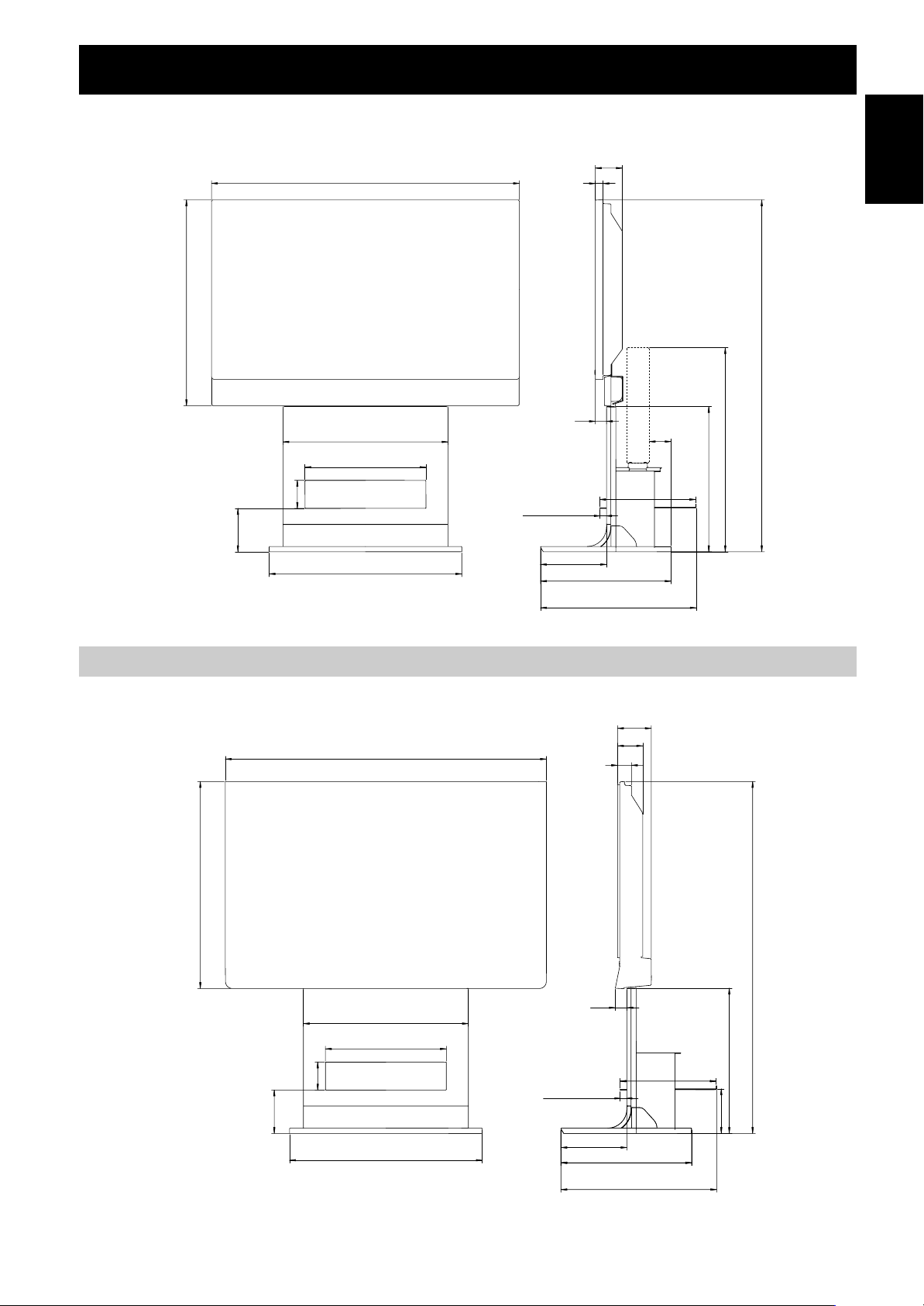
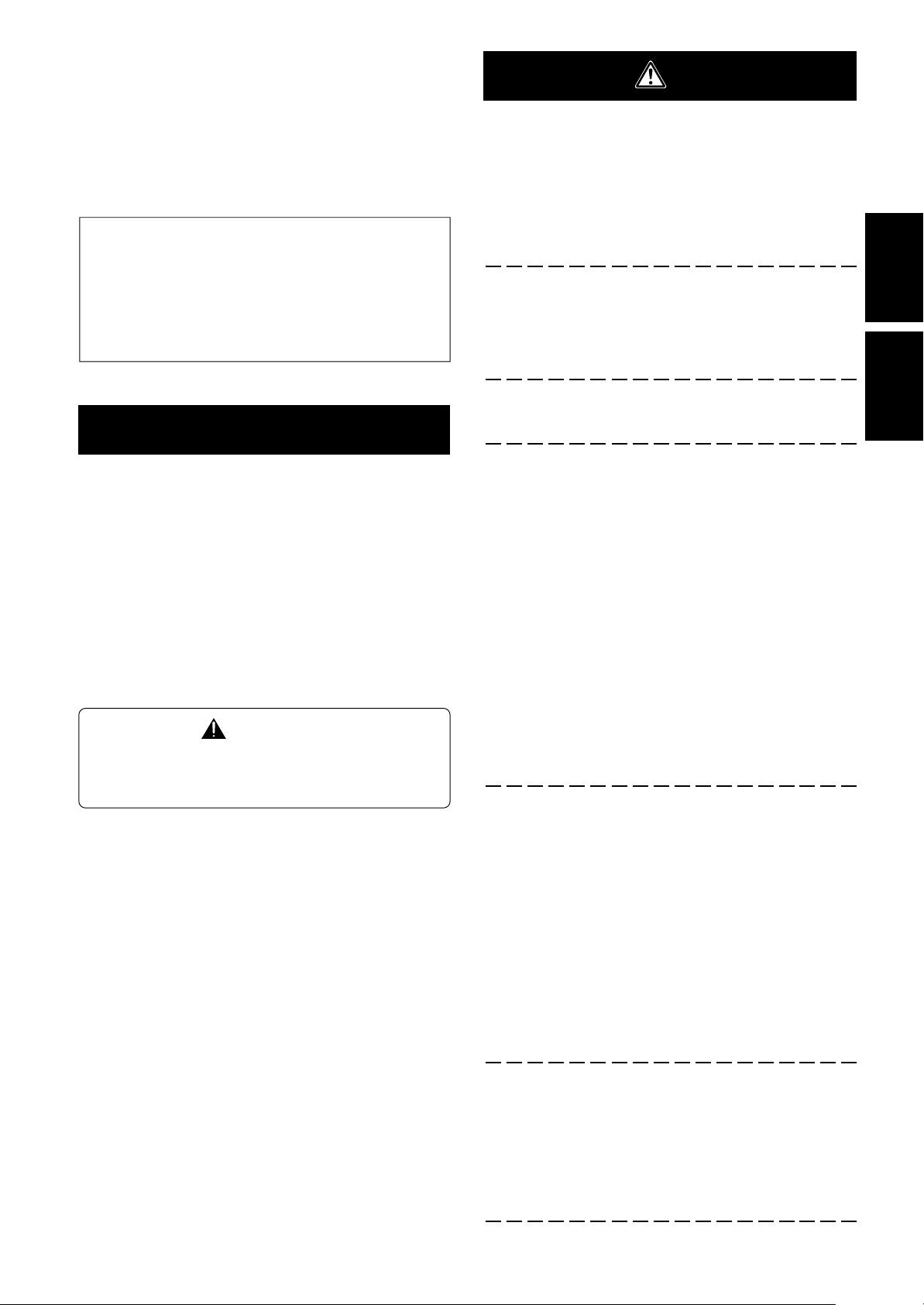
外形寸法図
質量 19.5kg
52.8kg
61.0kg
53.5kg
52.5kg
(単位:mm)
PDP-504HD / PDP-504HDV / PDP-434HD / PDP-434HD 取り付け時
本体両サイドにスピーカー取り付け時
(スタンドのみ)
(スタンド + ハイビジョンプラズマテレビ〈PDP-434HD / PDP-434HDV のディスプレイとスピーカー取付時〉)
(スタンド + ハイビジョンプラズマテレビ〈PDP-504HD / PDP-504HDV のディスプレイとスピーカー取付時〉)
(スタンド + ハイビジョンプラズマテレビ〈PDP-434BX 取付時〉)
(スタンド + ハイビジョンプラズマテレビ〈PDP-434TX 取付時〉)
1440 (PDP-504HD / PDP-504HDV)
1290 (PDP-434HD / PDP-434HDV)
1270 (PDP-504HD / PDP-504HDV)
1120 (PDP-434HD / PDP-434HDV)
98
28
Ja
737 (PDP-504HD / PDP-504HDV)
652 (PDP-434HD / PDP-434HDV)
600
420(有効幅)〈開口436〉
102
70(棚板前位置)
25(棚板奧位置)
162(棚板上面)
開口
701
6
41
240
476
517(棚板前位置)
567(棚板奧位置)
79
349(棚面)
742
1265 (PDP-504HD / PDP-504HDV)
1180 (PDP-434HD / PDP-434HDV)
528
Page 7
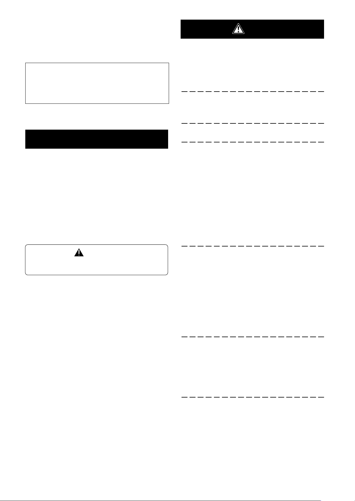
本体下側にスピーカー取り付け時
外形寸法図
1270 (PDP-504HD / PDP-504HDV)
1120 (PDP-434HD / PDP-434HDV)
833 (PDP-504HD / PDP-504HDV)
748 (PDP-434HD / PDP-434HDV)
420(有効幅)〈開口436〉
102
開口
162(棚板上面)
600
701
41
70(棚板前位置)
25(棚板奧位置)
240
517(棚板前位置)
567(棚板奧位置)
98
28
476
79
349(棚面)
1364 (PDP-504HD / PDP-504HDV)
1279 (PDP-434HD / PDP-434HDV)
742
528
日本語
PDP-434BX / PDP-434TX 取り付け時
1168
753
600
420(有効幅)〈開口436〉
102開口
162(棚板上面)
701
42
70(棚板前位置)
25(棚板奧位置)
240
517 (棚板前位置)
567 (棚板奧位置)
122.5
91.6
50.6
476
349(棚面)
1279
528
162
・仕様および外観は、改良のため予告なく変更することがあります。
2003パイオニア株式会社 禁無断転載
7
Ja
Page 8
Thank you for buying Pioneer’s product.
Please read through the Operating Instructions to learn how
to operate your model safely and properly.
Please be advised to keep the Operating Instructions in
your place for future reference.
Installation
¶ Consult your dealer if you encounter any difficulties
with this installation.
¶ Pioneer is not liable for any damage resulting from improper
installation, improper use, modification, or natural disasters.
Contents
Cautions ................................................................... 8
List of parts and equipment included ................... 9
Installation and assembly instructions ............... 10
Preventing equipment from falling over ............. 12
External dimensions diagram .............................. 12
Cautions
This product is a floor stand exclusively designed for plasma
displays (PDP-504HD / PDP-5040HD / PDP-504HDE / PDP504HDG / PDP-434HD / PDP-4340HD /PDP-434HDE / PDP434HDG / PRO-1110HD / PRO-910HD) from Pioneer. Note
that it is not designed for use with any other equipment. For
further information, please contact the store where you
purchased your display.
Do not install or modify the product other than specified.
Do not use this stand for a plasma display other than those
designated and do not modify it or use it for other purposes.
Improper installation is extremely dangerous because it
may result in it falling over or other accident.
Installation Location
• When selecting the location in which the stand is to be
placed, be sure to select a location with a surface
sufficiently strong to bear the weight of the stand and
plasma display. (Product weight is listed on p. 12.)
• Make sure the installation location is a level, flat, and
stable surface and take proper precautions when installing it to make sure its weight is evenly distributed.
• Depending on the type of surface on which the stand is
placed, the legs may leave marks on the surface, and this
should be taken into consideration when selecting the
place in which the stand is to be placed.
• Do not install it outdoors, at a hot spring, or near a beach.
• Do not install the stand where it may be subjected to
vibration or shock.
CAUTION
This symbol refers to a hazard or unsafe practice which
can result in personal injury or property damage.
Assembling and Installation
• Assemble the stand in accordance with the assembly
instructions and securely attach all screws at the
designated locations.
There have been cases where unforeseen accidents
such as the equipment breaking or falling over
occurred after the installation of the display because
the stand was not installed as instructed.
• The display must always be installed by two or more
people to assure it is installed safely.
• Before installation, turn off the power for the display
and peripheral devices then remove the power cord
plug from the power outlet.
After Installation
• Never lean on the plasma display or apply heavy pressure
to the stand.
• Prevent accidents caused by the product falling over by
taking reliable measures to prevent it from falling over
(see Page 12).
• Do not move the stand with the plasma display etc. still
attached.
En
8
Page 9

List of parts and equipment included
Be sure to check that all the parts and equipment listed below have been included before beginning to assemble your stand.
• Note that a Philips screwdriver (not included) is required for assembly.
• Stand x1
• Base cover L x1
• Base cover rear x1
• Support column stopper x2
• Shelf support L x1
• MR stand, front metal fitting x1
• Shelf support R x1
• Hexagonal bolts (M8 x 35mm [1-3/8 inch]) x4
English
• Shelf panel x1
• Support column x2
• Base cover R x1
• Screw (M5 x 10 mm [13/32 inch]) x10
• Hexagonal wrench x1
(Opposite side 6 mm for M8 use)
• Operating instructions
(this document) x1
フロアースタンド
Floor stand
Support de base
Bodenständer
Supporto per display
Vloerstandaard
Soporte para colocar en el suelo
PDK-FS03
取扱説明書
Operating instructions
Mode d’emploi
Bedienungsanleitung
Istruzioni per l’uso
Gebruiksaanwijzing
ucciones
Manual de instrucciones
9
En
Page 10
I
nstallation and assembly instructions
1
Attaching the support columns to the stand.
The attachment procedure varies according to the type
and form of the plasma display to be attached. Perform this attachment using either procedure A or B.
A When installing speakers on both sides of the
plasma display
Insert the support columns into the stand and fix them in
place with screws (M5 x 10mm [13/32 inch]). (8 locations)
Install each support column so that the side with the symbol
’
is forward and the end with the plastic end cap (pointed) is
upwards.
2
(43-inch display model in the figure)
Attach plasma display to support column.
Fit the stand’s support columns into the slots in the center of
the bottom of the plasma display then slowly insert them
directly into the slots. Be extremely careful not to insert the
support columns of the stand into any part of the plasma
display other than the stand insertion slots. Note that doing so
might damage the plasma display panel or its ports or result in
the warping of the stand.
If the plasma display is fitted with handles, it is usually best to
hold the display by its handles when attaching it to the
support column.
End with end cap
points upwards.
Side with the
symbol ’ is
forward.
Screw
(M5 x 10 mm
[13/32 inch])
Support column
B When installing speakers at the bottom of the
plasma display
Attach the support column stoppers to the notches on the back
of the stand and fix them in place with screws (M5 x 10mm [13/
32 inch]). (2 locations on the right and left)
The same applies to support column attachment method A.
Line up the column supports
with the bottom of the plasma
display as indicated in the
accompanying diagram.
Be sure to work with at least one other person
when attaching the display.
Caution
3
Use the hexagonal bolts to fix the plasma display to
Be careful not to allow your fingers get caught
between the display and support column.
the support column (4 locations).
10
En
Support column
stopper
Screw
(M5 x 10 mm [13/32 inch])
Hexagonal
bolts
(M8 x 35 mm
[1-3/8 inch])
It you are attaching speakers, do so at this stage.
See the installation instructions provided with your
speakers for instructions on how to install them.
Page 11
4
When using a shelf.
A shelf can be attached to the stand.
1 Remove the shelf cover and then attach the shelf supports
L and R to the stand.
Shelf cover
I
nstallation and assembly instructions
5
When attaching a media receiver upright.
Put the media receiver installed on a upright use stand (see
the plasma display operating instructions for the installation
method) on the shelf at the rear and fix the upright use stand
in place with the MR stand’s front and back metal fittings.
Note
Do not install any device other than a media receiver in this
position.
English
Push rivet
Shelf support R
Push rivet
Push in
Shelf support L
2 Push the shelf panel in from behind and fix it in place with
the push rivet.
The shelf panel installation position be selected from
two levels: either the front or the back.
Set it accorrding to the device you have.
When changing its position, you can easily remove it
by pulling up the knob on the top of the push rivet.
Interior dimensions of the shelf opening: 420 mm [16-
17/32 inch] (effective width) <opening 436 [17-5/32] >
x 102 mm [4-1/32 inch] (height)
Depth of the shelf: 349 mm [13-3/4 inch]
Bearing capacity: up to 10 kg [20.1 lbs]
MR stand’s front
metal fitting
6
Installing base covers L, R, and rear.
Insert them along the base.
MR stand’s
back metal
fitting
Media receiver
Note
Be careful when installing anything other than a media
receiver (particularly an AV amplifier etc.) on this shelf,
because it may block heat discharge etc. For details, see
the instruction manual for each device.
Hole for front
position use
Hole for back
position use
Shelf panel
Push rivet
Unlocked
position
Locked
position
Front side
Front
position
Back
position
Base cover L
Base cover R
Base cover rear
11
En
Page 12
Preventing equipment from falling over
After installing the stand, be sure to take measures so that the equipment will not fall over.
1
Attaching falling prevention bolts (hooks) to the
plasma display.
2
Using strong cords or chains to firmly stabilize it to
a wall, pillar, or other sturdy element.
Perform the same procedure on the left and right, making
sure when doing so that the lengths and positions of both
restraints are symmetrical.
2 Cord or chain
1 Hook
Note
Use hooks, ropes, chains, and fittings that
are available on the market.
Recommended hook:
Nominal diameter M8
Length 12 to 15 mm (15/32 inch)
12–15mm
(15/32 inch)
Fitting
External dimensions diagram
Weight
Stand only: 19.5 kg (43.0 lbs)
Stand and plasma display: 52.8 kg (116.4 lbs) [When used with a PDP-434HD / PDP-4340HD / PDP-434HDE / PDP-
434HDG /PRO-910HD display with speakers attached.]
61.0 kg (134.5 lbs) [When used with a PDP-504HD / PDP-5040HD / PDP-504HDE / PDP504HDG / PRO-1110HD display with speakers attached.]
Unit: mm (inch)
1440 (56-11/16) [50 inch display model]
1290 (50-25/32) [43 inch display model]
1270 (50) [50 inch display model]
1120 (44-3/32) [43 inch display model]
98 (3-27/32)
28 (1-3/32)
737 (29-1/32) [50 inch display model]
833 (32-13/16) [50 inch display model]
748 (29-7/16) [43 inch display model]
600 (23-5/8)
420 (16-17/32) [effective width]
<Opening 436 (17-5/32)>
Opening 102 (4-1/32)
162 (16-3/8) [Top of shelf panel]
Plasma display
PDP-434HD / PDP-4340HD / PDP-434HDE /
PDP-434HDG / PRO-910HD
PDP-504HD / PDP-5040HD / PDP-504HDE /
PDP-504HDG / PRO-1110HD
701 (27-19/32)
25 (31/32) [Shelf panel front position]
70 (2-3/4) [Front panel deep position]
Location of speakers
At sides of plasma display
Below plasma display
At sides of plasma display
Below plasma display
652 (25-21/32) [43 inch display model]
41 (1-5/8)
349 (1 3- 3/ 4) [shelf surface]
240 (7-7/16)
476 (18-3/4)
517 (20-11/32) [Shelf panel front position]
567 (22-5/16) [Front panel deep position]
Full height(Dimensions A)
1,180 (46-15/32)
1,279 (50-11/32)
1,265 (49-13/16)
1,364 (53-11/16)
• The above specifications and exterior may be modified without prior notice to improve the product.
12
En
A
79 (3-1/8)
742 (29-7/32)
528 (20-25/32)
Published by Pioneer Corporation.
Copyright © 2003 Pioneer Corporation.
All rights reserved.
Page 13
Nous vous remercions d’avoir procéder à l’achat d’un
produit Pioneer.
Veuillez lire attentivement ce Mode d’emploi pour savoir
comment opérer correctement et en toute sécurité votre
modèle.
Nous vous conseillons de conserver soigneusement de
Mode d’emploi dans un endroit sûr et à proximité afin de
pouvoir vous y référer le cas échéant.
Installation
¶ Veuillez consulter votre revendeur si vous rencontrez
des difficultés lors de l’installation.
Pioneer n’assumera aucune responsabilité pour tout
dommage résultant d’une installation incorrecte, d’une
utilisation incorrecte, une modification de ce produit ou
encore de désastres naturels.
Table des matières
Attention ................................................................ 13
Liste des pièces et équipements inclus .............. 14
Instructions concernant l’installation et
l’assemblage du dispositif.........................................
Prévenir le basculement et la chute de
l’équipement.......................................................... 17
Dimensions extérieures ........................................ 17
ATTENTION
Ce symbole indique un danger ou une pratique dangereuse
risquant de compromettre la sécurité qui peut provoquer des
blessures ou des dégâts matériels.
15
Attention
Ce produit est un support de base conçu exclusivement
pour les écrans d’affichage plasma (PDP-504HD / PDP5040HD / PDP-504HDE / PDP-504HDG / PDP-434HD / PDP4340HD /PDP-434HDE / PDP-434HDG / PRO-1110HD / PRO910HD) fabriqués par la société PIONEER. Veuillez noter
que ce support de base n’a pas été conçu pour être utilisé
avec d’autres équipements. Pour de plus amples informations, veuillez contacter le revendeur où vous avez acheté
votre écran d’affichage.
Veuillez ne pas installer le produit d’une manière autre que
celle spécifiée ou modifier ce dernier. En outre, veuillez ne
pas utiliser ce support pour un écran d’affichage plasma
autre que ceux pour lesquels il a été conçu et ni le modifier
ou l’utiliser à des fins autres que celles pour lesquelles il a
été conçu.
Une installation incorrecte est extrêmement dangereuse
car celle-ci peut provoquer le basculement du support ou un
autre accident.
Emplacement d’installation
•
Lorsque vous choisissez l’emplacement où sera placé le
support de base, veillez à sélectionner un endroit avec
une surface de base suffisamment solide pour supporter
le poids du support de base et de l’écran d’affichage
plasma (Le poids du produit est indiqué sur le Tableau
figurant à la page 17.)
•
S’assurer que l’emplacement d’installation est bien plane
et à niveau et prendre toutes les précautions utiles et
indispensables lors de l’installation du support afin de
veiller à ce que le poids soit bien uniformément réparti.
•
Selon le type de surface sur lequel sera placé le support
de base, les pieds pourront éventuellement laisser des
traces sur ladite surface et ceci devra être prendre en
considération lorsque l’on sélectionnera l’endroit où sera
installé le support de base.
• Ne pas installer le support à l’extérieur, à proximité d’une
source thermale ou sur la plage.
• Ne pas installer le support à un endroit où il pourrait être
soumis à des chocs ou à des vibrations.
Assemblage et installation
• Assembler le support conformément aux instructions
concernant l’assemblage et fixer solidement toutes
les vis aux endroits prévus à cet effet.
On a constaté des cas où des accidents imprévus
sont survenus (endommagement de l’équipement,
chute, etc.) après l’installation de l’écran d’affichage
parque le support n’avait pas été installé comme
indiqué dans les instructions.
• L’écran d’affichage doit toujours être installé au
moins par deux personnes afin de veiller à ce qu’il
soit installé en toute sécurité.
• Avant de procéder à l’installation, mettre l’écran ainsi
que les équipements périphériques hors tension en
coupant l’alimentation, puis retirer la prise du câble
d’alimentation électrique de la prise femelle murale.
English
Français
Après installation
•
Ne jamais s’appuyer sur l’écran d’affichage plasma ou
appliquer une forte pression sur le support de base.
•
Il convient de prévenir les accidents causés par la chute
du produit en prenant des mesures fiables pour éviter le
basculement et la chute (Voir page 17).
•
Ne pas déplacer le support de base avec l’écran
d’affichage plasma, etc. fixé sur celui-ci.
13
Fr
Page 14

Liste des pièces et équipements inclus
Veuillez vous assurer que toutes les pièces et tous les équipements indiqués ci-dessous sont bien contenus dans le carton
avant de commencer à monter le support de base.
• Veuillez prendre note qu’un tournevis de type Philips (non inclus avec les pièces) pour vis à empreinte cruciforme est
nécessaire pour assembler le support de base.
•
•
Support de base x 1 unité
•
Butée d’arrêt de la colonne de
support x 2 unités
•
Support d’étagère Gauche x 1
unité
Support MR, pièce métallique de
fixation x 1 unité
•
Support d’étagère Droite x 1 unité
•
Couvercle de base Arrière x 1 unité
•
Couvercle de base Gauche x 1 unité
•
Panneau étagère x 1 unité
•
Boulons à six pans ( M8 x 35 mm) x 4 unités
•
Vis (M5 x 10 mm) x 10 unités
•
Couvercle de base Droite x 1 unité
• Clé hexagonale x 1 unité
(Côté opposé 6 mm pour utilisation M8)
Mode d’emploi
(ce document) x 1 exemplaire
フロアースタンド
Floor stand
Support de base
Bodenständer
Supporto per display
Vloerstandaard
Soporte para colocar en el suelo
PDK-FS03
14
•
Colonne de support x 2 unités
Fr
取扱説明書
Operating instructions
Mode d’emploi
Bedienungsanleitung
Istruzioni per l’uso
Gebruiksaanwijzing
ucciones
Manual de instrucciones
Page 15

Instructions concernant l’installation et l’assemblage du dispositif
(Modèle d’écran de 43 pouces comme indiqué sur la figure)
1
Fixer les colonnes de support au support de base.
La procédure d’installation varie en fonction du type
et de la forme de l’écran d’affichage plasma qui doit
être monté. Veuillez procéder à l’installation en
utilisant soit la procédure A soit la procédure B.
A Lors de l’installation des haut-parleurs des
deux côtés de l’écran d’affichage plasma.
Introduire les deux colonnes de support dans le support de
base et les mettre en place en les immobilisant avec les vis
(M5 x 10 mm). (8 emplacements)
Installer chaque colonne de support de telle sorte aue le côté
avec le symbole de la flèche verticale
l’extrémité avec le couvercle en plastique d’extrémité pointée
vers le haut.
Extrémité avec le
couvercle en
plastique d’extrémité
pointée vers le haut.
Le côté avec
le symbole de
la flèche
’
est pointé
vers l’avant.
Colonne de support
’
soit vers l’avant et
2
Fixer l’écran d’affichage plasma sur la colonne de
support.
Placer les colonnes de support du support dans les fentes au
centre de la partie inférieure puis les insérer lentement et
directement dans les fentes. Veillez très soigneusement à ne
pas insérer les colonnes de support du support dans une
quelconque partie de l’écran d’affichage plasma autres que les
fentes prévues à cet effet. Veuillez noter que si vous faites
cela vous risquez d’endommager l’écran d’affichage ou les
entrées ou encore le support.
Si l’écran d’affichage plasma est équipé de poignées, il est
généralement préférable de tenir l’écran avec ses poignées
lorsqu’on l’installe à la colonne de support.
Français
Vis (M5 x 10 mm)
B Lors de l’installation des haut-parleurs à la base
inférieure de l’écran d’affichage plasma
Fixer les butées d’arrêt de la colonne dans les fentes prévues
à cet effet à l‘arrière du support et les fixer en place avec les
bis (M5 x 10 mm) (à deux emplacements à gauche et à
droite).
La même chose s’aplique à supporter la méthode
d’installation de la colonne A.
Aligner les supports de colonne
avec la partie inférieure de
l’écran d’affichage d’écran
comme indiqué sur le
diagramme ci-joint.
Lorsque l’on installe l’écran d’affichage, veuillez
procéder au moins avec une autre personne aux
Attention
3
Utiliser les boulons à six pans pour fixer l’écran
opérations de montage du dispositif.
Veillez à ne pas coincer vos doigts entre l’écran
d’affichage et la colonne de support.
d’affichage plasma sur la colonne de support (à
quatre emplacements).
Butée d’arrêt de la
colonne de support
Vis (M5 x 10 mm)
Boulons
hexagonaux à
six pans
(M8 x 35 mm)
Si vous souhaitez installer des haut-parleurs, veuillez le faire
au cours de cette étape de l’installation.
Veuillez vous référer au Mode d’emploi fourni avec les
haut-parleurs en ce qui concerne la procédure d’installation
des haut-parleurs.
15
Fr
Page 16
Instructions concernant l’installation et l’assemblage du dispositif
5
4
Lorsque l’on utilise une étagère.
Une étagère peut être montée sue le support de base.
1 Retirer le couvercle de l’étagère Retirer le couvercle de
l’étagère puis installer les supports de l’étagère gauche et
droit sur le support de base.
Couvercle de l’étagère
Support droit de
Rivet à poussoir
l’étagère
Lorsque l’on installe transversalement un récepteur
média.
Placer le récepteur média sur un support pour l’utilisation
transversale (Voir le Mode d’emploi de l’écran d’affichage
plasma) pour les instructions concernant la méthode
d’installation) sur l’étagère à l’arrière et installer le support
pour l’utilisation transversale avec les pièce de support
métalliques MR avant et arrière.
Remarque
Ne pas installer d’autre dispositif que le récepteur média à cette
position.
Rivet à
poussoir
Pousser
Support gauche de l’étagère
à fond
2 Pousser le panneau de l’étagère à partir de l’arrière et le
mettre en place avec le rivet poussoir.
La position d’installation du panneau de l’étagère doit
être sélectionné pour l’un des deux niveaux soit le
niveau avant soit le niveau arrière.
L’installer en fonction du dispositif dont vous disposez.
Lorsque l’on change sa position, vous pouvez aisément
le retirer en enlevant le bouton sur la partie supérieure
du rivet poussoir.
Dimensions intérieures de l’ouverture intérieure de
l’étagère : 420 (efficace largeur) [Ouverturer 436] x 102
(hauteur) mm
Profondeur de l’étagère : 349 mm
Poids maxi (capacité de support) : jusqu’à 10 kg
Remarque
Soyez prudent lorsque vous installez autre chose que le
récepteur média (en particulier un amplificateur média,
etc.) sur l’étagère car cela pourrait réduire le dégagement
de la chaleur, etc. Pour de plus amples détails, veuillez vous
référer au Mode d’emploi pour chaque dispositif concerne.
Orifices pour
l’utilisation en
position avant
Orifices pour
l’utilisation en
position arrière
Pièce de fixation
métallique arrière
du support MR
Récepteur média
6
Installation des couvercles de base gauche et droit.
Pièce de
fixation
métallique
avant du
support MR
Les introduire le long de la base.
Couvercle de
base gauche
Couvercle de base droit
16
Panneau étagère
Couvercle de
base arrière
Rivet poussoir
Position
déverrouillée
Position
Position
verrouillée
Fr
Côté avant
avant
Position
arrière
Page 17
Prévenir le basculement et la chute de l’équipement
Après avoir installé le support, veillez à prendre des mesures pour que l’équipement ne tombe pas.
1
Fixation des boulons empêchant la chute (crochets)
à l’écran plasma.
2
Utiliser des câbles solides ou des chaînes pour
stabiliser solidement le dispositif à un mur, un pilier
ou autres éléments stables.
Veuillez procéder de même pour la procédure à gauche et à
droite en veillant à ce que la longueur et les emplacements
des deux côtés soient symétriques.
Remarque
Utiliser des crochets, des chaînes et d’autres
dispositifs de fixation qui sont en vente
dans le commerce.
Crochet recommandé : Diamètre nominal
M8, longueur : de 12 à 15 mm.
12–15mm
2 Câble ou chaîne
Attache
1 Crochet
Dimensions extérieures
Poids
Le support uniquement : 19,5 kg
Le support de base et l’écran plasma : 52,8 kg [lorsque l’on utilise des écrans d’affichage avec les haut-parleurs du type PDP-434HD / PDP-
4340HD / PDP-434HDE / PDP-434HDG / PRO-910HD ].
61,0 kg [lorsque l’on utilise des écrans d’affichage avec les haut-parleurs du type PDP-504HD / PDP5040HD / PDP-504HDE / PDP-504HDG / PRO-1110HD].
Unités : mm
1440 (Ecran d'affichage 50 pouces)
1290 (Ecran d'affichage 43 pouces)
1270 (Ecran d'affichage 50 pouces)
1120 (Ecran d'affichage 43 pouces)
98
28
Français
737 (Ecran d'affichage 50 pouces)
833 (Ecran d'affichage 50 pouces)
748 (Ecran d'affichage 43 pouces)
Ouverture 102
162 (partie supérieure du
panneau frontal)
Ecran d’affichage plasma Emplacement des haut-parleurs
PDP-434HD / PDP-4340HD / PDP-434HDE /
PDP-434HDG / PRO-910HD
PDP-504HD / PDP-5040HD / PDP-504HDE /
PDP-504HDG / PRO-1110HD
600
420 (Efficace largeur)
[Ouverture 436]
701
25 (Position frontale du panneau de l’étagère)
70 (Position en profondeur de l’étagère)
Sur les côtés de l’écran d’affichage
En-dessous de l’écran d’affichage
Sur les côtés de l’écran d’affichage
En-dessous de l’écran d’affichage
652 (Ecran d'affichage 43 pouces)
41
349 (surface de l’étagère)
240
476
517 (Position frontale du panneau de l’étagère)
567 (Position en profondeur de l’étagère)
Hauteur totale (dimensions A)
1.180
1.279
1.265
1.364
A
79
742
528
• Les caractéristiques techniques indiquées ci-dessus et les dimensions extérieures peuvent êtres modifiées sans préavis en vue
d’améliorer le produit.
Publication de Pioneer Corporation.
© 2003 Pioneer Corporation.
Tous droits de reproduction et de traduction réservés.
17
Fr
Page 18
Wir danken Ihnen, dass Sie sich für den Kauf eines
Produkts der Firma Pioneer entschieden haben.
Bitte lesen die Bedienungsanleitung aufmerksam, um sich
über die sichere und richtige Bedienung Ihres Modells zu
informieren.
Wir empfehlen Ihnen, die Bedienungsanleitung
anschließend sicher aufzubewahren, um Sie später im
Bedarfsfalle zu Rate ziehen zu können.
Installation
¶ Bitte setzen Sie sich mit Ihrem Händler in Verbindung,
wenn Sie auf Schwierigkeiten bei der Installation
stoßen.
Die Firma Pioneer haftet nicht für Schäden, die auf falsche
Installation, auf inkorrekte Verwendung, auf vorgenommene
Veränderungen oder auf Naturkatastrophen zurückzuführen
sind.
Installationsort
•
Vergewissern Sie sich bei der Auswahl des Platzes, an
dem Sie den Bodenständer aufstellen wollen, dass dieser
Platz stabil genug ist, das Gewicht des Ständers und des
Plasmadisplays zu tragen (das jeweilige Produktgewicht
ist auf Seite 22 aufgelistet).
•
Vergewissern Sie sich, dass der Installationsort eine
waagerechte, ebene und stabile Fläche ist und treffen Sie
beim Installieren die richtigen Vorkehrungen, dass Sie
sicher sein können, dass das Gewicht gleichmäßig
verteilt wird.
• Je nach der Beschaffenheit der Fläche, auf der der
Bodenständer aufgestellt wird, können die Beine
Eindrücke auf der betreffenden Oberfläche hinterlassen.
Das sollte bei der Auswahl des Platzes, an dem der
Bodenständer aufgestellt werden soll, berücksichtigt
werden.
• Installieren Sie den Ständer nicht im Freien, in der Nähe
einer heißen Quelle oder in Strandnähe.
• Installieren Sie den Ständer nicht an Orten, an denen er
Vibrationen oder Stößen ausgesetzt ist.
Inhalt
Sicherheitshinweise .............................................. 18
Auflistung der zugehörigen Teile und des
sonstigen Zubehörs .............................................. 19
Installations– und Montageanweisungen .......... 20
Mittel zur Verhütung des Umstürzens ................ 22
Außenabmessungen ............................................. 22
Vorsicht!
Dieses Symbol kennzeichnet eine gefährliche oder riskante
Vorgehensweise, die zu eigenen Verletzungen, zu
Verletzungen anderer Personen oder zu Sachschäden führen
kann.
Sicherheitshinweise
Dieses Produkt ist ein Bodenständer, der ausschließlich für
die Plasmadisplays der Firma Pioneer (PDP-504HD / PDP-
5040HD / PDP-504HDE / PDP-504HDG / PDP-434HD / PDP4340HD /PDP-434HDE / PDP-434HDG / PRO-1110HD / PRO910HD) bestimmt. Bitte beachten Sie, dass er nicht für den
Gebrauch mit einem anderen Gerät vorgesehen ist. Bitte
setzen Sie sich hinsichtlich weiterer Informationen mit der
Handelseinrichtung in Verbindung, in der Sie Ihr Display
gekauft haben.
Montage und Installation
• Montieren Sie den Ständer gemäß den
Montageanweisungen und befestigen Sie alle
Schrauben sicher an den jeweils vorgesehenen
Positionen.
Es hat Fälle gegeben, in denen es nach der Installation des Displays zu unvorhergesehenen Unfällen wie
beispielsweise einem Bruch oder zum Umfallen kam,
weil der Ständer nicht wie vorgeschrieben installiert
wurde.
• Das Display muss stets von zwei oder mehr Personen
installiert werden, um zu sichern, dass es sicher
installiert wird.
• Schalten Sie das Display und periphere Geräte vor
der Installation aus und trennen Sie es bzw. sie durch
Herausziehen des Steckers aus der Steckdose vom
Netz.
Nach der Installation
•
Stützen Sie sich auf keinen Fall auf das Plasmadisplay
und üben Sie niemals starken Druck auf den
Bodenständer aus.
•
Beugen Sie Unfällen durch das Umfallen des Produkts
vor, indem Sie zuverlässige Maßnahmen treffen, die es
vor dem Umfallen bewahren (siehe Seite 22).
•
Bewegen Sie den Bodenständer nicht mit den bereits
oder noch montierten Plasmadisplay.
Installieren Sie das Produkt nicht anders als angegeben und
nehmen Sie keine Änderungen am Produkt vor. Verwenden
Sie diesen Ständer nicht für ein anderes Plasmadisplay als
für das, für das es vorgesehen ist, verändern Sie ihn nicht
und verwenden Sie ihn nicht für andere Zwecke.
Eine falsche Installation ist sehr gefährlich, da sie zum
Umfallen des Displays oder einem anderen Unfall führen
kann.
18
Ge
Page 19

Auflistung der zugehörigen Teile und des sonstigen Zubehörs
Vergewissern Sie sich, ehe Sie mit der Installation ihres Bodenständers beginnen, dass alle unten dargestellten Teile und das
sonstige Zubehör vorhanden sind.
• Bitte beachten Sie, dass für die Montage ein Kreuzschlitzschraubenzieher (nicht enthalten) erforderlich ist.
•
• Bodenständer: 1
Stützsäulensperre: 2
•
Auflagestütze L: 1
•
Ständer für Medien-Receiver (MR),
vorderes Metallpassteil: 1
•
Auflagestütze R: 1
•
Grundplattenabdeckung L: 1
•
Auflageplatte: 1
•
Grundplattenabdeckung Rückseite: 1
•
Grundplattenabdeckung R: 1
Sechskant-Stiftschlüssel: 1
(gegenüberliegende Seite 6 mm für
M8-Schrauben)
•
Innensechskantschrauben (M8 x 35 mm): 4
•
Schrauben (M5 x 10 mm): 10
Bedienungsanleitung
(dieses Dokument): 1
フロアースタンド
Floor stand
Support de base
Bodenständer
Supporto per display
Vloerstandaard
Soporte para colocar en el suelo
PDK-FS03
Deutsch
•
Stützsäulen: 2
取扱説明書
Operating instructions
Mode d’emploi
Bedienungsanleitung
Istruzioni per l’uso
Gebruiksaanwijzing
ucciones
Manual de instrucciones
19
Ge
Page 20

Installations– und Montageanweisungen (In der Abbildung ist ein 43-Zoll-Modell dargestellt)
1 Montage der Stützsäulen am Bodenständer
Die Verfahrensweise der Montage der Stützsäulen
unterscheidet sich je nach dem Typ und der Form des
zu montierenden Plasmadisplays. Führen Sie die Montage aus, indem Sie entweder das Verfahren A oder
das Verfahren B anwenden.
A
Installation der Lautsprecher auf beiden Seiten des
Plasmadisplays
Führen Sie die Stützsäulen in den Bodenständer ein und
schrauben Sie die betreffenden Stützsäulen wie
vorgesehen mit Schrauben (M5 x 10 mm) fest (8
Positionen).
Montieren Sie jede Stützsäule so, dass die Seite mit dem
Symbol
’
nach vorn zeigt und das Ende mit der Kunststoff-
Abdeckklappe (wie angezeigt) nach oben gerichtet ist.
Ende der
Abdeckklappe ist
nach oben gerichtet.
Seite mit
dem Symbol
’
zeigt nach
vorn.
Schraube
(M5 x 10 mm)
Colonne de support
2
Befestigen Sie das Plasmadisplay an der Stützsäule.
Passen Sie die Stützsäulen des Ständers den Öffnungen in
der Mitte unten am Plasmadisplay an und führen Sie sie dann
langsam direkt in die Öffnungen ein. Achten Sie bitte
unbedingt darauf, dass sie die Stützsäulen des Ständers nicht
in irgendeinen anderen Teil des Ständers einführen als in die
dafür vorgesehenen Öffnungen. Wenn Sie dies nicht
beachten, besteht die Gefahr, dass Sie das Bedienfels des
Plasmadisplays beschädigen oder seine Anschlussbuchsen
oder dass sich der Ständer verzieht.
Wenn das Plasmadisplay mit Griffen versehen ist, ist es
gewöhnlich das Beste, das Display an den Griffen zu halten,
wenn es an der Stützsäule befestigt wird.
B
Installation der Lautsprecher unter dem
Plasmadisplay
Positionieren Sie die Stützsäulensperren in den dafür
vorgesehenen Nuten auf der Rückseite des Bodenständers
und schrauben Sie sie mit Schrauben (M5 x 10 mm) fest (2
Positionen rechts und links).
Dasselbe gilt für die für die Stützsäulen-Montagemethode A.
Stüzsäulensperre
Bringen Sie die Stützsäulen in
Übereinstimmung mit dem
unteren Teil des Plasamdisplays,
wie es in der zugehörigen
Abbildung dargestellt ist.
Arbeiten Sie bei der Befestigung des Displays
unbedingt mit mindesten einer anderen Person
Vorsicht!
3
Verwenden Sie zur Montage des Plasmadisplays an
zusammen.
Achten Sie sorgsam darauf, dass ihre Finger nicht
zwischen das Plasmadisplay und die Stützsäule
gelangen.
den Stützsäulen die vorgesehenen
Innensechskantschrauben (4 Positionen).
Innensechskantschrauben
(M8 x 35 mm)
20
Ge
Schraube (M5 x 10 mm)
Montieren Sie die Lautsprecher in diesem Stadium der Installation.
Zur Verfahrensweise der Installation der Lautsprecher
siehe die mit Ihren Lautsprechern mitgelieferten
Installationsanweisungen.
Page 21

4
Verwendung einer Auflageplatte.
An den Bodenständer kann eine Auflageplatte montiert werden.
1 Entfernen Sie die Abdeckung der Auflageplatte und
montieren Sie dann die dafür vorgesehenen Stützen L
und R am Bodenständer.
Abdeckung für Auflageplatte
Stütze R für
Druckniet
Auflageplatte
Installations– und Montageanweisungen
5
Anbringen eines Medien-Receives in aufrechter
Position.
Bringen Sie den an einem Ständer für den aufrechten
Gebrauch installierten Medien-Receiver (zur Verfahrensweise
der Installation siehe die Bedienungsanleitung des
Plasmadisplays) auf die Auflage an der Rückseite und
befestigen Sie den Ständer für den aufrechten Gebrauch mit
den zugehörigen Metall-Passteilen des MR-Ständers für vorn
und hinten.
Hinweis
Installieren Sie kein anderes Gerät als einen Medien-Receiver in
dieser Position.
Druckniet
Eindrücken
Stütze L für Auflageplatte
2 Drücken Sie die Auflageplatte von hinten ein und
befestigen Sie die Platte mit dem Druckniet.
Die Installationsposition der Auflageplatte kann von
zwei Ebenen aus gewählt werden: entweder von der
Vorderseite oder von der Rückseite. Stellen Sie die
Position je nach dem Gerät ein, das Sie haben.
Wenn Sie die Position der Platte ändern wollen,
können Sie sie leicht entfernen, indem Sie den Knopf
auf dem Druckniet nach oben ziehen.
Innenabmessungen der Öffnung der Auflageplatte: 420
(Wirksam weite) [Öffnung 436] x 102 (Höhe) mm
Tiefe der Auflageplatte: 349 mm
Zulässige Belastung: maximal 10 kg
Hinweis
Seien Sie bitte vorsichtig, wenn Sie auf dieser
Auflageplatte etwas anderes unterbringen als einen
Medien-Receiver (insbesondere einen AV-Verstärker usw.),
da ein solches Gerät unter anderem die Abführung der
entstehenden Wärme blockieren könnte. Zu Einzelheiten
siehe die Bedienungsanleitung für das jeweilige Gerät.
Öffnung für die Verwendung
in Vorderseiten-Position
Öffnung für die
Verwendung in
Rückseiten-Position
Metallpassteil des
MR-Ständers
Medien-Receiver
6
Installieren der Grundplattenabdeckungen L, R und
Hinteres
Metallpassteil
des MRStänders
Rückseite
Schieben Sie die Abdeckungen entlang der Grundplatte ein.
Grundplattenabdeckung L
Grundplattenabdeckung R
Deutsch
Unbefestigte
Position
Unbefestigte
Position
Vorderseite
Druckniet
VorderseitenPosition
Auflageplatte
ückseiten-
R
Position
Grundplattenabdeckung
Rückseite
21
Ge
Page 22

Mittel zur Verhütung des Umstürzens
Ergreifen Sie nach der Installation des Ständers mit Display Maßnahmen, die sichern, dass die Anlage nicht umstürzt.
1
Befestigen von Bolzen (Haken) am Plasmadisplay
zur Verhütung des Umfallens.
2
Verwendung starker Schnuren oder Ketten zur
sicheren Stabilisierung der Anlage an einer Wand,
einer Säule oder einem anderen stabilen Bauelement.
Führen Sie die selbe Vorgehensweise links und rechts aus und
überzeugen Sie sich dabei, dass die Längen und die
Positionen bei der Sicherungsvorrichtungen symmetrisch sind.
Hinweis
Verwenden Sie marktübliche Schraubbolzen,
Seile, Ketten und Schraubhaken.
Empfohlener Schraubbolzen:
Nenndurchmesser M8, Länge 12 – 15 mm
12–15mm
1 Schraubbolzen
2 Seil oder Kette
Schraubhaken
Außenabmessungen
Gewicht
Bodenständer allein: 19,5 kg
Bodenständer und Plasmdisplay: 52,8 kg
(Einheiten: mm)
[
bei Verwendung mit einem PDP-434HD / PDP-4340HD / PDP-434HDE / PDP-434HDG / PRO910HD-Display mit installierten Lautsprechern].
61,0 kg
[
bei Verwendung mit einem PDP-504HD / PDP-5040HD / PDP-504HDE / PDP-504HDG / PRO1110HD-Display mit installierten Lautsprechern].
1440 (50-Zoll-Display-Modell)
1290 (43-Zoll-Display-Modell)
1270 (50-Zoll-Display-Modell)
1120 (43-Zoll-Display-Modell)
98
28
737 (50-Zoll-Display-Modell)
833 (50-Zoll-Display-Modell)
748 (43-Zoll-Display-Modell)
600
420 (Wirksam weite)
<Öffnung 436>
Öffnung 102
162 (Oberseite der Auflageplatte)
Plasmadisplay Installation der Lautsprecher
PDP-434HD / PDP-4340HD / PDP-434HDE /
PDP-434HDG / PRO-910HD
PDP-504HD / PDP-5040HD / PDP-504HDE /
PDP-504HDG / PRO-1110HD
701
349 (Oberfläche der Auflageplatte)
25 (Vordere Position der Auflageplatte
70 (Hintere Position der Auflageplatte)
An den Seiten des Plasmadisplays
Unter dem Plasmadisplay
An den Seiten des Plasmadisplays
Unter dem Plasmadisplay
652 (43-Zoll-Display-Modell)
41
79
240
476
517 (Vordere Position der Auflageplatte)
567 (Hintere Position der Auflageplatte)
Gesamthöhe (Abmessungen A)
1.180
1.279
1.265
1.364
528
• Die oben aufgeführten technischen Daten und das Äußere können aus Gründen der Verbesserung des Produkts ohne vorherige
Ankündigung verändert werden.
22
Ge
Ver öffentlicht von Pioneer Corporation.
Urheberrechtlich geschützt © 2003 Pioneer Corporation.
Alle Rechte vorbehalten.
A
742
Page 23

La ringraziamo per avere acquistato un prodotto Pioneer.
Vi preghiamo di leggere attentamente le Istruzioni per l’uso per
imparare il modo sicuro e corretto di operare sul vostro modello. Vi
consigliamo di tenere le Istruzioni per l’uso a portata di mano per
farvi riferimento futuro.
Installazione
¶ Se incontrate qualsiasi difficoltà durante l’installazione,
rivolgetevi al vostro rivenditore.
Pioneer non è responsabile per alcun danno causato da
un’installazione impropria, o dall’uso improprio, nonché da
modifiche o catastrofi naturali.
Precauzioni
Questo prodotto è un supporto per display progettato
esclusivamente per i display a plasma (
5040HD / PDP-504HDE / PDP-504HDG / PDP-434HD / PDP4340HD /PDP-434HDE / PDP-434HDG / PRO-1110HD / PRO-
) di Pioneer. Prendete nota che non è stato progettato per
910HD
alcun altro apparecchio. Per ulteriori informazioni rivolgetevi al
negozio dove lo avete acquistato.
Non installate o modificate il prodotto in alcun altro modo diverso
da quello indicato. Non usate questo supporto per display a
plasma progettati da altri e non modificatelo o usatelo per altri
scopi.
Un’installazione impropria è molto pericolosa perché potrebbe
cadervi addosso o causare altri incidenti.
PDP-504HD / PDP-
Indice
Precauzioni ...................................................................... 23
Elenco dei pezzi e delle attrezzature contenuti nella
confezione........................................................................ 24
Istruzioni per l’installazione e il montaggio ................. 25
Prendere precauzioni contro la caduta
dell’apparecchio .............................................................. 27
Dimensioni esterne ......................................................... 27
ATTENZIONE
Questo simbolo si riferisce a una pratica pericolosa o insicura
che potrebbe causare incidenti alla persona o alle cose.
Posizionamento dell’installazione
• Assicuratevi di scegliere una posizione con una superficie
abbastanza robusta da sostenere il peso del supporto e del
display a plasma, dove collocarlo. (Il peso del prodotto è
elencato a p.27.)
• Assicuratevi che la posizione dell’installazione sia su una
superficie a livello, piatta e stabile, e prendete le precauzioni
necessarie mentre lo installate per assicurarvi che il peso venga
distribuito equamente.
• Secondo il tipo di superficie su cui collocate il supporto, le
gambe possono lasciare impronte e sarebbe bene tenerne
conto nella scelta della posizione in cui collocarlo.
• Non installatelo all’esterno, su una fonte di calore o vicino ad
una spiaggia.
• Non installate il supporto dove potrebbe essere soggetto a
vibrazioni o colpi.
Assemblaggio e installazione
• Assemblate il supporto conformemente alle istruzioni per
l’assemblaggio e la sicurezza, fissate tutte le viti nelle
apposite sedi.
Esistono casi dove incidenti imprevisti, come la rottura
dell’attrezzatura o la caduta possono verificarsi dopo
l’installazione del display a plasma, perché il supporto non
era stato installato correttamente.
• Il display deve sempre essere installato da due o più
persone per assicurarsi di installarlo correttamente.
• Prima dell’installazione spegnete il display e i dispositivi
periferici, quindi staccate il cavo con la spina di corrente
dalla presa.
Deutsch
Italiano
Dopo l’installazione
• Non appoggiatevi mai al display a plasma e non applicate mai
una forte pressione sul supporto.
• Evitate incidenti prendendo precise precauzioni contro la caduta
dell’apparecchio (vedi a pagina 27).
• Non spostate il supporto con il display a plasma, ecc., ancora
inserito.
23
It
Page 24

Elenco dei pezzi e delle attrezzature contenuti nella confezione
Verificate di avere ricevuto tutti i pezzi e le attrezzature elencate qui sotto prima di procedere al montaggio del supporto.
• Vi preghiamo di notare che per il montaggio è necessario un cacciavite Philips (che non è incluso).
•
• Supporto x 1
•
Copertura posteriore della base x 1
Ferma colonna di sostegno x 2
•
Supporto mensola L x 1
•
Supporto MR, accessorio metallico
anteriore x 1
•
Supporto mensola R x 1
•
Copertura a L della base x 1
•
Pannello mensola x 1
•
Copertura della base R x1
•
Bulloni esagonali (M8 x 35 mm) x 4
•
Viti (M5 x 10 mm) x 10
Brugola esagonale x 1
(Parte opposta di 6 mm per uso M8)
Istruzioni per l’uso
(questo documento) x 1
フロアースタンド
Floor stand
Support de base
Bodenständer
Supporto per display
Vloerstandaard
Soporte para colocar en el suelo
PDK-FS03
24
•
Colonna di sostegno x 2
It
取扱説明書
Operating instructions
Mode d’emploi
Bedienungsanleitung
Istruzioni per l’uso
Gebruiksaanwijzing
ucciones
Manual de instrucciones
Page 25

Istruzioni per l’installazione e il montaggio (la figura illustra il display da 43 pollici)
1 Applicare le colonne di sostegno allo stand.
La procedura di applicazione varia secondo il tipo e
la forma del display a plasma che deve essere
inserito. Eseguite questa applicazione utilizzando
sia la procedura A, sia B
A
Quando installate gli altoparlanti su entrambi i lati
del display a plasma
Inserite le colonne di supporto nel supporto e fissatele
nella posizione corretta con le viti (M5 x 10 mm) (8
posizioni).
Installate ogni colonna di sostegno in modo che la parte con
il simbolo
il coperchio di plastica (punteggiato) al contrario.
Alla fine i punti del
coperchio finale
saranno al contrario.
La parte con il
simbolo
anteriore.
Vite
(M5 x 10 mm)
’
si trovi nella parte anteriore e la parte finale con
Colonna di sostegno
’
è
2
Fissate il display a plasma alla colonna di sostegno.
Incastrate le colonne di sostegno nelle scanalature poste al
centro della superficie inferiore del display a plasma, quindi
inserirtele lentamente nelle stesse. Fate molta attenzione ad
inserirle esattamente nelle scanalature del display a plasma e
solo in quel punto. Agire in un altro modo può danneggiare il
pannello del display a plasma, le sue aperture o provocare una
deformazione del supporto.
La cosa migliore è tenere il display a plasma per i manici
durante il montaggio sulla colonna di sostegno, qualora ne sia
fornito.
B
Quando installate gli altoparlanti nella parte inferiore
del display a plasma
Applicate i fermi della colonna di sostegno nelle scanalature
sulla parte posteriore del supporto e fissateli in posizione con
le viti (M5 x 10 mm) (2 posizioni sulla desta e sulla sinistra)
La stessa cosa va fatta per il metodo A di applicazione della
colonna di sostegno.
Ferma colonna di
sostegno
Allineate le colonne di
sostegno con la parte inferiore
del display a plasma, come
indicato nello schema allegato.
Assicuratevi di lavorare almeno con un’altra
persona al montaggio del display.
Attenzione
3
Utilizzate i bulloni esagonali lunghi per fissare il
Prestate attenzione a non permettere che le vostre
dita siano schiacciate tra il display e la colonna.
display a plasma alla colonna di sostegno (4
posizioni).
Italiano
Vite (M5 x 10mm)
Bulloni esagonali
(M8 x 35 mm)
Se state applicando gli altoparlanti, fatelo a questo punto.
Vedi le istruzioni per l’installazione fornite insieme agli
altoparlanti per le istruzioni su come installarli.
25
It
Page 26
Istruzioni per l’installazione e il montaggio
4
Quando usare una mensola.
Sul supporto è possibile installare una mensola.
1 Togliete la copertura della mensola e applicatela ai supporti
di mensola a L e R sul supporto.
Copertura della mensola
Ribattino
di spinta
Supporto della mensola a L
Supporto della
mensola a R
Ribattino
di spinta
Eindrücken
5
Istruzioni per il montaggio di un ricevitore media
verticale.
Sistematelo sulla mensola del lato posteriore il ricevitore
media istallato sul suo supporto d’uso verticale (vedi il
manuale d’istruzioni del display a plasma per il metodo
d’installazione), e fissate nella giusta posizione il supporto
d’uso verticale con le relative staffe di montaggio metalliche
anteriori e posteriori.
Nota
Non installate nessun altro apparecchio che un ricevitore media
in questa posizione.
Parte anteriore del
supporto MR:
accessori metallici
Parte
posteriore del
supporto MR:
accessori
metallici
2 Spingete il pannello della mensola all’interno dalla parte
posteriore e fissatelo con il ribattino di spinta.
La posizione di installazione del pannello della mensola
può essere scelta tra due livelli: sia l’anteriore sia il
posteriore, Decidete in base all’apparecchio in vostro
possesso.
Se cambiate la sua posizione, potete facilmente
rimuoverlo tirando pomello sopra il ribattino di spinta.
Le dimensioni interne dell’apertura della mensola: 420
(effettivo larghezza) [apertura 436] x 102 (altezza) mm.
Profondità della mensola: 349 mm
Capacità di sostegno: fino a 10 kg.
Nota
Prestate attenzione a non installare null’altro che un
ricevitore media (in particolare un amplificatore AV, ecc.) su
questa mensola, poiché si potrebbe bloccare lo scarico di
calore, ecc. Per i dettagli, vedi il manuale di istruzioni per
ciascun apparecchio.
Foro per uso
anteriore
Foro per uso
posteriore
Ricevitore media
6
Installare le coperture della base a L, R, e la
posteriore.
Inserirle lungo la base.
Copertura a L
della base
Copertura a R della base
26
Pannello della
mensola
Ribattino di spinta
Posizione
sbloccata
Posizione
bloccata
It
Parte
anteriore
Anteriore
teriore
s
o
P
Copertura posteriore
della base
Page 27

Prendere precauzioni contro la caduta dell’apparecchio
Installando il supporto assicuratevi di aver preso opportune precauzioni contro la caduta dell’apparecchio.
1
Fissare al display a plasma bulloni (ganci) anticaduta.
2
Usate ganci, cordoni o catene per fissare
stabilmente l’apparecchio a una parete, un pilastro
o a qualche altro solido elemento.
Eseguite la stessa procedura sulla sinistra e sulla destra.
Durante l’esecuzione dovete assicurarvi che le lunghezze e le
posizioni di entrambi i ritegni siano simmetriche.
Nota
Usate ganci, cordoni, catene o raccordi
disponibili sul mercato.
Il gancio consigliato: diametro nominale M8
mm, lunghezza 12-15 mm
12–15mm
2 Cordone o catena
Raccordo
1 Gancio
Dimensioni esterne
Peso
Il solo supporto: 19,5 kg
Supporto e display al plasma: 52,8 kg [Usato con un PDP-434HD / PDP-4340HD / PDP-434HDE / PDP-434HDG / PRO-910HD display con
altoparlanti montati]
61,0 kg [Usato con un PDP-504HD / PDP-5040HD / PDP-504HDE / PDP-504HDG / PRO-1110HD display con
altoparlanti montati]
(Unità: mm)
1440 (display da 50 pollici)
1290 (display da 43 pollici)
1270 (display da 50 pollici)
1120 (display da 43 pollici)
98
28
Italiano
737 (display da 50 pollici)
833 (display da 50 pollici)
748 (display da 43 pollici)
652 (display da 43 pollici)
A
600
420 (Effettivo larghezza)
[Apertura 436]
Apertura 102
162
(Parte superiore del pannello
della mensola)
Display a plasma Posizione degli altoparlanti
PDP-434HD / PDP-4340HD / PDP-434HDE /
PDP-434HDG / PRO-910HD
PDP-504HD / PDP-5040HD / PDP-504HDE /
PDP-504HDG / PRO-1110HD
701
349 (superficie della mensola)
25 (pannello della mensola in posizione anteriore)
70 (pannello anteriore in posizione di profondità)
Ai lati del display a plasma
Nella parte inferiore del display a plasma
Ai lati del display a plasma
Nella parte inferiore del display a plasma
41
79
742
528
240
476
517 (pannello della mensola in posizione anteriore)
567 (pannello anteriore in posizione di profondità)
Altezza totale (Dimensioni A)
1.180
1.279
1.265
1.364
• Le specifiche sopraesposte e la forma esterna possono essere modificate per migliorare il prodotto senza nessuna notizia precedente.
Pubblicato da Pioneer Corporation.
Copyright © 2003 Pioneer Corporation.
Tutti i diritti riservati.
27
It
Page 28

Hartelijk dank voor de aanschaf van dit Pioneer product.
Lees deze gebruiksaanwijzing aandachtig door voor een veilige en
juiste bediening van dit model.
Berg de gebruiksaanwijzing veilig op voor het geval u deze later
wilt raadplegen.
Installatie
¶ Raadpleeg uw verkoper indien u problemen met de installatie
ondervindt.
Pioneer is niet verantwoordelijk voor schade veroorzaakt door
onjuiste installatie, onjuist gebruik, wijzigingen of
natuurrampen.
Inhoud
Precauzioni
Dit product is een vloerstandaard die speciaal is ontworpen voor
de plasma-displays van Pioneer (
PDP-504HDE / PDP-504HDG / PDP-434HD / PDP-4340HD /
PDP-434HDE / PDP-434HDG / PRO-1110HD / PRO-910HD
Let wel dat de standaard niet is bedoeld voor gebruik met andere
apparatuur. Neem s.v.p. contact op met het verkooppunt waar u
deze standaard heeft gekocht voor meer informatie.
Het product mag niet op een andere dan de aangegeven wijze
worden geïnstalleerd of gewijzigd.
Deze staander mag niet voor een andere dan de daarvoor
bestemde plasma-display worden gebruikt, noch mag de staander
worden gewijzigd of voor andere doeleinden worden gebruikt.
Onjuiste installatie is zeer gevaarlijk omdat de staander kan
omvallen of een ander ongeval kan veroorzaken.
PDP-504HD / PDP-5040HD /
).
Precauzioni ...................................................................... 28
Meegeleverde onderdelen en apparatuur .................... 29
Instructie voor plaatsing en montage ........................... 30
Zorg ervoor dat het apparaat niet omvalt .................... 32
Externe afmetingen ........................................................ 32
Waarschuwing
Dit symbool geeft een gevaar of onveilig gebruik aan dat
kan leiden tot lichamelijk letsel of schade aan goederen.
Plaats van installatie
• Wanneer u de plaats uitkiest waar de vloerstandaard komt te
staan, zorg er dan voor dat die plaats stevig genoeg is om het
gewicht van de standaard en de displays te kunnen dragen.
(Productgewicht staat op blz. 32.)
• Zorg ervoor dat de staander op een vlak en stabiel oppervlak
wordt geplaatst en zorg er tevens bij de installatie voor dat het
gewicht gelijkmatig wordt verdeeld.
• Afhankelijk van het soort oppervlak waarop de vloerstandaard
wordt geplaatst, is het mogelijk dat de steunen strepen op het
oppervlak achterlaten, waarbij u rekening dient te houden
wanneer u de plaats kiest waar de standaard dient te worden
geplaatst
• Installeer de staander niet buiten, bij een warme bron of in de
buurt van het strand.
• Installeer de staander niet waar hij blootstaat aan trillingen of
schokken.
Montage en installatie
• Monteer de staander overeenkomstig de montageinstructies en bevestig alle schroeven stevig vast op de
daarvoor bestemde plaatsen.
Een ongeval zoals het breken of omvallen van de
apparatuur heeft zich weleens voorgedaan nadat de display
was geïnstalleerd, omdat de staander niet was
geïnstalleerd volgens instructies.
• De display dient altijd door twee of meer mensen te
worden geïnstalleerd om er zeker van te zijn dat hij veilig
wordt geplaatst.
• Koppel voorafgaande aan installatie de display en
randapparatuur los van de netspanning, en verwijder
vervolgens de netstekker uit het stopcontact.
28
Du
Na de Installatie
• Er mag niet op de plasma-display worden geleund en ook geen
grote druk op worden uitgeoefend.
• Voorkom ongevallen veroorzaakt door het omvallen van het
product door de juiste maatregelen te nemen zodat de staander
niet omvalt (zie blz. 32).
• Verplaats de vloerstandaard niet terwijl de plasma-display e.d. er
nog aan bevestigd is.
Page 29

Meegeleverde onderdelen en apparatuur
Controleer voorafgaande aan montage van de vloerstandaard of u alle meegeleverde onderdelen en apparatuur heeft ontvangen.
• Een kruiskopschroevendraaier (niet meegeleverd) dient voor de montage te worden gebruikt.
•
• Vloerstandaard x 1
•
Afdekking voetstuk achterzijde x 1
Sperelementen steunkolom x 2
•
Draagelementsteun L x1
•
MR-standaard, metalen montageelement voorzijde x1
•
Draagelementsteun R x1
•
Afdekking voetstuk L x1
•
Draagelement x1
•
Afdekking voetstuk R x1
•
Zeskantbouten (M8 x 35 mm) x 4
•
Schroeven (M5 x 10 mm) x 10
Zeskantsleutel x 1
(De andere kant is 6 mm voor gebruik
van M8)
Gebruiksaanwijzing
(dit document) x 1
フロアースタンド
Floor stand
Support de base
Bodenständer
Supporto per display
Vloerstandaard
Soporte para colocar en el suelo
PDK-FS03
Nederlands
•
Steunkolommen x2
取扱説明書
Operating instructions
Mode d’emploi
Bedienungsanleitung
Istruzioni per l’uso
Gebruiksaanwijzing
ucciones
Manual de instrucciones
29
Du
Page 30
Instructie voor plaatsing en montage (Model met display van 43 inch in de figuur)
1
Bevestiging van de steunkolommen aan de
vloerstandaard.
De procedure voor bevestiging is afhankelijk van het
type en de vorm van de plasma-display die wordt
bevestigd. Voer de bevestiging uit volgens procedure A of B.
A
Bij montage van de speakers aan elke zijde van de
plasma-display
Voeg de steunkolommen in de vloerstandaard en bevestig
de kolommen met schroeven (M5 x 10 mm) op hun plaats.
(op acht plaatsen)
Plaats de steunkolommen zodanig dat de zijde met het
’
symbool
(puntvormige) plastic kapje naar boven is gericht.
naar voren is gericht en het uiteinde met het
2
Bevestig de plasma-display aan de steunkolom.
Bevestig de steunkolommen van de staander in de sleuven in
het midden van het onderste gedeelte van de plasma-display,
en voeg ze vervolgens langzaam en rechtstreeks in de
sleuven. Zorg ervoor dat de steunkolommen van de staander
niet in enig ander gedeelte van de plasma-display dan in de
invoegsleuven van de staander worden geplaatst, anders kan
het paneel of de uitgangen van de plasma-display beschadigd
raken of kan de staander kromtrekken.
Indien de plasma-display handvaten heeft, kunt de display het
beste aan de handvaten vasthouden tijdens bevestiging aan
de steunkolom.
Uiteinde met de
punt van het kapje
naar boven gericht.
Zijde met het
’
symbool
naar voren
gericht.
Schroef
(M5 x 10 mm)
B
Bevestig de steunkolomsperelementen in de inkepingen aan
de achterzijde van de vloerstandaard en zet ze op hun plaats
vast met schroeven (M5 x 10 mm). (op twee plaatsen aan de
linker- en rechterzijde).
Hetzelfde geldt voor de bevestiging van de steunkolom als
aangegeven onder A.
Bij montage van speakers aan het onderste gedeelte
van de plasma-display
Steunkolom
Zorg dat de steunkolommen zijn
opgelijnd met het onderste
gedeelte van de plasma-display
zoals aangegeven in het
bijbehorende schema.
De display dient samen met tenminste ÈÈn ander
persoon te worden bevestigd.
Waarschuwing
3
Gebruik de zeskantbouten om de plasma-display
Zorg ervoor dat uw vingers niet gekneld raken
tussen de display en de steunkolom.
aan de steunkolom te bevestigen (op vier plaatsen).
30
Du
Sperelement
steunkolom
Schroef (M5 x 10 mm)
Zeskantbouten
(M8 x 35 mm)
Indien u tevens speakers wilt bevestigen dan kunt u dat
thans doen.
Zie de bij uw speakers meegeleverde instructies voor
bevestiging van de speakers.
Page 31

4
Bij gebruik van een draagelement.
Er kan een draagelement aan de vloerstandaard worden
bevestigd.
1 Verwijder de afdekking van het draagelement en bevestig
de draagelementsteunen L en R aan de vloerstandaard.
Afdekking draagelement
Instructie voor plaatsing en montage
5
Bij dwarsbevestiging van een mediareceiver.
Plaats de mediareceiver die op een dwarsstandaard is
geïnstalleerd (zie de gebruiksaanwijzing van de plasma-display
voor montage-instructies) op het draagelement aan de
achterzijde en bevestig de dwarsstandaard op zijn plaats met
de metalen montage-elementen aan de voor- en achterzijde
van de MR-standaard.
Let op
Uitsluitend een mediareceiver mag op deze positie worden
geplaatst.
Drukbout
Draagelementsteun L
Draagelementsteun R
Ribattino
di spinta
Induwen
2 Voeg het draagelement vanaf de achterzijde in en bevestig
het op zijn plaats met de drukbout.
De positie voor montage van het draagelement kan op
twee plaatsen worden gekozen: aan de voor- en aan de
achterzijde.
Stel de positie in overeenkomstig uw apparaat.
Bij het wijzigen van de positie kunt u het paneel
gemakkelijk verwijderen door de knop bovenop de
drukbout omhoog te trekken.
Afmetingen binnenzijde draagelementopening: 420
(werkelijk wijdte) [opening 436] x 102 (hoogte) mm
Diepte van het draagelement: 349 mm
Draagvermogen: maximaal 10 kg
Let op
Pas op wanneer een ander apparaat dan een mediareceiver
op dit draagelement wordt geplaatst (met name een AVversterker etc.) omdat hierdoor de warmte-afvoer e.d. kan
worden geblokkeerd. Zie voor meer informatie de
instructiehandleiding van het betreffende apparaat.
Metalen montageelement aan de
voorzijde van de
MR-standaard
Mediareceiver
6
Montage van afdekking voetstuk L, R en achterzijde.
Metalen
montageelement aan
de achterzijde
van de MRstandaard
Voeg de afdekkingen aan weerszijden van het voetstuk in.
Afdekking
voetstuk L
Nederlands
Niet
geborgd
Geborgd
Voorzijde
Opening voor gebruik
aan de voorzijde
Opening voor gebruik
aan de achterzijde
Draagelement
Drukbout
Chterzijde
Voorzijde
Afdekking voetstuk R
Afdekking voetstuk
achterzijde
31
Du
Page 32

Zorg ervoor dat het apparaat niet omvalt
Nadat de staander is geïnstalleerd, dient u zodanige maatregelen te nemen dat de staander niet omvalt.
1
Bevestiging van bouten (haken) om te voorkomen
dat de plasma-display omvalt.
2
Sterke snoeren of kettingen gebruiken om de
display stevig aan een muur, kolom of ander stevig
element te plaatsen.
Voer dezelfde procedure uit aan de linker- en rechterzijde
waarbij erop gelet dient te worden dat de lengtes en posities
van beide koorden of kettingen symmetrisch zijn.
Let op
Gebruik haken, touwen, kettingen en
appendages die in de winkel verkrijgbaar
zijn.
Aanbevolen haak: Nominale diameter M8
Lengte 12 tot 15 mm
12–15mm
2 Snoer of ketting
Appendage
1 Haak
Externe afmetingen
Gewicht
Standaard: 19,5 kg
Standaard met plasma-display: 52,8 kg [Bij gebruik met een PDP-434HD / PDP-4340HD / PDP-434HDE / PDP-434HDG / PRO-910HD-
scherm en bevestigde speakers.]
61,0 kg [Bij gebruik met een PDP-504HD / PDP-5040HD / PDP-504HDE / PDP-504HDG / PRO-1110HDscherm en bevestigde speakers.]
(Eenheid: mm)
1440 (model met display van 50 inch)
1290 (model met display van 43 inch)
1270 (model met display van 50 inch)
1120 (model met display van 43 inch)
98
28
737 (model met display van 50 inch)
652 (model met display van 43 inch)
833 (model met display van 50 inch)
748 (model met display van 43 inch)
600
420 (werkelijk wijdte)
[Opening 436]
Opening 102
162 (Bovenzijde draagelement)
701
Plasma-display Plaats van de speakers
PDP-434HD / PDP-4340HD / PDP-434HDE /
PDP-434HDG / PRO-910HD
PDP-504HD / PDP-5040HD / PDP-504HDE /
PDP-504HDG / PRO-1110HD
(draagelementoppervlak)
349
25 (Positie van het draagelement aan de voorzijde)
70 (Positie van het draagelement in de diepte)
Aan de zijkanten van de plasma-display
Onder de plasma-display
Aan de zijkanten van de plasma-display
Onder de plasma-display
41
79
742
528
240
476
517 (Positie van het draagelement aan de voorzijde)
567 (Positie van het draagelement in de diepte)
Gehele hoogte (Afmeting A)
1.180
1.279
1.265
1.364
• Bovenstaande gegevens en uiterlijk kunnen zonder nadere aankondiging ter verbetering van het product worden gewijzigd.
32
Du
Uitgegeven door Pioneer Corporation.
Copyright © 2003 Pioneer Corporation.
Alle rechten voorbehouden.
A
Page 33
Gracias por comprar un producto Pioneer.
Por favor, lea atentamente el Manual de instrucciones para saber
cómo utilizar este modelo de una forma segura y correcta.
Le recomendamos que conserve el Manual de instrucciones para
consultarlo en el futuro.
Instalación
¶ Si encuentra dificultades para la instalación, consulte a su
distribuidor.
Pioneer no es responsable de ningún daño que pueda
derivarse de una instalación o uso inapropiados,
modificaciones o desastres naturales.
Índice
Precauciones
Este producto consiste en un soporte para colocar en el suelo
exclusivamente diseñado para pantallas de plasma
PDP-5040HD / PDP-504HDE / PDP-504HDG / PDP-434HD /
PDP-4340HD / PDP-434HDE / PDP-434HDG / PRO-1110HD /
PRO-910HD
utilizado con ningún otro equipamiento. Si desea más información,
póngase en contacto con la tienda en la que adquirió su pantalla.
No instale ni modifique el producto de una forma distinta a la
especificada.
No utilice este soporte para una pantalla de plasma diferente de
las indicadas, y no lo modifique ni lo utilice para otros fines.
Es muy peligroso realizar una instalación inadecuada, ya que
puede tener como resultado la caída de la pantalla o accidentes de
otro tipo.
de Pioneer. Observe que no se ha diseñado para ser
PDP-504HD /
Precauciones.................................................................... 33
Lista de piezas y equipamiento incluidos ..................... 34
Instrucciones de instalación y montaje .............................
35
Cómo evitar que el equipo se caiga .............................. 37
Dimensiones externas .................................................... 37
PRECAUCIÓN
Este símbolo indica un riesgo o práctica insegura que puede
tener como resultado daños personales o materiales.
Lugar de instalación
• Cuando seleccione la ubicación en la que desee colocar el
soporte, asegúrese de elegir un lugar con una superficie lo
suficientemente resistente como para soportar el peso del
soporte y la pantalla de plasma. (El peso del producto se
especifica en la pág. 37.)
• Asegúrese de que el lugar de instalación sea una superficie
plana, nivelada y estable, y tome las precauciones necesarias
durante la instalación para que su peso esté uniformemente
distribuido.
• En función del tipo de superficie donde vaya a colocar el
soporte, las patas pueden dejar marcas sobre la superficie y hay
que tenerlo en cuenta al elegir el lugar donde desee colocar el
soporte.
• No lo instale en exteriores, en fuentes termales ni cerca de una
playa.
• No instale el soporte donde pueda sufrir vibraciones o golpes.
Montaje e instalación
• Monte el soporte de acuerdo con las instrucciones de
montaje y atornille de forma segura todos los tornillos en
los lugares indicados.
Ha habido casos de accidentes imprevistos, como la rotura
o caída del equipo después de la instalación de la pantalla,
porque el soporte no se había instalado de acuerdo con las
instrucciones.
• Para garantizar una instalación segura de la pantalla, es
necesario que siempre lo hagan dos o más personas.
• Antes de la instalación, apague la pantalla y los
dispositivos periféricos y desenchufe el cable de
alimentación de la toma eléctrica.
Nederlands
Español
Después de la instalación
• No se apoye en ningún momento sobre la pantalla de plasma ni
aplique presión sobre el soporte.
• Para evitar accidentes causados por la caída del producto, tome
todas las medidas necesarias para impedir que se caiga (véase
la página 37).
• No mueva el soporte con la pantalla de plasma, etc. aún
montados.
33
Sp
Page 34

Lista de piezas y equipamiento incluidos
Antes de empezar a montar su soporte para el suelo, asegúrese de comprobar que se han incluido todas las piezas y equipamiento
relacionados a continuación.
• Fíjese en que el montaje requiere un destornillador Philips (no se incluye).
•
• Soporte x1
Tapón de la columna de
soporte x2
•
Soporte del estante L x1
•
Soporte MR, montaje metálico
frontal x1
•
Soporte del estante R x1
•
Tapa de la base L x1
•
Panel de estante x1
•
Tapa posterior de la base x1
•
Tapa de la base R x1
•
Pernos hexagonales (M8 x 35 mm) x 4
•
Tornillos (M5 x 10 mm) x 10
Llave de tuercas hexagonal x1
(Lado opuesto 6 mm para uso M8)
Manual de instrucciones
(este documento) x 1
フロアースタンド
Floor stand
Support de base
Bodenständer
Supporto per display
Vloerstandaard
Soporte para colocar en el suelo
PDK-FS03
34
Sp
•
Columna de soporte x2
取扱説明書
Operating instructions
Mode d’emploi
Bedienungsanleitung
Istruzioni per l’uso
Gebruiksaanwijzing
ucciones
Manual de instrucciones
Page 35

Instrucciones de instalación y montaje
1
Cómo montar las columnas de soporte en el soporte.
El procedimiento de montaje varía en función del
tipo y la forma de la pantalla de plasma que desee
montar. Ejecute el montaje siguiendo el
procedimiento A o el B.
A
Cuando desee instalar los altavoces a ambos lados
de la pantalla de plasma
Introduzca las columnas de soporte en el soporte y fíjelas
en su sitio con tornillos (M5 x 10 mm). (8 lugares)
Instale cada una de las columnas de soporte de modo que
’
el lado con el símbolo
extremo con el capacete de plástico se encuentre arriba.
quede en la parte delantera y el
(en la figura se muestra un modelo de pantalla de 43 pulgadas)
2
Fije la pantalla de plasma sobre la columna de
soporte.
Encaje las columnas del soporte en las ranuras que hay en el
centro de la parte inferior de la pantalla de plasma e
introdúzcalas directamente en dichas ranuras. Tenga
muchísimo cuidado para no insertar las columnas del soporte
en ningún otro lugar de la pantalla de plasma que no sean las
ranuras de inserción del soporte. Tenga en cuenta que si eso
ocurriera, se podrían producir daños en el panel de la pantalla
de plasma o sus puertos, o deformaciones en el soporte.
Si la pantalla de plasma está provista de asideros, lo mejor es
sujetar la pantalla mediante tales asideros cuando vaya a fijarla
en la columna de soporte.
El extremo con el
capacete de plástico
señala hacia arriba.
El lado con el
’
símbolo
queda
Tornillo
(M5 x 10 mm)
B
Monte los tapones de las columnas de soporte en las
muescas situadas en la parte posterior del soporte y sujételos
en su sitio con tornillos (M5 x 10 mm). (2 puntos a izquierda y
derecha.)
Lo mismo aplica a las columnas de soporte del procedimiento
de montaje A.
Cuando desee instalar los altavoces debajo de la
pantalla de plasma
Columna de soporte
Alinee los soportes de las
columnas con la parte inferior
de la pantalla de plasma tal
como se indica en la figura que
sigue.
Asegúrese de trabajar por lo menos con otra
persona cuando monte la pantalla.
PRECAUCIÓN
3
Utilice los pernos hexagonales para fijar la pantalla
Tome precauciones para que sus dedos no queden
atrapados entre la pantalla y la columna de soporte.
de plasma en la columna de soporte (4 lugares).
Español
Ta pón de la
columna de soporte
Tornillo (M5 x 10 mm)
Pernos hexagonales
(M8 x 35 mm)
Si va a montar altavoces, hágalo en este momento.
Consulte las instrucciones de instalación incluidas con sus
altavoces para saber más sobre la manera de instalarlos.
35
Sp
Page 36

Instrucciones de instalación y montaje
4
Cuando utilice un estante.
Puede montarse un estante en el soporte.
1 Saque la tapa del estante y luego monte los soportes del
estante L y R en el soporte.
Tapa del estante
5
Montaje de un receptor de medios vertical.
Coloque el receptor de medios instalado sobre en un soporte
de uso vertical (consulte las instrucciones de funcionamiento
de la pantalla de plasma en lo referente al método de
instalación) sobre el estante ubicado en la parte posterior y
acople el soporte de uso vertical en su sitio con los montajes
metálicos frontal y posterior del soporte MR.
Nota
En esta posición no debe instalar ningún dispositivo que no sea
un receptor de medios.
Remache de
contacto
Soporte de estante L
Soporte del estante R
Remache de
contacto
Atornillado
2 Introduzca el panel del estante desde la parte posterior y
fíjelo en su posición mediante el remache de contacto.
La posición de instalación del panel de estante puede
elegirse entre dos niveles: la parte frontal o la posterior.
Defínalo en función del dispositivo que posea.
Cuando cambie esta posición, puede sacarlo con
facilidad tirando del pomo situado en la parte superior
del remache de contacto.
Dimensiones interiores de la apertura del estante: 420
(efectiva ancho) [apertura 436] x 102 (altura) mm
Profundidad del estante: 349 mm
Capacidad de carga: hasta 10 kg
Nota
Tome precauciones cuando instale cualquier elemento
distinto de un receptor de medios (en particular si se trata
de un amplificador AV, etc.) sobre este estante, puesto que
podría bloquear la descarga térmica. Para más detalles,
consulte el manual de instrucciones correspondiente a cada
dispositivo.
Agujero para su uso en
la posición frontal
Agujero para su
uso en la posición
posterior
Montaje
metálico
frontal del
soporte MR
Receptor de
medios
6
Instalación de las tapas de base L, R y posterior.
Insértelos a lo largo de la base.
Tapa de la
base L
Tapa de la base R
Montaje
metálico
posterior del
soporte MR
36
Sp
Posición
desbloqueada
Posición
bloqueada
Lado frontal
Panel del estante
Remache de contacto
ón
Posici
posterior
Posición
frontal
Tapa posterior
de la base
Page 37

Cómo evitar que el equipo se caiga
Después de instalar el soporte, asegúrese de tomar las medidas necesarias para que el equipo no se caiga.
1
Fije pernos (ganchos) a la pantalla de plasma para
evitar su caída.
2
Utilice cuerdas fuertes o cadenas para estabilizarlo
de forma segura a una pared, pilar u otro elemento
resistente.
Ejecute el mismo procedimiento en el lado izquierdo y el
derecho, asegurándose de que las longitudes y posiciones de
ambas sujeciones sean simétricas.
Nota
Utilice ganchos, cuerdas, cadenas y fijaciones
disponibles en el mercado.
Gancho recomendado: Diámetro nominal: M8
Longitud: entre 12 y 15 mm
12–15mm
2 Cuerda o cadena
Fijación
1 Gancho
Dimensiones externas
Peso
Sólo el soporte: 19,5 kg
Soporte y pantalla de plasma: 52,8 kg [cuando se utiliza con una pantalla PDP-434HD / PDP-4340HD / PDP-434HDE / PDP-434HDG / PRO-
910HD con los altavoces colocados.]
61,0 kg [cuando se utiliza con una pantalla PDP-504HD / PDP-5040HD / PDP-504HDE / PDP-504HDG / PRO1110HD con los altavoces colocados.]
1440 (modelo de pantalla de 50 pulgadas)
1290 (modelo de pantalla de 43 pulgadas)
1270 (modelo de pantalla de 50 pulgadas)
1120 (modelo de pantalla de 43 pulgadas)
833 (modelo de pantalla de 50 pulgadas)
748 (modelo de pantalla de 43 pulgadas)
420 (Efectiva ancho)
Apertura 102
162 (Parte superior de
panel del estante)
600
[Apertura 436]
701
98
28
)
)
(modelo de pantalla de 50 pulgadas
(modelo de pantalla de 43 pulgadas
737
652
41
(superficie del estante)
349
25 (Posición frontal del panel del estante)
70 (Posición de profundidad del panel frontal)
240
517 (Posición frontal del panel del estante)
567 (Posición de profundidad del panel frontal)
476
A
79
742
528
Español
Pantalla de plasma Localización de los altavoces
PDP-434HD / PDP-4340HD / PDP-434HDE /
PDP-434HDG / PRO-910HD
PDP-504HD / PDP-5040HD / PDP-504HDE /
PDP-504HDG / PRO-1110HD
A los lados de la pantalla de plasma
Debajo de la pantalla de plasma
A los lados de la pantalla de plasma
Debajo de la pantalla de plasma
Altura completa (Dimensiones A)
1.180
1.279
1.265
1.364
• Las especificaciones anteriores y el exterior pueden ser modificados sin previo aviso para mejorar el producto.
Publicado por Pioneer Corporation.
Copyright © 2003 Pioneer Corporation.
Tados los derechos reservados.
37
Sp
Page 38

本次承蒙購買先鋒公司產品,表示衷心感謝。為了安全與正確
使用,請在開始使用之前務必仔細閱讀此使用說明書。閱讀之
後,請將此使用說明書妥善保管。
「安裝」注意事項
在您認為自己安裝本機有困難的情況下,請與銷售商店商
量。
再者,對於因為安裝有誤、誤用、改造、天災等所致的事
故損害,敝公司將概不負責。
目 錄
警 告 ....................................... 38
結構部件的確認 .............................. 39
裝配步驟 .................................... 40
防止傾倒 .................................... 42
外形尺寸圖 .................................. 42
警 告
本產品是敝公司製造的電漿顯示器(PDP-504HD/PDP-5040HD/
PDP-504HDE/PDP-504HDG/PDP-434HD/PDP-4340HD/PDP434HDE/PDP-434HDG/PR0-1110HD/PRO-910HD)專用浮式立
架。
不對應於其他機器的安裝。
詳細情況請與您的銷售商店商量。
請不要用於指定外的電漿顯示器的安裝,請不要對本裝置進行
改造或用於其他用途。
若是出現安裝等不當情況就會發生傾倒等事故而非常危險。
設置場所
•請選擇能夠充分承受立架和等離子顯示器重量的裝配場所。
關於產品重量的說明在第 42 頁。
•設置場所必須水平、平面穩定,並且注意在設置時讓其承重
均勻。
•根據裝配場所材料的不同,有時會留下台架的壓印。敬請諒
解。
•請不要設置在室外和溫泉以及海邊附近。
•請不要設置在受到振動或衝擊的場所。
警 告
本符號表示可能會引起人身傷害或財物損失的有害或
非安全性行為。
組裝和設置
•請遵守安裝順序,並將指定之處全部用螺釘緊固。
若不遵守指定的安裝順序以及方法,在電漿顯示器安裝後,
可能會造成破損或傾倒等意外事故。
•為了安全起見,電漿顯示器的安裝作業務必由2人以上共同
進行。
•作業時請切斷電漿顯示器和外部設備的電源,從插座中拔出
電源插頭。
設置後的注意事項
•請勿斜靠在等離子顯示器上,或將其放在架子上。
•為了防止傾倒事故,請採取防止傾倒的切實措施。(請參照
第42頁)
•請不要在安裝了等離子顯示器等設備的狀態下移動立架。
38
Ch
Page 39

結構部件的確認
在裝配之前請對部件進行確認。
※ 在裝配時需要十字頭螺絲起子。
請另行準備。
主體× 1
基座蓋板 L × 1
基座蓋板後蓋× 1
支柱固定片× 2
擱板支承架 L × 1
六角孔螺栓(M8 × 35mm)× 4
MR 支架配件前板× 1
擱板支承架 R × 1
擱板× 1
支柱× 2
基座蓋板 R × 1
螺絲(M5 × 10mm)× 10
六角扳手× 1
(對邊尺寸:6mm)
操作說明書(本書)× 1
フロアースタンド
Floor stand
Support de base
Bodenständer
Supporto per display
Vloerstandaard
Soporte para colocar en el suelo
PDK-FS03
取扱説明書
Operating instructions
Mode d’emploi
Bedienungsanleitung
Istruzioni per l’uso
Gebruiksaanwijzing
ucciones
Manual de instrucciones
中國語
39
Ch
Page 40
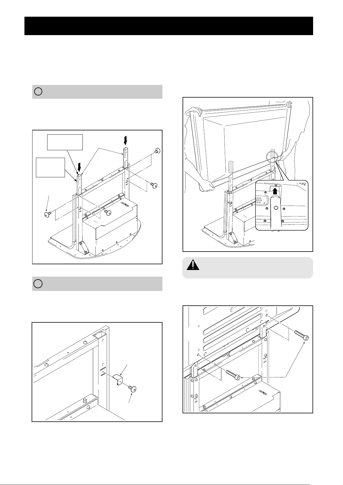
裝配步驟(圖示為43型)
1 將支柱安裝在主體上
因安裝的等離子顯示器的機種、式樣不同,安裝步驟
也不同。請從 A 、 B 中選擇合適的安裝方法,再進
行安裝。
A 在等離子顯示器兩側安裝揚聲器時
請將支柱插入主體,用螺絲(M5 × 10mm)進行固定。
貼有 ’ 標籤的一面是支柱的正面,附有樹脂端蓋的部分
(頂部較細)是支柱的頂部。
附有端蓋的部分
是支柱的頂部
貼有’標籤
的一面是支
柱的正面
螺絲
(M5 × 10mm)
支柱
2 將等離子顯示器安裝在支柱上
請將等離子顯示器下部中央的凹部對準立架的支柱,慢慢
垂直插入。請注意不要使立架的支柱碰到等離子顯示器的
支架插入口以外的部分。否則有可能使主體背面或端子劃
傷、變形。如果等離子顯示器帶有把手,抓住把手可以方
便操作。
B 在等離子顯示器下部安裝揚聲器時
將支柱固定片裝入主體背面的凹口部,再用螺絲(M5 ×
10mm)固定(左右 2 處)。
支柱的安裝方法與 A 相同。
支柱固定片
如圖所示,將等離子顯示
器下部和支柱嵌合。
請務必由 2 個人以上進行安裝
警 告
請注意不要夾傷手指
3 用六角孔螺栓固定等離子顯示器和支柱(4 處)
六角孔螺栓
(M8 × 35mm)
40
Ch
螺絲(M5 × 10mm)
安裝揚聲器時,請在此步驟上進行安裝。
有關揚聲器的安裝步驟,請參照揚聲器附帶的說明書。
Page 41

裝配步驟
4 使用擱板時
本設備也可以安裝擱板。
1 卸下擱板蓋,將擱板支承架 L、 R卡在主體上再進行安
裝。
擱板蓋
擱板支承架 R
按入式鉚釘
擱板支承架 L
按入式
鉚釘
按入
5 豎向安裝多媒體接收器時
將安裝在豎向安裝用立架上的多媒體接收器(有關安裝方
法,請參照等離子顯示器的操作說明書)放置在後側的擱板
上,再用 MR 支架配件的前板和後板固定豎向安裝用立架。
注 意
請不要在此位置上安裝多媒體接收器以外的設備。
MR 立架
配件前板
多媒體接收器
MR 立架
配件後板
2 將擱板從後部插入,用按入式鉚釘進行固定。
擱板安裝時可以選擇前部或後部 2 處位置。
請按照您擁有的設備型號進行設定。
需要變更位置時,祇要將按入式鉚釘上部的旋鈕拉
出就可以簡單地拆卸了。
擱板開口處內部尺寸:420 (有效寬度) [開口 436]
× 102(高)mm
擱板深度:349mm
耐負載:最大 10kg
注 意
在此板上裝載多媒體接收器以外(特別是 AV 放大器)的設
備時,因為有可能產生阻礙散熱等情況,請充分注意。
有關詳細說明﹐請參照各設備的操作說明書。
前部位置用孔
後部位置用孔
擱板
6 安裝底座護板 L 、 R 及後蓋
請沿著底座部分嵌入。
基座護蓋 L
基座護蓋 R
中國語
可動
位置
鎖定
位置
前面側
按入式鉚釘
前部位置
基座護蓋後蓋
後部位置
41
Ch
Page 42
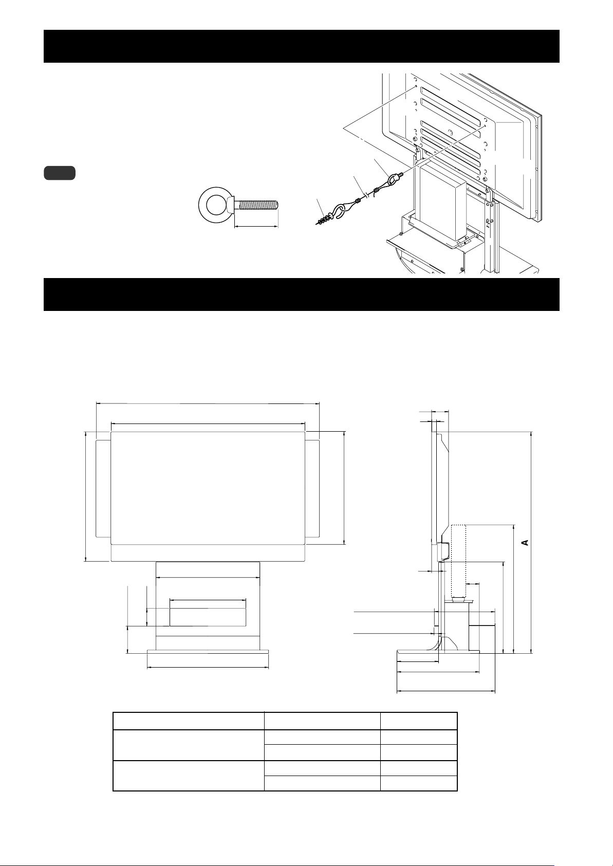
防止傾倒(在設置完畢後必須採取防止傾倒的措施。)
(
型)
1 安裝防止電漿顯示器傾倒用的螺栓(拉鉤)
2 利用結實的繩類或鎖鏈將它牢牢地固定在柱
子、牆壁等堅實之處。
在左右對稱的 2 個部位進行同樣的作業。
注 意
拉鉤、繩類或鎖鏈、安裝器具請使用市
售品。
推薦拉鉤: 公稱直徑 8
長度12∼15毫米
外形尺寸圖
重量 19.5kg(僅立架)
52.8kg(立架+等離子顯示器〈安裝 PDP-434HD/PDP-4340HD/PDP-434HDE/PDP-434HDG/PRO-910HD 顯示器和揚聲器時〉)
61.0kg(立架+等離子顯示器〈安裝 PDP-504HD/PDP-5040HD/PDP-504HDE/PDP-504HDG/PRO-1110HD 顯示器和揚聲器時〉)
(單位:mm)
1440(50型)
1290(43型)
1270(50型)
1120(43型)
1 拉鉤
2 繩類或鎖鏈
安裝器具
12〜15mm
98
28
50
833
748(43型)
600
420 (有效寬度)
[開口 436]
開口 102
162(擱板上面)
701
等離子顯示器 安裝揚聲器
PDP-434HD/PDP-4340HD/PDP-434HDE/
PDP-434HDG/PRO-910HD
PDP-504HD/PDP-5040HD/PDP-504HDE/
PDP-504HDG/PRO-1110HD
737(50型)
652(43型)
等離子顯示器的兩旁
等離子顯示器的下方
等離子顯示器的兩旁
等離子顯示器的下方
41
349(擱板面)
70(擱板前部位置)
25(擱板內部位置)
240
517(擱板前部位置)
567(擱板內部位置)
全高(尺寸 A)
1,180
1,279
1,265
1,364
79
742
528
476
•上述規格以及外觀,因為改良之故可能會無事先通告而發生變動。
42
Ch
日本先鋒公司出版
版權©2003日本先鋒公司
版權所有
Page 43

Page 44
この取扱説明書は再生紙を使用しています。
Published by Pioneer Corporation.
2003パイオニア株式会社 禁無断転載
Copyright © 2003 Pioneer Corporation.
All rights reserved.
〒153-8654 東京都目黒区目黒1丁目4番1号
PIONEER CORPORATION 4-1, Meguro 1-Chome, Meguro-ku, Tokyo 153-8654, Japan
PIONEER ELECTRONICS (USA) INC. P.O.BOX 1540, Long Beach, California 90801-1540, U.S.A., TEL: 1-310-952-2111
PIONEER EUROPE NV MULTIMEDIA DIVISION
PIONEER ELECTRONICS AUSTRALIA PTY.LTD. 178-184 Boundary Road, Braeside, Victoria 3195, Australia, TEL: 61-39-586-6300
PIONEER ELECTRONICS ASIACENTRE PTE. LTD. 253 Alexandra Road #04-01, Singapore 159936, TEL: 65-6472-1111
PIONEER HIGH FIDELITY TAIWAN CO., LTD.
PIONEER ELECTRONICS (CHINA) LTD. Room 1704-06, 17/F World Trade Centre, 280 Gloucester Rd. Causeway Bay, Hong Kong, TEL: 852-2848-6488
PIONEER GULF FZE Lob 11-017, Jebel Ali Free Zone P.O. BOX 61226, Jebel Ali, Dubai, United Arab Emirates, TEL: 971- 4-8815756
PIONEER ELECTRONICS DE MEXICO S.A. DE C.V. Blvd. Manuel Avila Camacho 138 10 piso Col.Lomas de Chapultepec, Mexico, D.F. 11000 TEL: 55-9178-4270
Pioneer House Hollybush Hill, Stoke Poges, Slough SL2 4QP, U.K., TEL: 44-1753-789-789
13FL., No44 Chung Shan North Road, Sec.2. Taipei, Taiwan, TEL: 886-2-2521-3588
Printed in Japan / Imprimé au Japon <AZR1073-A>
 Loading...