

PIONEER KEH-P424, KEH-P4700, KEH-P4750 Service Manual
PIONEER ELECTRONIC CORPORATION 4-1, Meguro 1-Chome, Meguro-ku, Tokyo 153-8654, Japan
PIONEER ELECTRONICS SERVICE INC. P.O.Box 1760, Long Beach, CA 90801-1760 U.S.A.
PIONEER ELECTRONIC [EUROPE] N.V. Haven 1087 Keetberglaan 1, 9120 Melsele, Belgium
PIONEER ELECTRONICS ASIACENTRE PTE.LTD. 501 Orchard Road, #10-00, Wheelock Place, Singapore 238880
C PIONEER ELECTRONIC CORPORATION 1998
K-ZEM. FEB. 1998 Printed in Japan
ORDER NO.
CRT2169
MULTI-CD CONTROL HIGH POWER CASSETTE PLAYER WITH FM/AM TUNER
Se
r
vic
e
M
a
nu
a
l
KEH-P424 X1M/UC
NOTE:
- See the separate manual CX-631(CRT1640) for the cassette mechanism description.
- The cassette mechanism assy employed in this model is one of 2L series.
- Dolby noise reduction manufactured under license from Dolby Laboratories Licensing Corporation.
"Dolby" and the double-D symbol are trademarks of Dolby Laboratories Licensing Corporation.
- This service manual does not describe the CD test mode.
For the operations in the CD test mode, refer to the CD player's Service Manual.
KEH-P4700 X1M/UC
• KEH-P424/X1M/UC
CONTENTS
1. SAFETY INFORMATION ...........................................2
2. EXPLODED VIEWS AND PARTS LIST......................2
3. SCHEMATIC DIAGRAM ............................................8
4. PCB CONNECTION DIAGRAM ...............................18
5. ELECTRICAL PARTS LIST .......................................28
6. ADJUSTMENT ........................................................35
7. GENERAL INFORMATION ......................................37
7.1 PARTS.................................................................37
7.1.1 IC...............................................................37
7.1.2 DISPLAY ...................................................41
7.2 DISASSEMBLY ..................................................42
7.3 BLOCK DIAGRAM..............................................43
8. OPERATIONS AND SPECIFICATIONS ...................44
KEH-P4750 X1M/ES

2. EXPLODED VIEWS AND PARTS LIST
2.1 PACKING
2
KEH-P424,P4700,P4750
5
10
16
4
15
14
13
12
9
6
8
11
7
22
3
2
1
17,18,19,
20,21
Fig. 1
1. SAFETY INFORMATION
UC model
CAUTION
This service manual is intended for qualified service technicians; it is not meant for the casual do-it-yourselfer.
Qualified technicians have the necessary test equipment and tools, and have been trained to properly and safely repair
complex products such as those covered by this manual.
Improperly performed repairs can adversely affect the safety and reliability of the product and may void the warranty.
If you are not qualified to perform the repair of this product properly and safely, you should mot risk trying to do so
and refer the repair to a qualified service technician.
W
ARNING
Lead in solder used in this product is listed by the California Health and Welfare agency as a known reproductive
toxicant which may cause birth defects or other reproductive harm (California Health and Safety Code, Section
25249.5). When servicing or handling circuit boards and other components which contain lead in solder, avoid
unprotected skin contact with the solder. Also, when soldering do not inhale any smoke or fumes produced.
3
KEH-P424,P4700,P4750
NOTE:
- Parts marked by “*”and ⊗ can not be supplied.
- Screws adjacent to ∇ mark on the product are used for disassembly.
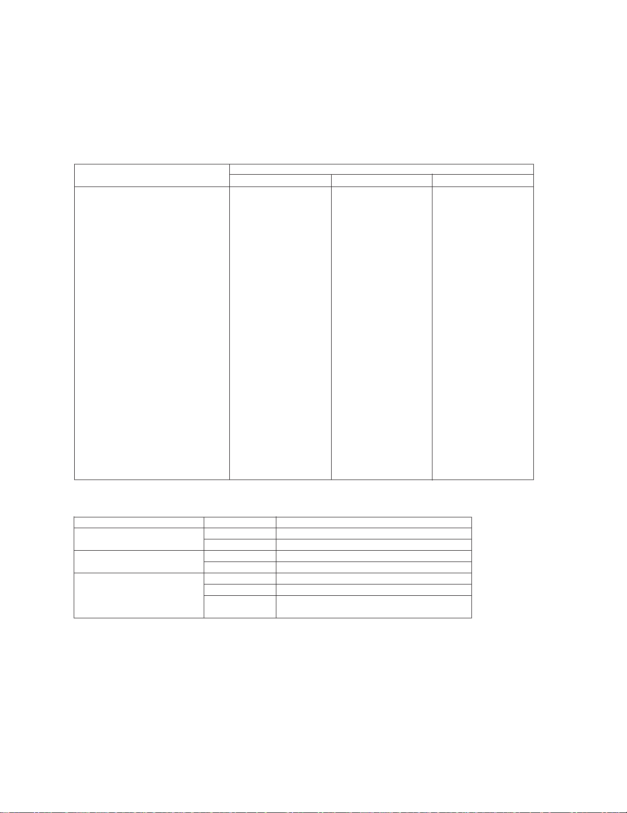
- PACKING SECTION PARTS LIST
Part No.
Mark No. Description KEH-P424/X1M/UC KEH-P4700/X1M/UC KEH-P4750/X1M/ES
1 Cord Assy CDE5496 CDE5496 CDE5496
* 2 Accessory Assy CEA2350 CEA2350 CEA2350
3 Spring CBH1650 CBH1650 CBH1650
4 Screw Assy CEA2351 CEA2351 CEA2351
5 Screw CBA1304 CBA1304 CBA1304
* 6 Polyethylene Bag CEG-127 CEG-127 CEG-127
7 Screw(x4) CRZ50P090FMC CRZ50P090FMC CRZ50P090FMC
8 Screw(x4) TRZ50P080FMC TRZ50P080FMC TRZ50P080FMC
* 9 Polyethylene Bag CEG-158 CEG-158 CEG-158
10 Handle(x2) CNC5395 CNC5395 CNC5395
11 Bush CNV3930 CNV3930 CNV3930
12 Polyethylene Bag CEG1173 CEG1173 CEG1-162
13 Carton CHG3471 CHG3470 CHG3472
14 Contain Box CHL3471 CHL3470 CHL3472
15 Protector CHP2021 CHP2021 CHP2021
16 Protector CHP2022 CHP2022 CHP2022
17 Owner’s Manual CRD2585 CRD2587 CRD2596
18 Installation Manual CRD2586 CRD2588 CRD2598
* 19 Warranty Card CRY1070 Not used Not used
* 20 Card Not used ARY1048 Not used
21 Owner’s Manual Not used Not used CRD2597
22 Case Assy CXB1063 CXB1063 CXB1063
- Owner's Manual, Installation Manual
Model Part No. Language
KEH-P424/X1M/UC CRD2585 English, French
CRD2586 English, French
KEH-P4700/X1M/UC CRD2587 English, French, Spanish
CRD2588 English, French, Spanish
KEH-P4750/X1M/ES CRD2596 English, Spanish, Portuguese
CRD2597 Chinese, Arabic
CRD2598 English, Spanish,
Portuguese, Chinese, Arabic

4
KEH-P424,P4700,P4750
Fig. 2
2.2 EXTERIOR

5
KEH-P424,P4700,P4750
(1) EXTERIOR SECTION PARTS LIST
Mark No. Description Part No.
Mark No. Description Part No.
1 Screw BSZ26P050FMC
2 Screw BSZ30P060FMC
3 Cord Assy CDE5496
4 Spring CBH1650
5 Screw CBA1304
6 Handle CNC5395
7 Bush CNV3930
8 Fuse CEK1136
9 Case CNB2283
10 Holder CNC6798
11 Panel CNS4200
12 Screw BMZ30P100FMC
13 Screw BSZ30P055FUC
14 Screw BSZ30P060FMC
15 Holder Unit CXB2687
16 Cushion CNM4870
17 Insulator CNM5571
⊗ 18 Tuner Amp Unit
See Contrast table(2)
19 Screw BPZ26P080FMC
20 Screw BSZ26P080FMC
21 Screw BSZ26P140FMC
22 Cord Assy(CN603)
See Contrast table(2)
23 FM/AM Tuner Unit See Contrast table(2)
24 Holder CNC6554
25 Pin Jack(CN301) CKB1028
26 Plug(CN951) CKM1270
27 Connector(CN751) CKS3408
28 Connector(CN602) CKS3568
29 Connector(CN601) CKS3581
30 Antenna Jack(CN402) CKX1056
31 Panel CNB2256
32 Holder CNC5399
33 Holder CNC6531
34 Holder CNC6674
35 Holder CNC6845
36 Heat Sink CNR1426
37 Chassis Unit CXB2347
38 Case Assy CXB1063
39 Button CAC4836
40 Spring CBH1834
41 Spring CBH1835
42 Spring CBH1996
43 Bracket CNC6135
44 Bracket CNC6791
45 Arm CNV4692
46 Arm CNV4693
47 Arm CNV4728
48 Panel Unit
See Contrast table(2)
49 Door CAT1947
50 Spring CBH1838
51 Screw IMS20P030FZK
52 Detach Grille Assy
See Contrast table(2)
53 Screw BPZ20P100FZK
54 Button( ) CAC5430
55 Button( , ) CAC5431
56 Button(SOURCE) CAC5433
57 Button(+,–) CAC5435
58 Button(BAND,F,A) CAC5437
59 Button(1,2,3,4,5,6) CAC5439
60 Button(D) CAC5441
61 Button(LD/CLK,P, ) CAC5542
62 Spring CBH2103
63 Spacer CNM5572
64 Sheet CNM5897
65 Cover CNS4775
66 Lighting Conductor CNV5195
67 Keyboard Unit CWM5801
68 LCD(LCD901) CAW1477
69 Connector(CN901) CKS3580
70 Holder CNC7479
71 Sheet CNM5726
72 Sheet CNM5727
73 Sheet CNM5728
74 Lighting Conductor CNV5196
75 Housing CNV5197
76 Connector CNV5205
77 Grille Unit
See Contrast table(2)
78 Cassette Mechanism Module EXK3615
79 Transistor(Q951) 2SD2396
80 IC(IC301)
See Contrast table(2)
81 LED(D903 — 905) NSPWF50SB
,
,

6
KEH-P424,P4700,P4750
2.3 CASSETTE MECHANISM MODULE
Part No.
Mark No. Symbol and Description KEH-P424/X1M/UC KEH-P4700/X1M/UC KEH-P4750/X1M/ES
⊗ 18 Tuner Amp Unit CWM5847 CWM5836 CWM5800
22 Cord Assy(CN603) CDE5178 Not used Not used
23 FM/AM Tuner Unit CWE1467 CWE1467 CWE1486
48 Panel Unit CXB2352 CXB2367 CXB2367
52 Detach Grille Assy CXB2446 CXB2442 CXB2308
77 Grille Unit CXB2491 CXB2490 CXB2492
80 IC(IC301) TDA7386 TDA7384 TDA7384
(2) CONTRAST TABLE
KEH-P424/X1M/UC, KEH-P4700/X1M/UC and KEH-P4750/X1M/ES are constructed the same except for
the following:
Fig. 3

7
KEH-P424,P4700,P4750
1 Screw BSZ20P040FMC
2 Washer CBF1037
3 Washer CBF1038
4 Washer CBG1003
5 Deck Unit EWM1010
6 Screw EBA1028
7 Screw EBA1037
8 Spring EBH1531
9 Spring EBH1575
10 Plug(CN251) CKS3540
11 Spring EBH1515
12 Spring EBH1587
13 Spring EBH1517
14 Spring EBH1518
15 Spring EBH1519
16 Spring EBH1537
17 Cord EDD1020
18 Photo-interrupter
(EGN2,3) EGN1006
19 Photo-interrupter(EGN1) EGN1005
20 Roller ENR1031
21 Shaft ELA1373
22 Pinch Roller ENV1518
23 Arm ENC1489
24 Arm ENC1397
25 Guide ENC1481
26 Holder ENC1417
27 Lever ENC1448
28 Arm ENC1488
* 29 Motor EXM1031
30 Belt ENT1027
31 Gear ENV1347
32 Collar ENV1508
33 Gear ENV1350
34 Flywheel ENV1529
35 Worm Gear ENV1439
36 Worm Wheel ENV1440
37 Gear ENR1028
38 Lever ENV1442
39 Arm ENV1525
40 Gathering P.C.Board ENX1037
41 Gathering P.C.Board ENX1042
42 Switch(S1,S2) ESG1004
43 Motor Unit(M2) EXA1485
44 Chassis Unit EXA1511
45 Pinch Holder ENV1485
46 Pinch Holder ENV1486
47 Reel Unit EXA1543
48 Head Base Unit EXA1457
49 Lever Unit EXA1438
50 Gear Unit EXA1545
51 Frame Unit EXA1458
52 Lever Unit EXA1439
53 Head Assy(HD1) EXA1506
54 Motor Unit(M1) EXA1544
55 Washer HBF-179
56 Screw BMZ20P022FMC
57 Spring EBH1545
58 Washer YE20FUC
59 Pinch Holder Unit EXA1529
60 Pinch Holder Unit EXA1528
Mark No. Description Part No. Mark No. Description Part No.
- CASSETTE MECHANISM MODULE SECTION PARTS LIST
8
KEH-P424,P4700,P4750
A
1
234
B
C
D
12
34
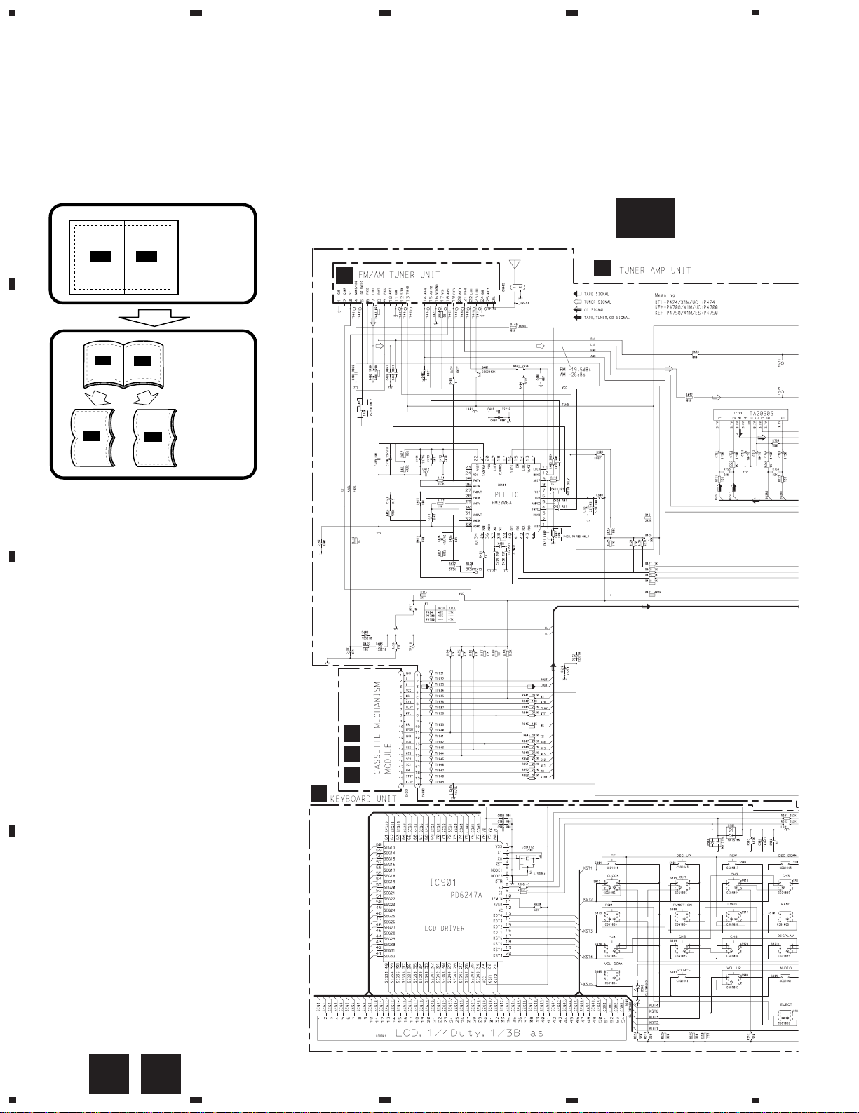
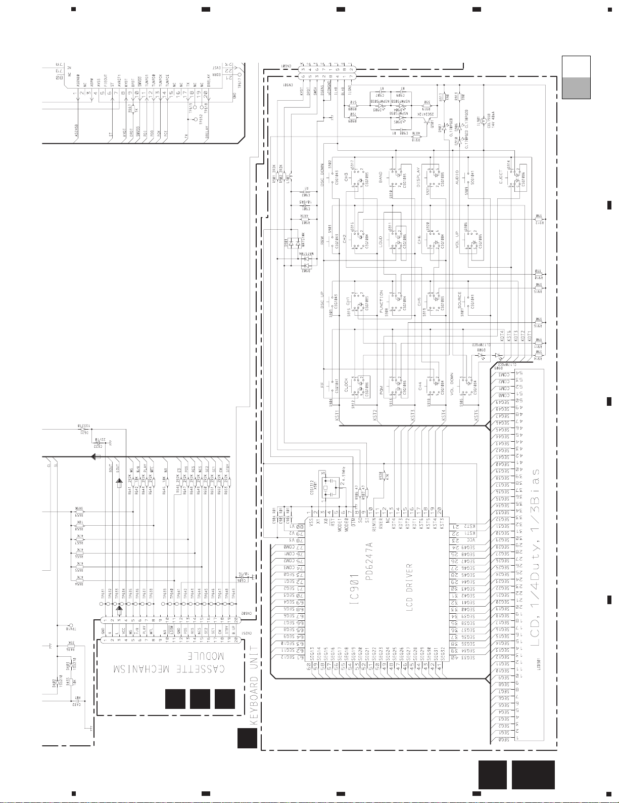
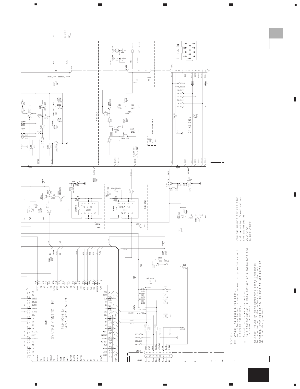
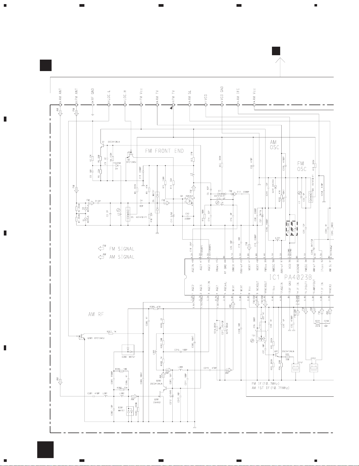
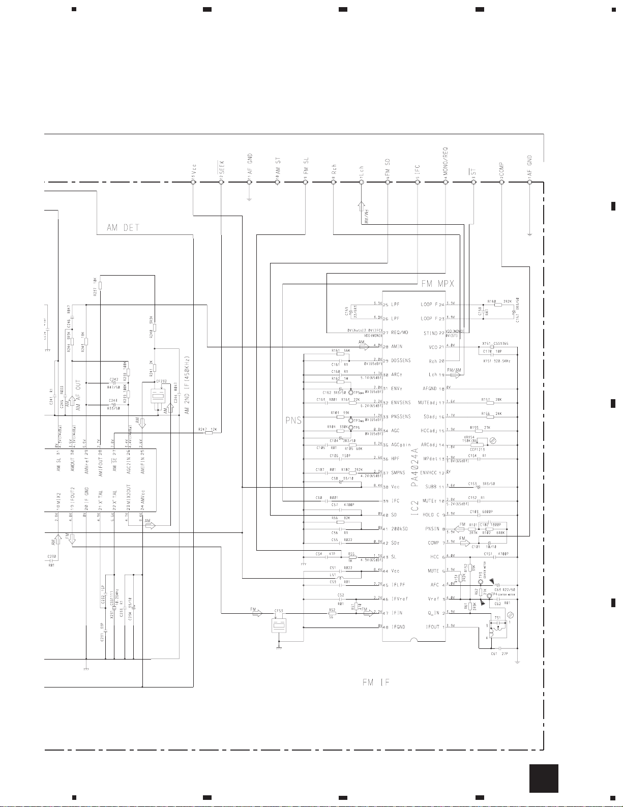
3. SCHEMATIC DIAGRAM
3.1 OVERALL CONNECTION DIAGRAM (GUIDE PAGE)
Note: When ordering service parts, be sure to refer to “EXPLODED VIEWS AND PARTS LIST” or “ELECTRICAL
PARTS LIST”.
A-a A-b
A-a
A-b
A-b
A-a
Large size
SCH diagram
Guide page
Detailed page
A
C
A-a
A
B
C
D
E
F

9
KEH-P424,P4700,P4750
5
6
7
8
A
B
C
D
5
6
7
8
A-b
A
Fig. 4
POWER AMP
10
KEH-P424,P4700,P4750
A
1
234
B
C
D
12
34
A
B
A-a
A-a
A-b
11
KEH-P424,P4700,P4750
5
6
7
8
A
B
C
D
5
6
7
8
C
D
E
F
Fig. 5
A-a
A-a
A-b
C

12
KEH-P424,P4700,P4750
A
1
234
B
C
D
12
34
POWER AMP
A-a
A-b
A-b
13
KEH-P424,P4700,P4750
5
6
7
8
A
B
C
D
5
6
7
8
Fig. 6
A-b
A-a
A-b
14
KEH-P424,P4700,P4750
A
1
234
B
C
D
12
34
KEH-P424/X1M/UC
P4700/X1M/UC
KEH-P4750/X1M/ES
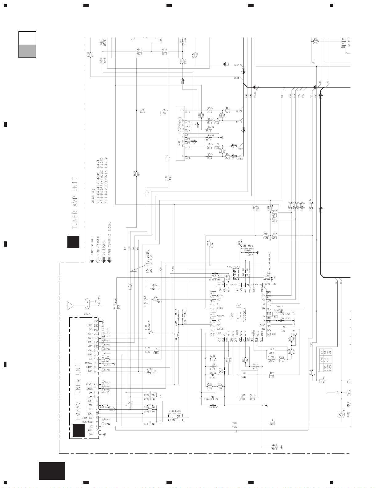
3.2 FM/AM TUNER UNIT
B
A
B
FM/AM TUNER UNIT
15
KEH-P424,P4700,P4750
5
6
7
8
A
B
C
D
5
6
7
8
B
Fig. 7
 Loading...