

Pioneer KEH-P3086ZY Service Manual
PIONEER ELECTRONIC CORPORATION 4-1, Meguro 1-Chome, Meguro-ku, Tokyo 153-8654, Japan
PIONEER ELECTRONICS SERVICE INC. P.O.Box 1760, Long Beach, CA 90801-1760 U.S.A.
PIONEER ELECTRONIC [EUROPE] N.V. Haven 1087 Keetberglaan 1, 9120 Melsele, Belgium
PIONEER ELECTRONICS ASIACENTRE PTE.LTD. 501 Orchard Road, #10-00, Wheelock Place, Singapore 238880
C PIONEER ELECTRONIC CORPORATION 1998
K-ZED. JAN.1998 Printed in Japan
ORDER NO.
CRT2162
AM/FM CASSETTE DECK
Se
r
vic
e
M
a
nu
a
l
KEH-P3086ZY X1INES
DAIHATSU
CONTENTS
1. SAFETY INFORMATION ............................................2
2. EXPLODED VIEWS AND PARTS LIST.......................2
3. SCHEMATIC DIAGRAM .............................................6
4. PCB CONNECTION DIAGRAM ................................16
5. ELECTRICAL PARTS LIST ........................................26
6. ADJUSTMENT..........................................................32
7. GENERAL INFORMATION .......................................34
7.1 PARTS .................................................................34
7.1.1 IC ................................................................34
7.1.2 DISPLAY.....................................................37
7.2 DIAGNOSIS ........................................................38
7.2.1 TEST MODE..............................................38
7.2.2 DISASSEMBLY .........................................39
7.2.3 CONNECTOR FUNCTION DESCRIPTION ..40
7.3 BLOCK DIAGRAM ..............................................41
8. OPERATIONS AND SPECIFICATIONS.....................42
NOTE:
- Dolby noise reduction manufactured under license from Dolby Laboratories Licensing Corporation.
"Dolby" and the double-D symbol are trademarks of Dolby Laboratories Licensing Corporation.
- See the separate manual CX-631(CRT1640) for the cassette mechanism description.
- The cassette mechanism module employed in this model is one of 2L series.
VEHICLE DESTINATION PRODUCED AFTER DAIHATSU PART No. ID No. PIONEER MODEL No.
Not specified INDONESIA January 1998 86120-87Z02 KEH-P3086ZY/X1INES

2
KEH-P3086ZY
1. SAFETY INFORMATION
This service manual is intended for qualified service technicians; it is not meant for the casual do-ityourselfer. Qualified technicians have the necessary test equipment and tools, and have been trained to
properly and safely repair complex products such as those covered by this manual.
Improperly performed repairs can adversely affect the safety and reliability of the product and may void
the warranty. If you are not qualified to perform the repair of this product properly and safely, you should
mot risk trying to do so and refer the repair to a qualified service technician.
Fig. 1
2. EXPLODED VIEWS AND PARTS LIST
2.1 EXTERIOR

3
KEH-P3086ZY
1 Screw BMZ26P050FMC
2 Screw BMZ26P150FMC
3 Screw BMZ30P050FMC
4 Screw BMZ30P080FZK
5 Case CNB2149
6 Earth Plate CNC7121
* 7 Cushion CNM5281
8 Insulator CNM5538
9 Heat Sink CNR1445
10 Amp Unit CWH1245
11 Connector(CN802) CKM1117
12 Connector(CN801) CKM1118
13 Connector(CN804) CKS2526
14 Connector(CN803) CKS2528
15 Holder CNC5767
16 Bracket CNC6957
17 Main Unit CWM5474
18 Screw BMZ30P050FMC
19 Tuner Unit CWE1426
20 Holder CNC6122
21 Terminal(CN501) CKF1059
22 Connector(CN602) CKS1730
23 Connector(CN104) CKS2516
24 Connector(CN103) CKS2518
25 Connector(CN101) CKS3410
26 Plug(CN102) CKS3536
* 27 Holder CNC6066
28 Holder CNC6211
29 Holder CNC7183
30 Screw BPZ20P080FMC
31 Button(MODE,MUTE) CAC5226
32 Button(CD,AM/FM,TAPE) CAC5227
33 Button(PWR) CAC5228
34 Button( ) CAC5229
35 Button(SC) CAC5230
36 Button( ) CAC5231
37 Button(1–3) CAC5232
38 Button(4–6) CAC5233
39 Button(TUN,MS) CAC5234
40 Cushion CNM5830
41 LCD(LCD901) CAW1452
42 Socket(CN902) CKS3549
43 Holder CNC7184
44 Conductor CNC7209
45 Conductor CNC7210
46 Plate CNM5191
47 Lighting Conductor CNV4991
48 Lighting Conductor CNV4992
49 Lighting Conductor CNV4993
50 Lighting Conductor CNV4994
51 Holder CNV4995
52 Grille Unit CXB1906-/IN
53 Door CAT1936
54 Spring CBH1712
55 Chassis Unit CXB1592
56
Cassette Mechanism Module EXK3315
57 Screw IMS30P050FMC
58 IC(IC801) TDA7384
59 IC(IC451) PA2024A
60 Antenna Jack(AJ551) CKX1006
61 Owner's Manual CRD2724
(Indonesian)
- EXTERIOR SECTION PARTS LIST
Mark No. Description Part No.
Mark No. Description Part No.
NOTE:
- Parts marked by “*”are generally unavailable because they are not in our Master Spare Parts List.
- Screws adjacent to ∇ mark on the product are used for disassembly.

4
KEH-P3086ZY
2.2 CASSETTE MECHANISM MODULE
Fig. 2

5
KEH-P3086ZY
1 Screw BSZ20P040FMC
2 Washer CBF1037
3 Washer CBF1038
4 Washer CBG1003
5 Deck Unit EWM1007
6 Screw EBA1028
7 Screw EBA1037
8 Spring EBH1531
9 Spring EBH1575
10 Cushion ENM1034
11 Spring EBH1515
12 Spring EBH1587
13 Spring EBH1517
14 Spring EBH1518
15 Spring EBH1519
16 Spring EBH1537
17 Cord EDD1015
18
Photo-interrupter(EGN2,3) EGN1006
19 Photo-interrupter(EGN1) EGN1005
20 Roller ENR1031
21 Shaft ELA1373
22 Pinch Roller ENV1518
23 Arm ENC1396
24 Arm ENC1397
25 Guide ENC1398
26 Holder ENC1417
27 Lever ENC1448
28 Arm ENC1401
29 Motor EXM1027
30 Belt ENT1027
31 Gear ENV1347
32 Collar ENV1508
33 Gear ENV1350
34 Flywheel ENV1410
35 Worm Gear ENV1439
36 Worm Wheel ENV1440
37 Gear ENR1028
38 Lever ENV1442
39 Arm ENV1445
40 Gathering PCB ENX1037
41 PCB ENP1152
42 Switch(S1,S2) ESG1004
43 Motor Unit(M2) EXA1485
44 Chassis Unit EXA1511
45 Pinch Holder ENV1485
46 Pinch Holder ENV1486
47 Reel Unit EXA1456
48 Head Base Unit EXA1457
49 Lever Unit EXA1438
50 Gear Unit EXA1436
51 Frame Unit EXA1458
52 Lever Unit EXA1439
53 Head Assy(HD1) EXA1452
54 Motor Unit(M1) EXA1454
55 Washer HBF-179
56 Screw BMZ20P022FMC
57 Spring EBH1545
58 Washer YE20FUC
59 Pinch Holder Unit EXA1529
60 Pinch Holder Unit EXA1528
61 Resistor(R1) RD1/4PM181J
62 Connector(CN253) CKS2129
63 Connector(CN251) CKS1711
64 Connector(CN252) CKS2127
65 Spare Unit EXA3028
Mark No. Description Part No. Mark No. Description Part No.
- CASSETTE MECHANISM MODULE SECTION PARTS LIST

6
KEH-P3086ZY
A
1
234
B
C
D
12
34
3. SCHEMATIC DIAGRAM
3.1 OVERALL CONNECTION DIAGRAM(GUIDE PAGE)
Note: When ordering service parts, be sure to refer to “EXPLODED VIEWS AND PARTS LIST” or “ELECTRICAL PARTS
LIST”.
A-a A-b
A-aA-a
A-b A-b
A-b A-b
A-a A-a
Large size
SCH diagram
Guide page
Detailed page
A
A-a
14V 40mA
14V 40mA
14V 40mA
14V 40mA
8V 60mA
EL
ANTENNA JACK
D

7
KEH-P3086ZY
5
6
7
8
A
B
C
D
5
6
7
8
Fig. 3
A-b
C
A
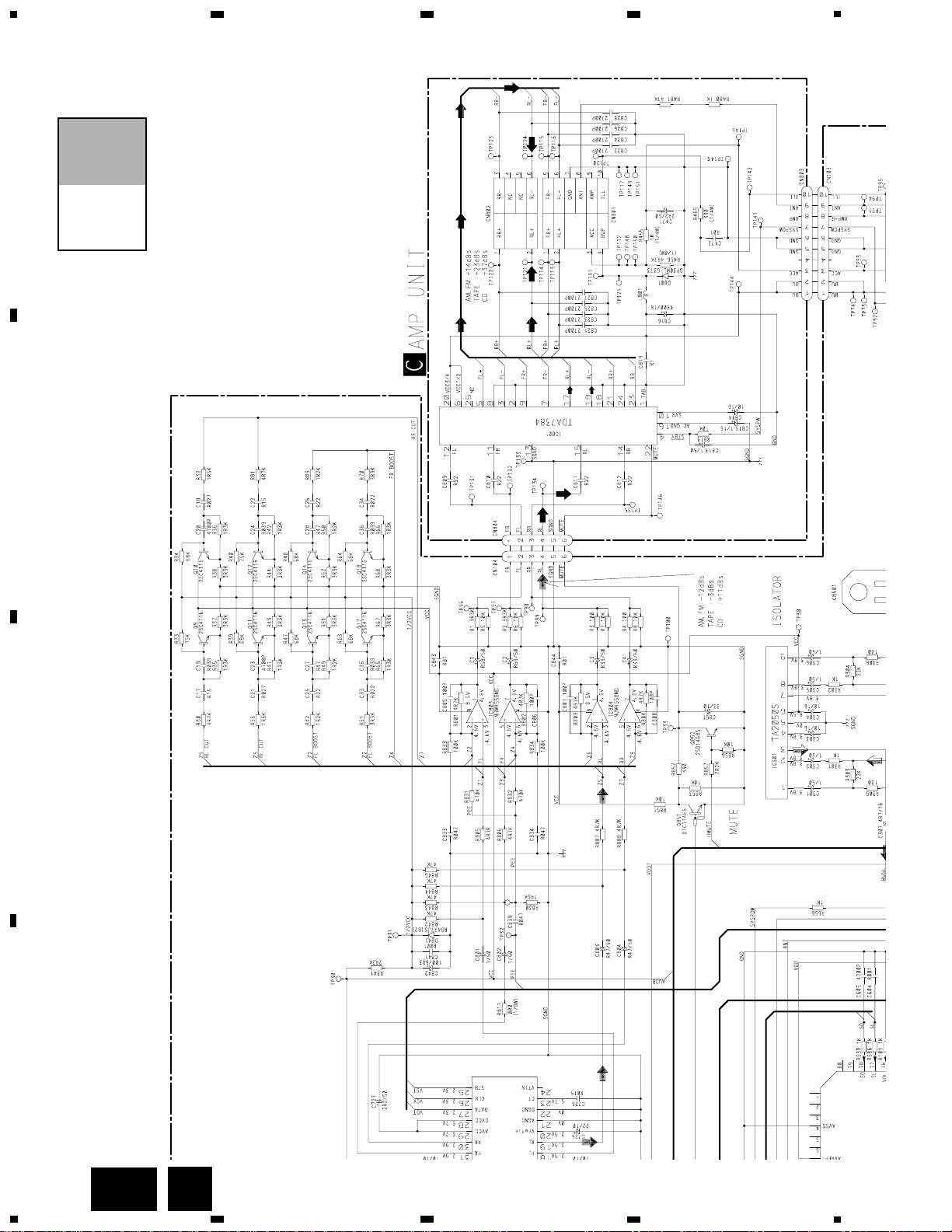
POWER AMP
SYSTEM CONTROLLER
FIX EQUALIZER

8
KEH-P3086ZY
A
1
234
B
C
D
12
34
A-a
A-a
A-b
ELECTRONIC VOLUME
ANTENNA JACK
D

9
KEH-P3086ZY
5
6
7
8
A
B
C
D
5
6
7
8
A-a
A-a
A-b
14V 40mA
14V 40mA
14V 40mA
14V 40mA
8V 60mA
SYSTEM CONTROLLER
Fig. 4
10
KEH-P3086ZY
A
1
234
B
C
D
12
34
POWER AMP
FIX EQUALIZER
A-b
A-a
A-b
C

11
KEH-P3086ZY
5
6
7
8
A
B
C
D
5
6
7
8
Fig. 5
A-b
A-a
A-b
12
KEH-P3086ZY
A
1
234
B
C
D
12
34
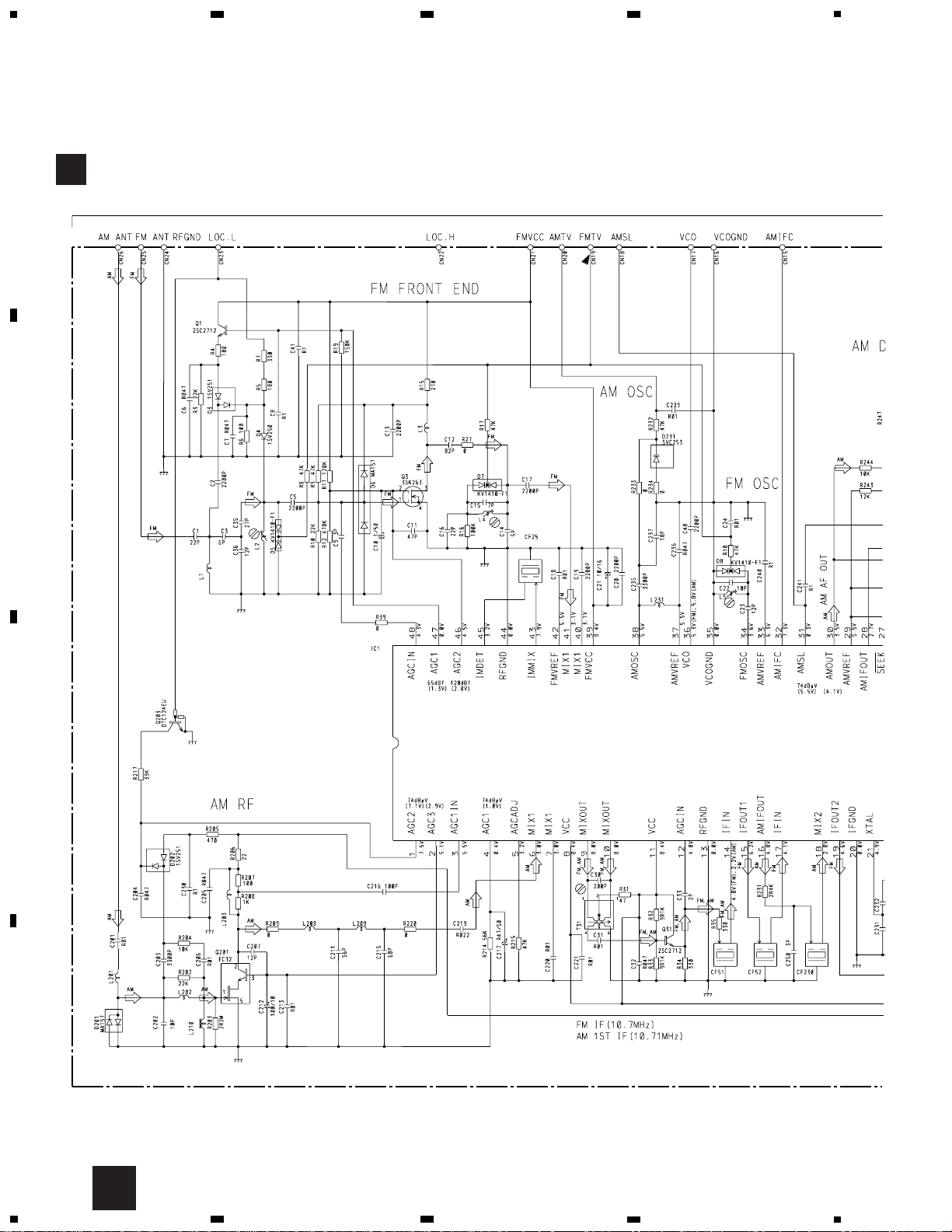
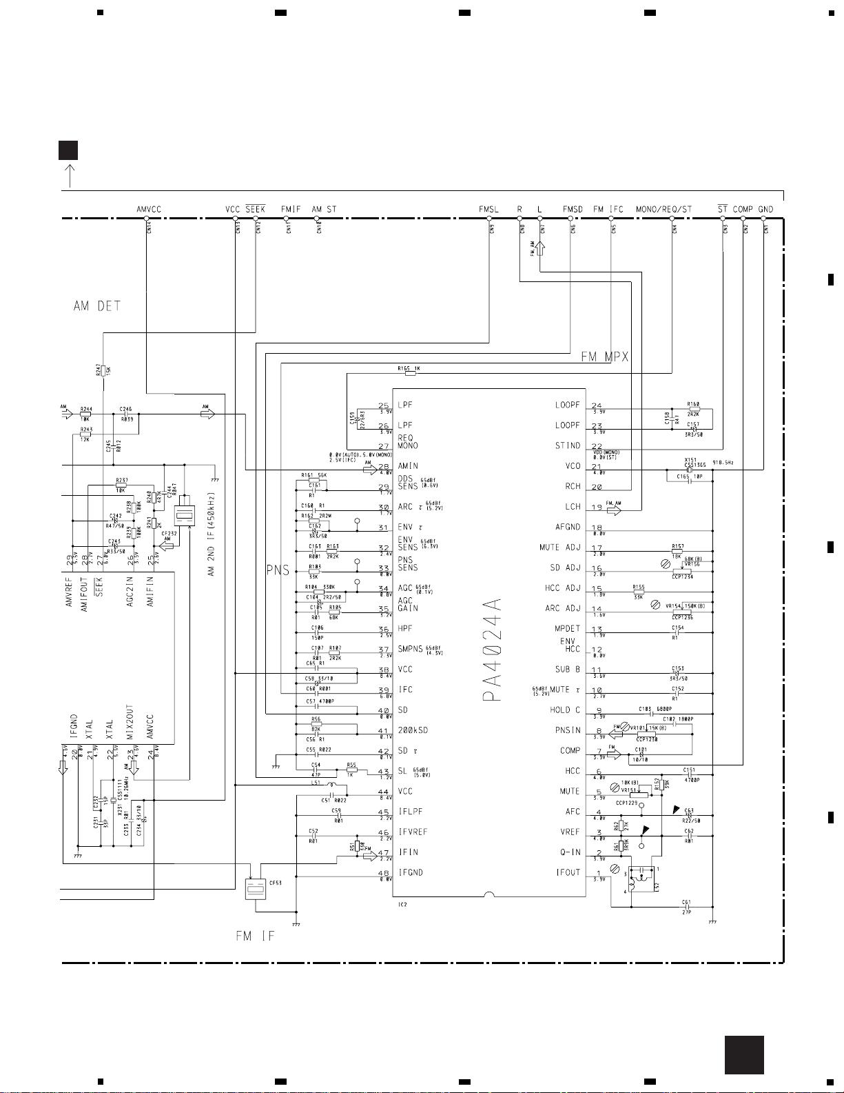
3.2 TUNER UNIT
PA4023B
TUNER UNIT
B
B
13
KEH-P3086ZY
5
6
7
8
A
B
C
D
5
6
7
8
A
Fig. 6
B
 Loading...