

Page 1
~i~
m
::l
CQ
t/)
::::r
BRIDGEABLE
AMPLIFICATEUR
AMPLIFICADOR
FOUR-CHANNEL
DE PUISSANCE
DE POTENCIA DE CUATRO
POWER AMPLIFIER
GM-6500F
PONTABLE A QUATRE
CANALES
EN
VOlES
PUENTE
m
t/)
"C
Dl
::lt
0
Owner's
Manual
de
Manual
Mode
d'emploi
instrucciones
Page 2
Section
ID
( Before you start
Thank
this PIONEER product.
To
ensure proper use, please read
manual
cially
WARNINGs
Please keep the
place (or future reference.
Information
Alteration or modifications carried out without
appropriate authorization may invalidate the
user's right to operate the equipment.
you
before using
important
and
for
purchasing
this
product. It is espe-
that
you read and observe
CAUTIONs
manual
in a safe
[!]
to
User
through
in
this
and
manual.
accessible
this
Visit
Visit us at the
http://www.pioneerelectronics.com
in Canada
http://www.pioneerelectronics.ca
1 Register your product.
2 Receive updates
3 Download owner's manuals, order product
The
our
of your purchase
this information
claim such
technologies.
catalogues, research new products, and
much
Safety
website
following
as
more.[!]
site:
We
will
keep
on
file to help
in
the event
loss or theft.
on
the latest products and
of
Your Ears
of
the details
you
refer to
an
insurance
is
Your Hands
)
in
After-sales service
Pioneer products
Please
where you purchased
service
other
mation
companies
Please do
at
advance contact.
U.S.A.
Pioneer Electronics
CUSTOMER
PO.
Long
800-421-1404
CANADA
Pioneer Electronics of Canada, Inc.
CUSTOMER
340
Unit 2
Markham, Ontario
1-877-283-5901
905-4 7 9-4411
For warranty
ited Warranty sheet included
contact
(including
information.
is not available, please
the
addresses listed below
Box
Beach,
Ferrier Street
the
warranty conditions)
In
listed below:
not
ship
SUPPORT
1760
CA
90801-1760
SATISFACTION
information
dealer
your
(USA)
L3R
or
distributor
this
unit
case the necessary infor-
unit
to the
for
Inc.
DIVISION
DEPARTMENT
2Z5,
Canada
please see
with
for
for
after-sales
contact
companies
repair
the
this
from
or
any
the
without
Lim-
unit.[!]
Get
the
most
out
of your
it at a safe
come
or
ing
out
affecting your sensitive hearing. Sound
can
be
"comfort
sound, so
be
loud and
against
safe level BEFORE your hearing adapts.
ESTABLISH A SAFE LEVEL:
• Set your
• Slowly increase the sound until you can
hear it
tortion.
• Once you have established a
sound level, set the dial and leave it there.
BE
SURE TO OBSERVE THE FOLLOWING
GUIDELINES:
• Do
can't
• Use
in potentially hazardous situations.
• Do
motorized vehicle; the use of headphones
may create a traffic hazard and is illegal in
many
level-a
through
distortion
deceiving.
this
not
hear
caution
not
clearly
and, most importantly, with-
Overtime,
level" adapts to
what
sounds
harmful
by
setting your
volume
comfortably
turn
up
the volume so high
what's
or
temporarily
use headphones while operating a
areas.[!]
equipment
level
that
lets the sound
without
"normal" can actually
to your hearing. Guard
control at a low setting.
and clearly,
around you.
annoying blar-
your hearing
higher
equipment
by
playing
volumes of
at a
without
comfortable
that
discontinue
dis-
you
use
mEn
Page 3
Section
st_a_rt
(_B_e_f_o_re_y~o_u
__
Before connecting/
installing
wARNING
A
• Handling
sociated with accessories
may expose
duct
proposition
and other
cer and birth defect or other reproductive
harm.
The use of a
•
wire
mended.
the car battery positive
ground wire to the car
This unit
•
negative grounding. Before installing
creational vehicles,
battery
• Always
The use of
overheating and smoke, damage to the
duct
• Check
and speakers if the fuse of the
battery wire or the
mine and
fuse with and
Do not
•
with
Also,
heating
The
speakers may
•
supply to the
equipment
the system power off and check the power
supply
able
your
• Always
the battery beforehand to avoid the risk of
electric
tion.
Wash
RD-223,
voltage.
use a fuse of the rating prescribed.
and injury,
the connections of the power
allow this unit to come into contact
liquids. Electrical shock
damage to this unit, smoke, and
surfaces of the
burns.
the event of any abnormality, the power
In
and speaker connections.
to determine the cause,
dealer.
disconnect the negative
the
the cord on this product or cords
you
known to the State of
65
governmental
hands after handling.
special
available separately,
Connect
for vehicles
is
an
resolve
could result
malfunction.
shock or short circuit during
the battery wire
improper fuse
including
amplifier
the cause, then
identical equivalent.
also heat up and cause
amplifier
_______________________________
cAUTION
A
amplifier
as-
with the
sold
chemicals listed
to
entities to cause
battery and ground
red
terminal
body.
with a
trucks or buses, check the
from contact with
amplifier
cut off to prevent
is
If
EB
V battery and
12
could result
burns.
separately sold
fuse blows. Deter-
could result.
and any attached
this occurs, switch
please
8
pro-
California
recom-
is
directly
and the
in
pro-
supply
replace
over-
liquids.
minor
are
you
If
contact
terminal
installa-
on
can-
to
re-
in
the
un-
of
• Always
outside sounds .
Extended use of the car stereo
•
gine
tery.
keep
at rest or
is
About the Protection function
Protection
The
outlined below.
tions
turned on, the power indicator
amplifier will
the
the speaker output
• If
wire is short-circuited.
• If the temperature inside the amplifier
high.
voltage
DC
a
• If
terminal.
put
Important (Serial
·
!)
:
serial number
The
your own security and convenience,
this unit.
be
warranty
For
sure to record this number
card.0
volume low
the
idling
function will operate
the
If
shut down.
applied
is
number)
located
is
enough
may exhaust the
Protection
will
terminal and speaker
to the speaker out-
the bottom of
on
the
on
to hear
en-
the
while
bat-
condi-
the
in
function is
turn off, and
gets too
enclosed
)GDI
m
::::»
'2.
c;r
::r
En
GJ
Page 4
Section
liD
(Setting
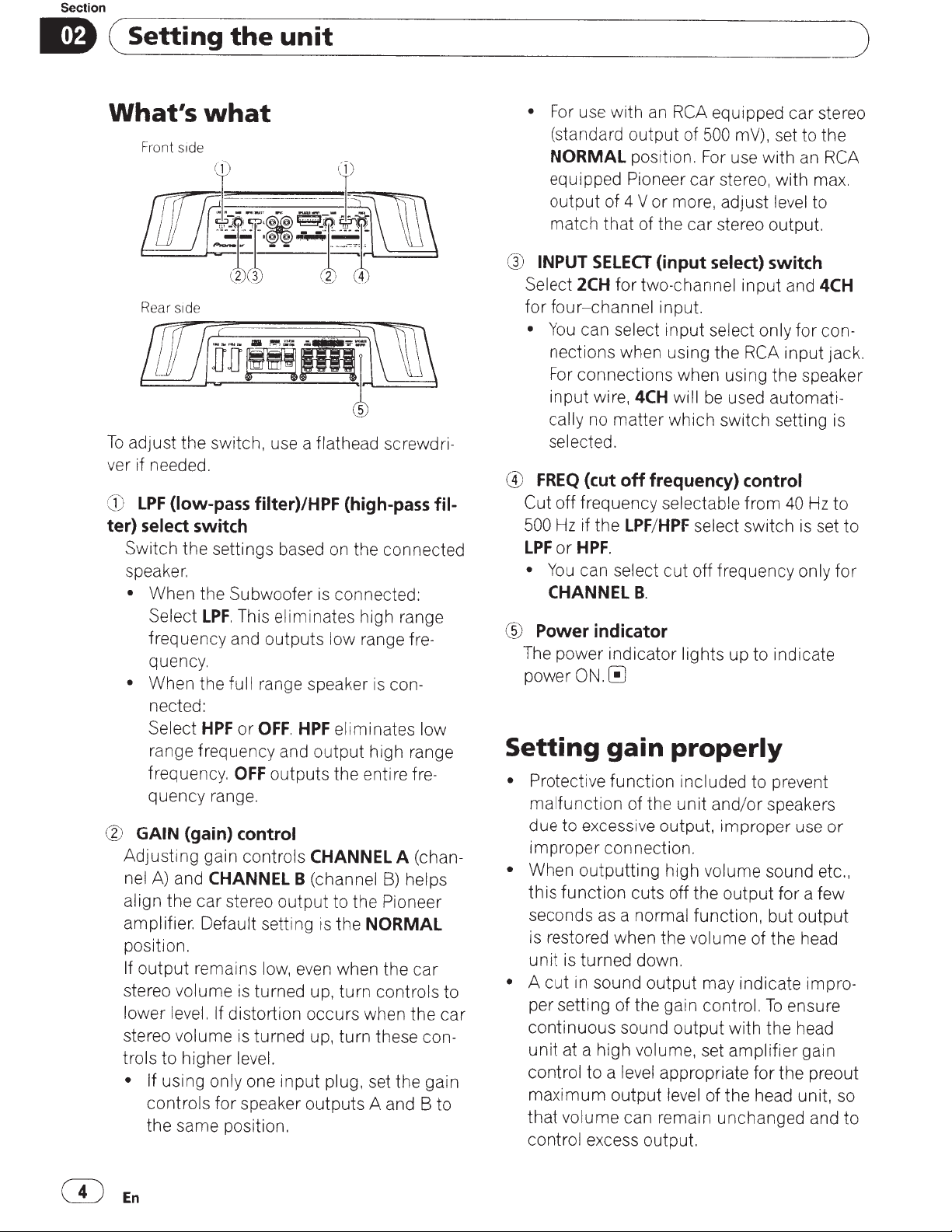
What's
Front side
ofi~~n
Rear side
To
adjust the switch, use a flathead
ver if needed.
G)
LPF
(low-pass filter)/HPF (high-pass fil-
ter)
select switch
Switch the settings based
speaker.
•
When the Subwoofer is connected:
Select
frequency and outputs low range
quency.
•
When the full range speaker
nected:
Select
range frequency and output high range
frequency.
quency range.
@
GAIN
Adjusting gain controls
nel
A)
and
align the car stereo output to the Pioneer
amplifier. Default setting
position.
If
output
stereo volume
lower level.
stereo volume
trols to higher level.
• If
using only one input plug, set the gain
controls for speaker outputs A and B to
the same position.
the
unit
what
( f )
(_2
\}
LPF.
This eliminates high range
HPF
or
OFF.
OFF
outputs the entire
(gain) control
CHANNEL
remains
If
low,
is
turned up, turn controls to
distortion occurs when the car
is
turned up, turn these
rT\
(
~
~
·
a;
on
the connected
HPF
eliminates low
CHANNEL
B
(channel
is
the
NORMAL
even when the car
screwdri-
fre-
is
con-
fre-
A
(chan-
B)
helps
con-
•
For
use with
(standard output of
NORMAL
equipped Pioneer car stereo, with max.
output of 4 V or more, adjust level to
match that of the car stereo output.
G)
@
®
The
INPUT
Select
for
•
FREQ
Cut
500
LPF
•
Power
power
SELECT
2CH
four-channel
Yo
u can select input select only for
nections when using the
For
connections when using the speaker
input wire,
cally no matter which switch setting is
selected.
(cut
off frequency selectable from
Hz
if the
or
HPF.
You
can select cut off frequency only for
CHANNEL
indicator
power indicator lights up to indicate
ON.[!]
Setting
• Protective function included to prevent
malfunction of the unit and/or speakers
due to excessive output, improper use
improper connection.
•
When outputting high volume sound etc.,
this function cuts off the output for a few
seconds
is restored when the volume of the head
unit is turned down.
•
A
cut
per setting of the gain control.
continuous sound output with the head
unit at a high volume, set amplifier gain
control to a level appropriate for the preout
maximum output level of the head unit,
that volume can remain unchanged and to
control excess output.
as
in sound output may indicate
an
RCA
equipped car stereo
500
position.
for two-channel input and
4CH
off
frequency) control
LPF
/
B.
gain
a normal function, but output
For
use with
(input
input.
HPF
select) switch
will
be
used
select switch
properly
mV), set to the
an
RCA
4CH
con-
RCA
input jack.
automati-
40
Hz
to
is
set to
or
impro-
To
ensure
so
CD
En
Page 5
Section
~~s_e_-tt_i_n_g_t_h_e_u_n_it
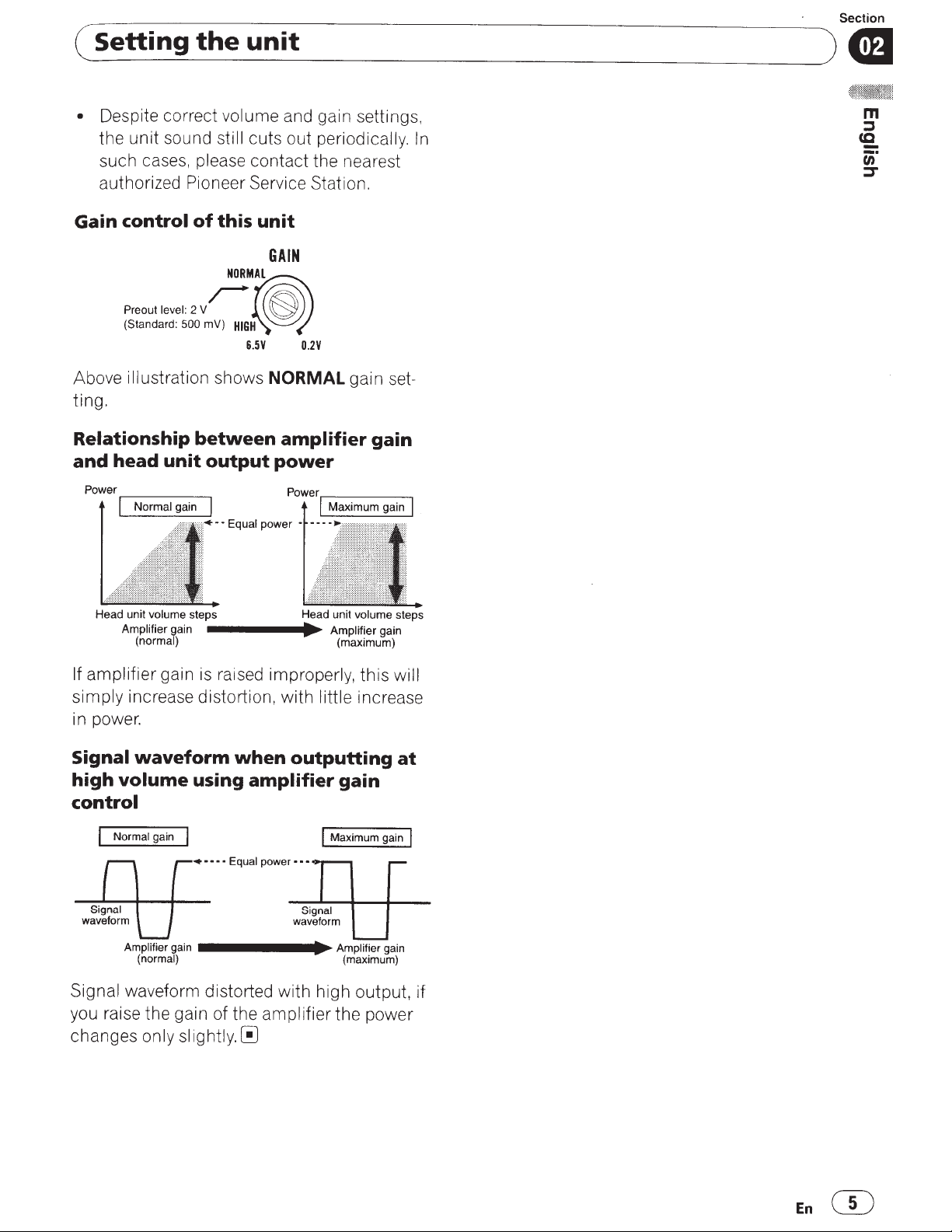
•
Despite correct
the unit sound
such cas
es,
volume
still
please contact the nearest
____________________________
and ga
cuts out periodically.
in
settings,
In
~
)
cml
authorized Pioneer Service Station.
Gain
control
of
this
unit
GAIN
NORMAL
Preout level:
(Standard:
Above
iII
ustration shows
ting.
Relationship
and
head
2
Vr-
500
mV)
between
unit
·~
HIG~~
6.5V
output
• • Equal
0.2V
NORMAL
amplifier
power
Power.-------.
power
• • • • · .
gain s
gain
I
Maximum gain
et-
I
Head unit
volume
Amplifier
(normal)
steps Head unit
gain
____
...
._
Amplifier
volume
(maximum)
If amplifier gain is raised improperly, this
simply increase distortion, with
little
increase
in power.
Signal
high
waveform
volume
when
using
outputting
amplifier
gain
control
• • • • •
Equal
power···
Amplifier
Signal
you raise the gain of the
changes
gain
(normal)
------~Amplifier
(maximum)
waveform distorted with high output, if
amplifier the power
only
slightly.[!]
gain
gain
steps
will
at
En(})
Page 6

Section
m (
Connecting
Connection
the
units
diagram
the following
Please
connection instructions. Refer
when using the speaker
Speaker output
@
Please
connection instructions. Refer to
when
System remote
@
Connect male terminal
tem remote
The
auto-antenna
stereo
connect the
inal
Fuse
@
Fuse
@
@Grommet
Rear side
@
Front side
®
see
terminals
the following section for speaker
see
the speaker
using
control
control terminal
female terminal
relay control terminal.
a system remote
lacks
male terminal
via the ignition switch.
2
x
A)
(25
2
x
A)
(30
section for speaker
input
input
wire
of this wire to the
can
Connections
to
on page
wire
Connections
on page
wire
(sold separately)
of the car stereo.
connected to the
be
the car
If
control terminal,
to the power term-
)
9.
9.
sys-
Special
CD
RD-223
completing all
After
finally
tions,
amplifier
of the
terminal.
Ground wire
®
RD-223
Connect
stereo with
Car
G)
rately)
External output
®
only one input
If
anything to
Connecting
®
parately)
input jack A
RCA
®
input jack B
RCA
(J)
Speaker input
®
cluded)
battery wire
red
(sold separately)
other amplifier connec-
connect the battery wire
to the
(Black)
(sold separately)
metal body or chassis.
to
RCA
RCA input jack
wire with
terminal
positive((£})
output jacks
is
plug
RCA
(use a connector in-
used, do not connect
B.
plugs (sold
pin
terminal
battery
(sold sepa-
se-
Note
select) switch must
INPUT
For
SELECT
details ,
Before connecting
(input
Setting the
see
unit
on page
the
4.
amplifier
AwARNING
Secure the wiring with
•
protect the wiring, wrap sections
cut
To
metal parts in adhesive tape.
insulation
the
sive tape.
contact with
in
Never
•
to feed power to other equipment.
pacity of the wire
cable clamps
of the power
limited.
is
A cAUTION
• Never shorten any wires, the protection
malfunction .
may
• Never ground speaker wire
gether
wires.
multiple
speakers' negative
directly or band to-
or
Current
(8)
set.
be
0
adhe-
supply
ca-
circuit
lead
mEn
Page 7

Section
(~-C_o_n
•
• Install and route the separately sold battery
About
__
n_e_ct_i_n~g_t_h_e
If
the system remote control wire of the ampli-
fier is connected to the power terminal via the
ignition switch
main on with the ignition whether the car
stereo is
if the engine
wire
as
far
Install and route the separately sold battery
wire, ground wire, speaker wires and the am-
plifier
as
na, antenna cable and
bridged
Diagram
A -
(12 V DC),
on
or off, which may exhaust battery
is
at rest or idling.
as
possible from the speaker wires.
far away
Proper
as
__
u_n_it_s
the amplifier
possible from the anten-
tuner.[!]
____________________________
wi
mode
Diagram
B -
Improper
~)
About
II
re-
specification
Ensure speakers conform to the following
standards, otherwise there
smoke
to 8
n,
bridge connections.
suitable
of
speaker
is
a risk of fire,
or
damage. Speaker impedance
or
4 n to 8 n
for
two-channel and other
is
2 n
cmJ
m
·-
::s
(Q
ur
::1"
Subwoofer
Four-channel output
Two-channel output
Three-channel
Speaker output A
Nominal input:
Min.
60W
Nominal input:
Min.
180
W
Nominal input:
60W
Min.
Pioneer
Amplifier
Q
Bridged
4
Speaker impedance
check. Improper connection to the amplifier may
result in malfunction or personal injury due to
burns from overheating.
For
bridged mode for a two-channel amplifier,
with a 4
parallel,
single 4 n speaker.
follow the speaker
bridging shown on
allel for a 4 n load
channel.
For
any further enquiries, contact your local
authorized Pioneer dealer or customer
Mode
is
2 Q
max. 4
Bridged
Mode
n,
please carefully
n load, either wire two 8 n speakers in
Left®
and Right 8 (Diagram A) or use a
For
other amplifiers, please
output
or
connection diagram for
rear:
two 8 n speakers
a single 4 n speaker per
service.[!]
in
par-
Three-channel
Speaker output B
Other
Four-channel output
Two-channel output
Three-channel
Speaker output A
Three-channel
Speaker output B
than
subwoofer
Connecting
The speaker output mode can
three-channel (stereo and mono)
nel (stereo or mono). Connect the speaker
leads based on the mode and the figures
shown below.
Nominal input:
Min. 180W
Max. input:
Min. 120W
Max. input:
Min. 360W
Max. input:
Min.120W
Max. input:
Min. 360W
the
speakers
be
four-channel,
or
two-chan-
En
CiJ
Page 8

Section
m
0
(
Connecting
Four-channel
:
..
~
..
~~
CD
Right
® Left
®
Speaker out A
Speaker out B
the
output
units
Two-channel
output
G)~
rr(]
cnj
+ -
+-~t
___
,
1~1;1~1~
G)
CD
Speaker (Right)
® Speaker (Left)
Two-channel
=
:~
·\:=1~
~
'""'
]·~--
.
output
(Stereo)
~·
~
- +
(Mono)
)
Three-channel
CD
Right
®
Left
®
Speaker out A
0
Speaker out B (Mono)
output
CD
Speaker
(Mono)~
Connections
the
Connect
the
RCA
RCA
the
car
input
input
stereo
jack
when
jack
RCA
of
the
using
output
amplifier.
jack
and
ffi
En
Page 9

(
_c_o_n_n_e_c_ti_n_g_t_h_e_u_n_i_ts
____________________________
Section
)
GDI
Four-channel/
•
Slide
INPUT
to
4CH
position.
CD
RCA
input jack A
@
RCA
input jack B
G)
Connecting
rately)
G)
From
car ste
If only one input plug
car stereo
connect the plug to
than
B.
Two-channel
•
Slide
INPUT
to
2CH
wires with
re
has
position.
Three-channel
SELECT
o
only
output
SELECT
(input
(RCA
output)
is
one output
RCA
(Stereo)
(input
RCA
used,
input jack A rather
output
select)
plugs (sold sepa-
e.g.
select)
when the
(RCA
I
(Mono)
switch
output),
switch
(g)
Connecting
parately)
@
From
car stereo (RCA
wire with
Connections
the
Connect
to
input
•
CD
@
®
@
®
®
(J)
®
®
@
@
speaker
the
car
stereo speaker
the
amplifier
wire.
Do
not
speaker
Car
Stereo
Speaker output
White/black:
White:
Gray
Gray:
Green/black:
Green:
Violet/b
Violet:
Speaker input connector
To
CH
/b
lack:
CH
CH
CH
speaker input terminal of this
using
connect
input
CH
A,
Left
CH
A,
Right
CH
B,
Left
la
ck:
CH
B.
Right
both
at
the
A,
c±>
A,
Right
c±>
B,
c±>
B, Right
RCA
pin plugs (sold
output)~
when
input
the
supplied speaker
the
same time.
Left
8
using
wire
output
RCA
input
8
Left
8
8
c±>
unit.[!)
wires
and
se-
the
CD
RCA
For
two-channel output, connect the
plugs to the
input jack A
RCA
t
•
Q
vn
input jack
A.
RCA
Connecting
terminal
The use
wire RD-223,
mended.
the
ground
of
a special red battery and
available
Connect
car
battery positive
wire to the
the
the
car
power
separately, is recom-
battery wire
terminal
body.
ffi
ground
directly
and
the
to
En
CD
Page 10

Section
ID \ Connecting
A
wARNING
If
the battery wire
inal using the terminal screws, there
overheating, malfunction and injury, including
minor burns.
1 Route battery wire from engine
partment
After
tions,
of
the
terminal.
to
completing
finally
am
pi
is
not securely fixed to the term-
the vehicle interior.
all
other
connect
ifier
to
the
the
the
positive ((f)) battery
units
is
amplifier
battery wire
connec-
a risk of
com-
terminal
CD
Lug
(sold separately)
W Battery wire
® Ground wire
4 Connect the wires to the terminal.
Fix
the
wires securely with
screws.
the
terminal
CD
Positive ((f)) terminal
(g)
Engine compartment
® Vehicle interior
@
Fuse
(30
A)
x 2
® Insert the 0-ring rubber grommet into the
vehicle
® Drill a
2 Twist the battery wire, ground wire
and system remote control wire.
body.
14
mm hole into the vehicle
body.
Twist
---·
3 Attach
Use pliers, etc.,
lugs
to wire
to
crimp
ends.
lugs
to
wires.
CD
System remote control terminal
(g)
Ground terminal
® Power terminal
@ Terminal screws
® Battery wire
® Ground wire
(j) System remote control
Connecting
output
1
Use
strip the end
pose
about 10 mm (3/8 in.)
then twist the wire.
terminals
wire cutters or a utility knife
the
of
the speaker wires
wire[!]
speaker
to
of
wire and
Twist
to
ex-
@En
-tz=i
r--r
10
mm
(3/8
inch)
Page 11

Section
(~c_o_n_n_e_c_ti_n_g_t_h_e_u_n_i_ts
2 Attach
Use
pliers, etc.,
CD
Lug
lugs
to
wire ends.
to
crimp
(sold separately)
lugs
to
__________________________
wires.
~)~
m
::::s
cc
c;;-
::::r
W Speaker wire
3 Connect the speaker wires to the
speaker output terminals.
Fix
the
speaker wires securely
inal screws.
with
the
term-
CD
Terminal screws
W Speaker wires
® Speaker output
terminals~
En
@
Page 12

Section
1m)
(
.
~1
-
n_s_t_a_ll_a_ti_o_n
Before
A
wARNING
•
To
parts in the manner specified.
other than those supplied are used, they may
damage internal parts of the amplifier, or
come loose causing the amplifier to shut
down.
• Do not install
-
-
• Install tapping screws in such a way that the
screw tip does not
portant to prevent wires from being cut
bration of the
• Make sure that wires do not get caught
sliding mechanism of the seats or touch the
legs of a person
may result.
•
When drilling to install the amplifier, always
confirm no parts are behind the panel and
protect all cables and important equipment
g.
installing the amplifier
ensure proper installation, use the supplied
Places
passengers if the vehicle stops suddenly.
Places
ver,
ver's seat.
fuel/brake lines, wiring) from damage.
where it could injure the driver or
where it may interfere with the dri-
such
as
------------------------------
If
an
y parts
be-
in:
on
the floor
touch
car,
which can result in fire.
in
the vehicle
in
front of the
any wire. This
as
short-circuit
is
by
in
dri-
im-
v
the
i-
(e.
--
•
The optimal installation location differs
pending
fier at a sufficiently rigid
•
Firstly make temporary connections and
check to ensure the amplifier and system
erate properly.
•
After installing the amplifier, confirm that the
spare tire, jack and tools can
moved.[!]
Example
the
1
Place
on
the car model. Secure the ampli-
of
floor
mat
the amplifier
location.
be
easily
installation
or
chassis
in
the desired instal-
de-
op-
re-
on
lation location.
Insert
18
screws
print
cated.
2
the
mm)
into
with
where
Dri112.5
supplied
the
a
the
tapping
screw
screwdriver
installation
holes and
screws
so
they
holes are
(4
push
make
mm (1/8 in.) diameter holes
mm
on
to
an
be
x
the
im-
lo-
at
the imprints either on the carpet or directly
on the
3
supplied tapping
chassis.
Install
the amplifier
screws
with
(4
mm
the
use
x
18 mm).
of
A
cAUTION
•
To
ensure proper heat dissipation of the
fier, ensure the following during installation:
- Allow adequate space above the amplifier
for proper ventilation.
-
Do
not cover the amplifier with a floor mat
or carpet.
• Protection function may activate to protect the
amplifier against overheating due to installation
in
locations where sufficient heat cannot
be
dissipated, continuous use under
lume conditions, etc.
plifier shuts down until it has cooled to a
certain designated temperature.
• Avoid routing wires through hot areas, such
as
near the heater outlet. Heat may damage
the insulation, resulting in a short-circuit
through the vehicle
(ill
En
In
such cases, the
body.
ampli-
high-vo-
am-
Q)
Tapping-screws
@
Drill a
2.5
®
Floor mat or
(4
mm
(1
chassis[!]
mm
x
18
mm)
/8
in.) diameter hole
Page 13

(_
__ d-
A_d
it_i_o_n
_a_l-
f_o_r_rn
_
in
__
a_t_io-n----------------------------~
Appendix
)
Specifications
source
Power
Ground1ng system
Current
Average current drawn
...............................................
se
Fu
Dimensions (W
Weight
imum
x
Ma
Continuous
Load impedance ..
equency response
Fr
Signal-to-noise
stortion
Di
Low pass
(Ach)
Cut
Cut
Bch)
(
Cut
Cut
High pass
h)
(Ac
Cut
Cut
(Bch)
Cut
Cut
control:
Gain
RC
Speaker
mum
xi
Ma
RCA
Speaker
.............................
...................
consumption
..........................................
power output
power output
...................................
filter:
off frequency
slope
off
off frequency
slope
off
filter:
off frequency
slope
off
off frequency
slope
off
.........
...
A
........................
input
......................................
...........
............
.
....
0 )
H x
x
......
............
.
.......
....
..
...
..
..............
ratio
...........
.....................
...........
......
.
..
..
......
.........
.....................
...........
................
........................
eve
l
.
......
imp
I
l
..................
.
....
.
...
.
...
...
.
.
..
.
..
.
..
....
..
edance:
V to 1
0.8
(1
DC
V
14.4
allowable)
Negative type
A (at continuous power,
32
4Q)
for four channel
n
(4
9 A
for two
n
(4
15 A
A x 2
25
x
mm
289
mm
(11·3/8
2
3.3
cluded)
760W
60
20Hz to
85
4
3d
98
0
-12
-12
-12
-
in. x2-1/2 in.
in)
(7.3
kg
(Leads for wiring not
0W x
(19
(a
W x 4
20
+N)
2
x
180W
BRIDGE
+
1kHz
0Hz
1
80
40
80
40
12
200
0.8 V
6 5 V
26
1
N)
W x 4 (at 14.4
1%
~
,
to
n
(2
n
70k
to
B)
dB (IHF-A
0
(1
05%
Hz
dB/oct
500
to
Hz
/oct
dB
Hz
dB/oct
500
Hz to
/oct
dB
mV to
26
to
kn
22
I
kQ
22
VI
channels)
x
mm
62
lbs)
4)
V.
14.4
t
1 % THO
kHz~
V.
14.4
(at
1%
kHz,~
V,
THD+N)
owabl
ll
n a
8
+0
Hz (
network)
Hz)
1 k
W,
Hz
Hz
V
6.5
V
5.1
349
x
in-
Q
4
40
THO
2n.
dB
1ft.
e)
. -
V
s)
CEA2006 Specifications
output
Power
S/N ratio
...........
...
...
.
...
............
.
................
............
.
..
60 W RMS x 4
..
.
4Q
V,
14.4
)
+N
dBA (reference: 1 W into
80
)
4Q
Channels
and~
Notes
Specifications and the design are subject to
•
modifications without notice.
The average current drawn is
•
current drawn by this unit when an
mum
input. Use this
signa l
audio
working out
power
is
total
amplifier
current drawn
s.[!]
nearly the
value
multiple
by
1% THO
max
when
t
(a
i-
En@
Page 14

Register your product
at
Enregistrez votre produit au
Registre su producto en
http://www.pioneerelectronics.com
See "Visit our website
Voir
Ia
page "Visitez notre site Web"
Consulte
Ia
pagina sobre "Visite nuestro sitio Web"
PIONEER CORPORATION
1-1,
Shin-ogura,
Kanagawa
PIONEER ELECTRONICS (USA) INC.
P.O.
Box 1540, Long Beach, California 90801-1540, U.S.A.
TEL: (800) 421-1404
PIONEER EUROPE NV
Haven 1087, Keetberglaan
TEL: (0) 3/570.05.11
PIONEER ELECTRONICS ASIACENTRE PTE. LTD.
253 Alexandra Road, #04-01, Singapore 159936
TEL: 65-6472-7555
PIONEER ELECTRONICS
5 Area Lane, Heatherton, Victoria, 3202 Australia
TEL: (03) 9586-6300
PIONEER ELECTRONICS OF
340 Ferrier Street, Unit
TEL: 1-877-283-5901
TEL: 905-479-4411
PIONEER ELECTRONICS DE MEXICO, S.A.
Blvd.Manuel Avila Camacho 138 10 piso
Coi.Lomas de Chapultepec, Mexico,
TEL: 55-9178-4270
$£Hft~ffifif~.IH1
t5~trnl*l~AA~IfM:7t~~4o75m8tt
~~3
:
(02)
$1til~::F
(
•~ft~~~@~~•mw••~~
9tl901-6~
'li~3
:
(0852)
Saiwai-ku, Kawasaki-shi,
212-0031,
JAPAN
1,
B-9120 Melsele, Belgium/Belgique
AUSTRALIA
2,
Markham, Ontario L3R 2Z5, Canada
6.1
2657-3588
fi~§ ) fif~N~
2848-6488
6.1
CANADA,
D.F.
PTY. LTD.
INC.
de
C.V.
11000
"page
© 2011 PIONEER CORPORATION. All
rights reserved.
© 2011 PIONEER CORPORATION. Taus
droits
de
reproduction et de traduction
reserves.
<KNAZX>
<11
COOOOO>
in
Printed
lmprime en Chine
China
<5707000005510>UC
Page 15

PIONEER ELECTRONICS
(USA)
INC.
GARANTIE
VALIDE
SEULEMENT
GARANTIE LIMITEE . . .
DANS
LE
PAYS
OU
LE
GARANTIE
Pioneer Electronics (USA)
avoir
ete installes
vice de fabrication, seront
Les unites ou pieces
LA
PRESENTE
A
CONDITION
OU
UNE
LA
PREMIERE
PAYS
PUSA
PERIODE
Produits
La
periode
ELEMENTS
UN
PRODUIT
IMPLICITE
"AVEC
PIONEER N'EST PAS RESPONSABLE
PIONEER
DE TOUTE APPLICATION INDUSTRIELLE OU COMMERCIALE QUE
LA
PRESENTE GARANTIE
DOCUMENTS S'Y APPLIQUANT.
LA
PRESENTE GARANTIE
PENDANT
LA
PRESENTE GARANTIE
DISQUES
PAR
LES DOMMAGES SUBSEQUENTS DECOULANT
CONFORMES
LA
PRESENTE GARANTIE
PRESENTE GARANTIE, Sl ELLES SONT OBTENUES AUPRES D'UNE SOURCE AUTRE QU'UNE SOCIETE
PIONEER.
NON AUTORISEES, Nl D'UN ENTRETIEN INADEQUAT.
LES NUMEROS
INVALIDITE
AUX
DE
QUALITE MARCHANDE
APRES
L'EXCLUSION OU
S'APPLIQUER
ETAT
AU
CANADA-
QU'ELLE SOIT IMPLICITE, OBLIGATOIRE
GARANTIE
QUE
AUTRE
PREUVE
LOCATION.
OU
L'ACHAT A
OU
POC,
LE
DE
stereo
de
garantie pour les clients
NON
ACHETE
DE
QUALITI~
TOUS SES DEFAUTS EVENTUELS
NE
GARANTIT PAS LES PRODUITS ENUMERES CI-DESSUS LORSQU'ILS SONT UTILISES A DES FINS COMMERCIALES
DE
LONGUES PERIODES (IMAGES REMANENTES).
OU
AUX RUBANS
ECRIT
PAR
A
LA
PRESENTE GARANTIE
DE
LA
PERIODE
A
L'AUTRE.
DE
A
SOUS RESERVE
ETATS-UNIS-
Inc.
et utilises
LE
PRODUIT
ETE
CAS
(PUSA) et Pioneer Electronique du Canada,
conformement au manuel
repares
de
ECHEANT,
ou
rechange fournies en vertu
LIMITEE
S'APPLIQUE
AIT
ETE
D'ACHAT
VALIDE
Sl
JAMAIS
EFFECTUE
UN
SEULEMENT,
PAIERA
remplaces
ACHETE
INDIQUANT
SERVICE
POUR
de
par une
de
AU
PROPRIETAIRE
CHEZ
UN
LA
DE
REPARATION
TEL
QU'IL
VOUS
RETOURNER
l'utilisateur
unite
de valeur comparable, au choix
Ia
presente garantie peuvent
INITIAL
DISTRIBUTEUR
DATE
DE
L'ACHAT
EST
EST
EXPLIQUE
inclus avec
AINSI
OU
MARCHAND
REQUIS,
DANS
LE
PRODUIT
Inc. (POC)
INITIAL
GARANTIE DES PRODUITS
pour l'auto ......... ...
qui
louent
COUVERTS
CHEZ
UN
MARCHANDE
NE
S'APPLIQUE PAS Sl
NE
COUVRE PAS LES TELEVISEURS
NE
COUVRE PAS
OU
PIONEER, D'UN ACCIDENT, D'UN USAGE INAPPROPRIE
CELLES QUI SONT SPECIFIEES DANS
SERlE MODIFIES, OBLITERES
TOUTE
PIONEER LIMITE SES OBLIGATIONS
DE
LA
LIMITATION DES DOMMAGES CONSECUTIFS
VOUS.
DISQUES D'ENREGISTREMENT, LES DOMMAGES AU PRODUIT DECOULANT D'UNE RETOUCHE, D'UNE MODIFICATION NON AUTORISEE
NE
COUVRE PAS
AUTRE
OU
D'ADAPTATION
GARANTIE. CERTAINS ETATS
LA
PRESENTE GARANTIE VOUS DONNE DES DROITS LEGAUX SPECIFIQUES. VOUS POUVEZ JOUIR D'AUTRES DROITS, QUI PEUVENT VARIER D'UN
DE
... ....
..
.... ... ....
..
.....
..
.... ... .... ...... .
le
produit commence
PAR
DISTRIBUTEUR NON AUTORISE N'EST COUVERT
LA
OU
D'ADAPTATION
".
DE
QUELQUE DOMMAGE CONSECUTIF ET(OU) INDIRECT QUE
LE COFFRAGE
LE
NE
COUVRE PAS LES DEFECTUOSITES
le
jour
ou
le
produit est utilise pour
GARANTIE
A
UN
USAGE PARTICULIER QUE
LE
PRODUIT
DE
FUITES, LES DOMMAGES DECOULANT
LE
COOT DES PIECES
OU
ENLEVES ANNULENT LA
CE
A
ETE SOUMIS
OU
LES ECRANS ENDOMMAGES
OU
LES ELEMENTS ESTHETIQUES, LES ANTENNES INSTALLEES
MANUEL DE
OU
GARANTIE
EN
VERTU
DE
A
UN
USAGE PARTICULIER,
NE
PERMETTENT
CE QUI EST EXPRESSEMENT STIPULE DANS LES PRESENTES, AUCUNE REPRESENTATION, GARANTIE, OBLIGATION
OU
AUTRE,
NE
S'APPLIQUE
TOUTE GARANTIE IMPLICITE QUE CE
OU
garantissent que
l'unite,
ne fonctionnent pas de
de
QU'A
SOIT.
DE LA
ACE
etre neuves
TOUT
PROPRIETAIRE
PIONEER
OU,
Sl
LE
L'UTILISATEUR.
A
PAS
INDIRECTS. LES LIMITATIONS
VOUS
PRODUIT
LE
REP
OU
DOlT
PRESENT
..
UNE PERIODE
LA
PRODUIT.
DOCUMENT.
ARE
OU
REMPLACE,
. ... ....... ... ... . ... ... ... .... ... ... ... .... ...... ....... ............. ... ... ..... 1
Ia
premiere
PAR
A
UNE PUISSANCE NOMINALE
D'UN USAGE ABUSIF, LES DOMMAGES PRODUITS
MAIN-D'CEUVRE QUI SERAIENT AUTREMENT OFFERTES SANS FRAIS
OU
LES DOMMAGES CAUSES
PRESENTE GARANTIE DANS SA TOTALITE.
LIMITATION
les
produits distribues par PUSA aux Etats-Unis et par POC au Canada qui,
PUSA ou
de
POC,
ou remises
SUBSEQUENT
AUTORISE
LOUEZ
~TRE
fois
AUCUNE GARANTIE EXPRESSE
AUX
LE
PRODUIT,
EXPEDIE
VOUS
A
L'INTERIEUR
(a)
pendant
CE
SOIT.
EN
DE
PILES DEFECTUEUSES
N'EXCEDANT
DE
LA
DUREE D'UNE GARANTIE IMPLICITE,
SERVICE
Pour
profiter
du
service
en vertu
de
Ia
indiquant
AUX
Votre
de
Votre
Veuillez
de
Pioneer Electronics
ci
AU
Communiquez
Expedition
en
pendant
Pour
Satisfaction
Pour
REGLEMENT
AUX
recours
de
Improvement
Pour
probleme
distributeur
resolution
par
a
AU
NO.
Date d'achat : Achete
ETATS-UNIS-
marchand
caisse
societe
acceder
service
-dessous
CANADA
port
prepaye
le
toutes
le
raccordement
ETATS-UNIS
au
resolution
avoir
ecrit
pour
votre
plainte
CANADA
du
modele :
l'endroit
et
Pioneer
devrait
enumerer
de
service
au site
Pioneer
Ia
Service-
pour
communiquer
-
POC
avec
de
votre
et
selon
transport
.
les plaintes
de
Ia
clientele
DES CONFLITS
- Si
Programme
des
plaintes
Act,
15
recours
auquel
vous
I
marchand
vous
sera
vous
par
ecrit
-
Communiquez
_________
Ia
date
de
Communiquez
autorise-
ses
autorisee-
Web
de
plus proche.
Ce
a
designe
Pioneer
unite
aux
une
lncluez
et
problemes
au 1-877-283-5901.
ou le
fonctionnement
PIONEER
un
conflit
de
resolution
avant
U.S.C. 2301
au
Programme
faites
autorise
communique.
aviser
des
pour
garantie aux Etats-Unis
Ia
transaction
avec
Votre
coordonnees
Celle-ci
Pioneer
service peut vous aviser
avec
un certain
Electronique
fins
methode
votre nom,
LONG
http://www
se
de
vous
et
face
et
aupres
demarches
vous
avec
par
un
des
marchand
(numeros
peut
a
www.pioneerelectronics.com, cliquer
Pioneer
par
nombre
du
Canada
de
service
de
transport
votre
adresse
aux Etats-Unis ,
de
votre
AUX
ETATS-UNIS
ELECTRONICS
P.
O.
BOX
BEACH,
CALIFORNIA
1-800-421-1404
.
pioneerelectronics.com
produit
entre
des
plaintes
prevaloir
s.s.
de
resolution
les
demarches
duquel
Pioneer
etudiera
qu'elle
indiquer
le
directeur
_
__________
les
ENREGISTREZ
le
premier
partenaires
Pioneer
reparer
telephone,
de
societes
- Si
vous
pouvant
unite, ou
1760
vous
de
de
des
vous vous
entreprendra
raisons
de
Ia
PRENEZSOINDEGARDERCETIEINFORMATlONETVOTREREQUD'AQ-IATDANSUNENDROITsUR
et
au Canada,
proprietaire.
Pioneer
peut
reparer ou
de
telephone
Ia
plupart
des
options
par
courrier
de
(les
et
communiquez
SERVICE
Pioneer
vos
que
le
Satisfaction
serv
coordonnees
expediez
etre
un
numero
pour
, INC.
90801
et
Pioneer
pour
droits
plaintes,
vous
avez
etes
conflit
pour
LE
suivie
et,
suivants
remplacer
et
de
telecopieur,
des
produits
de
service optimales
ou
par
ice autorisees
se
trouvent
l'unite,
vous
et
assuree
de
telephone
avec
le service
trouver
une
apres
Ia
resoudre
ou de
chercher
appelez
au 1 800
entreprises
procure
dans
un
pour
resoudre
lesquelles
de
Ia
clientele
LIEU ET
LA
_
__
vous
devez
presenter
pour
le
service:
votre
courriel ,
electroniques
sur
l'onglet
pour
le biais
de
partout
ci-dessous)
devez
l'emballer
.
Emballez
ou
nous
de
Soutien
societe
de
reponse
le
delai
elle
DATE D'ACHAT
a
le
conflit.
Ce
reparation
421-1404
pour
produit
faire
Pioneer.
de
quarante
le
conflit,
n'entreprendra
au (905) 946-7446
NO.
deserie
de:------------------------------
votre
unite, ou bien
etc
.).
pour
l'auto
II
Service and
votre
modele
son site
Web.
au
Canada
si
pour
trouver
soigneusement
le
produit
pouvons
vous
a
Ia
clientele au
service
autorisee
une
demande
programme
en
vertu
du
et
expliquez
reparer
le
Une
fois
(40)
jours
et
indiquera
aucune
POUR REFERENCE ULTERIEURE
:
____________________________
PIONEER ELECTRONIQUES
PRODUIT
fac;:on
a
ETATS-UNIS
PENDANT
~TES
A
ETE
ACHETE
appropriee dans des conditions d'utilisation normales en raison d'un
sans que vous deviez payer pour
neuf, au choix
DU
VOTRE
RESPONSABLE
PRESENT
OU
CONTRAT
LA
PERIODE
DU
PAYS
de
PRODUIT
AU
CANADA.
OU
PUSA
DE
LOCATION
DE
GARANTIE,
DU
DEMONT
L'ACHAT A
ou
de
PIONEER
VOUS
ETE
les pieces ou
POC.
PENDANT
DEVREZ
INDIQUANT
EN
AGE
ET
EFFECTUE.
Pieces
les
LA
FOURNIR
L'ENDROIT
PORT
PREP
DE
L'INSTALLATION
DU
CANADA, INC.
travaux de reparation.
PERIODE
UN
RELEVE
AYE,
Main-d'muvre
an
Ia
periode
de
location
ou
(b)
apres
Ia
vente
au
detail,
selon
ce
qui
se
produ
OU
DE
PLUS,
CE
PRODUIT EST STRICTEMENT VENDU
CE
SOIT.
EXCEDANT CELLE QUI
RAISON
DE
L'APPLICATION D'IMAGES STATIQUES
DE
SERVICE OU AUTRE AUTORISEE
PAR
L'UTILISATION D'UNE MAIN-D'CEUVRE
SOIT,
Y
PAS
ET EXCLUSIONS
releve
vous
et
vous
Support
et
votre
jamais
une
au
moyen
joindre
,
GROUPE
PIONEER
initiale
vous
Titre
au
produit
que
a
pres
combien
demarche.
pour
discuter
COMPRIS
LA
PERIODE
de
caisse
diriger
vers
aviser
II
et
choisir
emplacement
vous
avez
societe
et
l'envoyer
de
materiaux
pendant
1-800-421-1404
appelez
ou
DE
SATISFACTION
ELECTRONIQUES
340
FERRIER
MARKHAM,
http://www
faite
au
est
offert
I
de
Ia
lol
representant
pendant
votre
plainte
Ia
reception
de
de
IMPLICITE, Y COMPRIS QUELQUE GARANTIE
OU
PROFESSIONNELLES,
A ETE ETABLIE DANS LES
PAR
L'UTILISATEUR, LES DOMMAGES AUX
PAR LA
OU
DE
L'UTILISATION
ENTRE
DE
GARANTIE. AUCUNE GARANTIE
ETABLIES
ou, si
vous
une
societe
des
options
supplementaires
II
Authorized Service Locator
geographique.
besoin
de
de
service autorisee.
a
une
societe
coussines
les
heures
.
Au Canada,
ecrivez
a
:
AU
CANADA
STREET
ON
(905)
4 79-4411
1-877-283-5901
.pioneerelectronics.ca
service
de
frais.
du
service
periode
a
ete
de
ces
plainte
Soutien
Vous
expliquee
votre
sans
Magnuson-Moss
Ia
temps
votre
FOUDRE
AUTRES LES GARANTIES IMPLICITES
ET CERTAINS
CI-DESSUS PEUVENT DONC
louez
le
de
service
Veuillez consulter
services
de
adequats
de
bureau.
communiquez
DE
LA
DU
CANADA
,
UNIT
L3R
2Z5
a
devez
Warranty-Federal
a
Ia
de
garantie,
au
plainte,
demarches
et
resoudre
OU
DE
OU
produit,
Pioneer
de
reparation
service
CLIENTELE
2,
Ia
clientele,
avoir
clientele
representant,
(1)
prendront
LA
PILES NON
EN
VERTU
DESIGNEE
OU
NE
PERMETTENT
votre
contrat
autorisee. Votre
qui pourraient s'appliquer.
II
pour trouver
pour
autorisee
pour
eviter
,
INC.
vous
recours
Trade
qui
puis
donnez-lui
repondra
rapidement
"TEL
ET
avec
vous
;
<
apres
DE
GARANTIE,
DE
CAISSE
ET
LA
DATE
PRODUIT.
1
an
premier.
ET
AU SEIN
DE
LA
PIECES
PAS
NE
PAS
de
location
rec;:u
Ia
societe
a
Pioneer,
dommages
groupe
avoir
le
nom
numero
plainte
repondra
probleme.
_
DE
DU
de
du
de
le
A
L'INTERIEUR
DU
it
en
QUEL"
OU
IMMOBILES
SURTENSION,
PAR
DE
NE
S'APPLIQUE
OU
CONDITION,
les
coordonnees
votre produit.
ou
les
le
pouvez
au
Programme
Commission
repondra
un
a
votre
ou
(2)
le
5727000000271
lmprime
en
Ch
i
>
ne
Page 16

PIONEER ELECTRONICS (USA) INC.
PIONEER ELECTRONICS OF CANADA, INC.
LIMITED WARRANTY
WARRANTY VALID ONLY
WARRANTY
Pioneer Electronics (USA) Inc. (PUSA), and Pioneer Electronics Of Canada, Inc. (POC), warrant that products distributed
function properly under normal use due to a manufacturing defect when installed and operated according to the owner's manual enclosed with the unit will
unit of comparable value, at the option of PUSA or POC, without charge to you for parts or actual repair work. Replacement units and/or parts supplied under this warranty may be
new or rebuilt at the option of PUSA or POC.
THIS LIMITED
PRODUCT
RECEIPT
AND
ONLY
PRODUCT.
WARRANTY
WAS
PURCHASED FROM
OR
OTHER
DATE OF FIRST RENTAL. IN THE EVENT SERVICE IS REQUIRED, THE PRODUCT MUST
FROM WITHIN THE COUNTRY OF
PUSA
OR
APPLIES
VALID
POC,
TO THE
ORIGINAL
AN
PROOF OF PURCHASE SHOWING THE DATE OF
AS
APPROPRIATE,
AUTHORIZED PIONEER DISTRIBUTOR/DEALER IN THE U.S.A.
PURCHASE
WILL
ORA
NY SUBSEQUENT OWNER OF THIS PIONEER PRODUCT DURING THE
AS
EXPLAINED
PAY
TO RETURN THE REPAIRED OR
PRODUCT WARRANTY PERIOD
Car
Stereo
The warranty period for retail customers who rent the product commences upon the date product is first put into use
WHAT
IF THIS PRODUCT WAS PURCHASED FROM AN UNAUTHORIZED DISTRIBUTOR, THERE ARE NO WARRANTIES, EXPRESS OR IMPLIED, INCLUDING THE IMPLIED WARRANTY
OF MERCHANTABILITY AND THE IMPLIED WARRANTY OF FITNESS FOR A PARTICULAR PURPOSE AND THIS PRODUCT IS SOLD STRICTLY
PIONEER SHALL NOT BE LIABLE FOR ANY CONSEQUENTIAL AND/OR INCIDENTAL DAMAGES.
PIONEER DOES NOT WARRANT ANY PRODUCT LISTED ABOVE WHEN IT
THIS WARRANTY DOES NOT APPLY IF THE PRODUCT HAS BEEN SUBJECTED TO POWER IN EXCESS OF ITS PUBLISHED POWER RATING.
THIS WARRANTY DOES NOT COVER DISPLAY SCREENS DAMAGED
THIS WARRANTY DOES NOTCOVERTHECABINETORANY APPEARANCE ITEM, USER A TTACHEDANTENNA,ANY DAMAGE TO RECORDS OR RECORDING TAPES ORDISCS,ANY
DAMAGE TO THE PRODUCT RESULTING FROM ALTERATIONS, MODIFICATIONS NOT AUTHORIZED
LIGHTNINGORTOPOWERSURGES,SUBSEQUENTDAMAGEFROM LEAKING, DAMAGE FROM INOPERA TIVEBA TTERIES,ORTHEUSEOFBA TTERIESNOTCONFORMINGTOTHOSE
SPECIFIED
THIS WARRANTY DOES NOT COVER THE COST OF PARTS OR LABOR WHICH WOULD BE OTHERWISE PROVIDED WITHOUT CHARGE UNDER THIS WARRANTY OBTAINED FROM
ANYSOURCEOTHERTHANAPIONEERAUTHORIZEDSERVICECOMPANYOROTHERDESIGNA TEDLOCA TION. THISWARRANTYDOESNOTCOVERDEFECTSORDAMAGECAUSED
BY
THE USE OF UNAUTHORIZED PARTS OR LABOR OR FROM IMPROPER MAINTENANCE.
ALTERED, DEFACED, OR REMOVED SERIAL NUMBERS VOID THIS ENTIRE WARRANTY
Products
IS NOT COVERED
IN
THE OWNER'S MANUAL.
NO OTHER WARRANTIES
IN
THE
U.S.A.-
MERCHANTABILITY
WARRANTY PERIOD. SOME STATES DO NOT
OR
LIMITATIONS OF INCIDENTAL OR CONSEQUENTIAL DAMAGES, SO THE
YOU SPECIFIC
CANADA-
IN
OR
OTHERWISE,
PIONEER
LEGAL
EXCEPT AS EXPRESSLY PROVIDED HEREIN, THERE
APPLICABLE
AND
RIGHTS
LIMITS
FITNESS
ITS
FORA
AND
YOU
TO THIS PRODUCT.
OBLIGATIONS
PARTICULAR PURPOSE, TO A PERIOD NOT TO EXCEED THE WARRANTY PERIOD. NO WARRANTIES
ALLOW
MAY
UNDER
ANY
LIMITATIONS ON HOW LONG AN IMPLIED WARRANTY LASTS
HAVE
OTHER RIGHTS WHICH
TO OBTAIN SERVICE
In
the
U.S.A.
or
Canada to receive warranty service you need to present
~-
Please
contact
one
of
the
following
Your
Authorized Pioneer
the
contact
list
Your
Authorized
Pioneer
Pioneer
or
email
~-
Shipping
Use adequate padding material to prevent damage
information (phone number, fax, email, etc.)
website
Electronics Service - Can advise
access the Pioneer website to contact Pioneer.
POC has a number of Authorized Service Companies should your product require service. Contact Pioneer
Your
Unit
On all complaints and concerns
Dealer-
Your
Pioneer
Service
at
www.pioneerelectronics.com
for
Service-
Company
Please package it carefully and send
in
For hook-up
and
operation of your unit or
Pioneer
Pioneer Dealer may repair or replace your unit, or refer you to an Authorized Pioneer Service Company.
- Can perform repairs
the
optimal service option
partners
and click on
in
transit. Include your name, address and telephone number where you can be reached during business hours.
for
to
your
Service
the U.S.A. call Customer Support at 1-800-421-1404, or,
IN
THE
U.S.A.
to
locate
Authorized Service Company, please call or write: CUSTOMERSATISFACTIONGROUP
PIONEERELECTRONICSSERVICE,
INC.
P.O. BOX 1760 340FERRIERSTREET,UNIT2,
LONG BEACH, CALIFORNIA 90801 MARKHAM,
1-800-421-1404 (905) 4 79-4411 1-877-283-5901
http://www.pioneerelectronics.com http://www.pioneerelectronics.ca
DISPUTE RESOLUTION
IN THE
U.S.A.Resolution Program to resolve
before you exercise
To
use the Complaint Resolution Program
to have the product repaired during the warranty period and
has been explained to
(1) respond to
informing you
CANADA-
IN
Following our response to
any
your
complaint
why
it will not take
Call the
the dispute.
rights under,
the
representative, a resolution
in
writing informing you
any
Customer
Satisfaction
any
initial request to
The
or
action.
Complaint Resolution Program is available to you without charge. You are required to use the Complaint Resolution Program
seek
any
remedies, created by Title I of the Magnuson-Moss Warranty-Federal Trade Commission Improvement
call1-800-421-1404
Manager
Customer
and explain to the
the
name of the authorized Distributor/Dealer from whom the Pioneer product was purchased. After the complaint
number
will be issued. Within 40 days of receiving
what
action Pioneer will take, and
at (905) 946-7446 to discuss
IN
COUNTRY OF PRODUCT PURCHASE
by
PUSA
in
the U.S.A, and
OR
ORIGINAL
IN THIS DOCUMENT. YOU
IS
USED
BY
STATIC, NON-MOVING, IMAGES APPLIED FOR LENGTHY PERIODS (BURN-IN).
IMPLIED
ABOVE
MAY
ARE
NO REPRESENTATIONS, WARRANTIES, OBLIGATIONS
your
sales receipt or your rental contract showing place and date
obtain
service:
Dealer.
for
most
Car
and
Support
for
your
model and
it,
transportation prepaid by a traceable, insured method, to an Authorized Service Company or Pioneer.
an
PURCHASE OR, IF RENTED,
BE
DELIVERED WITHIN THE
WILL
REPLACEMENT
IN
A TRADE OR BUSINESS OR IN ANY INDUSTRIAL OR COMMERCIAL APPLICATION.
IN
WRITING BY PIONEER, ACCIDENT, MISUSE OR ABUSE, DAMAGE DUE TO
WARRANTIES
LIMITATIONS
VARY
Electronics products and can advise other options as applicable. Please access the
INCLUDING,
FROM STATE TO STATE.
and select
geographic
OR
Authorized
For additional information
CANADA.
BE
RESPONSIBLE
PRODUCT TO YOU WITHIN THE COUNTRY OF PURCHASE.
(a)
during the rental period or
BUT
EXCLUSIONS
location. Please reference
in
Canada, call Customer Satisfaction at 1-877-283-5901.
YOU
WILL
YOUR
WARRANTY
NOT
LIMITED
AND
SOME STATES DO NOT
MAY
Service
Locator
of
Canada as listed below to obtain a local service location.
IN
on
BE
RENTAL
PERIOD, TRANSPORTATION PREPAID,
FOR
REMOVAL
TO, THE
NOT
APPLY
OR
to find the nearest
the
CANADA
this warranty, please call or write:
PIONEER ELECTRONICS
ON
Support, should a dispute arise between you and Pioneer, Pioneer makes available its Complaint
customer
service representative the problem you are experiencing, steps you have taken
your
in
what time period, to resolve the dispute;
your
complaint and to obtain a prompt resolution.
complaint, Pioneer will investigate the dispute and will either:
or
by
POC
in
Canada that fail to
be
repaired or replaced with a
WARRANTY
REQUIRED TO PROVIDE A
CONTRACT SHOWING THE
(b)
TO YOU. THIS
CONDITIONS, IMPLIED, STATUTORY
information listed below and phone,
OF
CANADA,
PERIOD PROVIDED THE
AND
INSTALLATION
Parts
1
retail sale, whichever occurs first.
"AS
Year
IS" AND "WITH
IMPLIED
SHALL
ALLOW
of
original owner's transaction.
Your
ALL
WARRANTIES
APPLY AFTER THE
THE EXCLUSIONS
WARRANTY
sales receipt should
Pioneer
INC.
L3R 2Z5
Act,
15
U.S.C.
2301
(2) respond to your complaint
SALES
PLACE
OF THE
Labor
1
Year
FAULTS".
GIVES
servicer.
et
in
writing
OF
seq.
Model No.
PumhasedFrom
__________________
RECORDTHEPLACEANDDATEOFPURCHASEFORFUTUREREFERENCE
---------------------------------------------------KEEP THIS INFORMATION AND YOUR SALES RECEIPT
Serial No.
_________________
IN
A SAFE PLACE
Purchase Date
_________
_
< 5727000000271 >
Printed
in
China
 Loading...