

Pioneer FX-88-ZL Service manual
0(U)
P",LP.L"\l,F..m'
Yo)z>':z-
//9,
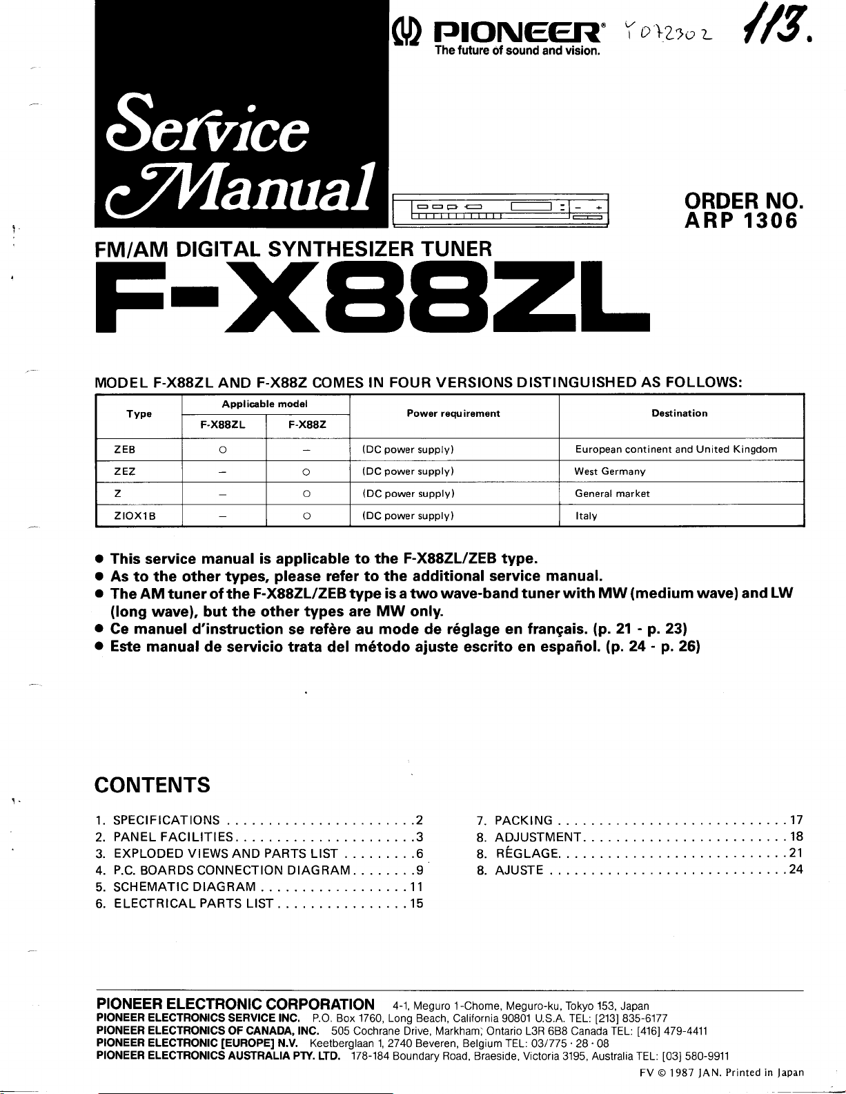
ORDER NO.
ARP 1306
FM/AM
DIGITAL SYNTHESIZER
TUNER
FIXBE|z;L
MODEL F-X88ZL AND F-X882
Type
ZEB o
zEz
Applicable model
F.X88ZL F-X882
o
z o
zroxl
B
o
This service
o
As to the other types,
o
The AM tuner
(long
wavel, but the other
Ce manuel
Este manual
o
o
manual is applicable to the
the F-XSSZLIZEB type
of
d'instruction se
de servicio trata del
o
please
types are MW only.
refire
COMES
IN FOUR VERSIONS
Powor
r€qu irement
(DC
power
supply)
(DC
power
supply) West
(DC
power
supply) General market
(DC
power
supply) Italy
F-XSSZLIZEB type.
refer to the additional
is a two wave'band tuner
mode
au
m6todo
r6glage en frangais.
de
ajuste escrito en espafiol.
DISTINGUISHED
European
service manual.
with MW
Germany
(p.
21
lp.
AS FOLLOWS:
Destination
continent and
(medium
-
p.
-
2a
United Kingdom
wave) and
231
p.
261
LW
CONTENTS
1.
SPECIFICAT|ONS
pANELFAcrLrrrES..
2.
EXPLODED VIEWS
3.
P.C.BOARDSCONNECTION
4.
5. SCHEMAT|CD|AGRAM....
ELECTRICALPARTSLIST..
6.
PIONEER
PIONEER
PIONEER
PIONEER
PIONEER
ELECTRONIC
ELECTRONICS
ELECTRONICS
ELECTRONIC
ELECTRONICS
:........... :.......3
PARTS
AND
CORPORATION
SERVICE lNC. P.O. Box 1760, Long Beach,
OF CANADA, lNC.
IEUROPEI
AUSTRALIA PW.
LIST . . . . . . . . .6
DIAGRAM.
505 Cochrane Drive, Markham) Ontario L3R 688 Canada TEL:
N.V. Keetberglaan 1,2740 Beveren, Belgium fEL:
LTD.
.......2
. . . . . . .9
.........11
....15
4-1,
Mesuro 1-chome, Meguro-ku, rokyo 153,
178-184
Boundary Road, Braeside, Victoria
PACKTNG
7.
ADJUSTMENT....
8.
REGLAGE.
8.
L
AJUSTE
California 90801 U.S.A. TEL:
03/775. 28 . 08
3195,
Japan
835-6177
[2]31
Australia TEL:
[416]
FV o.l 987
479-4411
580-9911
[03]
lAN.
........17
.....18
.......21
. . .24
Printed in
Japan
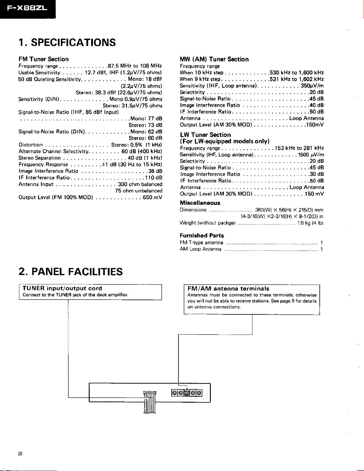
1. SPECIFICATIONS
FM
Tuner Section
Frequency range.
Usable
Sensitivity
50 dB Ouieting
Sensitivity
. . .
......12.7 dBf,
Sensitivity.
(DlN)....
. . . .
Stereo: 38.3
":'::*
:':1': :: ):':: ::T I
(DlN).
Signal-to-Noise
Distortion . . . . . . .
Alternate Channel Selectivity. .
Stereo Separation
Frequency Response
lmage Interference Ratio
lF Interlerence Ratio.
Antenna Input
Output Level
Ratio
(FM
. . .... .
. . . . . .
100%
....
MOD)
/75
175
MHz
ohms)
ohmsl
ohmsl
. .87.5 MHz to 108
(1.2!V/75
IHF
Mono: 18 dBf
l2.2ttY
dBf
l22.6ttv
Mono
. .
Stereo:3t.5gvl75 ohms
0.9pV/75 ohms
':1:'1
Mono, i7 dB
Stereo:
. . . .Mono:62
Stereo:60
Stereo:0.5%
. . .
.....40d8(lkHz)
dB
. . 300 ohm balanced
dB
60
(30
Hz
75 ohm unbalanced
73 dB
dB
d8
(1
kHz)
(400
kHz)
15 kHz)
to
...38dB
..110d8
. 650 mV
(AM)
MW
Frequency
When
When
S€nsitivity
Selectivity
Signal-to-NoiseRatio.... ..........45dB
lmage
lFlnterferenceRatio.... ..........50d8
Antenna. . . . . . . . Loop Antenna
OutputLevel{AM30%MOD) .......150mV
Tuner Section
range
kHz
10
9 kHz step . . . . . .531 kHz to 1,602 kHz
stsp. , . , .530 kHz to
(lHF,
Loopantenna). . .... . .. . . . 350!V/m
Interference Ratio
,., .....,..40d8
1,600
kHz
.....20d8
LW Tuner Section
(For
LW-equ
Frequencyrange....
Sensitivity
Selectivity
Signal-to-NoiseRatio....
Interference Ratio ... ........30d8
lmage
lF Interference Ratio . . . . ..........50dB
Antenna . , . , . . . Looo
Output Level
Miscellaneous
Dimensions
ipped models only)
...153kH2to281
(lHF,
Loop antenna) . . . . .1500
..........45d8
(AM
MOD)
30%
14-3116(W)
360(W)
x
x2-3l16(H) x
56(Hl x 215(D)
kHz
pVlm
....20dB
Antenna
mV
150
mm
8-1l2(D)
in
2. PANEL
FACILITIES
TUNER input/output
Connect lo the TUNER
iack
cord
of the deck amplitier.
Furnished Parts
FM T-type
AM
antenna
Loop Antenna
FM/AM antenna terminals
Antennas must
you
will not be able to receive stations. See
on antenna connections.
be connocted to those terminalsr otherwise
page
5 for
details
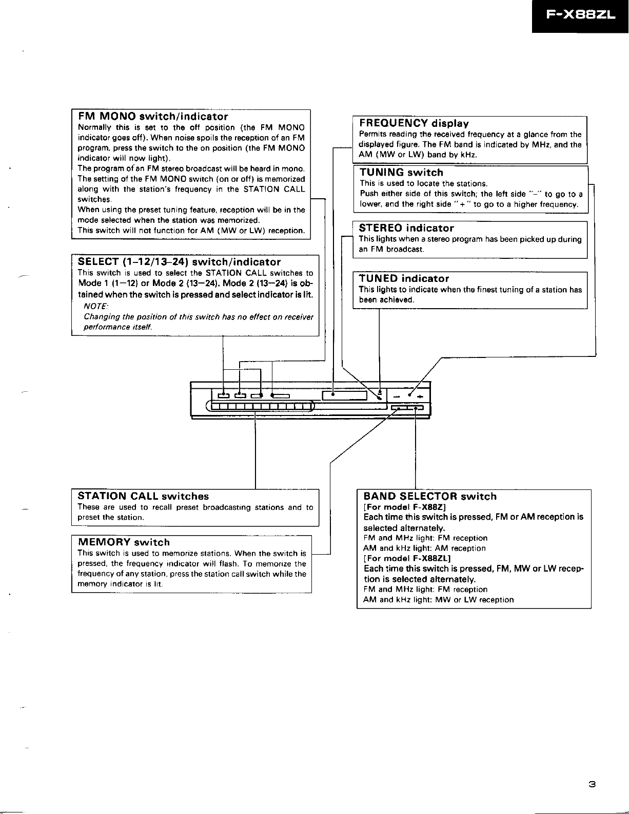
FM MONO
Normally this is
indicator
program, pr6Es
indicalor will now light).
program
The
The setting
along with the station's frequgncy in
swrtch9s.
When
using the
mode
selected wh6n lhe station
This
switch will nol function tor AM
SELECT
This
switch is
Mode 1
tained
when tho switch is
switch
go€s
(1-12)
set to the off
off). When noise spoils the reception
the switch to the on
FM
ofan
FM MONO
of tho
preset
-1
(1
2
11
used to s6l€ct th6 STATION CALL switches to
or Mode
ind icato
/
position (the
position (the
stereo broadcast will be heard in mono.
tuning feature, reception will be in the
swrtch
was
(on
memorized.
(MW
3-241 switch/indicator
(13-24).
2
oressed 8nd
NOTE:
Changing the
peiomance
position
itself.
this
ol
switch has no ellect on rcceivet
r
FIV MONO
of an
Fl\4 MoNo
or off) is momorized
the STATION
LW) reception.
or
Mode 2
select indicator i8 lit.
CALL
(13-24)
FM
is
ob-
FREOUENCY
Pormits roading
display6d figris. The FM
(MW
AM
or
TUNING
This is used to locate
Push
either side of
lower,
and the right side
display
received
thg
LW)
band by kHz.
switch
the stations.
this switch; the left side
STEREO indicator
This lights wh6n
FM
an
broadcast.
a stereo
TUNED indicator
This lights
b6en achieved.
indicate wh€n
to
frequency at a
indicated
band is
" + "
go
to
program
finost
the
glance
trom lhe
by MHz, and the
"-"
picked
to
up during
to a higher lrequency.
has been
tuning of a station has
go
to a
STATION
These
preset
MEMORY
This
switch
pressed,
frequency
memory indicalor
CALL switches
are used
the statton.
to
switch
is
used to memorize
frequency
the
of any
station,
preset
recall
indicator will flash. To memorize the
press
is lit.
broadcasting stations and to
stations.
the station call switch while rhe
When
the switch
BAND
IFor
Each time this switch is
SELECTOR switch
modol
F-X882]
pressed,
FM or AM reception is
selected alternately,
FM
and MHz
is
AM and kHz light: AM reception
model F-X88ZLl
lFor
Each time this switch is
tion is selected
FM
and
AM
and kHz
lightr
FM reception
slternatelv.
MHz light: FM
light:
MW or LW reception
pressed,
reception
FM, MW or LW recep-
3
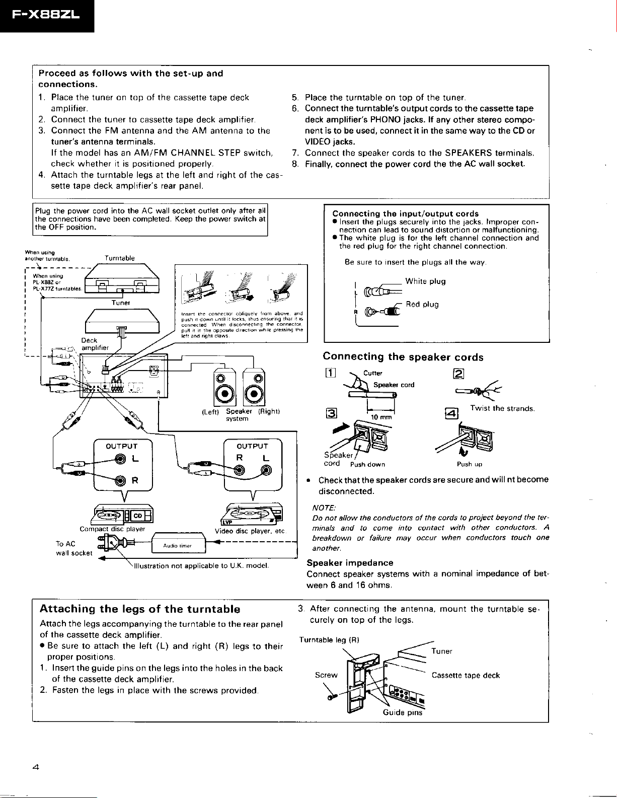
Proceed
tollows with
as
the set-up and
connections,
1. Place the tuner on top of the
amplifier.
2. Connect the tuner to
Connect
3.
the
FM
cassette tape deck amplifier.
antenna and the
cassette tape deck 5.
6.
AM
antenna to the nent is to be used, connect it in the same way to the CD or
Connectthe turntable's output
deck
tuner's antenna terminals. VIDEO
lf
model has
the
check whether il is
4. Attach
the turntable
sette tape deck amplifiers rear
an AM/FM CHANNEL STEP swirch, 7. Connect the speaker cords lo the SPEAKERS terminals.
posilioned properly.
legs
at the
left
and
right
ol the cas
L Finally, connect the
panel.
Place
the turntable on top of the tuner.
amplitier's
PHONO
jacks.
jacks.
power
cords to the cassette
lf
any other stereo compo-
cord the
the AC wall socket.
tape
Plug the
the
connections
the OFF
power
cord into the AC wall socket outlet only after all
have been
position.
completed.
Keep the
(Left) Sp€aker
power
Video disc
switch at
play€..
(Righ0
etc
Connecting tho input/output cords
a
Inserl the
nectaon
a
The
the
Be sure
white
pl'rg
red
plugs
can
to
securely
lead
to sound drsto(ion or
plug
is for the left channel connection and
{or
fight
the
insert
plugs
the
White
mi#
plug
Red
eod
Connecting
.
Check that the
disconnected.
NOTE:
Do not allow
minals and to come into contact
brcakdown or failurc may occur
the
speaker cords arc
the
conductors
of the cods
jacks.
into
the
channel connectron.
all the
plug
secure and will
with other conductors.
when conductots
lmpfoper
malfunctioning.
way.
prciect
to
beyond the ter-
con-
strands.
nt become
A
touch one
Attaching
Attach
the legs accompanying
ot the
cassette deck amDlifier.
.
Be
sure lo attach
the legs
proper posnons.
1 . Insen
ot the
2. Fasten
guide pins
the
cassette deck amplitier.
the legs in
lllustration
not aeolicable to U.K.
of the turntable
the turntable to the rear
(L)
left
the
on the
place
and righr
legs into
with the screws
model.
(R)
legs
to their
the holes in the
provided.
panel
back
Speakel
Connect
ween 6 and 16 ohms.
impedance
speaker systems
with a nominal
3. After connecting the antenna,
curely on top ot the legs.
Turntable
leg
(Rl
impedance of bet-
mount the
turntable se-
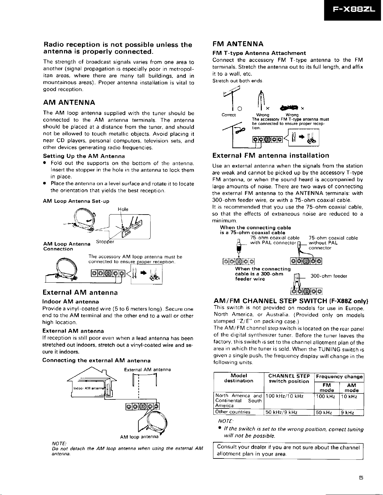
Radio
antenna is
The strength of
another
itan
mountainous
good
reception is not
properly
broadcast signals varies from
(signal propagation
areas, where
reception.
there are many
areas). Proper
connected.
AM ANTENNA
The AM loop
connected to
should
not
be
allowed to touch metallic
near
CD
other devices
Setting Up
.
Fold
Insert
In
Dlace.
.
Place
lhe
orientation that
AM Loop Antenna
AM
Loop Antenna
Conn€ction
antenna supplied with
AM
the
placed
be
players, personal
out the supports
the stopper in
the antenna on a level
at a distance trom
generating
the AM Antenna
The
connecled to enSure
antenna terminals. The
computers, television sets,
radto frequencies.
on the bottom of the
hole in
the
yields
Set-up
accessory AM loop
ryf,:c
External AM
Indoor AM
Provide
end to the AM
high location.
External
lf reception
stretched out indoors, stretch
cure it indoors.
Connecting
a vinyl-coated
AM antenna
anten na
antenna
(5
wire
terminal and the
poor
is still
the
even when a lead
external AM antenna
possible
is
especially
tall buildings, and in
antenna installation is vital
objects.
the antenna to lock
surlace and rotale it to locate
the
best
proper
f ----
to 6 meters long).
other end to a wall or olher
out a vinyl-coated wire
unless the
one area to
poor
in metropol-
the tuner should be
antenna
the tuner, and should
placing
Avoid
antenna.
them
receptron.
antenna must be
receplton
t]]]
Secure one
antenna has been
and se-
to
and
FM ANTENNA
FM T-type Antenna Attachment
Connect the accessory FM T-type antenna to the FM
terminals. Stretch the antenna out to its full
it
wall,
to a
Stretch
"-V a
Cored
-17
it
External FM
Use an external antenna when the signals
are weak and cannol be
FM
antenna, or when the sound
large amounts oI noise. There are lwo ways of connecting
the external
300-ohm
It is recommended
so that the effects of extraneous noise are reduced to a
minimum.
When th€ connecting
is a 75-ohm
@@(@@f@l
AM/FM
This
North
stamped
The AM/FM
of the
tactory,
area in
given
following
etc.
out both ends.
',1
t ill
|
,..-
I
Ir|L:l
feeder
^
A_
I K
Y t-\
lrl
|
Wong
The accessorv FM T-tyDe antsnna musl
be connected ro ensure
*"
AlF
tOOCIron( tl
antenna
picked
FM
antenna to the
wire, or with a 75-ohm coaxial cable.
you
that
coaxial cable
75 ohm
wrth PAL.onnector
cable
coaxial cable 75-ohm coaxial cable
'
Wrong
proper
t.;_
'lrq
installation
up by the accessory T-type
heard is
ANTENNA
use the
[L_
@16l@16l@l
When
the connocting
cable is a 300-ohm
t€eder wrre
CHANNEL STEP SWITCH
switch is not
America,
"Z/E"
digital synthesizef
this switch is
which the tuner is
a single
units.
provided
or Australia.
packing
on
channel
step switch
set to
push,
the frequency
n.Tl 3oo.ohm
/,{-
dIA
,-,*l@D[@T@l
on models lor
(Provided
case.)
is located
tuner. Before
the channel
sold.
When
display
length,
rscep-
-
trom the
accompanied bV
terminals:
75-ohm
w'thout PAL
connecror
the TUN ING
coaxial cable,
teeder
(F-x882
use in
only on models
on the rear
the tuner leaves
allotment
plan
will change in
and alfix
station
with
only)
Europe,
panel
the
ot the
switch is
the
NOTE:
Do not detach
the AM loop antenna
when using the extenal AM
Model
d€stination
No(h
Ameflca
Conlinental
America
Olher countries
NOTE
.
lf the
will not
Consult
allotment
Soulh
switch is
be
your
olan
CHANNEL
switch
and
100
kHz/10
50 kHz/g kHz
set to the wrong
possible.
dealer if
you
in
vour area.
STEP
position
kHz 100
are not
Frequsncy
FM
modeAMmoo€
kHz 10 kHz
50 kHz
position,
sure about
change
9 kHz
coftect tunjng
the channel
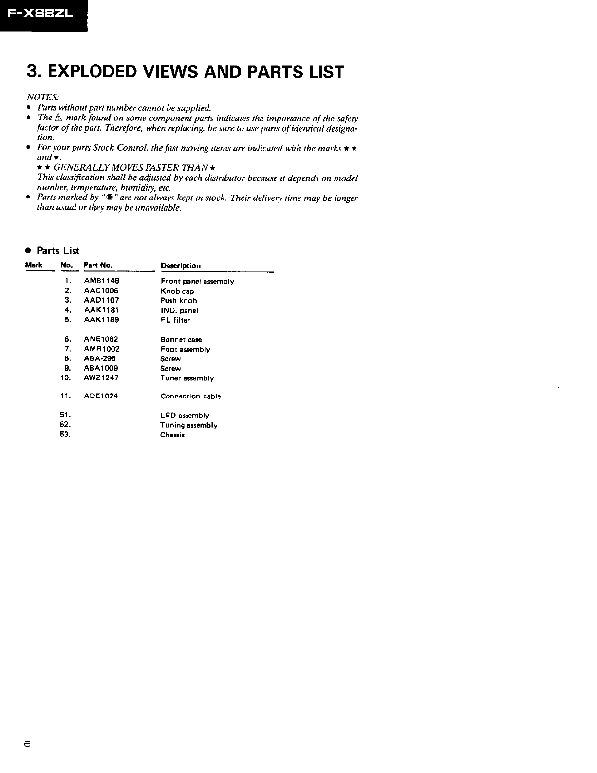
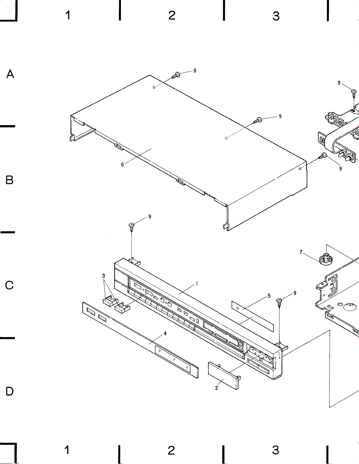
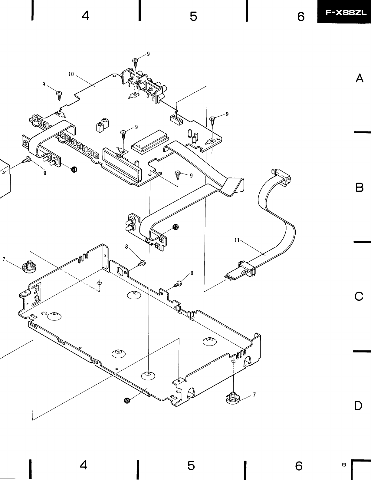
3. EXPLODED
VIEWS AND
NOTES:
.
Pats without
o
The
A
factor
mark
of the
part
number cannot be supplied.
on some component
found
part.
Therefore, when replacing,
On.
o
your parts
For
*.
and
* *
GENERALLY MOVES
This classification
number,
c
Parts
marked
than usual or thev
.
hrts List
Mlrk No, Parl
Stock
temperuture,
by
"A"
mav be unavailable.
No.
1.
AMB1146
AACr006
AAD1,I07
4.
AAKl181
AAK1189
ControL the
FASTER THAN
shall be
adjusted by each distributor
humidiry, etc
are not always kept
moing items
fast
D.ac.iptio|i
psn6lassombly
Front
Knob cap
Pu3h
knob
pan6l
lND.
r-
L l t€r
PARTS LIST
parts
indicqtes the importance of
be sure to use
*
in stock. Their delivery
parts
qre
indicated with the marks
because it depends on
identicol
of
designa-
* *
model
time may be longer
the sofety
7,
10.
11.
ANE1062
AMRIOO2
A8A-298
ABAlOO9
AW21247
ADE t O24
Bonnet csse
Foot
€ssembly
Scr6w
Scrow
Tun€r sasombly
Connection
LED a$embly
Tuning
Chassis
cable
assembly
6
A
B
1
2
3
C
D
1
2
3
4
5
A
B
I
4
5
6
c
D
"[-
 Loading...