


FH-P800BT/XJ
Pioneer FH-P800BT/XJ, FH-P8000BT, FH-P80BT, FH-P80BT/XJ, FH-P80BT/UC Service Manual
...
PIONEER CORPORATION 4-1, Meguro 1-chome, Meguro-ku, Tokyo 153-8654, Japan
PIONEER ELECTRONICS (USA) INC. P.O. Box 1760, Long Beach, CA 90801-1760, U.S.A.
PIONEER EUROPE NV Haven 1087, Keetberglaan 1, 9120 Melsele, Belgium
PIONEER ELECTRONICS ASIACENTRE PTE. LTD. 253 Alexandra Road, #04-01, Singapore 159936
PIONEER CORPORATION 2008
CD RECEIVER
ORDER NO.
CRT4134
FH-P800BT/XJ/UC
FH-P800BT
FH-P8000BT
CD RDS RECEIVER
FH-P80BT
CD RECEIVER
/XJ/EW5
FH-P6050UB
This service manual should be used together with the following manual(s):
Model No. Order No. Mech.Module Remarks
CX-3240 CRT4050 S10.5COMP2-
iPod/USB
CD Mech. Module : Circuit Descriptions, Mech. Descriptions, Disassembly
/XJ/UC
/XJ/ES
/XJ/UC
FH-P800BT/XJ/UC
For details, refer to "Important Check Points for Good Servicing".
K-ZZZ. FEB. 2008 Printed in Japan
1234
1234
C
D
F
A
B
E
SAFETY INFORMATION
- Safety Precautions for those who Service this Unit.
When checking or adjusting the emitting power of the laser diode exercise caution in order to get safe, reliable
results.
Caution:
1. During repair or tests, minimum distance of 13 cm from the focus lens must be kept.
2. During repair or tests, do not view laser beam for 10 seconds or longer.
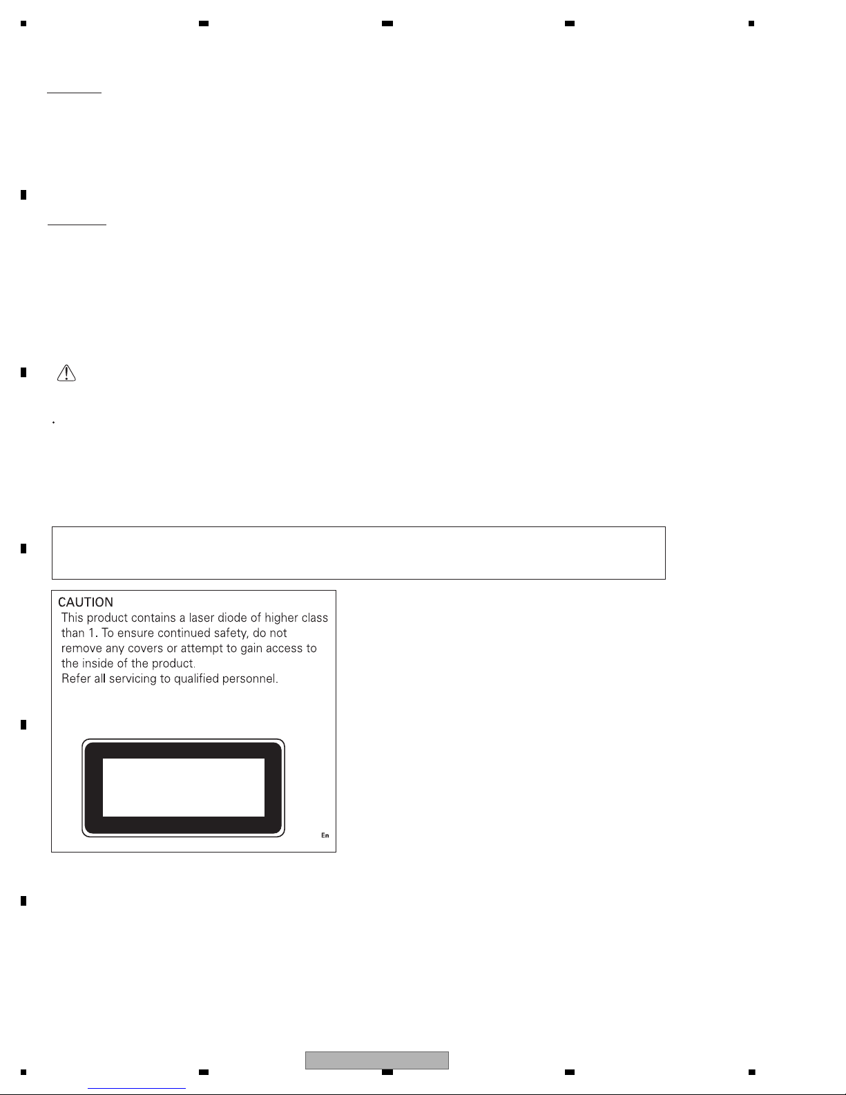
CAUTION:
USE OF CONTROLS OR ADJUSTMENTS OR PERFORMANCE OF PROCEDURES OTHER THAN THOSE
SPECIFIED HEREIN MAY RESULT IN HAZARDOUS RADIATION EXPOSURE.
CLASS 1
LASER PRODUCT
Where in a manufacturer’s service documentation, for example in circuit diagrams or lists
of components, a symbol is used to indicate that a specific component shall be replaced only
by the component specified in that documentation for safety reasons, the following symbol shall
be used:
CAUTION
This service manual is intended for qualified service technicians; it is not meant for the casual do-it-yourselfer.
Qualified technicians have the necessary test equipment and tools, and have been trained to properly and safely repair
complex products such as those covered by this manual.
Improperly performed repairs can adversely affect the safety and reliability of the product and may void the warranty.
If you are not qualified to perform the repair of this product properly and safely, you should not risk trying to do so
and refer the repair to a qualified service technician.
WARNING
This product contains lead in solder and certain electrical parts contain chemicals which are known to the state of
California to cause cancer, birth defects or other reproductive harm.
Health & Safety Code Section 25249.6 - Proposition 65
2
FH-P800BT/XJ/UC
5678
56
7
8
C
D
F
A
B
E
WARNING!
The AEL (accessible emission level )of the laser power output is less than CLASS 1
but the laser component is capable of emitting radiation exceeding the limit for
CLASS 1.
A specially instructed person should do servicing operation of the apparatus.
Laser diode characteristics
Wave length : 785 nm to 814 nm
Maximum output : 1 190 W(Emitting period : unlimited)
Additional Laser Caution
Transistors Q101 in PCB drive the laser diodes.
When Q101 is shorted between their terminals, the laser diodes will radiate beam.
If the top cover is removed with no disc loaded while such short-circuit is continued,
the naked eyes may be exposed to the laser beam.
CAUTION
Danger of explosion if battery is incorrectly replaced.
Replaced only with the same or equivalent type recommended by the manufacture.
Discord used batteries according to the manufacture's instructions.
FH-P800BT/XJ/UC
3
1234
1234
C
D
F
A
B
E
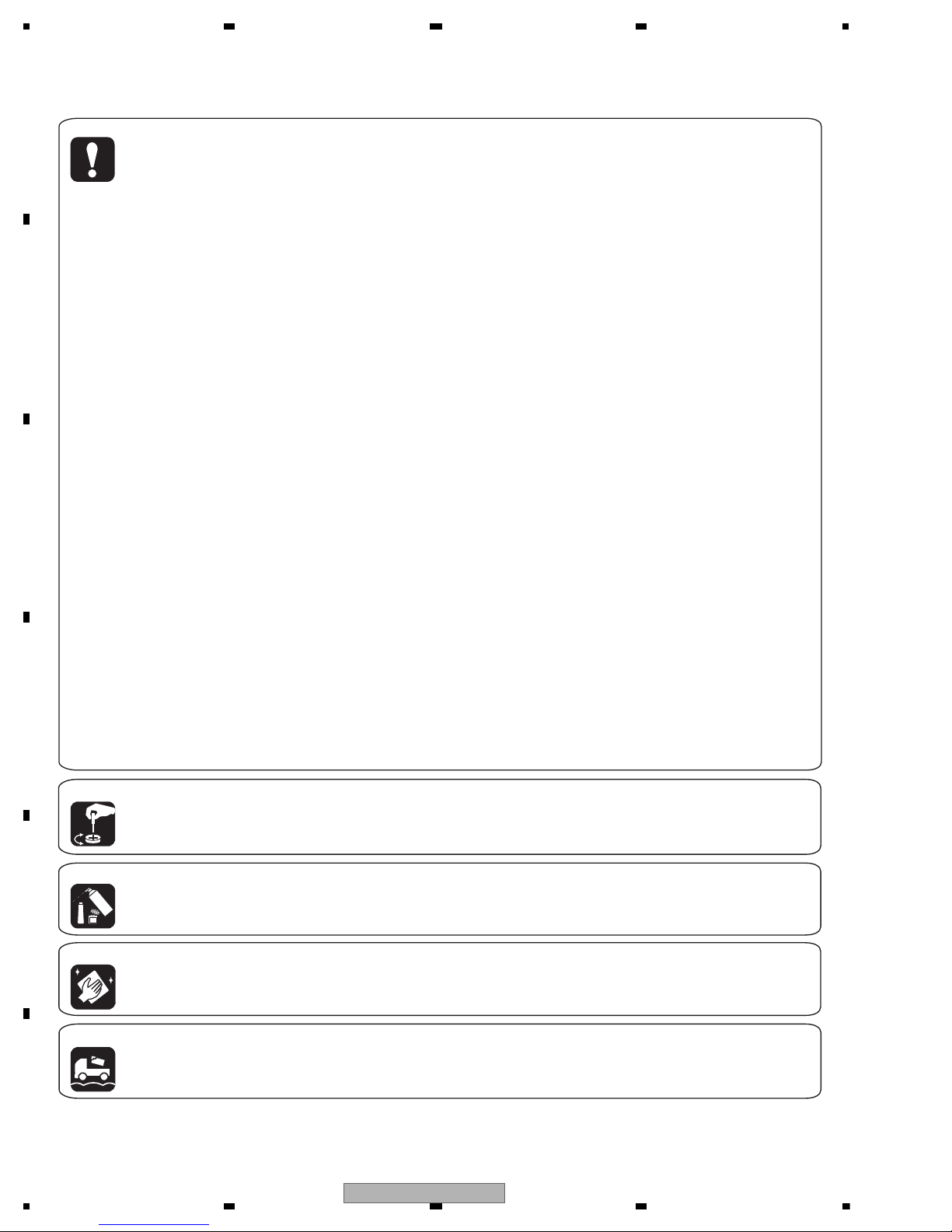
[Important Check Points for Good Servicing]
In this manual, procedures that must be performed during repairs are marked with the below symbol.
Please be sure to confirm and follow these procedures.
1. Product safety
Please conform to product regulations (such as safety and radiation regulations), and maintain a safe servicing environment by
following the safety instructions described in this manual.
1 Use specified parts for repair.
Use genuine parts. Be sure to use important parts for safety.
2 Do not perform modifications without proper instructions.
Please follow the specified safety methods when modification(addition/change of parts) is required due to interferences such as
radio/TV interference and foreign noise.
3 Make sure the soldering of repaired locations is properly performed.
When you solder while repairing, please be sure that there are no cold solder and other debris.
Soldering should be finished with the proper quantity. (Refer to the example)
4 Make sure the screws are tightly fastened.
Please be sure that all screws are fastened, and that there are no loose screws.
5 Make sure each connectors are correctly inserted.
Please be sure that all connectors are inserted, and that there are no imperfect insertion.
6 Make sure the wiring cables are set to their original state.
Please replace the wiring and cables to the original state after repairs.
In addition, be sure that there are no pinched wires, etc.
7 Make sure screws and soldering scraps do not remain inside the product.
Please check that neither solder debris nor screws remain inside the product.
8 There should be no semi-broken wires, scratches, melting, etc. on the coating of the power cord.
Damaged power cords may lead to fire accidents, so please be sure that there are no damages.
If you find a damaged power cord, please exchange it with a suitable one.
9 There should be no spark traces or similar marks on the power plug.
When spark traces or similar marks are found on the power supply plug, please check the connection and advise on secure
connections and suitable usage. Please exchange the power cord if necessary.
a Safe environment should be secured during servicing.
When you perform repairs, please pay attention to static electricity, furniture, household articles, etc. in order to prevent injuries.
Please pay attention to your surroundings and repair safely.
2. Adjustments
To keep the original performance of the products, optimum adjustments and confirmation of characteristics within specification.
Adjustments should be performed in accordance with the procedures/instructions described in this manual.
4. Cleaning
For parts that require cleaning, such as optical pickups, tape deck heads, lenses and mirrors used in projection monitors, proper
cleaning should be performed to restore their performances.
3. Lubricants, Glues, and Replacement parts
Use grease and adhesives that are equal to the specified substance.
Make sure the proper amount is applied.
5. Shipping mode and Shipping screws
To protect products from damages or failures during transit, the shipping mode should be set or the shipping screws should be
installed before shipment. Please be sure to follow this method especially if it is specified in this manual.
4
FH-P800BT/XJ/UC

5678
56
7
8
C
D
F
A
B
E
CONTENTS
SAFETY INFORMATION .....................................................................................................................................2
1. SERVICE PRECAUTIONS................................................................................................................................6
1.1 SERVICE PRECAUTIONS.........................................................................................................................6
1.2 NOTES ON SOLDERING...........................................................................................................................6
2. SPECIFICATIONS.............................................................................................................................................7
2.1 SPECIFICATIONS ......................................................................................................................................7
2.2 DISC/CONTENT FORMAT.........................................................................................................................9
2.3 PANEL FACILITIES...................................................................................................................................10
2.4 CONNECTION DIAGRAM........................................................................................................................16
3. BASIC ITEMS FOR SERVICE........................................................................................................................20
3.1 CHECK POINTS AFTER SERVICING .....................................................................................................20
3.2 PCB LOCATIONS .....................................................................................................................................21
3.3 JIGS LIST.................................................................................................................................................22
3.4 CLEANING ...............................................................................................................................................22
4. BLOCK DIAGRAM ..........................................................................................................................................24
5. DIAGNOSIS ....................................................................................................................................................26
5.1 OPERATIONAL FLOWCHART.................................................................................................................26
5.2 ERROR CODE LIST.................................................................................................................................27
5.3 CONNECTOR FUNCTION DESCRIPTION .............................................................................................29
6. SERVICE MODE.............................................................................................................................................30
6.1 CD TEST MODE.......................................................................................................................................30
6.2 DISPLAY TEST MODE.............................................................................................................................32
6.3 BLUETOOTH TEST MODE ......................................................................................................................33
7. DISASSEMBLY ...............................................................................................................................................37
8. EACH SETTING AND ADJUSTMENT............................................................................................................42
8.1 CHECKING THE GRATING AFTER CHANGING THE PICKUP UNIT ....................................................42
8.2 PCL OUTPUT CONFIRMATION...............................................................................................................44
9. EXPLODED VIEWS AND PARTS LIST ..........................................................................................................46
9.1 PACKING ..................................................................................................................................................46
9.2 EXTERIOR(1)...........................................................................................................................................50
9.3 EXTERIOR(2)...........................................................................................................................................54
9.4 CD MECHANISM MODULE.....................................................................................................................56
10. SCHEMATIC DIAGRAM................................................................................................................................58
10.1 OVERALL CONNECTION DIAGRAM(GUIDE PAGE) ............................................................................58
10.2 KEYBOARD UNIT ..................................................................................................................................64
10.3 CD MECHANISM MODULE(GUIDE PAGE)...........................................................................................66
10.4 BLUETOOTH UNIT.................................................................................................................................72
10.5 WAVEFORMS.........................................................................................................................................74
11. PCB CONNECTION DIAGRAM....................................................................................................................78
11.1 COMBI PWB UNIT .................................................................................................................................78
11.2 KEYBOARD UNIT ..................................................................................................................................82
11.3 CD CORE UNIT(S10.5COMP2-iPod-C2)...............................................................................................84
11.4 BLUETOOTH UNIT.................................................................................................................................86
11.5 ANTENNA UNIT .....................................................................................................................................88
12. ELECTRICAL PARTS LIST...........................................................................................................................89
FH-P800BT/XJ/UC
5

1234
1234
C
D
F
A
B
E
1. SERVICE PRECAUTIONS
1. You should conform to the regulations governing
the product (safety, radio and noise, and other
regulations), and should keep the safety during
servicing by following the safety instructions
described in this manual.
2. Before disassembling the unit, be sure to turn off
the power. Unplugging and plugging the connectors
during power-on mode may damage the ICs inside
the unit.
3. To protect the pickup unit from electrostatic discharge
during servicing, take an appropriate treatment
(shorting-solder) by referring to "the DISASSEMBLY".
4. After replacing the pickup unit, be sure to check the
grating.
5. Be careful in handling ICs. Some ICs such as MOS
type are so fragile that they can be damaged by
electrostatic induction.
Display of mis-installing CD mechanism
This machine is an installing model of S10.5COMP2-iPod-C2 mechanism.
When you install the S10.5COMP2-USB mechanism by mistake
It becomes the following error display by the CDS USB source.
CHK CDCORE
For environmental protection, lead-free solder is used on the printed circuit boards mounted in this unit.
Be sure to use lead-free solder and a soldering iron that can meet specifications for use with lead-free solders for repairs
accompanied by reworking of soldering.
Compared with conventional eutectic solders, lead-free solders have higher melting points, by approximately 40 C.
Therefore, for lead-free soldering, the tip temperature of a soldering iron must be set to around 373 C in general, although
the temperature depends on the heat capacity of the PC board on which reworking is required and the weight of the tip of
the soldering iron.
Compared with eutectic solders, lead-free solders have higher bond strengths but slower wetting times and higher melting
temperatures (hard to melt/easy to harden).
The following lead-free solders are available as service parts:
Parts numbers of lead-free solder:
GYP1006 1.0 in dia.
GYP1007 0.6 in dia.
GYP1008 0.3 in dia.
1.1 SERVICE PRECAUTIONS
1.2 NOTES ON SOLDERING
6
FH-P800BT/XJ/UC
5678
56
7
8
C
D
F
A
B
E
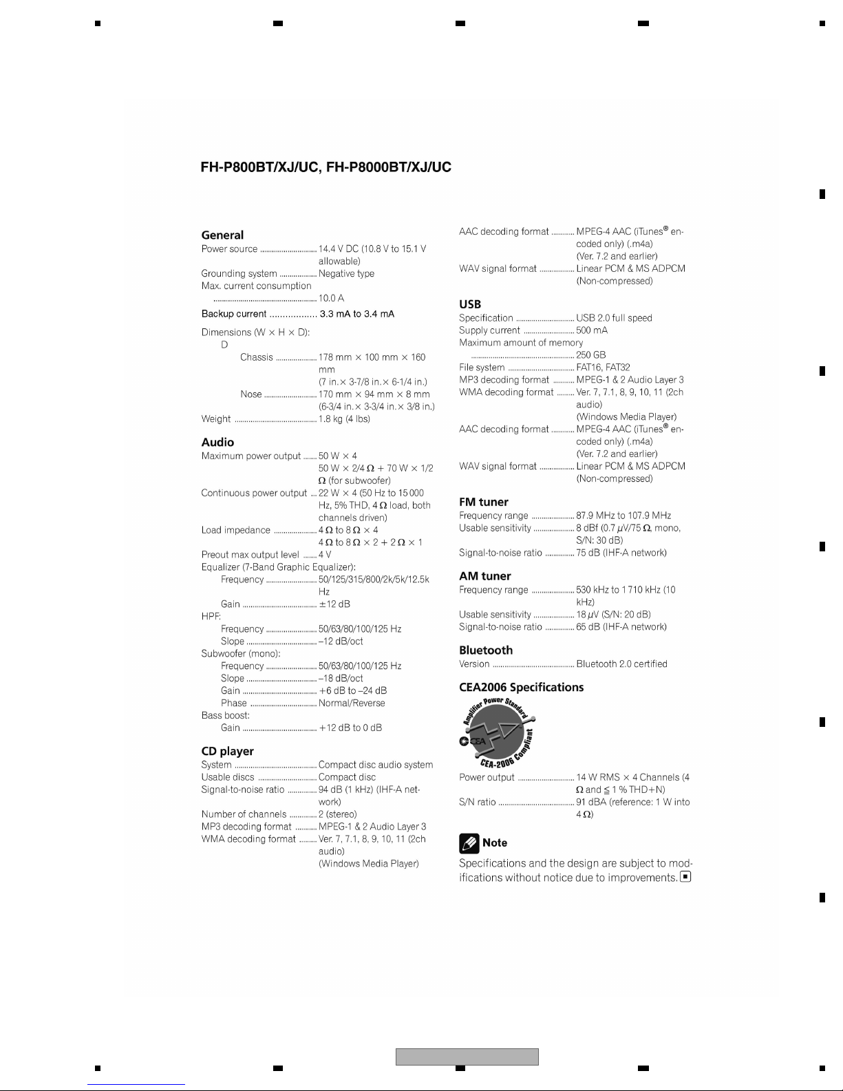
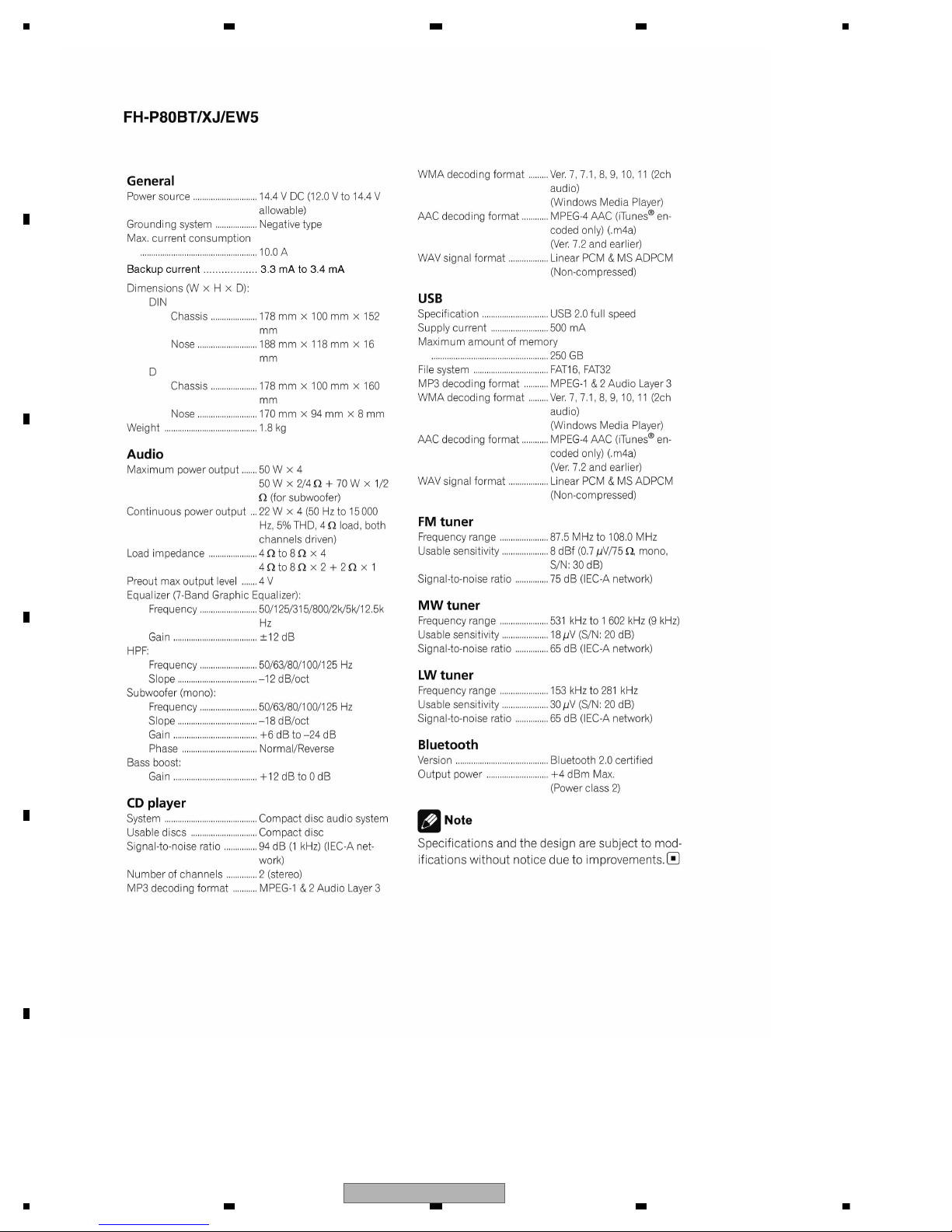
2. SPECIFICATIONS
2.1 SPECIFICATIONS
FH-P800BT/XJ/UC
7
1234
1234
C
D
F
A
B
E
8
FH-P800BT/XJ/UC

5678
56
7
8
C
D
F
A
B
E
The Bluetooth word mark and logos are owned by the Bluetooth SIG, Inc.
and any use of such marks by Pioneer Corporation is under license.
Other trademarks and trade names are those of their respective owners.
2.2 DISC/CONTENT FORMAT
FH-P800BT/XJ/UC
9
1234
1234
C
D
F
A
B
E
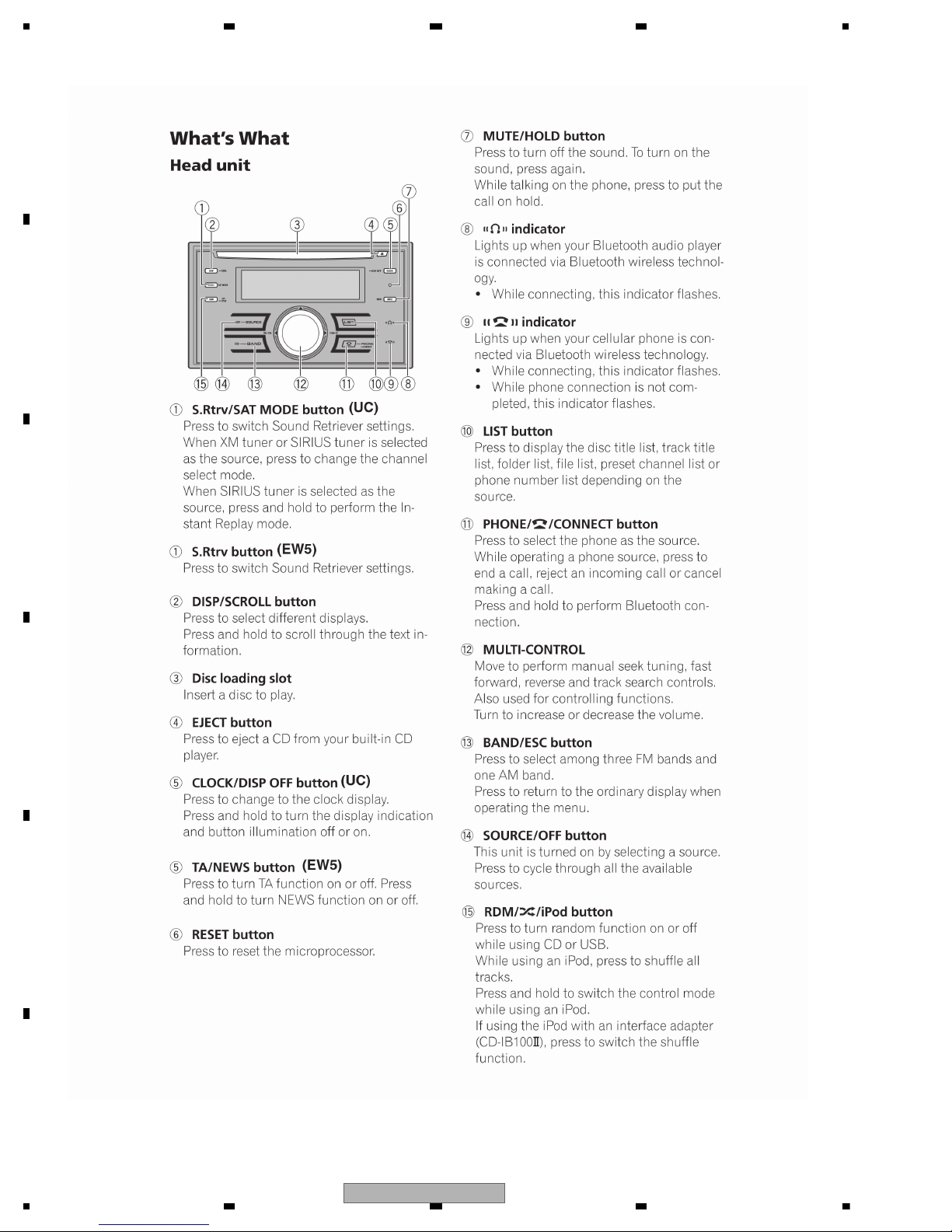
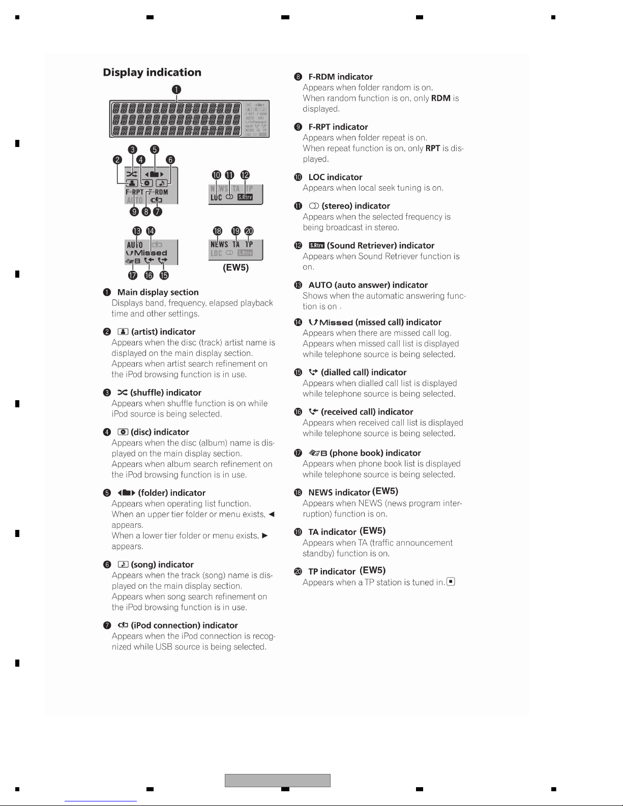
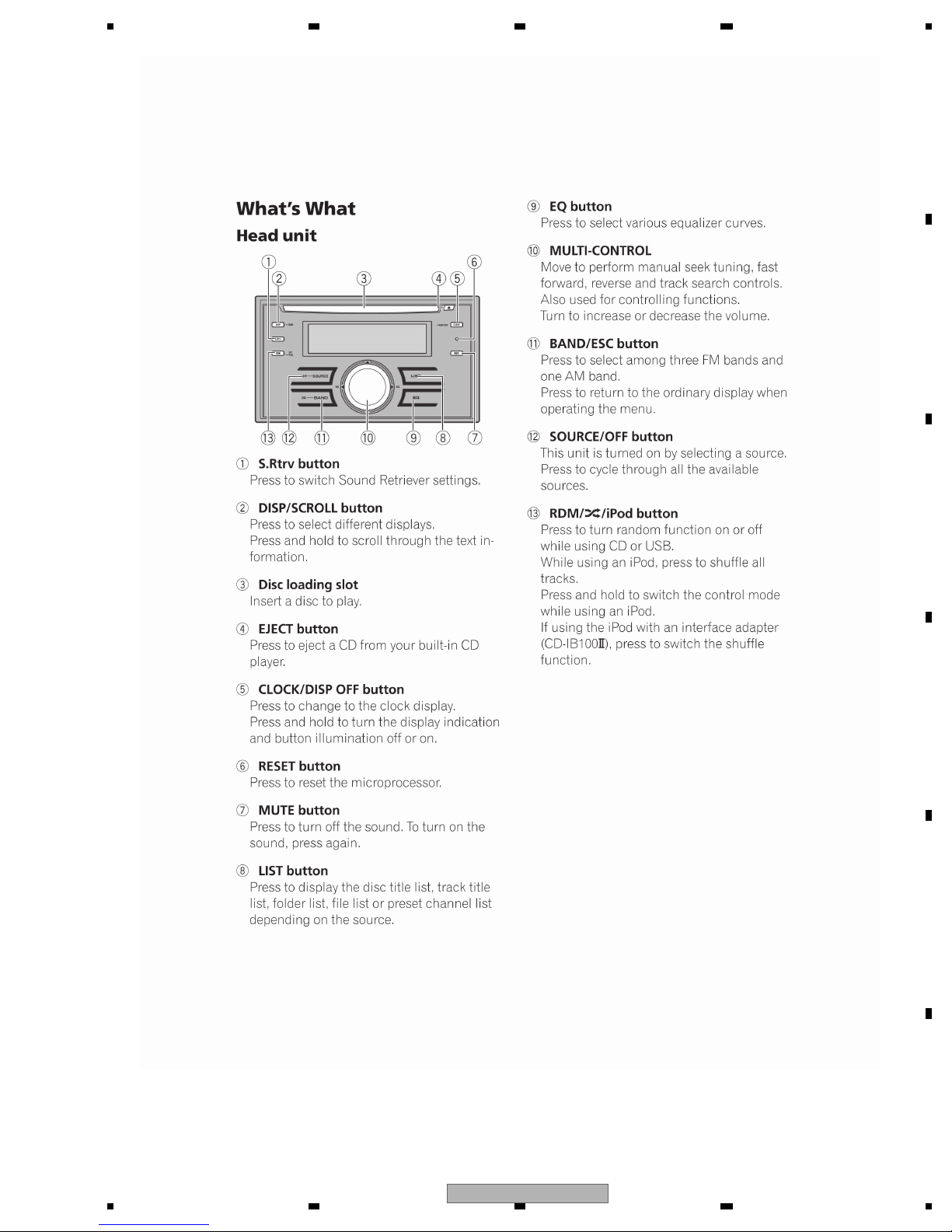
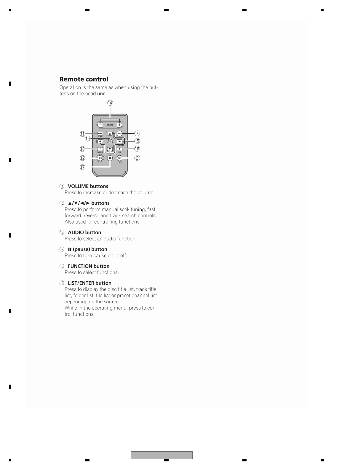
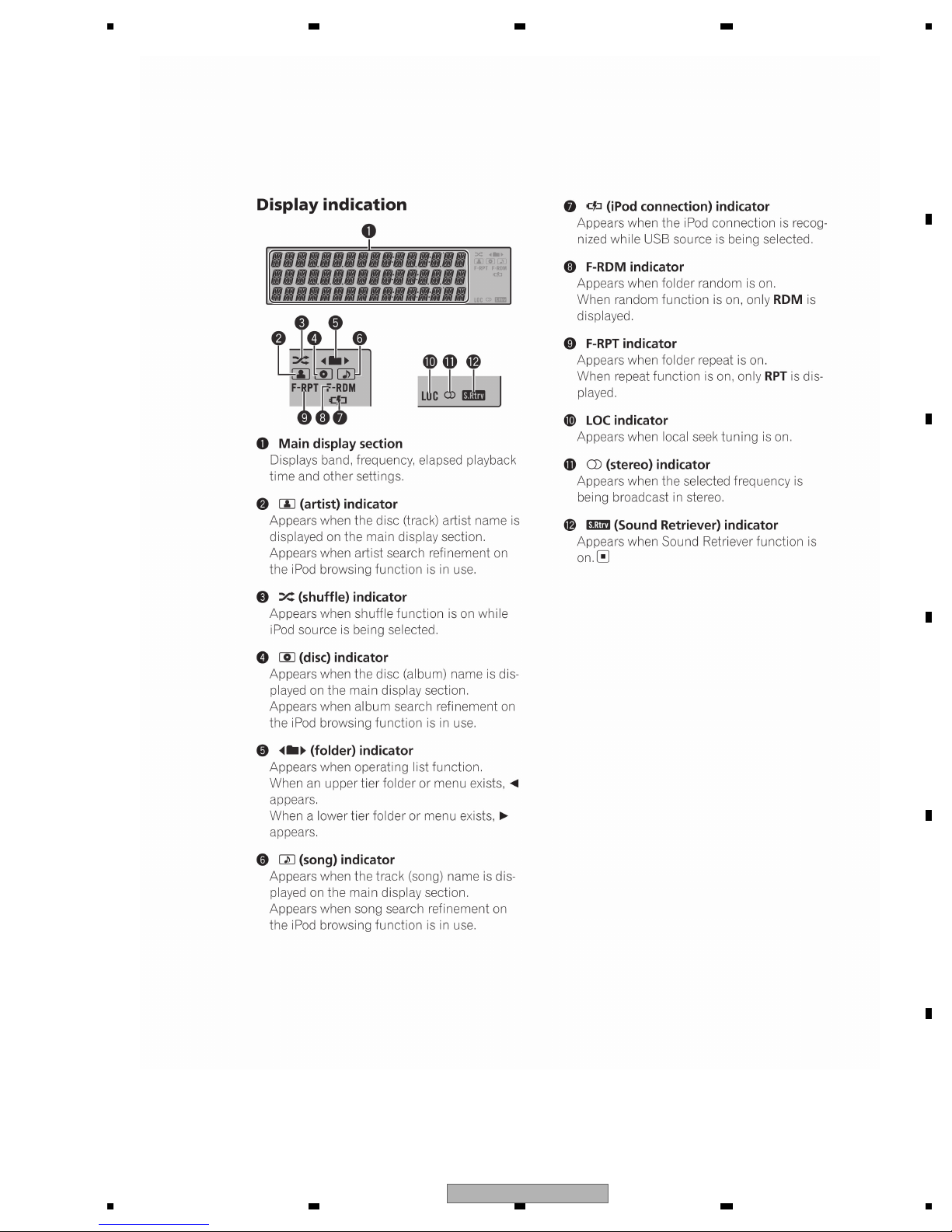
2.3 PANEL FACILITIES
FH-P800BT/XJ/UC, FH-P8000BT/XJ/UC, FH-P80BT/XJ/EW5
10
FH-P800BT/XJ/UC

5678
56
7
8
C
D
F
A
B
E
FH-P800BT/XJ/UC, FH-P8000BT/XJ/UC, FH-P80BT/XJ/EW5
FH-P800BT/XJ/UC
11
1234
1234
C
D
F
A
B
E
FH-P800BT/XJ/UC, FH-P8000BT/XJ/UC, FH-P80BT/XJ/EW5
12
FH-P800BT/XJ/UC
5678
56
7
8
C
D
F
A
B
E
FH-P6050UB/XJ/ES
FH-P800BT/XJ/UC
13
1234
1234
C
D
F
A
B
E
FH-P6050UB/XJ/ES
14
FH-P800BT/XJ/UC
5678
56
7
8
C
D
F
A
B
E
FH-P6050UB/XJ/ES
FH-P800BT/XJ/UC
15
1234
1234
C
D
F
A
B
E
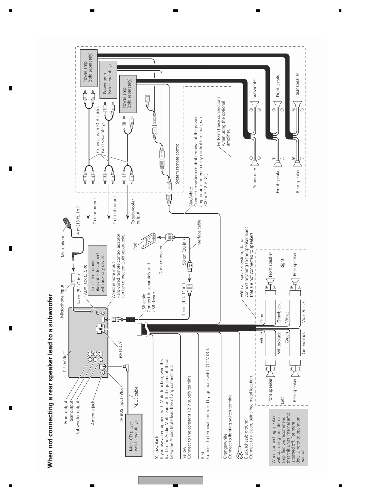
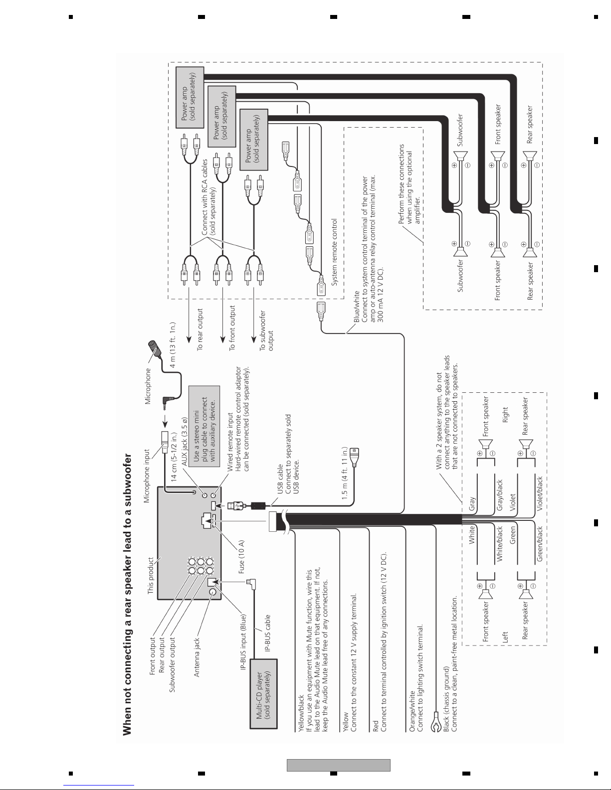
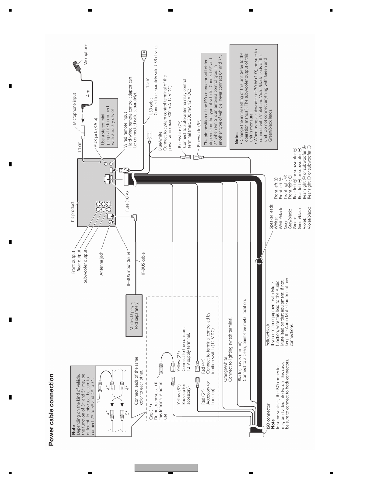
2.4 CONNECTION DIAGRAM
FH-P800BT/XJ/UC
16
FH-P800BT/XJ/UC
5678
56
7
8
C
D
F
A
B
E
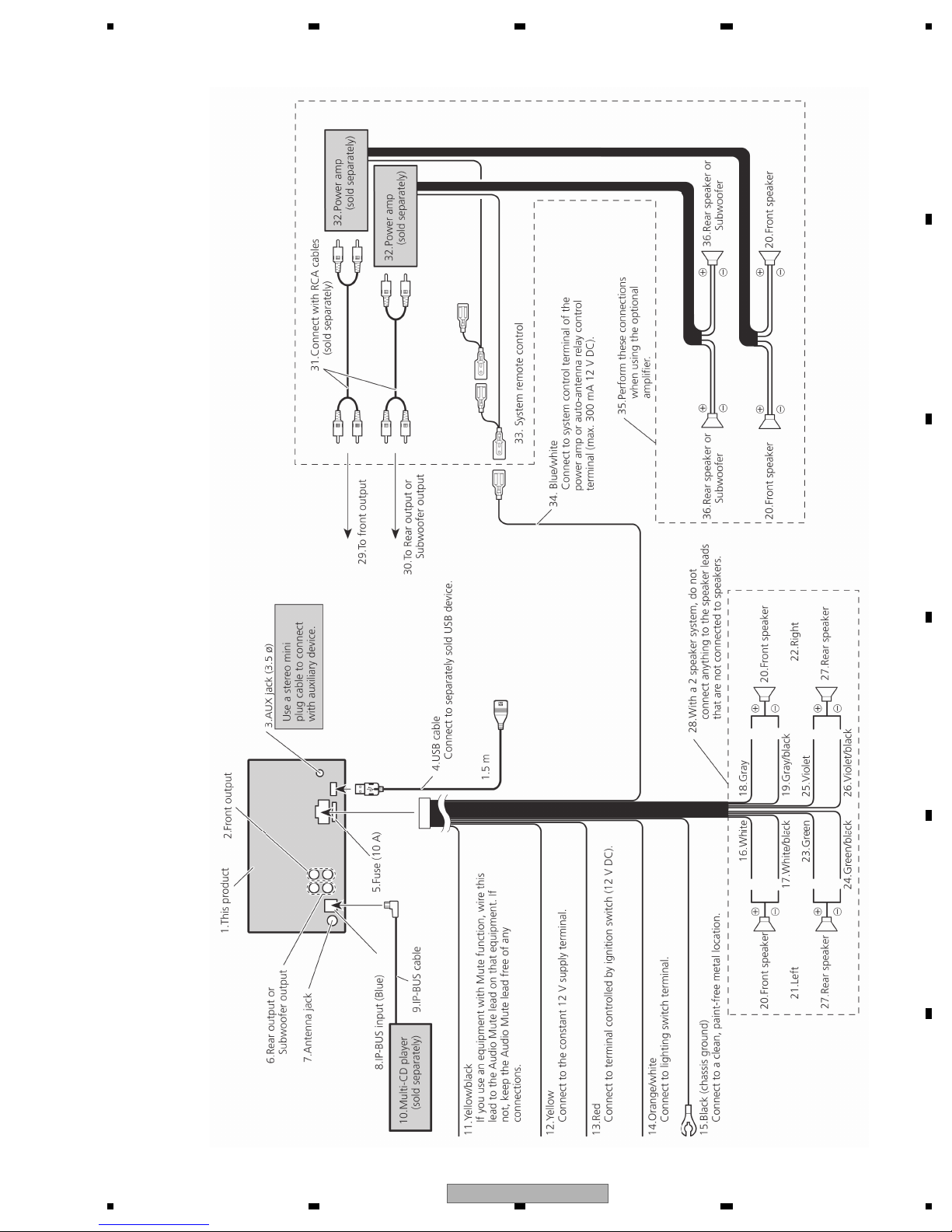
FH-P8000BT/XJ/UC
FH-P800BT/XJ/UC
17
1234
1234
C
D
F
A
B
E
FH-P80BT/XJ/EW5
18
FH-P800BT/XJ/UC
5678
56
7
8
C
D
F
A
B
E
FH-P6050UB/XJ/ES
FH-P800BT/XJ/UC
19
1234
1234
C
D
F
A
B
E
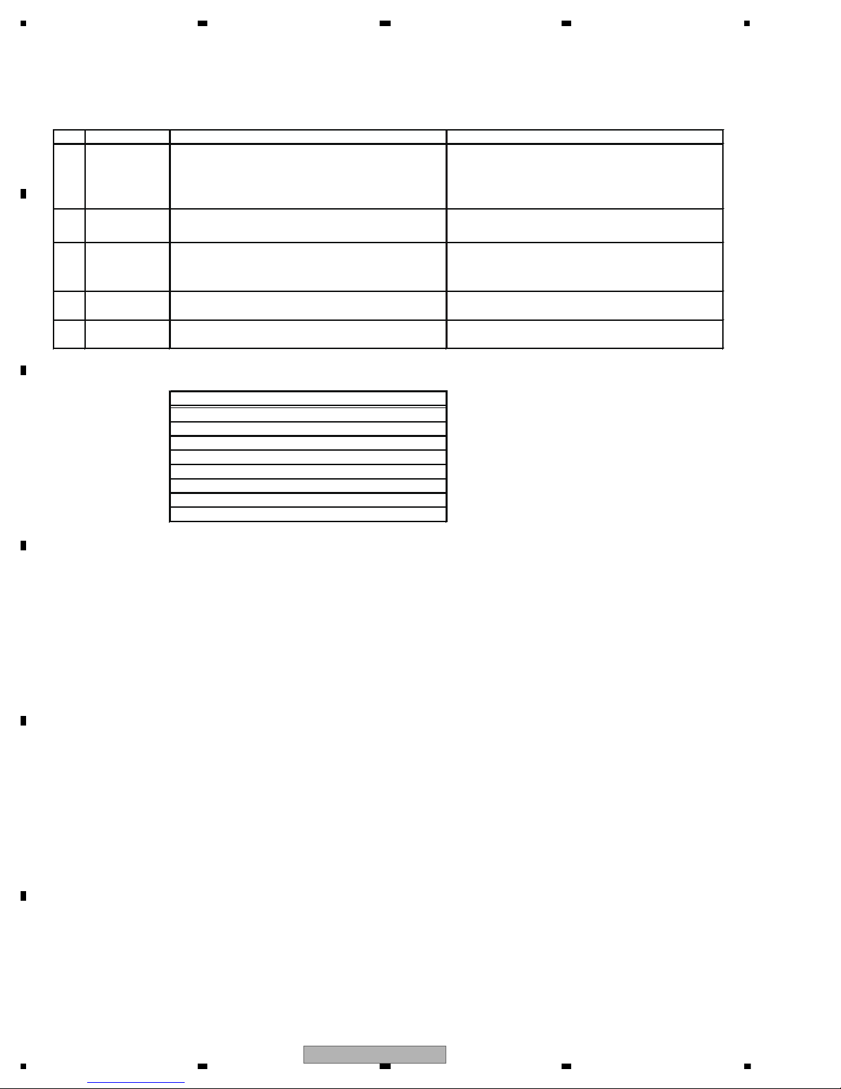
3. BASIC ITEMS FOR SERVICE
To keep the product quality after servicing, please confirm following check points.
No. Procedures Item to be confirmed
1
Confirm whether the customer complain has been
solved.
If the customer complain occurs with the specific
media, use it for the operation check.
The customer complain must not be reappeared.
Display, audio and operations must be normal.
2CD PlaybackaCD.
(Track search)
No malfunction on display, audio and operation.
Display, audio and operations must be normal.
3FM/AM tuner
Check FM/AM tuner action.
(Seek, Preset)
Switch band to check both FMandAM.
Display, audio and operations must be normal.
4 Check whether no disc is inside the product.
The media used for the operating check must be
ejected.
5 Appearance check
No scratches or dirt on its appearance after
receiving it for service.
See the table below for the items to be checked regarding audio:
Item to be checked regarding audio
Distortion
Noise
Volume too low
Volume too high
Volume fluctuating
Sound interrupted
3.1 CHECK POINTS AFTER SERVICING
20
FH-P800BT/XJ/UC
5678
56
7
8
C
D
F
A
B
E
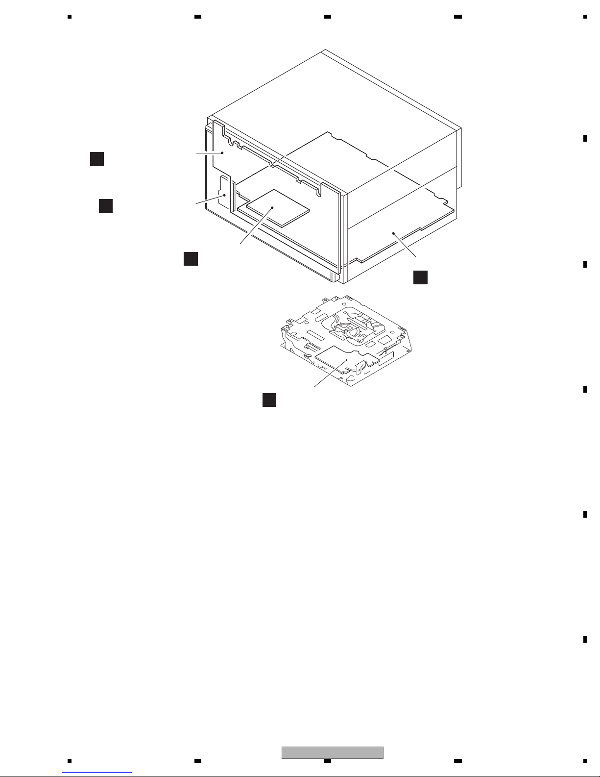
C
CD Core Unit
(S10.5COMP2-iPod-C2)
A
Combi PWB Unit
D
Bluetooth Unit
E
Antenna Unit
B
Keyboard Unit
Unit Number : CZW5569
(FH-P800BT/XJ/UC)
Unit Number : CZW5570
(FH-P8000BT/XJ/UC)
Unit Number : CZW5568
(FH-P80BT/XJ/EW5)
Unit Name : Combi PWB Unit
Unit Number : CZW5571
(FH-P6050UB/XJ/ES)
Unit Name : Comb PWB Unit
Unit Number : CZW5574(UC)
Unit Number : CZW5573(EW5)
Unit Number : CZW5575(ES)
Unit Name : Keyboard Unit
Unit Number : CWN3394(UC,EW5)
Unit Name : Bluetooth Unit
Unit Number : CWX3624
Unit Name : CD Core Unit
(S10.5COMP2-iPod-C2)
3.2 PCB LOCATIONS
FH-P800BT/XJ/UC
21
1234
1234
C
D
F
A
B
E
3.3 JIGS LIST
- Jigs List
Name
Test Disc
L.P.F.
Jig No.
TCD-782
GGF1539
Remarks
Checking the grating
Checking the grating (Two pieces)
Removing the cord assy (BT antenna cable)
- Grease List
Name
Grease
Grease
Grease No.
GEM1024
GEM1045
Remarks
CD Mechanism Module
CD Mechanism Module
Before shipping out the product, be sure to clean the
following portions by using the prescribed cleaning
tools:
Portions to be cleaned Cleaning tools
CD pickup lenses Cleaning liquid : GEM1004
Cleaning paper : GED-008
3.4 CLEANING
22
FH-P800BT/XJ/UC

5678
56
7
8
C
D
F
A
B
E
FH-P800BT/XJ/UC
23
1234
1234
C
D
F
A
B
E
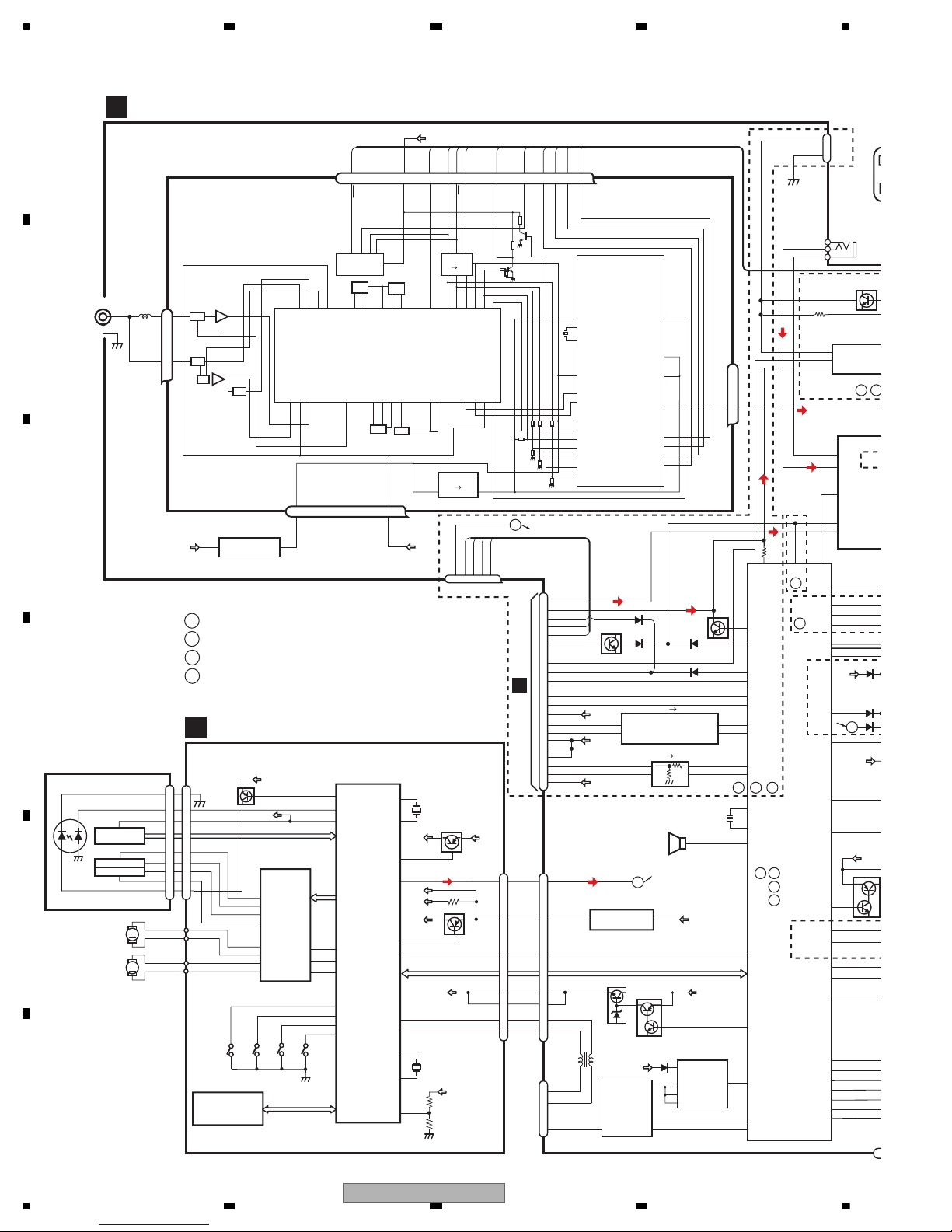
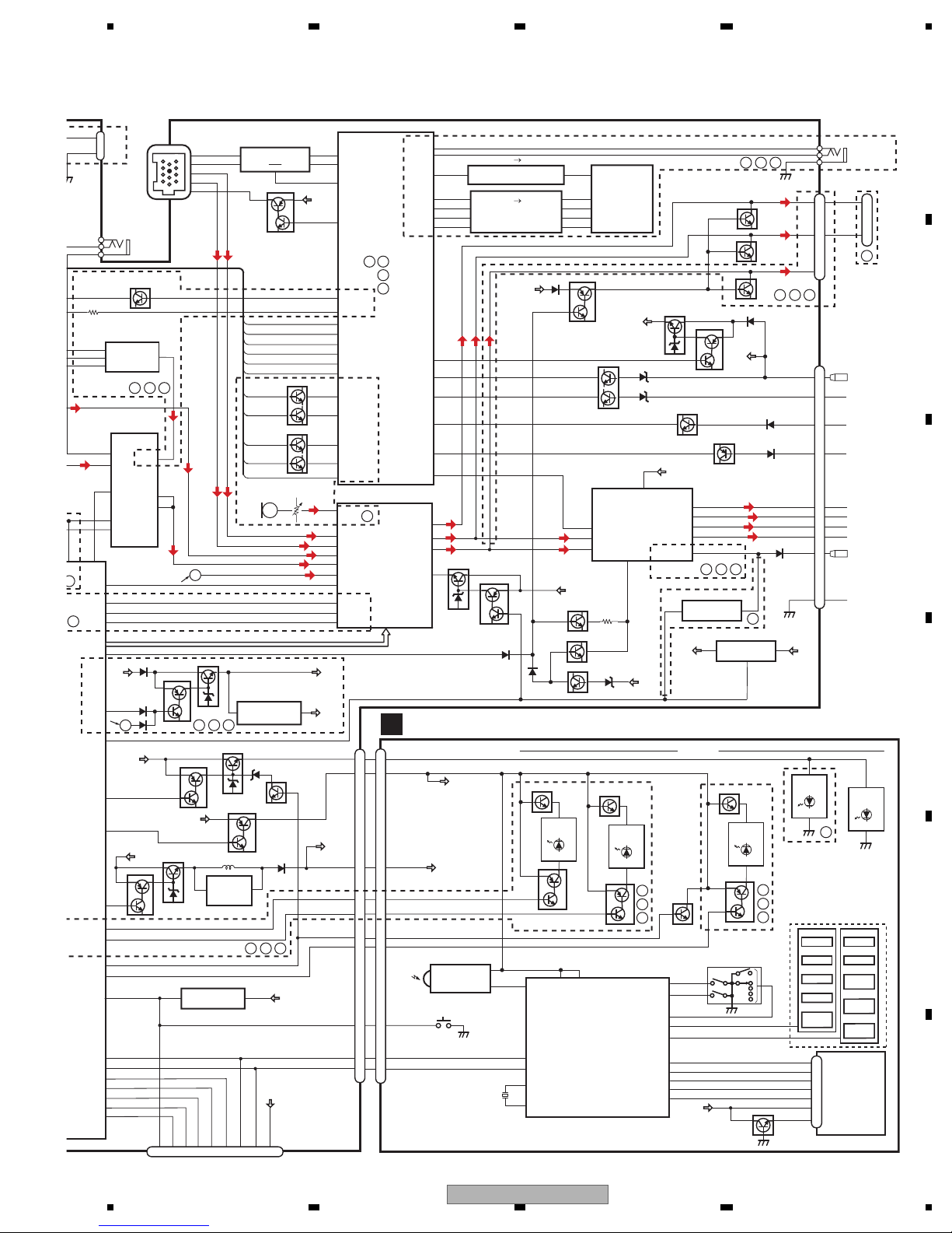
4. BLOCK DIAGRAM
3V 5V
LOUT
MUTE
BTPW
XIN
XOUT
SYSTEM
CONTROLLER
IC1(1/2)
MUTE
JA100
TUN_3.3V
1
2,3
JA150(1/2)
CN200
COMBI PWB UNIT
1
64
85
SYSPW
ILMPW
SWVDD
OELPW
A
AUX
18
19
4
3
2
3
1
7
4
A8V
A8V
VDD5V
ANTENNA
INDTEL
BRST,BRXEN,BSRQ,BDATA,BSCK
VDD5V
EVOLSW2
BTMUTE
BTCTS
BTRX
BTTX
BTRTS
PEE
BTRST
BTTEST
TELBEEP EVOL
SW2
EVOL
SW1
13
X1
20MHz
11
CE2
SL
CK
CE1
LDET
DI
DO
Q350
Q300
1
2
3
61
34
33
68
45
66
65
63
22 45 40
15
17
32
6
5
9
IC50(1/2)
TC74VHCT08AFT
5V 3V
BTRTS
AUDIO8V
BTTX
CDL
BTRX
BTBTS
MICIN
TELOUT
HFAV
BTRST
BTTEST
9
3A 3Y
4Y4A
8
12
11
AUXR
AUXL
MICIN
AUXG
11
26
12
RESET
92
VDCONT
DDSYNC
USBCTL
FLG
CDRST
CN800
34
33
35
54
55
56
DACCK
DACDT
DACCS
DACCS
DACDT
DACCK
24
36
BOOTE
AVL
8
OTX
39
BT3V
11
BT5V
8
16
15
9
SW2
SW1
+IN2C
-IN2C
AUXL
L-IN2B
OUT2
+IN2A
40
ORX ORST
BOOTE
ORST
OTX
ORX
34
6
7
2
BTPW2
CN300
MIC
CN810
SELECTOR
IC350
BA3131FS
MUTE
+IN2B
18
12
A8V
10
D
CN76
BZ1
CD_3.3V
1
3
IC260
NJM2885DL1-33
E
F
C
D
A B C
E
DIM
INDAV
DISPOFF
RESET
B.U
6
2
7
PHONE MIXIN
IC300
NJM4558MD
B_-IN
A_OUT
A_-IN
B_OUT
IC130
NJM2885DL1-33
1
3
VDD
2
1
DPDT
CE
CLCK
BUSY
KYDT
35
32
31
44
39
7
29
30
10
52
57
58
CNVSS
EPM
USB5V
USBDP
USBDP
USBDM
USBDM
18
20
19
87
USB
VD_7.5V
Q250
Q251
B.U
7
1
5
24
1
35
6
USB_5V
IC280
BD9781HFP
IC290
R5523N001B
VIN
EN/SYNC
FLG
EN
VIN
VOUT
FB
SW
INV
B.U
JA290
VD
B.U
Q701
36
38
37
OEL15V
Q301
IP-BUS
ASLIN
93
EMUTE
23
SACLK
59
SAOUT
90
A B
A B
C
D
:
PEG437A
:
PEG436A
:
PEG438A
:FH-P800BT/XJ/UC
:FH-P8000BT/XJ/UC
:FH-P80BT/XJ/EW5
:FH-P6050UB/XJ/ES
A
B
C
D
RESET
CN1
FMRF
ANT adj
RF adj
FM ANT
T51
CF52
RFGND
VDD_3.3
OSCGND
DGND
AUDIOGNDNCVCC
3.3V
2.5V
IC 4
3.3V 2.5V
IC 2
2.5V
NC
CE2
ROM_VDD
SL
DI
CK
CE1
LDET
DO
RDS_CK
RDS_DATA
RDS_LOCK
RDS_HSLK
76 13 5 1098 11 14 18192021
1
3
217 12 15 22 16 4
IC 1
3.3V
AM ANT
FMRF
FM/AM TUNER UNIT
ATT
LPF
OSC
IC 3 EEPROM
5.0V
IC 5
5V 3.3V
ATT
MIXER, IF AMP
DET, FM MPX,
RDS DECODER
23
Lch
PICKUP UNIT
(P10.5)(SERVICE)
CD CORE UNIT(S10.5COMP2-iPod-C2)
C
BRST,BRXEN,BSRQ
CN701
Q101
M
LD
MD
S903
DSCSNS
SPINDLE
MOTOR
M
LOADING/CARRIAGE
MOTOR
LD-
MD
15
5
HOLOGRAM
UNIT
IC301
BA5839FP
IC201
PE5647A
RF AMP, CD DECODER, MP3&WMA DECODER
DIGITAL SERVO/DATA•PROCESSOR
CPU, USB HOST CONTROLLER
ACTUATOR/
MOTOR DRIVER
2
VD
VD
13
LOUT
9
CN101
16
SOP
15
SOM
18
LCOP
17
LCOM
21
CLCONT
55
LOUT
9
CONT
TD,FD
AC,BD,E,F
SD,MD
S901
HOME
S904
12EJ
S905
8EJ
LD+
14
141
LD
142
PD
12EJ
CONT
CLCONT
HOME
8
9
20
41
VDD
1
VDD2
BDATA,BSCK
Q201
17
/ADENA
VDD
15
5
FOCUS ACT.
TRACKING ACT.
FOP
TOP
2
1
TOP
FOP
11
FOP
14
TOP
2
1
14
8EJ
7
DSCSNS
10
VDD3
16
/RESET
8
/RESET
88
VREF
REFO
133
REFOUT
33
FOM
FOM
12
FOM
44
TOM
TOM
13
TOM
22
LOEJ
LOEJ
28
52
50
X201
XTAL
/XTAL
16.93MHz
VDSENS
11
VD
16
17
DP
DM
4
5
DM
DP
2
1
X205
48MHz
USBXTAL
/USBXTAL
VDD2
Q102
39
/PUEN
VCC
VDD2
IC205
341S2159
iPod AUTHENTICATION COPROCESSOR
CPRST
SDA,SCL
24
FH-P800BT/XJ/UC
5678
56
7
8
C
D
F
A
B
E
Q906
Q909
Q910
Q908
Q903
Q905
Q902
Q904
S901
Q901
OEL_+B
ILM_+B
SWVDD
RESET
INDTEL
INDAV
DIM
DISPOFF
9
12
1
13
CN901
RESET
8
3
6
2
KEYBOARD UNIT
B
D901-D904
D907,D908
D912-D919
D911
D911
D910
D909
SWVDD
OEL_+B
OEL DRIVER/
KEY CONTROLLER
IC902
PEG439A
REM
VCC VREF
KYDT
DPDT
ROT1
ROT0
ADKY0
ADKY1
ADKY2
4
KYDT
DPDT
OEL_+B
IC901
GP1UX51RK
REMOTE CONTROL
SENSOR
OPT IN
3
1
10
13
SCL
SIRX
XRES
XCMD
VAH
VKH
12
716
5
XOUT
XIN
4
X901
10MHz
6
ROTARY COMMANDER
9
1
9
18
19
17
DCLK
1
DOUT
2
XREST
11
XCMD
20
15
KEY MATRIX
ILLUMI
OEL UNIT
S904
S906
S902
RDM
BAND
SOURCE
S905
S907
S903
EJECT
LIST
CLOCK
/TA/TI
S910
MUTE
/SW
S912
PHONE
/EQ
S909
DISP
S911
S.Rtrv
COMP
20
21
18
19
XI
MCLK
14
10
7
6
C
D
B
A
C
B
A
BSENS
ISENS
B.U
21
TELIN
8
73
ASENS
72
DALMON
MEMDI
MEMCS
MEMWP
MEMDO
MEMCK
67
38
PRE/SW_L
39
43
Rear_L
VP
MUTE
BTPW
9
6,20
7
17
19
OUT1+
VCC1,VCC2
OUT1-
OUT3+
OUT3-
ACC
ILL
IN3_L
8
6
7
22
IN1_L
IN4-_L
IN4+_L
MIC_in
IN2_L
9
28
27
79
80
81
IN1
STBY
11
4
IN3
OEL15V
15
22
IC400
PML017A
VR430
MIC430
POWER AMP
IC550
PA2029A
VDD5V
Q650
Q610
SYSPW
JA150(1/2)
ASENBO
TX
RX
IPPW
BUS-
BUS+S1ROUT
STB
BTMUTE2
TELBEEP2
ELECTRONIC VOLUME/
SOURCE SELECTOR
MIC
MUTE
VST,VCK,VDT
TUNL
BUSL-
BUSL+
CDL
A8V
B.U
BT3V
BT5V
1
64
85
SYSPW
ILMPW
SWVDD
OELPW
Q850
Q101
Q100
MUTE
VP_12V
Q470
Q460
Q450
40
Front-L
AMPPW
49
25
SW_OUT
VDD_5V
BSENS
ASENS
AUDIO_8V
4
TEL_MUTE
10
12
3
5
7
9
16
6
15
JA600
AUX
SL
TUNPCE1
TUNPDO
TUNPDI
95
69
24
70
47
46
TUNPCK
48
CE1
DO
DI
CK
Q651
KEYD
2
KEYAD
89
Q852
RL
FL
SWL
RL
FL
SWLFLSWL
INDTEL
JA450
RCA
OUT
RL-
RL+
FL-
FL+
GND
B.REM
TUNPCE2
CE2
EVOL
SW1
B.U
1
1
3
2
6
1
IC660
NJM2388F84
B.REM CONT
IC510
TPD1018F
IC670
NJM2885DL1-33
4
SL
RCK
16
RDS_CK
RDSLK
82
RDS_LOCK
RDS57K
83
RDS_DATA
RDT
84
RDS_HSLK
LDET
17
LDET
BT_3V
10
5
1
2
1
3
45 40
BU
KEYD
KEYAD
AUXR
AUXL
AUXG
Q490
B.U
Q851
TEL MUTE
Q630
ISENS
Q620
Q440
Q441
14
17
8
16
15
9
SW2
SW1
+IN2C
-IN2C
L-IN2B
OUT2
+IN2A
CN300
MIC
SELECTOR
IC350
BA3131FS
MUTE
+IN2B
18
SYSTEM
CONTROLLER
IC1(2/2)
ACC
GND
TEL_MUTE
ILL
BU
RL-
RL+
FL-
FL+
B.REM
SOUTL
F
C
C
D
E
8
5
DIM
INDAV
DISPOFF
RESET
BT_5V
B.U
Q671
Q670
WIRED
REMOTE
1
20
6
2
7
PHONE MIXING
IC300
NJM4558MD
B_-IN
A_OUT
A_-IN
B_OUT
2
1
JA150(2/2)
DPDT
CE
CLCK
BUSY
KYDT
DPDT
KYDT
RESET
35
32
31
44
39
7
29
30
10
DIM
DISPOFF
52
INDAV
INDTEL
57
58
CNVSS
EPM
4
15
14
16
9
12
13
11
82356 9 4101
MEMORY
3V 5V
5V 3V
4
43
3
5
42
1
3
12
9
4
3
11
8
6
8
5
1
2
4
1
CS#
SO
1Y
2A
1A
4A
3A 3Y
4Y
1Y
2Y
1A
WP#
SI
SCK
IC50(2/2)
TC74VHCT08AFT
IC60
TC74VHC08FT
IC70
LE25FW
203PATT
VDD5V
RESET
2
1
IC35
PST3435UL
SWVDD
B.U
Q701
7,8
IC700
NJM2360M
1
OEL_15V
Q700
OEL15V
36
38
Q90
VDD5V
SW_5V
ILM_12.2V
ILM_+B
37
OEL15V
Q681
Q680
Q682
Q750
Q301
B.U
IP-BUS
7
11
8
BUSL-
BUSL+
5
1
JA750
1
2
5
6
8
IP-BUS DRIVER
IC750
HA12241FP
ASLIN
20
93
Noise_
DET_out
EMUTE
14
23
MUTE
SACLK
13
59
SA_CLK
SAOUT
12
90
SA_OUT
A B
C
D
:
PEG437A
:
PEG436A
:
PEG438A
A B C
A B C
A B C
BAC D
A B C
A B C
B.U
RESET
BUSY
CLK
CE
EPM
CNVss
TXD
RXD
VCC
VDD5V
CN80
CN1
OEL_+B
D
FH-P800BT/XJ/UC
25
1234
1234
C
D
F
A
B
E
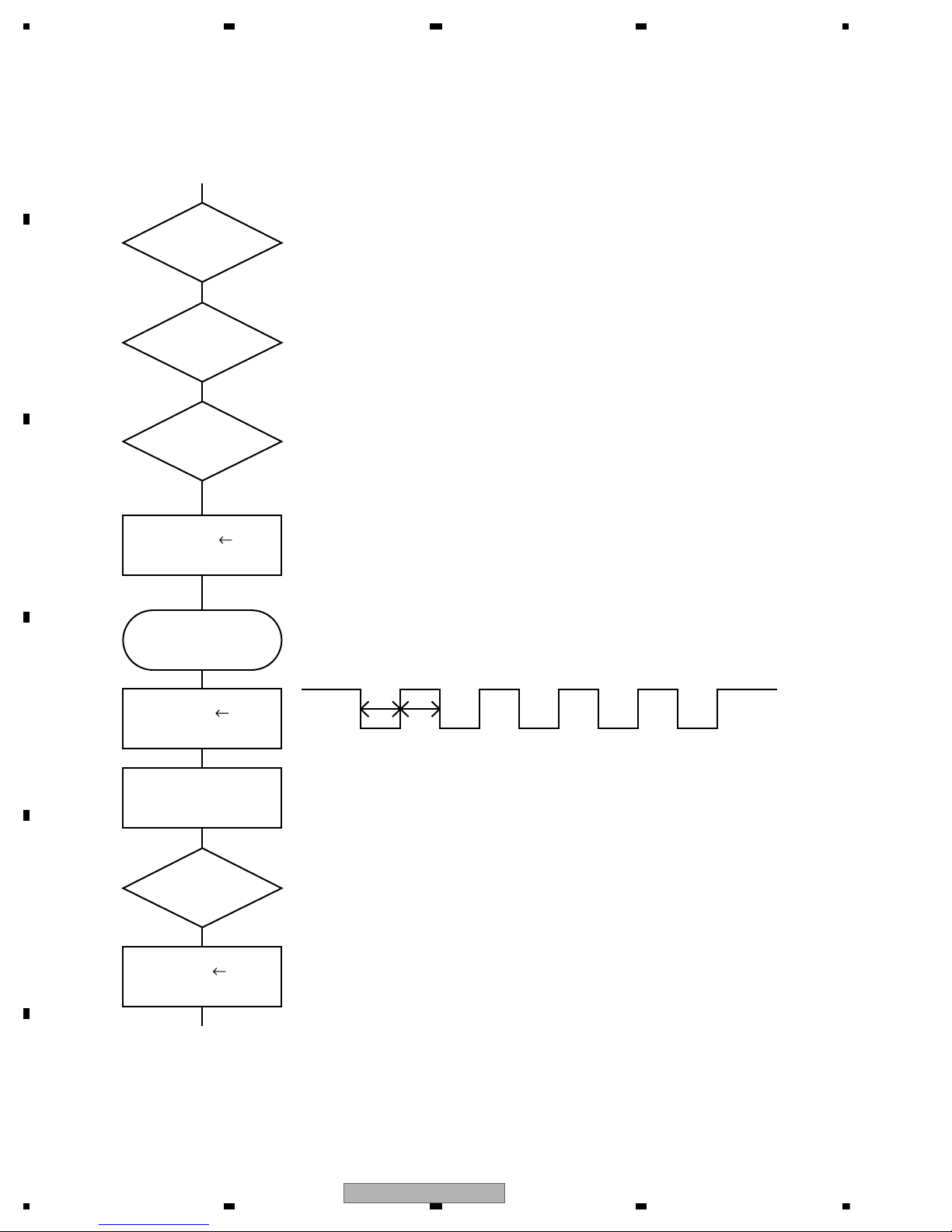
5. DIAGNOSIS
SWVDD
Vcc1 = 5 V
Pin 14
Power ON
bsens = L
bsens
Pin 73
asens
Pin 72
asens = L
H
Pin 38
Source keys
operative
Completes power-on operation.(After that, proceed to each source operation.)
SYSPW H
Pin 1
ASENBO H
Pin 80
Starts communication with Grille microcomputer.
Source ON
500 ms
500 ms
In case of the above signal, the communication
with Grille microcomputer may fail.
If the time interval is not 500 msec, the oscillator
may be defective.
5.1 OPERATIONAL FLOWCHART
26
FH-P800BT/XJ/UC
5678
56
7
8
C
D
F
A
B
E
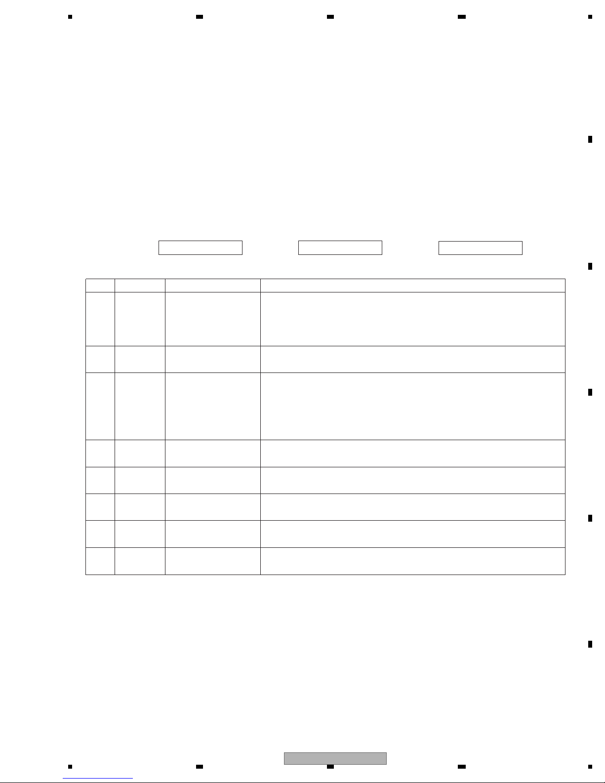
- Error Messages
If a CD is not operative or stopped during operation due to an error, the error mode is turned on and cause(s) of
the error is indicated with a corresponding number. This arrangement is intended at reducing nonsense calls from
the users and also for facilitating trouble analysis and repair work in servicing.
(1) Basic Indication Method
1) When SERRORM is selected for the CSMOD (CD mode area for the system), error codes are written to DMIN
(minutes display area) and DSEC (seconds display area). The same data is written to DMIN and DSEC. DTNO
remains in blank as before.
2) Head unit display examples
Depending on display capability of LCD used, display will vary as shown below. xx contains the error number.
8-digit display 6-digit display 4-digit display
ERROR-xx ERR-xx E-xx
(2) Error Code List
Code Class Displayed error code Description of the code and potential cause(s)
10 Electricity Carriage Home NG CRG can't be moved to inner diameter.
SERVO LSI Com- CRG can't be moved from inner diameter.
munication Error -> Failure on home switch or CRG move mechanism.
Communication error between microcomputer and SERVO LSI.
11 Electricity Focus Servo NG Focusing not available.
-> Stains on rear side of disc or excessive vibrations on REWRITABLE.
12 Electricity Spindle Lock NG Spindle not locked. Sub-code is strange (not readable).
Subcode NG -> Failure on spindle, stains or damages on disc, or excessive vibrations.
A disc not containing CD-R data is found.
Turned over disc are found, though rarely.
CD signal error.
17 Electricity Setup NG AGC protection doesn't work. Focus can be easily lost.
-> Damages or stains on disc, or excessive vibrations on REWRITABLE.
30 Electricity Search Time Out Failed to reach target address.
-> CRG tracking error or damages on disc.
44 Electricity ALL Skip Skip setting for all track.
(CD-R/RW)
50
Mechanism
CD On Mech Error Mechanical error during CD ON.
-> Defective loading motor, mechanical lock and mechanical sensor.
A0 System Power Supply NG Power (VD) is ground faulted.
-> Failure on SW transistor or power supply (failure on connector).
Remarks: Mechanical errors are not displayed (because a CD is turned off in these errors).
Unreadable TOC does not constitute an error. An intended operation continues in this case.
Upper digits of an error code are subdivided as shown below:
1x: Setup relevant errors, 3x: Search relevant errors, Ax: Other errors.
5.2 ERROR CODE LIST
FH-P800BT/XJ/UC
27
1234
1234
C
D
F
A
B
E
28
FH-P800BT/XJ/UC
5678
56
7
8
C
D
F
A
B
E
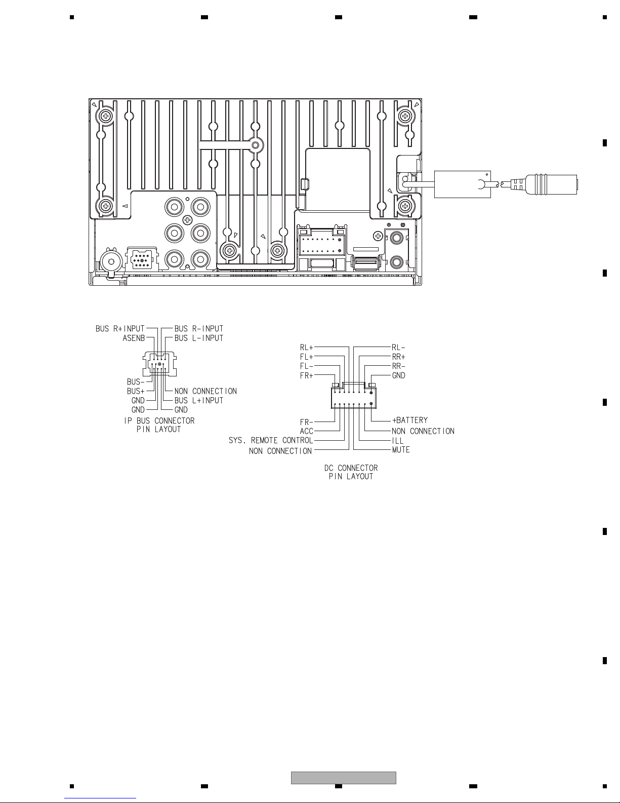
FRONT
REAR
RL
SW
FUSE 10A
M4X8 MAX
ANTENNA JACK
FRONT OUTPUT(UC,EW5)
REAR OUTPUT
SUBWOOFER OUTPUT
USB
AUX JACK
WIRED REMOTE INPUT(UC,EW5)
MIC INPUT(UC,EW5)
5.3 CONNECTOR FUNCTION DESCRIPTION
FH-P800BT/XJ/UC
29

1234
1234
C
D
F
A
B
E
6. SERVICE MODE
1) Cautions on adjustments
In this product the single voltage (3.3 V) is used for the
regulator. The reference voltage is the REFO1 (1.65 V)
instead of the GND.
If you should mistakenly short the REFO1 with the GND
during adjustment, accurate voltage will not be obtained,
and the servo’s misoperation will apply excessive shock
to the pickup. To avoid such problems:
a. Do not mix up the REFO1 with the GND when
connecting the (-) probe of measuring instruments.
Especially on an oscilloscope, avoid connecting the (-)
probe for CH1 to the GND.
b. In many cases, measuring instruments have the same
potential as that for the (-) probe. Be sure to set the
measuring instruments to the floating state.
c. If you have mistakenly connected the REFO1 to the GND,
turn off the regulator or the power immediately.
Before mounting and removing filters or leads for
adjustment, be sure to turn off the regulator.
For stable circuit operation, keep the mechanism
operating for about one minute or more after the
regulator is turned on.
In the test mode, any software protections will not
work. Avoid applying any mechanical or electrical
shock to the mechanism during adjustment.
The RFI and RFO signals with a wide frequency range
are easy to oscillate. When observing the signals,
insert a resistor of 1k ohms in series.
The load and eject operation is not guarantied with the
mechanism upside down. If the mechanism is blocked
due to mistaken eject operation, reset the product or
turn off and on the ACC to restore it.
2) Test mode
This mode is used to adjust the CD mechanism module.
To enter the test mode.
While pressing the SOURCE and CLOCK(TA) keys at the
same time, reset.
To exit from the test mode.
Turn off the ACC and back up.
Notes:
a. During ejection, do not press any other keys than the
EJECT key until the loaded disc is ejected.
b. If you have pressed the (->) key or (<-) key during focus
search, turn off the power immediately to protect the
actuator from damage caused by the lens stuck.
c. For the TR jump modes except 100TR, the track jump
operation will continue even if the key is released.
d. For the CRG move and 100TR jump modes, the tracking
loop will be closed at the same time when the key is
released.
e. When the power is turned off and on, the jump mode
is reset to the single TR (91), the RF amp gain is set to 0 dB,
and the auto-adjustment values are reset to the default
settings.
6.1 CD TEST MODE
30
FH-P800BT/XJ/UC
 Loading...