

Pioneer FHP-4200-MP Service manual
ORDER NO.
CRT3417
FH-P4200MP/XU/UC
MULTI-CD CONTROL DSP HIGH POWER CD/MP3/WMA/
CASSETTE PLAYER WITH FM/AM TUNER
FH-P4200MP
FH-P4200MP
FH-P4200MP
This service manual should be used together with the following manual(s):
Model No. Order No. Mech.Module Remarks
CX-3158 CRT3394 S10.1AAC CD Mech. Module:Circuit Description, Mech. Description, Disassembly
CX-1011 CRT2406 3L Cassette Mech. Module:Mech. Description, Disassembly, Adjustment
Dolby noise reduction manufactured under license from Dolby Laboratories Licensing
Corporation.
"Dolby" and the double-D symbol are trademarks of Dolby Laboratories Licensing Corporation.
/XU/ES
/XU/CN
/XU/UC
For details, refer to "Important Check Points for Good Servicing".
PIONEER CORPORATION 4-1, Meguro 1-chome, Meguro-ku, Tokyo 153-8654, Japan
PIONEER ELECTRONICS (USA) INC. P.O. Box 1760, Long Beach, CA 90801-1760, U.S.A.
PIONEER EUROPE NV Haven 1087, Keetberglaan 1, 9120 Melsele, Belgium
PIONEER ELECTRONICS ASIACENTRE PTE. LTD. 253 Alexandra Road, #04-01, Singapore 159936
PIONEER CORPORATION 2005
K-ZZD.FEB. 2005 Printed in Japan
1234
SAFETY INFORMATION
CAUTION
A
This service manual is intended for qualified service technicians; it is not meant for the casual do-it-yourselfer.
Qualified technicians have the necessary test equipment and tools, and have been trained to properly and safely
complex products such as those covered by this manual.
repair
Improperly performed repairs can adversely affect the safety and reliability of the product and may void the
warranty.
trying to do so
ARNING
W
This product contains lead in solder and certain electrical parts contain chemicals which are known to the
state
Health & Safety Code Section 25249.6 - Proposition 65
B
If you are not qualified to perform the repair of this product properly and safely, you should not risk
and refer the repair to a qualified service technician.
of California to cause cancer, birth defects or other reproductive harm.
CAUTION
Danger of explosion if battery is incorrectly replaced.
Replaced only with the same or equivalent type recommended by the manufacture.
Discord used batteries according to the manufacture’s instructions.
C
- Service Precaution
1. You should conform to the regulations governing the
product (safety, radio and noise, and other regulations),
and should keep the safety during servicing by following
the safety instructions described in this manual.
2. Before disassembling the unit, be sure to turn off
the power. Unplugging and plugging the connectors
during power-on mode may damage the ICs inside
the unit.
D
E
3. To protect the pickup unit from electrostatic discharge
during servicing, take an appropriate treatment
(shorting-solder) by referring to "the DISASSEMBLY" .
4. After replacing the pickup unit, be sure to check the
grating.
F
2
1234
FH-P4200MP/XU/UC
5678
[Important Check Points for Good Servicing]
In this manual, procedures that must be performed during repairs are marked with the below symbol.
Please be sure to confirm and follow these procedures.
1. Product safety
Please conform to product regulations (such as safety and radiation regulations), and maintain a safe servicing environment by
following the safety instructions described in this manual.
1 Use specified parts for repair.
Use genuine parts. Be sure to use important parts for safety.
2 Do not perform modifications without proper instructions.
Please follow the specified safety methods when modification(addition/change of parts) is required due to interferences such as
radio/TV interference and foreign noise.
3 Make sure the soldering of repaired locations is properly performed.
When you solder while repairing, please be sure that there are no cold solder and other debris.
Soldering should be finished with the proper quantity. (Refer to the example)
4 Make sure the screws are tightly fastened.
Please be sure that all screws are fastened, and that there are no loose screws.
5 Make sure each connectors are correctly inserted.
Please be sure that all connectors are inserted, and that there are no imperfect insertion.
6 Make sure the wiring cables are set to their original state.
Please replace the wiring and cables to the original state after repairs.
In addition, be sure that there are no pinched wires, etc.
7 Make sure screws and soldering scraps do not remain inside the product.
Please check that neither solder debris nor screws remain inside the product.
8 There should be no semi-broken wires, scratches, melting, etc. on the coating of the power cord.
Damaged power cords may lead to fire accidents, so please be sure that there are no damages.
If you find a damaged power cord, please exchange it with a suitable one.
9 There should be no spark traces or similar marks on the power plug.
When spark traces or similar marks are found on the power supply plug, please check the connection and advise on secure
connections and suitable usage. Please exchange the power cord if necessary.
0 Safe environment should be secured during servicing.
When you perform repairs, please pay attention to static electricity, furniture, household articles, etc. in order to prevent injuries.
Please pay attention to your surroundings and repair safely.
A
B
C
D
2. Adjustments
To keep the original performance of the products, optimum adjustments and confirmation of characteristics within specification.
Adjustments should be performed in accordance with the procedures/instructions described in this manual.
3. Lubricants, Glues, and Replacement parts
Use grease and adhesives that are equal to the specified substance.
Make sure the proper amount is applied.
4. Cleaning
For parts that require cleaning, such as optical pickups, tape deck heads, lenses and mirrors used in projection monitors, proper
cleaning should be performed to restore their performances.
5. Shipping mode and Shipping screws
To protect products from damages or failures during transit, the shipping mode should be set or the shipping screws should be
installed before shipment. Please be sure to follow this method especially if it is specified in this manual.
56
FH-P4200MP/XU/UC
E
F
7
8
3

1234
CONTENTS
SAFETY INFORMATION.....................................................................................................................................2
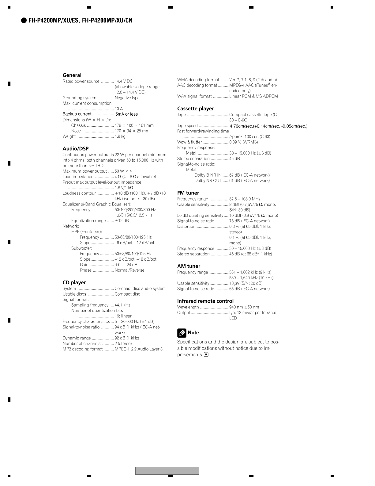
1. SPECIFICATIONS ............................................................................................................................................ 5
2. EXPLODED VIEWS AND PARTS LIST............................................................................................................ 8
A
B
C
2.1 PACKING ................................................................................................................................................... 8
2.2 EXTERIOR............................................................................................................................................... 10
2.3 CD MECHANISM MODULE.....................................................................................................................12
2.4 CASSETTE MECHANISM MODULE....................................................................................................... 14
3. BLOCK DIAGRAM AND SCHEMATIC DIAGRAM..........................................................................................16
3.1 BLOCK DIAGRAM...................................................................................................................................16
3.2 OVERALL CONNECTION DIAGRAM(GUIDE PAGE).............................................................................. 18
3.3 KEYBOARD UNIT.................................................................................................................................... 24
3.4 CD MECHANISM MODULE.....................................................................................................................26
3.5 CASSETTE MECHANISM MODULE....................................................................................................... 36
4. PCB CONNECTION DIAGRAM ..................................................................................................................... 38
4.1 TUNER AMP UNIT...................................................................................................................................38
4.2 KEYBOARD UNIT.................................................................................................................................... 42
4.3 CD CORE UNIT.......................................................................................................................................44
4.4 CASSETTE MECHANISM MODULE....................................................................................................... 46
5. ELECTRICAL PARTS LIST ............................................................................................................................ 48
6. ADJUSTMENT ...............................................................................................................................................58
6.1 CD ADJUSTMENT................................................................................................................................... 58
6.2 CHECKING THE GRATING AFTER CHANGING THE PICKUP UNIT.................................................... 60
6.3 ERROR MODE ........................................................................................................................................ 62
6.4 DOLBY B NR ADJUSTMENT..................................................................................................................63
6.5 SYSTEM MICROCOMPUTER TEST PROGRAM................................................................................... 64
7. GENERAL INFORMATION............................................................................................................................. 65
7.1 DIAGNOSIS.............................................................................................................................................65
7.1.1 DISASSEMBLY ..................................................................................................................................... 65
7.1.2 CONNECTOR FUNCTION DESCRIPTION.......................................................................................... 69
7.2 PARTS...................................................................................................................................................... 70
7.2.1 IC .......................................................................................................................................................... 70
7.2.2 DISPLAY............................................................................................................................................... 79
7.3 OPERATIONAL FLOW CHART ............................................................................................................... 81
7.4 CLEANING............................................................................................................................................... 82
8. OPERATIONS ................................................................................................................................................83
D
E
F
4
1234
FH-P4200MP/XU/UC
5678
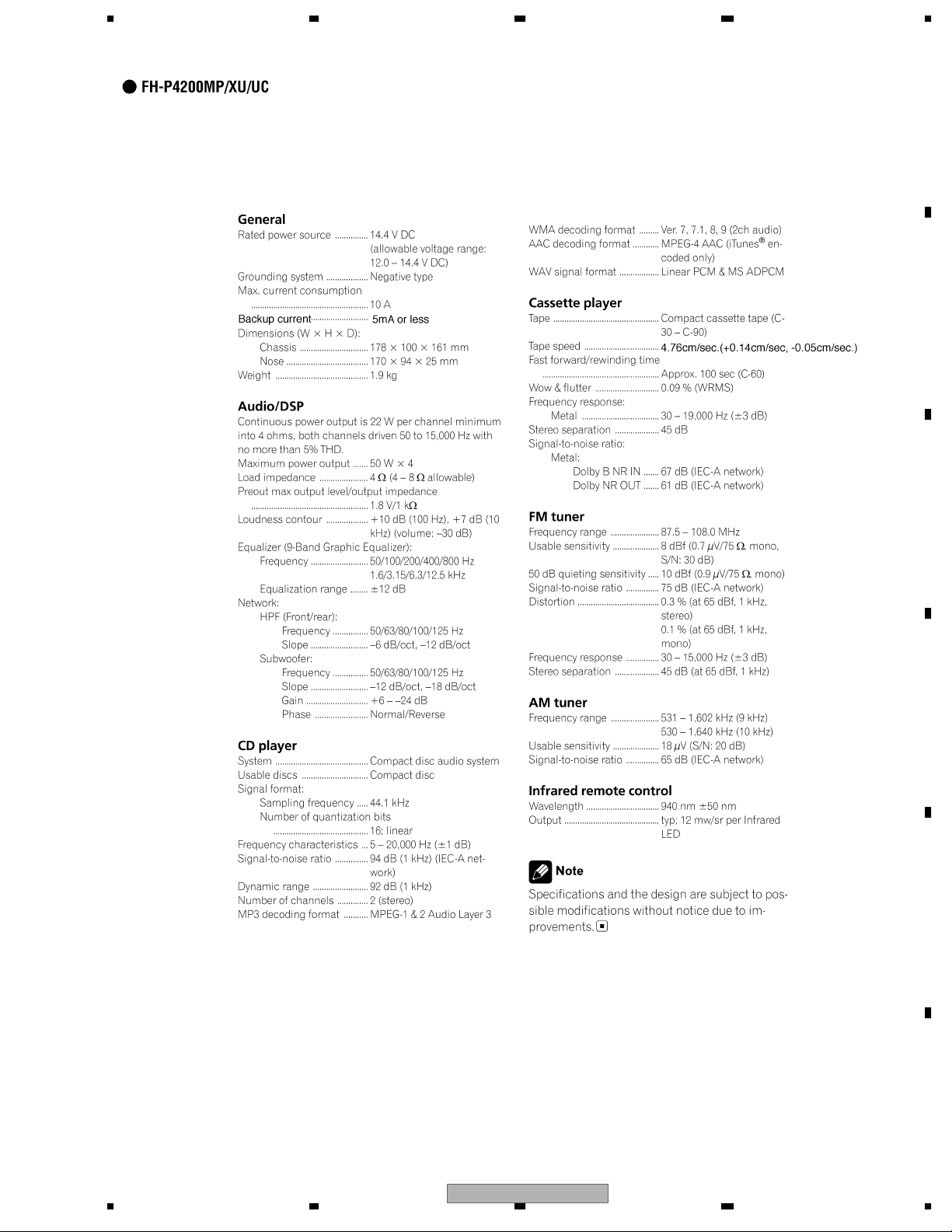
1. SPECIFICATIONS
A
B
C
D
E
56
FH-P4200MP/XU/UC
F
7
8
5
1234
A
B
C
D
E
F
6
1234
FH-P4200MP/XU/UC

5678
A
B
C
D
E
56
FH-P4200MP/XU/UC
F
7
8
7
N
1234
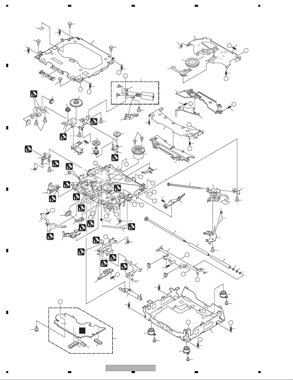
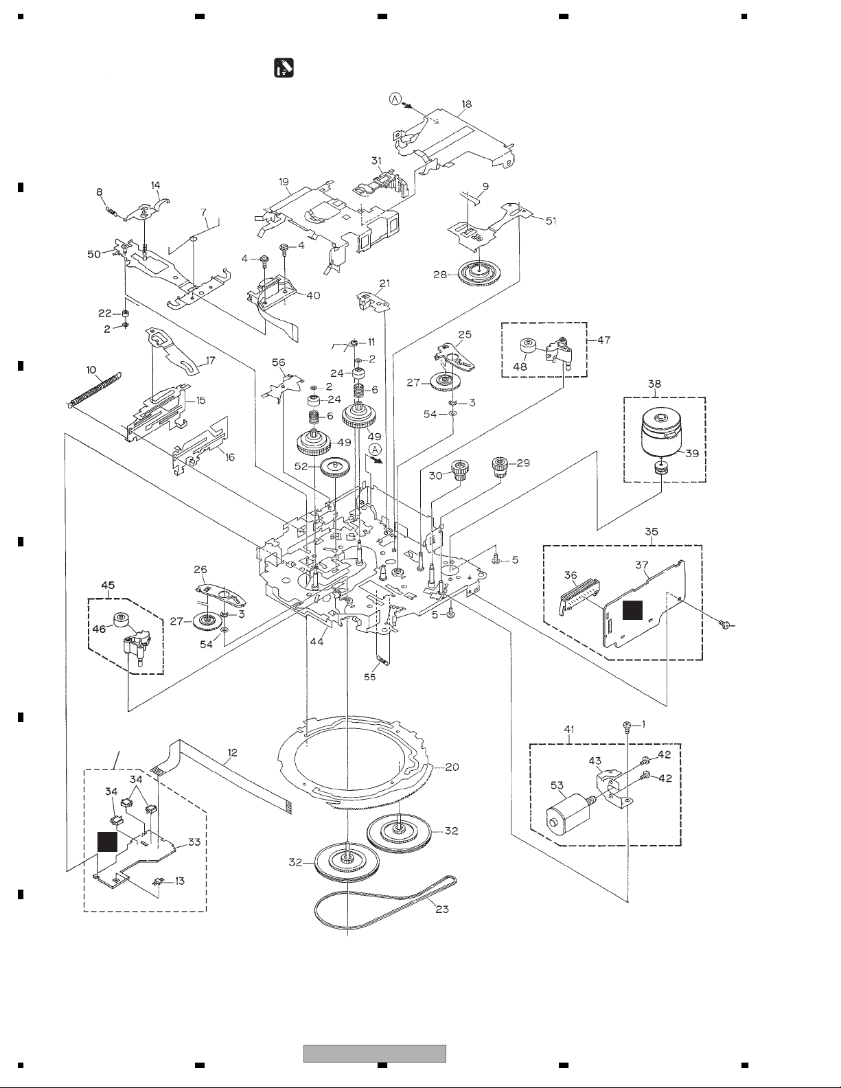
2. EXPLODED VIEWS AND PARTS LIST
OTES : • Parts marked by " * " are generally unavailable because they are not in our Master Spare Parts List.
• The > mark found on some component parts indicatesthe importance of the safety factor of the part.
A
Therefore, when replacing, be sure to use parts of identical designation.
• Screw adjacent to mark on the product are used for disassembly.
• For the applying amount of lobricants or glue, follow the instructions in this manual.
(In the case of no amount instructions,apply as you think it appropriate.)
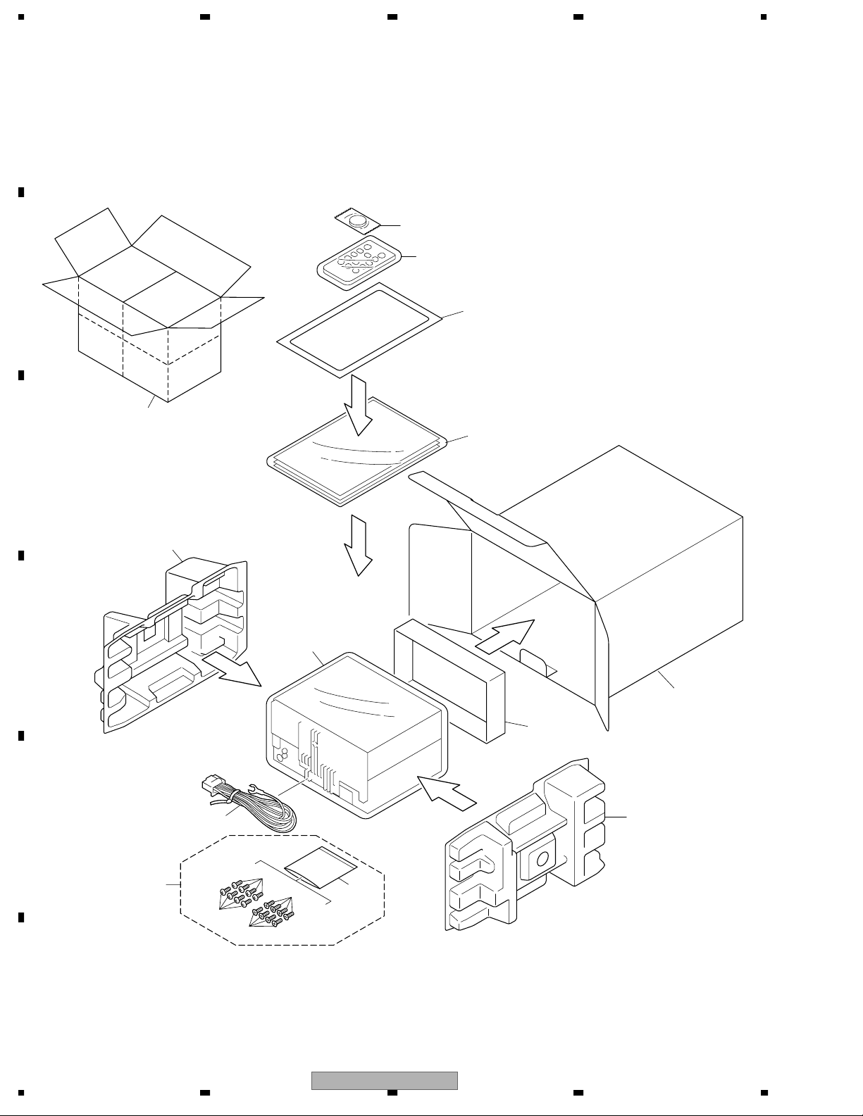
2.1 PACKING
B
"
13
14
15
1
12
C
3
D
E
7
6
2
5
4
10
9
10
11
FH-P4200MP/XU/UC
8
9
F
8
1234
5678
(1) PACKING SECTION PARTS LIST
Mark No. Description Part No.
1 Contain Box See Contrast table(2)
2 Carton See Contrast table(2)
3 Protector YHP5004
4 Protector YHP5003
5 Protector CHP2784
Mark No. Description Part No.
* 11 Polyethylene Bag CEG1158
12-1 Owner’s Manual See Contrast table(2)
12-2 Installation Manual See Contrast table(2)
12-3 Caution Card CRP1310
* 12-4 Card See Contrast table(2)
A
6 Cover See Contrast table(2)
7 Cord Assy See Contrast table(2)
8 Accessory Assy CEA4321
9 Screw BMZ50P080FTC
10 Screw CMZ50P080FTC
* 12-5 Warranty Card See Contrast table(2)
12-6 Polyethylene Bag CEG1116
* 13 Battery CEX1065
14 Remote Control Unit CXC3174
15 Panel See Contrast table(2)
(2) CONTRAST TABLE
FH-P4200MP/XU/UC, FH-P4200MP/XU/ES and FH-P4200MP/XU/CN are constructed the same except for the following:
Mark No. Description FH-P4200MP/XU/UC FH-P4200MP/XU/ES FH-P4200MP/XU/CN
1 Contain Box YHD5006 YHD5005 YHD5007
2 Carton YHA5006 YHA5005 YHA5007
12-1 Owner’s Manual YRD5032 YRD5031 YRB5015
12-2 Installation Manual YRD5034 YRD5033 YRB5016
* 12-4 Card ARY1048 Not used Not used
* 12-5 Warranty Card Not used Not used ARY7046
6 Cover CEG1177 CEG1074 CEG1074
7 Cord Assy XDE7007 CDE7155 CDE7155
15 Panel CNS6675 Not used Not used
Owner's Manual,Installation Manual
Part No. Language
B
C
YRD5031 English, Spanish, Korean
YRD5032 English, French
YRD5033 English, Spanish, Korean
YRD5034 English, French
YRB5015 Casual Chinese
YRB5016 Casual Chinese
D
E
F
56
FH-P4200MP/XU/UC
7
8
9
1234
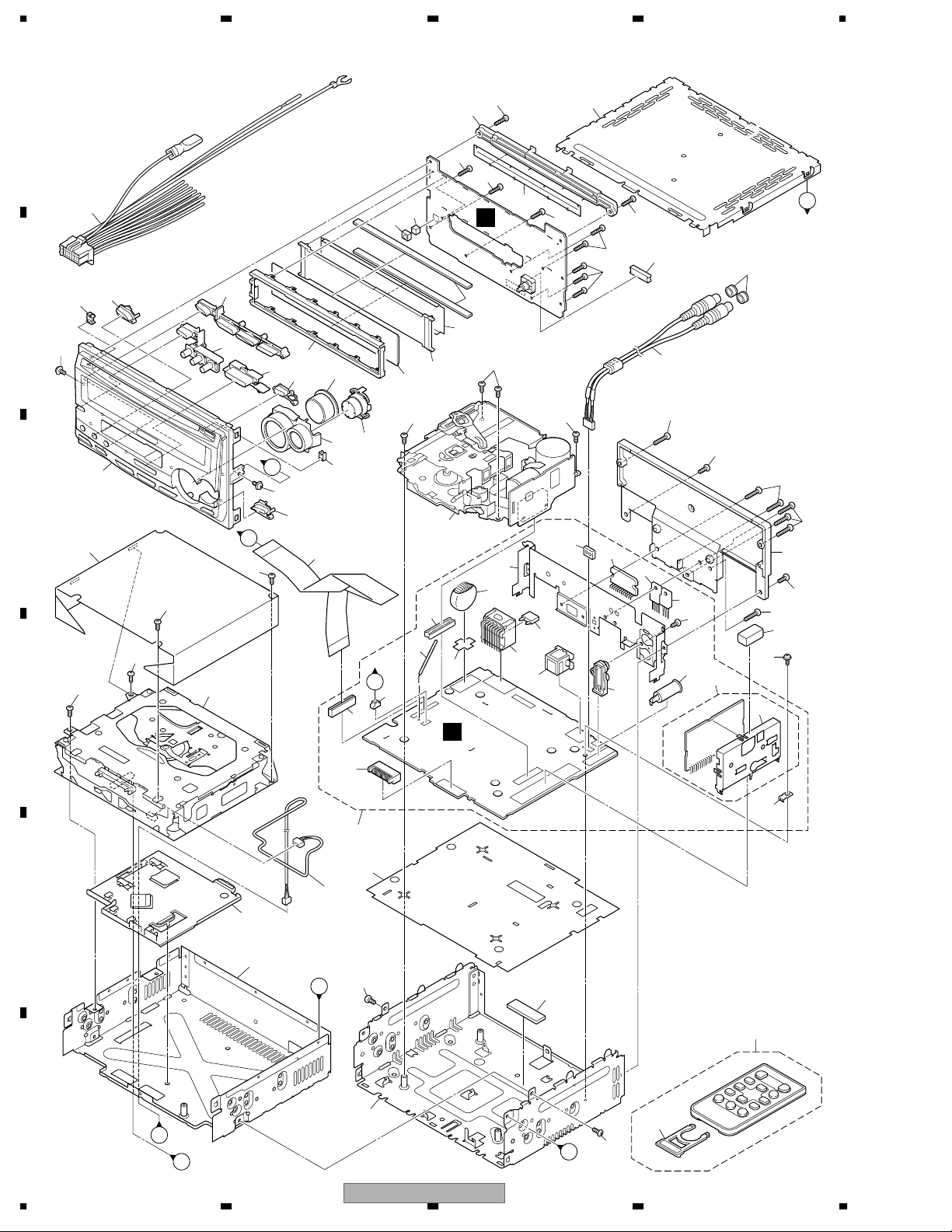
2.2 EXTERIOR
44
A
46
17
44
44
D
15
50
B
55
47
19
63
58
B
45
44
44
44
44
56
6
57
12
52
A
49
48
62
64
53
54
66
61
59
2
2
2
14
51
B
23
2
13
42
37
67
5
36
28
39
C
33
29
31
34
30
68
16
4
3
1
4
18
69
38
27
8
3
4
20
22
40
32
14
65
C
60
2
2
2
D
A
35
41
26
25
24
E
7
9
2
D
21
10
F
C
B
10
1234
43
FH-P4200MP/XU/UC
11
2
A
5678
(1) EXTERIOR SECTION PARTS LIST
Mark No. Description Part No.
1 Screw BMZ26P150FZK
2 Screw BSZ26P060FTC
3 Screw BSZ26P080FZK
4 Screw BSZ26P160FTC
5 Choke Coil(L803) CTH1221
6 Cap See Contrast table(2)
7 Guide CNV8035
8 FM/AM Tuner Unit CWE1646
9 Chassis Unit CXB6784
10 Remote Control Unit CXC3174
11 Cover CNS7068
12
13 Cassette Mechanism Module EXK4060
14 Screw ISS26P060FZK
15 Cord Assy See Contrast table(2)
16 Cord Assy See Contrast table(2)
17 Case YNB5001
18 Heat Sink YNR5001
19 IC(IC1303) TSOP4840SB1
20 Cushion CNM7386
21 Sheet CNM8455
22 Screw ISS26P055FTC
23 Cable YDE5002
24 Cord Assy YDE5003
25 Insulator YNM5008
26 Tuner Amp Unit See Contrast table(2)
27 Screw BPZ26P080FTC
28 Clamper CEF1042
> 29 Fuse(10A) CEK1208
30 Pin Jack(CN350) CKB1056
31 Plug(CN800) CKM1376
* 32 Connector(CN101) CKS2253
33 Connector(CN100) CKS3124
34 Connector(CN170) CKS3408
35 Plug(CN900) CKS3537
CD Mechanism Module(S10.1 AAC)
See Contrast table(2)
Mark No. Description Part No.
36 Connector(CN700) CKS3568
37 Connector(CN351) See Contrast table(2)
38 Antenna Jack(CN401) CKX1056
39 Insulator CNM8843
40 Holder CND1054
41 Terminal(CN400) VNF1084
42 Holder See Contrast table(2)
43 Chassis Unit YXA5095
44 Screw BPZ20P080FTC
45 Cover CNM7086
46 Guide CNV7955
47 Button(ENT,1-6) YAC5042
48 Button(CD EJECT) YAC5043
49 Button(DSP) YAC5046
50 Button(DISP) YAC5047
51 Button(BAND) YAC5048
52 Button(TAPE EJECT) YAC5054
53 Plate YNS5076
54 Lighting Conductor YNV5011
55 Lighting Conductor YNV5012
56 Connector(CN1301) CKS5192
57 Sheet CNM8179
58 Connector CNV7602
59 Lighting Conductor CNV7954
60 Sheet See Contrast table(2)
61 LCD(LCD1301) YAW5049
62 Holder YNC5010
63 Spacer YNM5007
64 Sub Knob Unit YXC5005
65 Sub Grille Unit See Contrast table(2)
66 Sub Button Assy YXC5020
67 IC(IC300) PAL007B
68 IC(IC802) NJM2388F84
69 Transistor(Q814) 2SD2396
A
B
C
D
(2) CONTRAST TABLE
FH-P4200MP/XU/UC, FH-P4200MP/XU/ES and FH-P4200MP/XU/CN are constructed the same except for the following:
Mark No. Description FH-P4200MP/XU/UC FH-P4200MP/XU/ES FH-P4200MP/XU/CN
6 Cap CNV6727 Not used Not used
12 CD Mechanism Module(S10.1 AAC) CXK5679 CXK5679 CXK5618
15 Cord Assy XDE7007 CDE7155 CDE7155
16 Cord Assy YDE5005 Not used Not used
26 Tuner Amp Unit YWM5065 YWM5061 YWM5061
37 Connector(CN351) CKS3584 Not used Not used
42 Holder YNC5009 YNC5007 YNC5007
60 Sheet Not used Not used CNM9404
65 Sub Grille Unit YXC5018 YXC5011 YXC5011
56
FH-P4200MP/XU/UC
7
8
E
F
11
1234
2.3 CD MECHANISM MODULE
42
A
13
5
13
5
81
34
5
15
22
E
F
93
13
A
44
B
5
B
1
54
C
52
53
13
D
86
86
82
83
4
37
71
4
29
51
1
73
50
72
10
1
I
76
B
55
5
36
4
1
18
2
24
47
7
C
64
2
1
61
2
M
1
23
87
75
E
63
57
62
58
1
G
L
1
N
R
1
1
2
1
40
56
D
O
16
P
1
33
1
P
19
J
12
3
20
39
1
69
30
2
21
M
D
79
2
1GEM1024
2GEM1045
3GEM1035
E
92
26
G
68
28
I
H
28
45
J
38
23
K
59
49
F
Q
A
27
H
77
90
48
8
67
17
78
25
70
60
80
N
L
K
43
46
6
60
11
89
10
14
74
R
31
41
85
C
91
F
C
3
94
65
1
2
85
66
35
O
31
Q
14
85
12
1234
FH-P4200MP/XU/UC

5678
CD MECHANISM MODULE SECTION PARTS LIST
Mark No. Description Part No.
1 CD Core Unit CWX3097
2 Connector(CN101) CKS4182
3 Connector(CN901) CKS4017
4 Screw BMZ20P035FTC
5 Screw BSZ20P040FTC
6 Screw(M2x4) CBA1362
7 Screw(M2x3) CBA1824
8 Screw(M2x3) CBA1825
9•••••
10 Washer CBF1038
11 Washer CBF1060
12 Spring CBH2390
13 Spring CBH2606
14 Spring CBH2607
15 Spring CBH2608
16 Spring CBH2609
17 Spring CBH2610
18 Spring CBH2735
19 Spring CBH2612
20 Spring CBH2613
21 Spring CBH2614
22 Spring CBH2615
23 Spring CBH2616
24 Spring CBH2617
25 Spring CBH2620
26 Spring CBH2621
27 Spring CBH2641
28 Spring CBH2642
29 Spring CBH2643
30 Spring CBH2659
31 Spring CBH2688
32 •••••
33 Shaft CLA4441
34 Frame CND2443
35 Frame CNC9963
36 Bracket CND2712
37 Bracket CND1895
38 Arm CNC9968
39 Arm CND1909
40 Lever CND2032
41 Lever CNC9984
42 Sheet CNM8134
43 Collar CNV8447
44 Guide CNV8448
45 Arm CNV8403
46 Rack CNV8374
47 Holder CNV8376
48 Holder CNV8377
49 Arm CNV8378
No. Description Part No.
Mark
50 Gear CNV8379
51 Gear CNV8380
52 Gear CNV8381
53 Gear CNV8382
54 Gear CNV8383
55 Gear CNV8384
56 Rack CNV8385
57 Arm CNV8386
58 Arm CNV8387
59 Guide CNV8388
60 Roller CNV8189
61 Gear CNV8389
62 Arm(UC,ES) CNV8391
Arm Unit(CN) CXC3865
63 Arm(UC,ES) CNV8390
Arm Unit(CN) CXC3864
64 Arm CNV8392
65 Damper CNV7313
66 Damper CNV7314
67 Arm CNV8394
68 Arm CNV8395
69 Guide CNV8396
70 Guide CNV8397
71 Holder CNV8398
72 Arm CNV8402
73 Gear CNV8400
74 Damper CNV7618
75 Motor Unit(M1) CXC4440
76 Chassis Unit CXC2318
77 Screw Unit CXB8729
78 Gear Unit CXC2397
79 Arm Unit CXC2316
80 Arm CND1896
81 Arm CND1894
82 Motor Unit(M2) CXB8933
83 Bracket CNC9985
84 •••••
85 Screw(M2x5) EBA1028
86 Screw JFZ20P020FTC
87 Screw JGZ17P022FTC
88 •••••
89 Washer YE20FTC
90 Pickup Unit(P10)(Service) CXX1647
91 Screw IMS26P030FTC
92 Spring CBL1635
93 Clamper CNV8372
94 Connector(CN902) CKS2193
A
B
C
D
E
F
56
FH-P4200MP/XU/UC
7
8
13
1234
2.4 CASSETTE MECHANISM MODULE
For grease application, refer to the service manual for CX-1011 (CRT2406).
A
B
C
D
D
57
E
E
F
14
1234
FH-P4200MP/XU/UC

5678
CASSETTE MECHANISM MODULE SECTION PARTS LIST
Mark No. Description Part No.
1 Screw BSZ20P040FTC
2 Washer CBF1037
3 Washer CBG1003
4 Screw EBA1028
5 Screw EBA1031
6 Spring EBH1653
7 Spring EBH1642
8 Spring EBH1641
9 Spring EBH1626
10 Spring EBH1627
Mark No. Description Part No.
50 Head Base Unit EXA1611
51 Lever Unit EXA1587
52 Gear Unit EXA1596
53 Motor Unit(Service) EXX1056
54 Washer HBF-179
55 Spring EBH1537
56 Arm ENC1537
57 Sensor Unit EWM1036
A
11 Spring EBH1648
12 Cord EDD1024
13 Photo-reflector(Q101) EGN1004
14 Arm ENC1526
15 Lever ENC1544
16 Lever ENC1531
17 Arm ENC1532
18 Frame ENC1533
19 Holder ENC1534
20 Gear ENC1535
21 Arm ENC1550
22 Roller ENR1040
23 Belt ENT1027
24 Collar ENV1508
25 Arm ENV1539
26 Arm ENV1540
27 Gear ENV1569
28 Gear ENV1547
29 Gear ENV1560
30 Worm Wheel ENV1566
31 Lever ENV1551
32 Flywheel ENV1607
33 Gathering PCB ENX1071
34 Switch(S101,S102,S103) ESG1007
35 Deck Unit EWM1033
B
C
D
36 Plug(CN251) CKS3540
37 Gathering PCB ENX1065
38 Motor Unit(M1) EXA1655
39 Motor EXM1044
40 Head Assy(HD1) EXA1592
41 Motor Unit(M2) EXA1654
42 Screw BMZ20P022FTC
43 Bracket ENC1528
44 Chassis Unit EXA1615
45 Pinch Holder Unit EXA1608
46 Pinch Roller ENV1518
47 Pinch Holder Unit EXA1607
48 Pinch Roller ENV1518
49 Reel Unit EXA1625
56
FH-P4200MP/XU/UC
E
F
7
8
15
U
P
M
D
M
T
O
1234
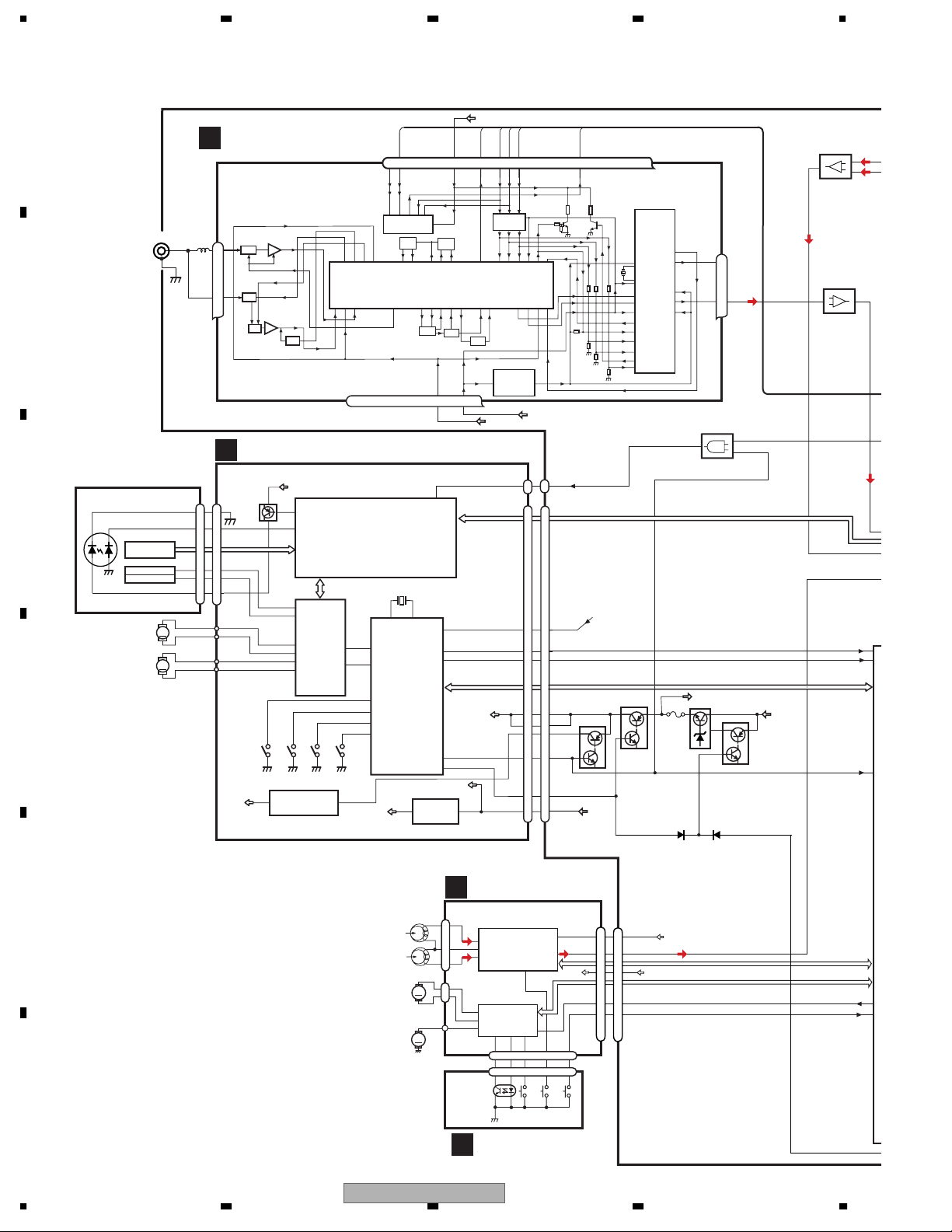
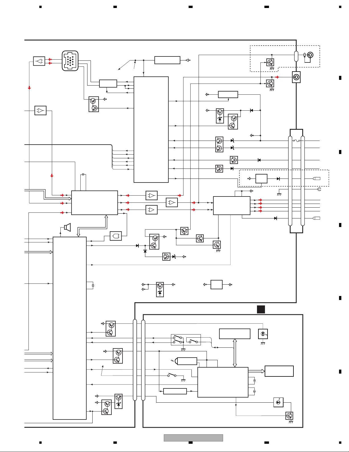
3. BLOCK DIAGRAM AND SCHEMATIC DIAGRAM
3.1 BLOCK DIAGRAM
A
TUNER AMP UNIT
A
FM/AM TUFNER UNIT
CN401
ANTENNA
1
2
B
PICKUP UNIT(P10)
(SERVICE)
LASER
C
DIODE
MONITOR
DIODE
M2
LOADING/CARRIAGE
MOTOR
HOLOGRAM
UNIT
FOCUS ACT.
TRACKING ACT.
M1
SPINDLE
MOTOR
M
M
D
AM ANT
1
FM ANT
3
C
CN101
LD-
15
15
MD
5
5
FOP
FOP
1
1
TOP
TOP
4
4
LD+
14
14
V3R3D
FMRF
ATT
ATT
FMRF
RF adj
ANT adj
CD CORE UNIT
V3R3D
142
Q101
AC,BD
E,F
LD
143
PD
FD,TD
12
FOP
13
TOP
16
SOP
15
SOM
18
LCOP
17
LCOM
BA5835FP
S904
S905
12EJ
8EJ
3
IC 203
NJM2885DL1-33
RF AMP, CD DECODER,
MP3 AND WMA DECODER,
DIGITAL SERVO/DATA PROCESSOR
DRIVER
IC 301
S903
DSCSNS
CD
SD,MD
LOEJ
CONT
HOME
S901
1
UPD63763GJ
22
9
3.3V REGULATOR
/TUNPCE2
7 6 13 5 10 9 8 11 14 18 19 20 21
WC
CE2
IC3 EEPROM
5.0V
OSC
MIXER, IF AMP
T51
RF_GND
DGND
BEGNDNCVCC
OSCGND
212 1522 16 4 17
34
X701
1312
X1
X2
MICRO
LRCKOK
IC 701
PE5454A
CD3VON
VDCONT
3V REGULATOR
3
XTAL
reset
EMPH
IC 703
IC 201
COMPUTER
53
LOEJ
47
CONT
32
12EJ
31
8EJ
30
DSCSNS
97
HOME
VD2
3VDD
S-812C33AUA-C2N
IC1
3.3V
LPF
CF52
15
44
37
46
49
ROM_VDD
VDD
SL
SL
CF51
3.3V
VDD_3.3
VCC8
DOUT,SCKO,LRCK
BRST,BRXEN,BSRQ
BDATA,BSCK
VD
VDD
2
TUNPCK
TUNPDO
DI
CK
IC5
←
5V 3.3V
IC4
3.3V 2.5V
CN902
MCK
CN901
LRCKOK
EMPH
VD
VD2
VDCONT
VDD
TUNPCE
CE1
←
DORA3V
1
15
9
13
3
4
2
1
19
5
2.5V
CN100
MCK
1
CN101
RESET
9
15
11
CPVD
21
CPVD
20
CPVD2
22
CD3VON
23
5
19
TUNPDI
NC
DO
C
LRCKOK
EMPH
BRST,BRXEN,BSRQ
BSIO,BSCK
Q802
Q827
VDCONT
VDD
NCNCNC
Q805
Q808
CD3VON
NC
2.5V
DET,
FM MPX
IC171
BUS
13
1
BUS
15
TA2050F
Rch
IC2
24
Lch
23
BUFFER
IC401
3
1
NJM4558MD
IC202
CKO2
2
4
MCK
1
CD3VON
TC7SH08FUS1
DOUT,LRCK,BCK
T
I
CS
51
50
E
BRST,BRXEN,BSRQ
FU800
PVD8
Q814
Q815
BU14V
BSIO,BSCK
47
C
DECK UNIT
D
E
FWD
L-ch
REV
L-ch
M2
SUB
MOTOR
M1
MAIN
MOTOR
F
16
1234
FH-P4200MP/XU/UC
CN252
1
5
4
CN254
2
M
1
CN255
M
EQ AMP
39
32
33
HA12228F
MECHANISM
DRIVER
5
IC351
2
1
PA2020B
8
CN253
3
3
CN256
Q101
EGN1004
REEL
SENSE
SENSOR UNIT
E
IC251
19
10
7
15 6
15 6
S102
MODE
CN251
15
TAPE+B
Lch
6
B.U
STBY
LOAD
17
4
4
S101
S103
LOAD
70µs
CN700
TAPE+B
4
4
3
3
20
20
19
19
11
11
TAPE Lch
stby
load
VCC8
BU14V
MSIN,DIRO,PLAY,MTL,NR,
POS,ES,CM,SC1,SC2
CSMDL
LCDPW
88
S
81
L
5678
IC171
13
1
15
TA2050F
BUFFER
IC401
3
NJM4558MD
BRST,BRXEN,BSRQ
BSIO,BSCK
GND
FLFL+
RLRL+
A
B
C
D
Q352
Q351
15
TPD1018F
UC
RL
PL
CN800
CN351
1
CN350
4
NON-FAD/SW L
FUSE
1
1
10A
3
3
5
5
88
4
4
22
10
10
12
12
9
9
11
11
6
6
FRONT L
ES,CN
B.UP
ACC
ILM
TELM
AANT
BREM
IP BUS
CN170
BUS+L
BUS-L
7
11
5
1
8
C
IP-BUS DRIVER
BUS-
5
IC170
BUS+
6
HA12240FP
8
Q170
BU14V
1
50
CKO2
84
CSMDL
51
50
TUNL
IPL
EMPH
BUZZER
22
PEE
BZ600
LIN4
83
LIN3
82
LIN2
Q171
X200
33.8888MHz
DIGITAL SOUND PROCESSOR/
ELECTRONIC VOLUME/
SOURCE SELECTOR
2
1
XO
XI
IC201
PM2009B
/DSPERR,/DSPOK,
/DSPACK,DSPOUT,
DSPCK,/DSPCS,/DSPRST
4
DSPIN
23
MUTE
1
SYSPW
SL
AOUT5
AOUT1
AOUT3
IFDO
IC200
TC7SET08FUS1
1
2
/TUNPCE2
TUNPCE
TUNPDI
TUNPDO
TUNPCK
24
5
14
70
/RESET
RESET
B
28
TX
TX
RX
IPPW
24
27
19
18
17
89
88
98
99
100
95
PREOUT L
RESET
RX
RX2
IPPW
ASENBO
SYSTEM
CONTROLLER
IC602(1/2)
PEG077A
TUNPCE2
TUNPCE1
TUNPDI
TUNPDO
TUNPCK
SL
NJM4558MD
3
FL
RL
3
NJM4558MD
MUTE DRIVER
1
S-80835CNUA-B8U
IC250
IC251
Q302
Q301
RESET
10
DSPPW
DALMON
bsens
asens
ISENS
TELIN
ANTPW
1
1
IC600
3
Q303
32
67
73
72
81
8
21
BU14V
2
1
IC252
NJM4558MD
MUTE
Q350
VDD
PREOUT L
BU14V
/BSENS
/ASENS
MUTE
Q300
FRONT L
VCC8
VDD
/ISENS
TELIN
8.4V REGULATOR
2
IC802
NJM2388F84
VDD REGULATOR
Q819
BACKUP SENSE
Q821
ACC SENSE
Q823
TEL SENSE
POWER AMP
14
FLIN
IC300
PAL007B
12
RLIN
STBY/MUTE
22 4
MUTE
Q304
SYSPW
Q824
Q820
ANTPW
VCC1/2
1
BU14V
ILM SENSE
BU14V
6
20
VCC3/4
BREM
25
AUTO ANTENNA
IC801
BU14V
23
FL-
21
FL+
3
RL-
5
RL+
CDPW
47
88
81
CD5VON
STBY
LOADSW
SYSTEM
CONTROLLER
IC 602(2/2)
PEG077A
IC1303
DORA3V
143
142
1
35
TUNER 3V REGULATOR
IC800
NJM2391DL1-33
KST4
5
4
KDT0
KDT0,KST4
3
1
134
DPDT
KYDT
reset
34
VDD
REM
KEY CONTROLLER
17
AVCC
LCD DRIVER/
IC1302
PEG079A
XOUT
ILMPW
ROT0
ROT1
SWVDD
DPDT
KYDT
LCDPW
11
X600
13
XIN
CN900
Q804
Q801
Q811
Q800
ILM+B
ROT0
ROT1
SWVDD
DPDT
/RESET
KYDT
BKLT+B
41
66
65
38
33
34
PVD8V
BU14V
20
BU14V
Q807
VDD
B
/RESET
Q813
D3.3V, A3.3V REGULATOR
D3V
A3V
CN1301
ILM+B
9
9
ROT0
6
6
ROT1
5
5
SWVDD
11
11
DPDT
8
8
RESET
4
4
KYDT
10
10
BKLT+B
7
7
Q817
1
2
REMOTE CONTROL SENSOR
OPT IN
S1301
RESET
RESET
2
IC1304
S-80842CNUA-B83
VCC8
VOLUME
Push:SOURCE
(Rotary Encoder)
S1220
3
TSOP4840SB1
FH-P4200MP/XU/UC
56
13
VCC8
S1201-1219
KEY MATRIX
125
7
KDT0-4,KST0-4
dim
OSC2
OSC1
XO
XI
B
ILLUMINATION
COM0-7,
SEG1-56
27
X1301
28
30
X1302
31
KEYBOARD UNIT
LCD
LCD BACKLIGHT
/DIM
Q1101
E
F
8
17
u
5
3
2
8
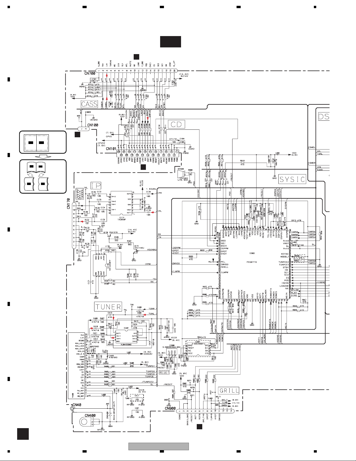
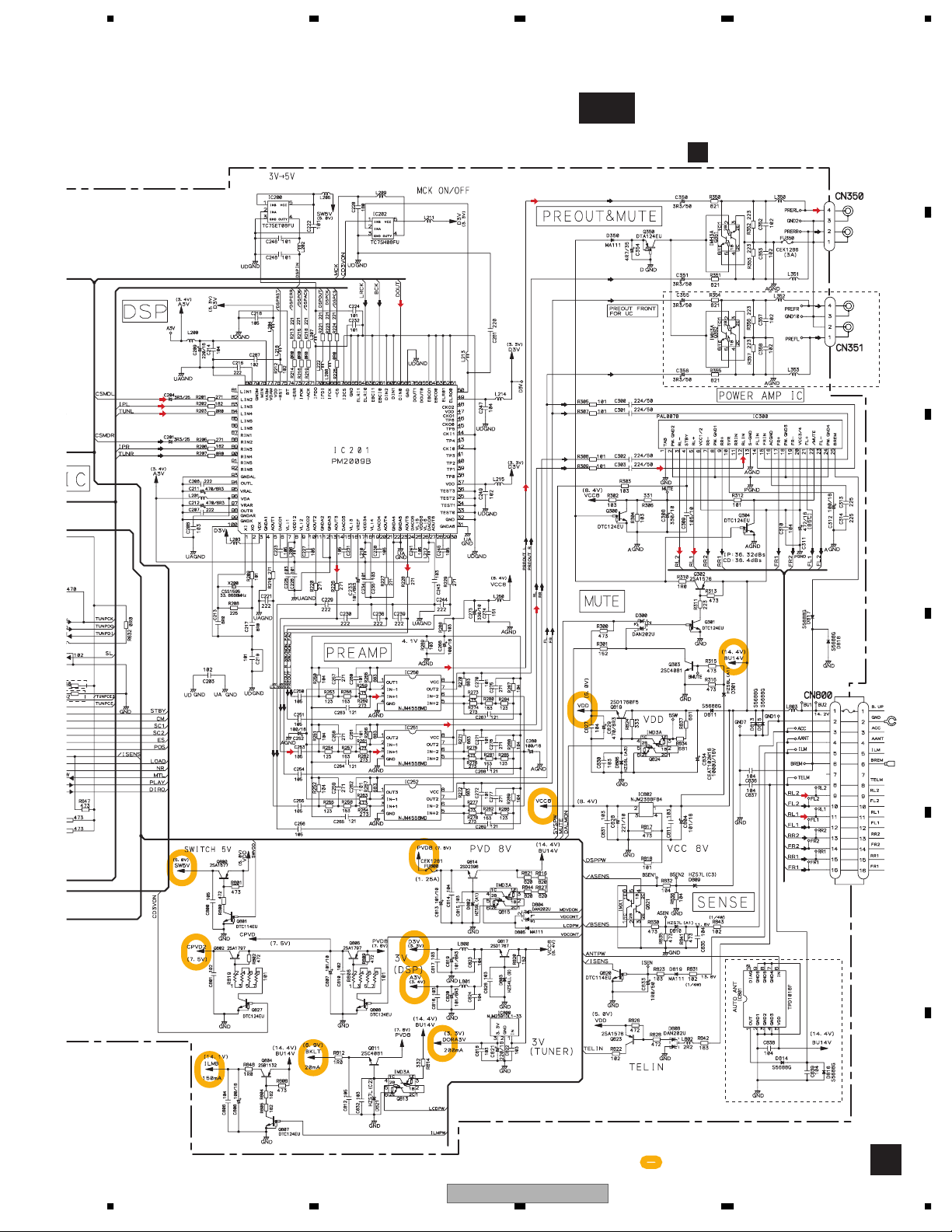
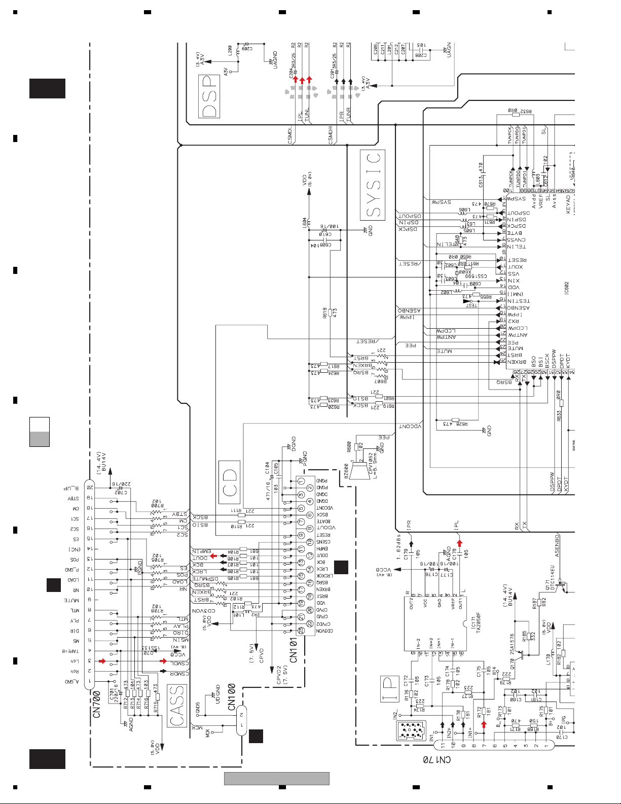
1234
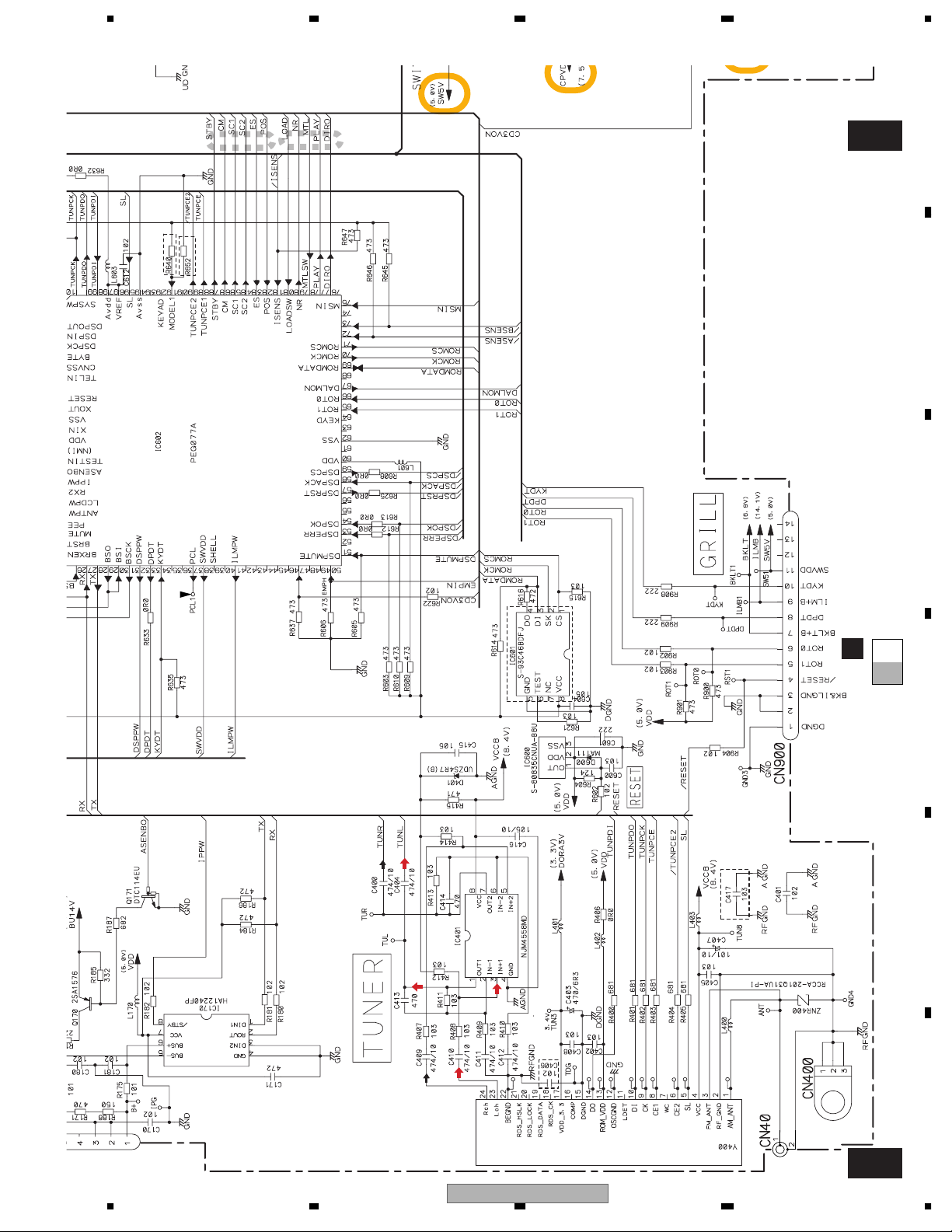
3.2 OVERALL CONNECTION DIAGRAM(GUIDE PAGE)
Note: When ordering service parts, be sure to refer to " EXPLODED VIEWS AND PARTS LIST" or
"ELECTRICAL PARTS LIST".
A
CN251
TAPE:-11.24dBs
D
B
CN902
C
C
A-a A-b
A-a
A-b
Large size
SCH diagram
Guide page
A-a
CN901
FM:-19.
AM: -
TAPE:-11.
IP-BUS: +1.
A-b
Detailed page
IP-BUS:+2.21dBs
AM(30%): -30dBs
FM(100%):-19.54dBs
CD5VON
NC
10.00MHz
SYSTEM CONTROLLER
asens
bsens
UC:473
ES,CN:104
UC:NM
ES,CN:473
A-a
C
D
E
UC
Not used
FM/AM TUNER UNIT
UC
FM/AM ANTENNA
F
CN1301
B
For resistors and capacitors in the circuit diagrams, their resistance val
capacitance values are expressed in codes:
Ex. *Resistors
Code Practical value
123 12k ohms
103 10k ohms
*Capacitors
Code Practical value
103 0.01uF
101/10 100uF/10V
A
18
1234
FH-P4200MP/XU/UC
5678
FM:-19.54dBs
AM: -30dBs
TAPE:-11.24dBs
IP-BUS: +1.82dBs
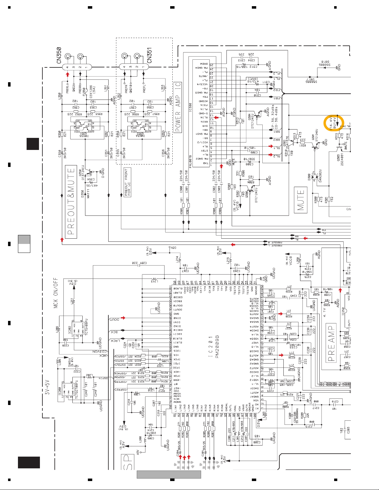
DSP, SOURCE SELECTOR,
ELECTRONIC VOLUME
A-b
TUNER AMP UNIT
A
>
REAR
L CH
REAR
R CH
FM: +3.96dBs
AM: -6.5dBs
CD: +10.4dBs
TAPE: -3.74dBs
IP-BUS:+10.32dBs
FRONT
R CH
FRONT
L CH
UC
A
B
C
UC:473
,CN:104
UC:NM
CN:473
grams, their resistance values or
FM: -2.94dBs
AM: -13.4dBs
CD: +3.5dBs
TAPE:-10.64dBs
IP-BUS: +3.42dBs
>
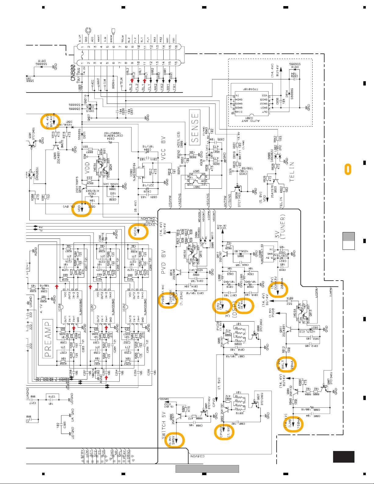
CD POWER
ILM POWER
BACK LIGHT POWER
FH-P4200MP/XU/UC
56
The > mark found on some component parts indicates
the importance of the safety factor of the part.
Therefore, when replacing, be sure to use parts of
identical designation.
: The power supply is shown with the marked box.
7
600µH
FM:+29.96dBs
AM: +19.5dBs
CD: +36.4dBs
TAPE:+22.26dBs
IP-BUS:+36.32dBs
ES,CN
8
FUSE
CEK1208
10A
>
D
E
F
A
19
1234
A
B
C
A-b
FM:-19.54dBs
AM: -30dBs
TAPE:-11.24dBs
IP-BUS: +1.82dBs
1
2
UC:473
ES,CN:104
10.00MHz
A-b
A-a
A-a
D
CN901
CN251
C
D
E
TAPE:-11.24dBs
F
A-a
20
CN902
C
IP-BUS:+2.21dBs
FH-P4200MP/XU/UC
1234
5678
A
UC:473
ES,CN:104
3
UC:NM
ES,CN:473
SYSTEM CONTROLLER
CD5VON
4
bsens
asens
NC
A-b
B
For resistors and capacitors in the circuit diagrams, their resistance values or
capacitance values are expressed in codes:
Ex. *Resistors
Code Practical value
123 12k ohms
103 10k ohms
*Capacitors
Code Practical value
103 0.01uF
101/10 100uF/10V
C
UC
Not used
UC
CN1301
B
A-b
A-a
A-a
D
E
AM(30%): -30dBs
FM(100%):-19.54dBs
FH-P4200MP/XU/UC
56
F
FM/AM TUNER UNIT
FM/AM ANTENNA
A-a
7
8
21
1234
A
FRONT
REAR
L CH
REAR
R CH
FM: +3.96dBs
CD: +10.4dBs
AM: -6.5dBs
TAPE: -3.74dBs
IP-BUS:+10.32dBs
>
FRONT
R CH
L CH
UC
B
TUNER AMP UNIT
A
C
A-b
A-a
D
E
ELECTRONIC VOLUME
DSP, SOURCE SELECTOR,
F
A-b
22
+1.82dBs
-30dBs
-19.54dBs
-11.24dBs
1
2
FH-P4200MP/XU/UC
1234
5678
A
>
10A
FUSE
CEK1208
ES,CN
FM:+29.96dBs
CD: +36.4dBs
AM: +19.5dBs
TAPE:+22.26dBs
600µH
IP-BUS:+36.32dBs
B
: The power supply is shown with the marked box.
The > mark found on some component parts indicates
the importance of the safety factor of the part.
Therefore, when replacing, be sure to use parts of
identical designation.
>
BACK LIGHT POWER
C
A-b
A-a
D
E
CD: +3.5dBs
FM: -2.94dBs
AM: -13.4dBs
TAPE:-10.64dBs
IP-BUS: +3.42dBs
3
4
FH-P4200MP/XU/UC
56
CD POWER
7
ILM POWER
values or
8
F
A-b
23
1234
R
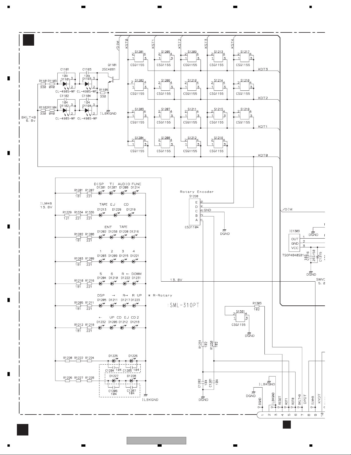
3.3 KEYBOARD UNIT
A
B
C
KEYBOARD UNIT
B
WHITE LED
1 BAND
6
3
TAPE
EJECT
CLOCK
ENT
AUDIO
FUNCTION
DSPDISP
54
VOLUME/
SOURCE
2
→
↓
←
↑
CD EJECT
REMOTE CONT
SENSOR
D
GREEN LED
E
D1225-D1228
UC ,ES :SML-310PT (GREEN LED)
CN:CL-190UB2-X (BLUE LED)
UC ,ES : 271 331 331
CN : 181 181 221
UC ,ES : 271 331 331
CN : 181 181 221
RESET
ES,CN
F
CN900
A
B
24
1234
FH-P4200MP/XU/UC
5678
A
B
OTE CONTROL
SENSOR
LCD DRIVER,
KEY CONTROLLER
32.768kHz
10.0MHz
C
D
E
RESET IC
CN900
CN1301
FH-P4200MP/XU/UC
56
F
B
7
8
25
1234
Y
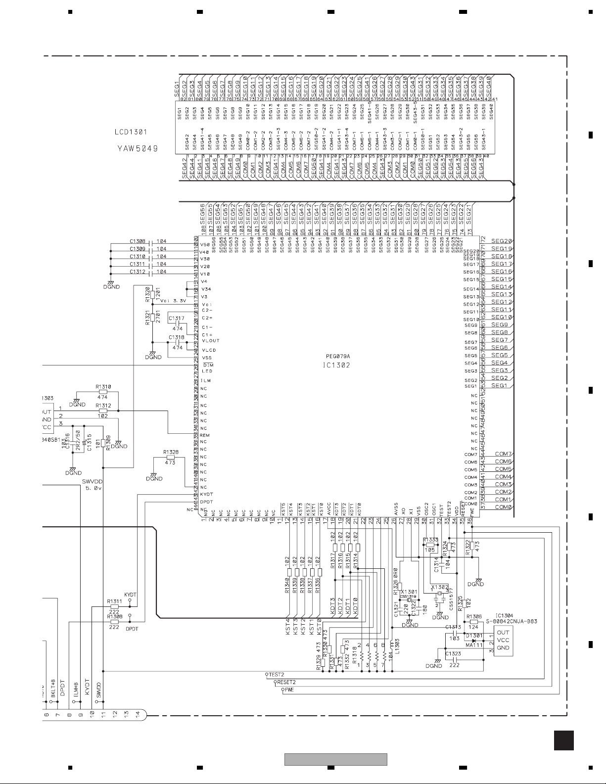
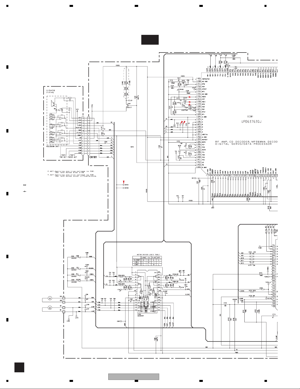
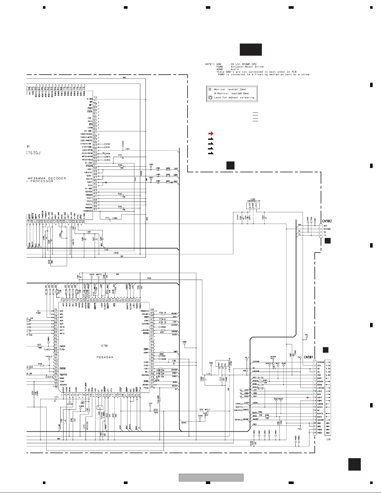
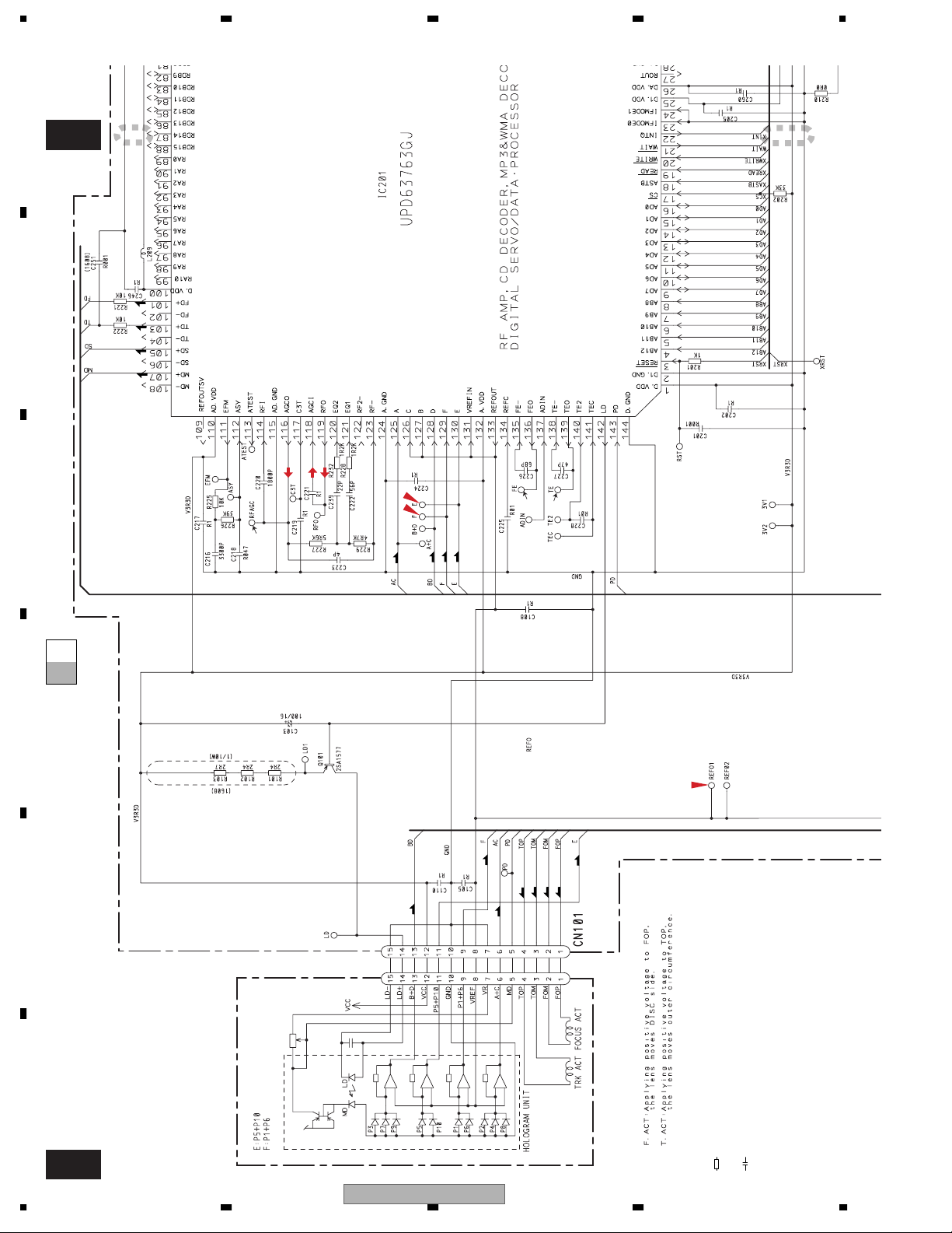
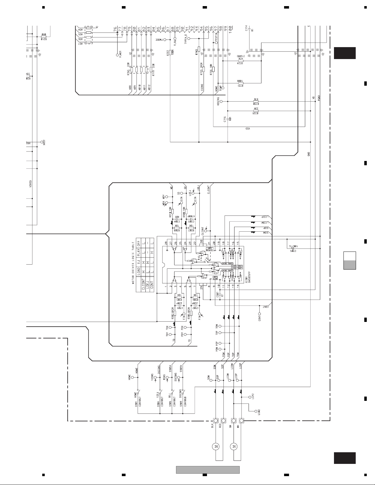
3.4 CD MECHANISM MODULE
A
PICKUP UNIT(P10)
(SERVICE)
B
C-a
F
T
C
S
%
F
T
F
T
T
F
F
T
F
F
T
T
#
@
C
NOTE :
Symbol indicates a resistor.
No differentiation is made between chip resistors and
discrete resistors.
Symbol indicates a capacitor.
No differentiation is made between chip capacitors and
discrete capacitors.
The > mark found on some component parts indicates
the importance of the safety factor of the part.
Therefore, when replacing, be sure to use parts of
identical designation.
Decimal points for resistor
and capacitor fixed values
are expressed as :
←
2.2 2R2
←
0.022 R022
D
3
2
1
E
M1 CXC4440
SPINDLE MOTOR
M2 CXB8933
LOADING
/CARRIAGE
MOTOR
S
S
C
C
T
9
F
0
F
F
T
T
CD DRIVER
$
S
7
C
8
4
5
S
C
S
C
100K
T
F
C
26
1234
FH-P4200MP/XU/UC
5678
A
C-b
SWITCHES:
CD CORE UNIT
S901:HOME SWITCH..........ON-OFF
ras
!
220
220
220
S903:DSCSNS SWITCH......ON-OFF
S904:12EJ SWITCH.............ON-OFF
S905:8EJ SWITCH...............ON-OFF
The underlined indicates the switch position.
SIGNAL LINE
F
FOCUS SERVO LINE
T
TRACKING SERVO LINE
C
CARRIAGE SERVO LINE
S
SPINDLE SERVO LINE
CD CORE UNIT
C
3.3V REGULATOR
B
C
220P
A
CN100
D
SRAMLEVEL2
MICRO COMPUTER
SRAMLEVEL1
SRAMLEVEL0
100K
TYPE_A/D
1K
1K
3V REGULATOR
LRCKOKEMPH
(
6
)
A
CN101
E
LRCK
&
*
SCK
^
DOUT
FH-P4200MP/XU/UC
56
⁄
F
C
7
8
27
A
C-b
1234
1
2
B
C
F
T
C
S
#
@
%
T
T
F
F
C-b
A-a
C-a
D
E
F
C-a
28
PICKUP UNIT(P10)
(SERVICE)
T
T
F
F
TFF
T
←
←
Decimal points for resistor
and capacitor fixed values
are expressed as :
2.2 2R2
0.022 R022
Symbol indicates a resistor.
No differentiation is made between chip resistors and
discrete resistors.
Symbol indicates a capacitor.
No differentiation is made between chip capacitors and
discrete capacitors.
The > mark found on some component parts indicates
the importance of the safety factor of the part.
Therefore, when replacing, be sure to use parts of
NOTE :
identical designation.
FH-P4200MP/XU/UC
1234
Th
>
k
f
d
t
t
i
di
t
5678
A
2
3 4
100K
5 6
C-b
B
4
C
7
$
S
T
8
C
T
C
S
S
CD DRIVER
C-b
A-a
C-a
D
C
9
F
5
F
T
F
0
E
2
es
ca
n
s
par
on some componen
oun
mar
e
the importance of the safety factor of the part.
Therefore, when replacing, be sure to use parts of
identical designation.
56
3
1
S
S
M1 CXC4440
SPINDLE MOTOR
FH-P4200MP/XU/UC
C
C
LOADING
/CARRIAGE
M2 CXB8933
7
MOTOR
8
F
C-a
29
 Loading...