

Page 1
DVD PLAYER
DV-K301C
THIS MANUAL IS APPLICABLE TO THE FOLLOWING MODEL(S) AND TYPE(S).
Type
RL AC110-127/220-240V 3 Automatic select
RAM AC110-127/220-240V 6 Automatic select
Model
DV-K301C
Power Requirement Region No.
The voltage can be converted by
the following method.
ORDER NO.
RRV2050
• Refer to the service guide RRV2004 for DV-515.
CONTENTS
1. SAFETY INFORMATION
2. EXPLODED VIEWS AND PARTS LIST
3. SCHEMATIC DIAGRAM
4. PCB CONNECTION DIAGRAM
5. PCB PARTS LIST
6. ADJUSTMENT
PIONEER ELECTRONIC CORPORATION 4-1, Meguro 1-Chome, Meguro-ku, Tokyo 153-8654, Japan
PIONEER ELECTRONICS SERVICE, INC. P.O. Box 1760, Long Beach, CA 90801-1760, U.S.A.
PIONEER ELECTRONIC (EUROPE) N.V. Haven 1087, Keetberglaan 1, 9120 Melsele, Belgium
PIONEER ELECTRONICS ASIACENTRE PTE. LTD. 253 Alexandra Road, #04-01, Singapore 159936
c
PIONEER ELECTRONIC CORPORATION 1998
...............................................
....................................................
......................................
................
.....................................
..........................
10
24
34
39
2
3
7. GENERAL INFORMATION
7.1 IC
7.2 DISASSEMBLY
7.3 BLOCK DIAGRAM
8. PANEL FACILITIES AND SPECIFICATIONS
..................................................................
............................................
........................................
T – IZE NOV. 1998 Printed in Japan
................................
....
41
41
42
48
49
Page 2

DV-K301C
1. SAFETY INFORMATION
This service manual is intended for qualified service technicians ; it is not meant for the casual do-ityourselfer. Qualified technicians have the necessary test equipment and tools, and have been trained
to properly and safely repair complex products such as those covered by this manual.
Improperly performed repairs can adversely affect the safety and reliability of the product and may
void the warranty. If you are not qualified to perform the repair of this product properly and safely, you
should not risk trying to do so and refer the repair to a qualified service technician.
IMPORTANT
THIS PIONEER APPARATUS CONTAINS
LASER OF CLASS 1.
SERVICING OPERATION OF THE APPARATUS
SHOULD BE DONE BY A SPECIALLY
INSTRUCTED PERSON.
LASER DIODE CHARACTERISTICS
FOR DVD : MAXIMUM OUTPUT POWER : 7 mw
FOR CD : MAXIMUM OUTPUT POWER : 5mW
WAVELENGTH : 650 nm
WAVELENGTH : 780 – 785 nm
Additional Laser Caution
1. Inside detection switch (S201 on the SMEB assy) and loadingstatus detection switch (S9503 on the MOT OR assy) are detected
by the microprocessor (IC501 in the DVDM assy).
• To permit the laser diode to oscillate, it is required to set the
inside detection switch for the inside position (S201 : ON) and to
set the loading-status detection switch for the clamp position (the
center terminal of S9503 is shorted to +5V). The 650 nm laser
diode for DVD oscillation will contin ue if pin 19 of IC101 is shorted
to +5V (fault condition) in the DVDM assy.
The 780 nm laser diode for CD oscillates if pin 20 of IC101 is
shorted to +5V in the DVDM assy.
In the test mode ∗ , the laser diode oscillates when microprocessor detects a PLAY signal, or when the PLAY key is pressed
(S132 ON in the FLKB assy), with the above requirements satisfied.
2. When the cover is open, close viewing through the objective lens
with the naked eye will cause exposure to the laser beam.
∗ : Refer to the service guide RRV2004.
2
Page 3
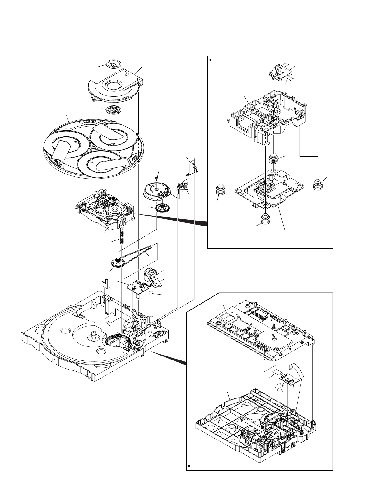
2. EXPLODED VIEWS AND PARTS LIST
NOTES:• Parts marked by "NSP" are generally unavailable because they are not in our Master Spare Parts List.
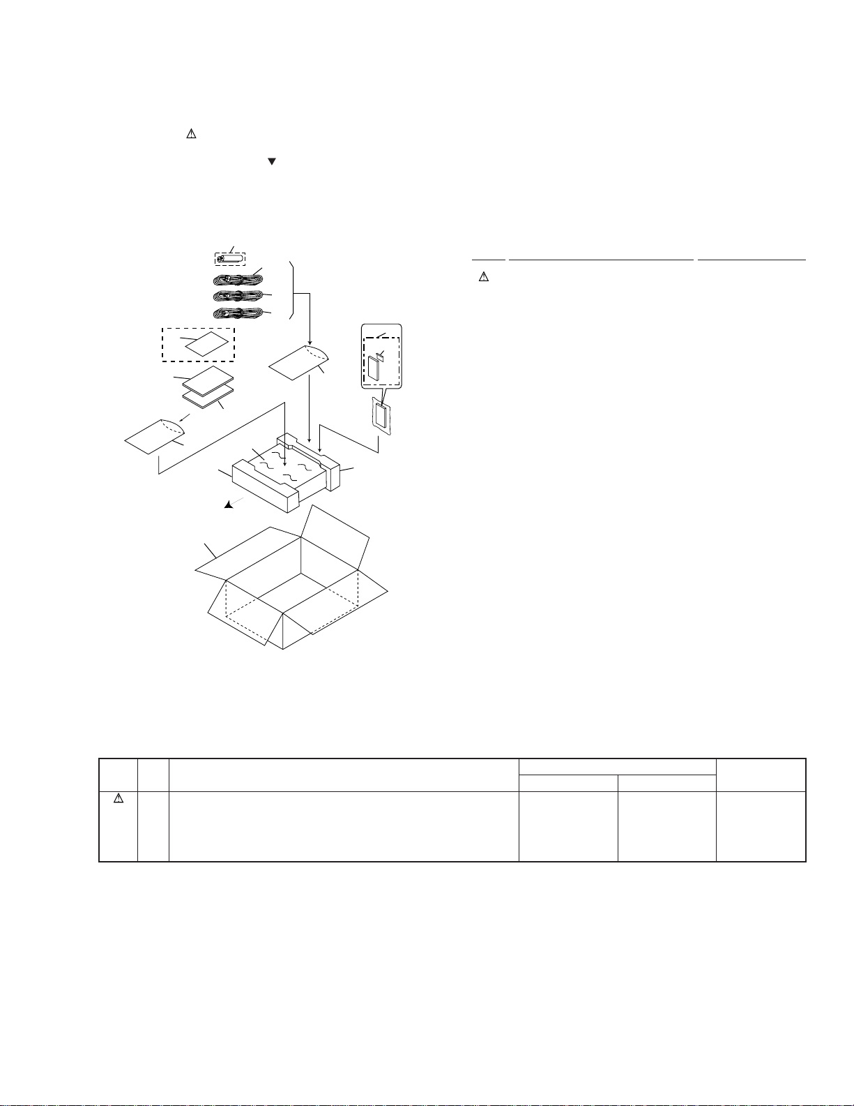
2.1 PACKING
The mark found on some component parts indicates the importance of the safety factor of the part.
•
Therefore, when replacing, be sure to use parts of identical designation.
Screws adjacent to mark on the product are used for disassembly.
•
DV-K301C
13
15
8
11
FRONT
6
4
RAM Type
Only
5
7
(1) PACKING PARTS LIST
3
2
1
9
10
8
12
Mark No. Description Part No.
1 Power Cord See Contrast table (2)
2 Video Cord (L = 1.5m) VDE1048
3 Audio Cord (L = 1.5m) VDE1033
NSP 4 Dry Cell Battery (R6P, AA) VEM-013
5 Operating Instructions VRB1206
(English)
6 Packing Case See Contrast table (2)
7 Sheet RHX1006
8 Polyethylene Bag Z21-038
(0.03×230×340)
9 Remote Control Unit VXX2597
(CU-DV023)
10 Battery Cover AZA7204
11 Pad F VHA1224
12 Pad R VHA1225
13 Operating Instructions See Contrast table (2)
14 • • • • •
NSP 15 Warranty Card See Contrast table (2)
(2) CONTRAST TABLE
DV-K301C/RL and RAM are constructed the same except for the following :
Mark No. Symbol and Description
1 Power Cord ADG1127 ADG7017
6 Packing Case VHG1766 VHG1763
13 Operating Instructions (Trad. Chinese Language) VRC1082 Not used
13 Operating Instructions (Simp. Chinese Language) Not used VRC1081
NSP 15 Warranty Card Not used ARY7028
DV-K301C/RL DV-K301C/RAM
Part No.
Remarks
3
Page 4
DV-K301C
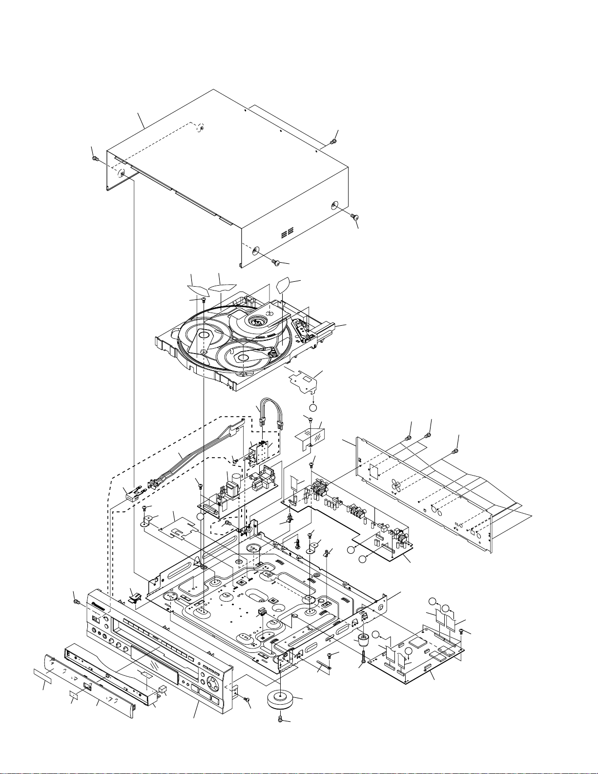
2.2 EXTERIOR SECTION
10
31
30
31
39
30
RL Type Only
40
30
17
16
14(1/3)
30
C
14(2/3)
42
3
30
38
37
41
22
20
31
36
14(3/3)
D
30
8
30
4
Refer to
"2.3 $M MECH DVD ASSY".
13
35
11
16
21
B
A
30
30
30
2
18
15
28
27
Refer to
"2.4 FRONT PANEL SECTION".
19
33
30
25
23
30
24
32
12
B
A
6
C
7
D
9
1
5
30
34
26
33
29
4
Page 5
(1) EXTERIOR SECTION PARTS LIST
Mark No. Description Part No.
DV-K301C
Mark No. Description Part No.
1 DVDM Assy VWS1366
2 KRJB Assy See Contrast table (2)
3 POWER SUPPLY Assy VWR1306
NSP 4 $M MECH DVD Assy VWT1154
5 Flexible Cable (26P) VDA1695
(DVDM CN9020 ↔ KRJB CN901)
6 Flexible Cable (14P) VDA1697
(DVDM CN9030 ↔ KRJB CN501)
7 Flexible Cable (26P) VDA1705
(DVDM CN110 ↔ POWER SUPPLY CN103)
8 Flexible Cable (10P) VDA1706
(KRJB CN401 ↔ MIJB CN402)
9 Flexible Cable (14P) VDA1707
(DVDM CN602 ↔ FLKY CN101)
10 Bonnet S VXX2617
11 Rear Panel See Contrast table (2)
NSP 12 Chassis VNA1979
13 FFC Guard VEC2021
14 Tray Number Label VRW1759
15 Tray Label VRW1628
NSP 16 PCB Base RNE1221
17 FFC Binder VEC2020
18 Flat Cable Clip VEC2018
19 PCB Hinge VEC1174
NSP 20 PCB Holder PNW2029
NSP 21 Card Spacer DEC1770
NSP 22 PCB Holder PNW2100
23 Cord Clamper RNH-184
24 Insulator Assy VXA1638
25 Insulator Assy VXA2356
26 DVD Plate VAM1080
27 Tray Panel Base VNK4382
28 Tray Panel Cushion VEB1297
29 Tray Panel VNK4359
30 Screw BBZ30P080FMC
31 Screw BCZ40P060FNI
32 Screw BBZ30P180FMC
33 Screw IBZ30P080FMC
NSP 34 Getter VRW1748
35 IC Guard VEC2019
36 Nyron Rivet VEC2040
NSP 37 Housing Assy See Contrast table (2)
NSP 38 Power Holder See Contrast table (2)
39 Power Button See Contrast table (2)
40 PW Joint See Contrast table (2)
NSP 41 MSWB Assy See Contrast table (2)
42 Screw See Contrast table (2)
(2) CONTRAST TABLE
DV-K301C/RL and RAM are constructed the same except for the following :
Mark No. Symbol and Description
2 KRJB Assy VWV1625 VWV1654
11 Rear Panel VNA2018 VNA2017
NSP 37 Housing Assy (POWER SUPPLY CN2 ↔ MSWB CN10) VKP2194 Not used
NSP 37 Housing Assy (POWER SUPPLY CN2 Short circuit) Not used VKP2189
NSP 38 Power Holder VNE2123 Not used
39 Power Button VNK4159 Not used
40 PW Joint VNK4364 Not used
NSP 41 MSWB Assy VWG1997 Not used
42 Screw PMB30P080FZK Not used
DV-K301C/RL DV-K301C/RAM
Part No.
Remarks
5
Page 6
DV-K301C
2.3 $M MECH DVD ASSY
21
25
Bottom View
24
17
23
19
(×2)
27
16
29
14
15
8
11
10
10
7
9
9
4
Refer to
"2.5 SERVO MECH ASSY".
13
20
30
28
18
3
22
6
26
2
5
1
Bottom View
6
Page 7
$M MECH DVD ASSY PARTS LIST
Mark No. Description Part No.
NSP 1 SW Assy VWG2002
NSP 2 TRADE Assy VWG2003
NSP 3 MOTOR Assy VWG2004
4 SERVO MECH Assy-S VXX2606
5 Flexible Cable (8P) VDA1702
(TRADE CN9001 ↔ SMEB CN202)
6 Flexible Cable (13P) VDA1703
(TRADE CN9002 ↔ DVDM CN103)
7 Flexible Cable (24P) VDA1704
(Pickup Assy ↔ DVDM CN120)
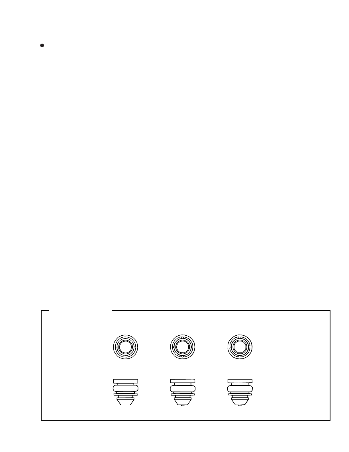
8 Servo Spring ABH7126
9 Float Rubber C VEB1299
10 Float Rubber B AEB7066
11 Belt AEB7072
12 Main Cam ANW7093
13 Gear Pulley ANW7094
14 Lock Lever ANW7095
15 Planet Gear ANW7096
16 Actuator ANW7097
17 Rotary Tray ANW7113
18 Motor Pulley PNW1634
DV-K301C
19 SB Spacer VEC2046
20 LT Spacer VEC2047
21 Clamper Plate VNE2162
22 Mecha Base VNK4304
23 Clamper VNK1738
24 FFC Holder VNL1803
25 Clamper Holder VNL1804
26 Loading Tray XNW3002
27 Servo Base XNW3003
28 Slider Motor (LOADING) VXM1033
29 Screw IPZ30P080FMC
30 Shaft Press Rubber VEB1300
Detail of Float Rubber
(No.9, No.10)
AEB7066
VEB1299 VEB1301
(Soft) (Hard) (Hard)
7
Page 8
DV-K301C
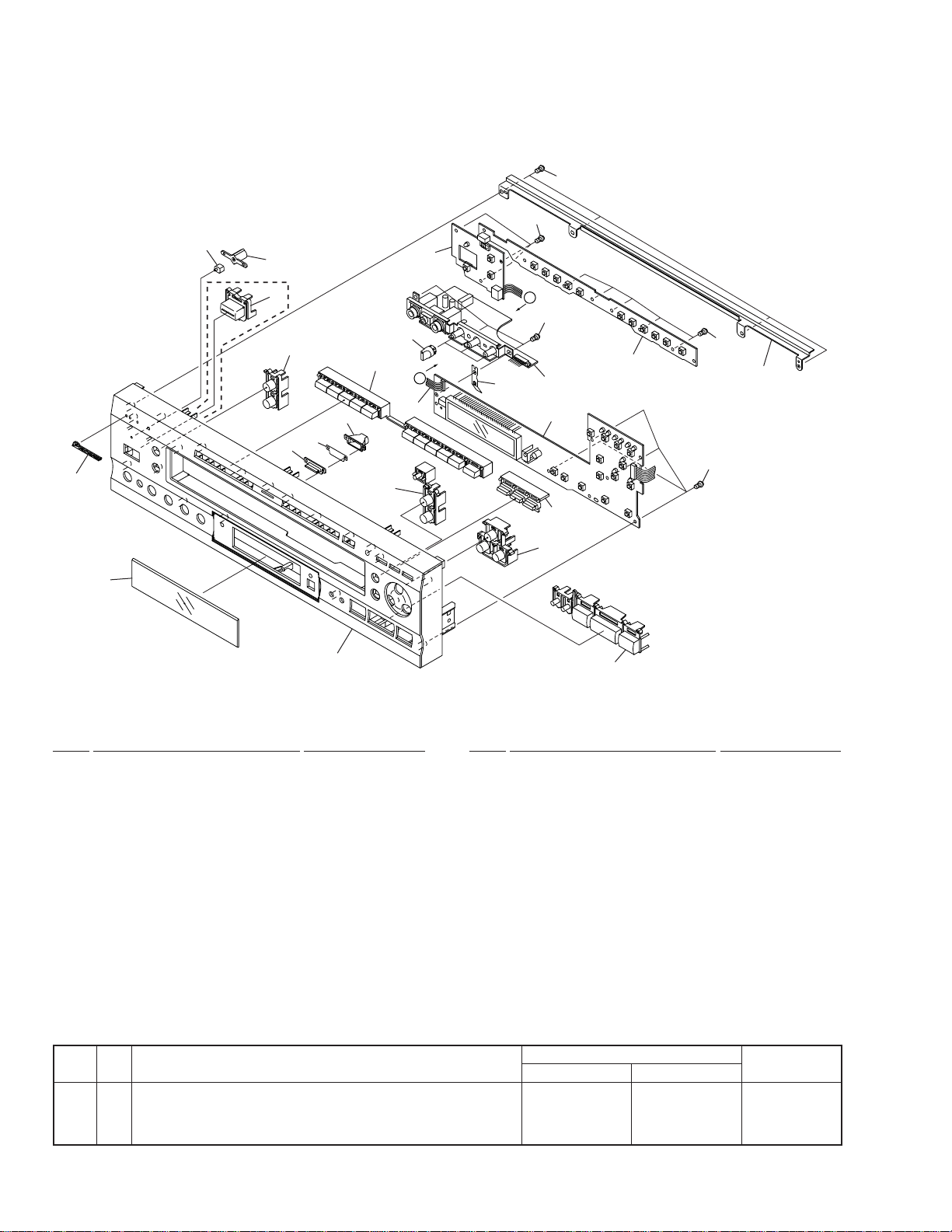
2.4 FRONT PANEL SECTION
23
23
7
6
22
15
11
13
RAM Type
Only
19(2/2)
16
9
14
19(1/2)
20
17
3
A
23
23
2
A
5
8
4
1
23
12
18
21
10
(1) FRONT PANEL SECTION PARTS LIST
Mark No. Description Part No. Mark No. Description Part No.
NSP 2 KYLB Assy VWG2014
1 FLKY Assy See Contrast table (2)
NSP 3 PWSB Assy See Contrast table (2)
4 MICB Assy VWV1637
5 Flexible Cable (6P) VDA1708
(FLKY CN103 ↔ PWSB CN301)
6 Name Plate G PAM1779
7 LED Lens PNW2019
8 Earth Plate VBK1080
9 Illumination Holder VNK4265
10 FP Angle VNE2159
11 PW Button See Contrast table (2)
12 Light Key VNK4261
13 Illumination Lens VNK4264
14 Illumination Filter VEC1983
15 Lens Holder VNK4266
16 11 Key VNK4271
17 Volume Knob VNK4279
18 Direct Key VNK4360
19 5 Key VNK4362
20 Front Panel See Contrast table (2)
21 Main Key VNK4361
22 FL Lens VNK4363
23 Screw BBZ30P080FMC
(2) CONTRAST TABLE
DV-K301C/RL and RAM are constructed the same except for the following :
Mark No. Symbol and Description
1 FLKY Assy VWG2011 VWG2010
NSP 3 PWSB Assy VWG2016 VWG2015
11 PW Button Not used VNK4059
20 Front Panel VNK4381 VNK4358
DV-K301C/RL DV-K301C/RAM
Part No.
Remarks
8
Page 9
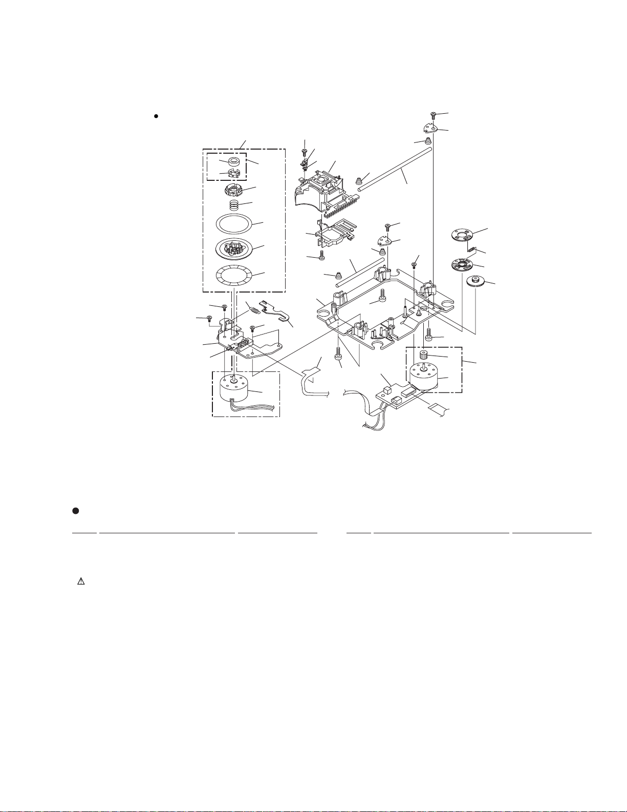
2.5 SERVO MECH ASSY
DV-K301C
Top View
37
17
31
24
30
16
37
18
26
11
25
27
7
29
36
3
22
33
21
33
23
10
28
15
10
5
10
13
37
10
14
7
2
7
18
32
1
35
34
19
8
6
20
12
9
37
4
SERVO MECH ASSY PARTS LIST
Mark No. Description Part No. Mark No. Description Part No.
NSP 1 SMEB Assy VWG1968
NSP 2 FGSB Assy VWG2009
3 Motor (CARRIAGE) VXM1074
4 Motor (SPINDLE) VXM1075
5 Pickup Assy VWY1050
6 Table Sheet DEC2040
7 Screw VBA1058
8 Centering Spring VBH1278
9 Hook Spring VBH1291
10 Skew Spring VBH1303
11 Gear Spring VBH1308
NSP 12 Reflected Sheet VEC1959
13 Guide Bar VLL1504
14 Sub Guide Bar VLL1505
15 Hold Spring VNC1017
NSP 16 Magnet Holder VNE2070
NSP 17 Motor Base VNE2154
NSP 18 Cover VNE2155
19 Centering Ring VNL1746
NSP 20 Disc Table VNL1747
NSP 30 Magnet VYM1024
21 Hook VNL1770
22 FFC Holder VNL1802
23 Mechanism Base VNL1806
24 FG Holder VNL1807
25 Gear A VNL1808
26 Gear B VNL1809
27 Gear C VNL1810
28 Slider VNL1811
29 Gear D VNL1814
31 Screw JFZ17P025FZK
32 Screw JGZ17P028FMC
33 Screw VBA1051
34 Magnet Holder Assy VXX2507
35 Spindle Motor Assy VXX2604
36 Carriage Motor Assy VXX2605
37 Screw PBA1069
9
Page 10
1
23
4
DV-K301C
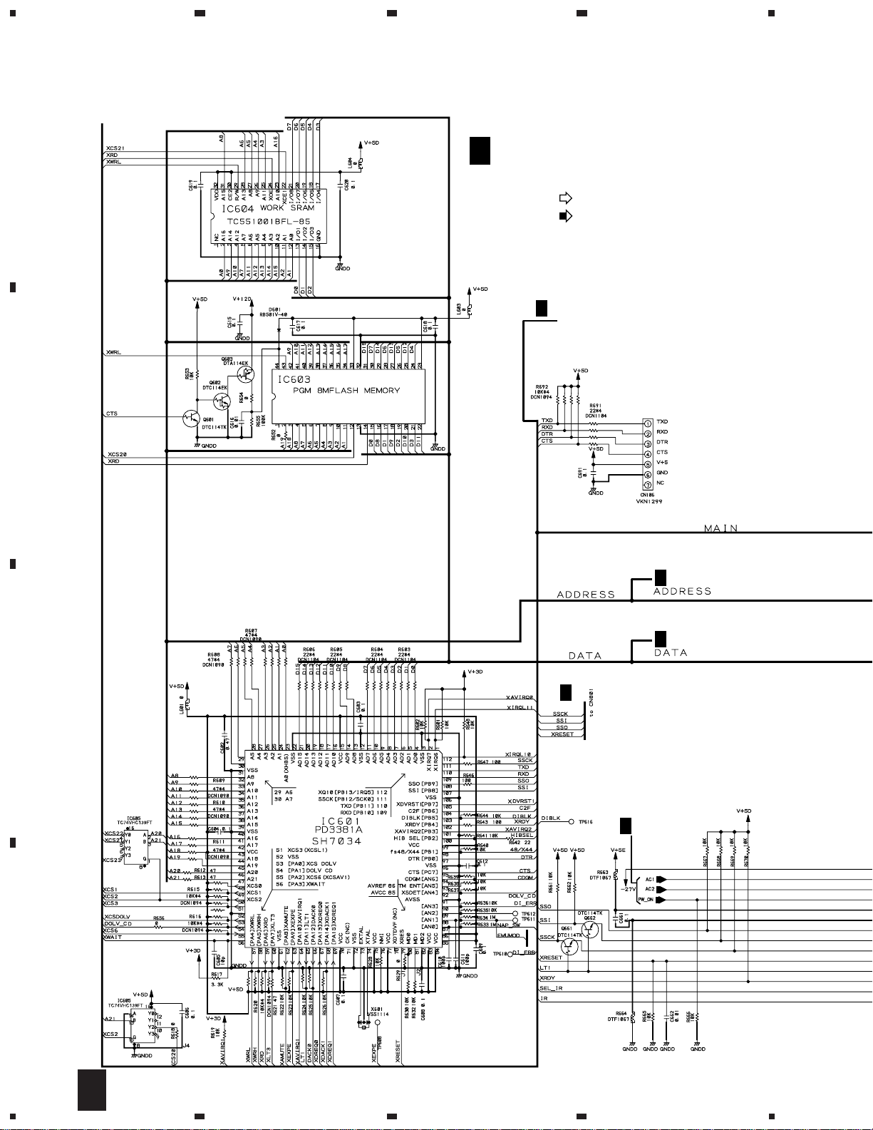
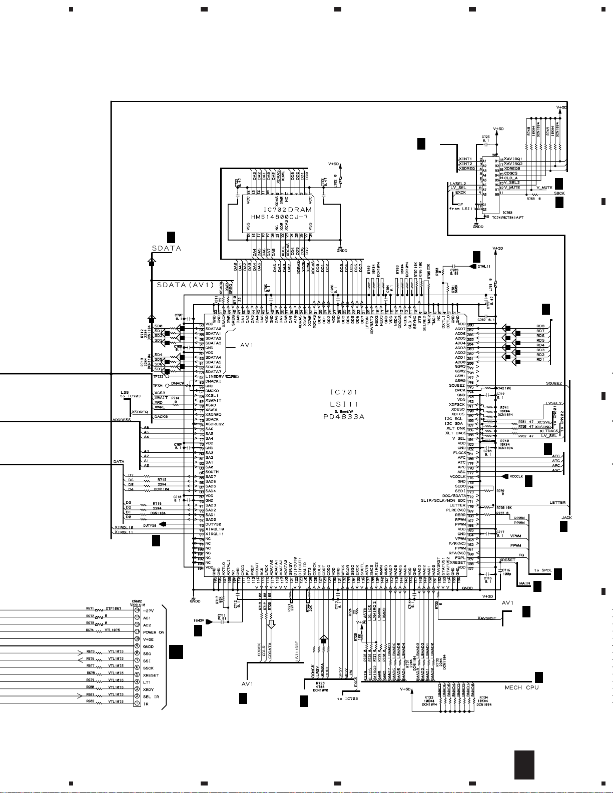
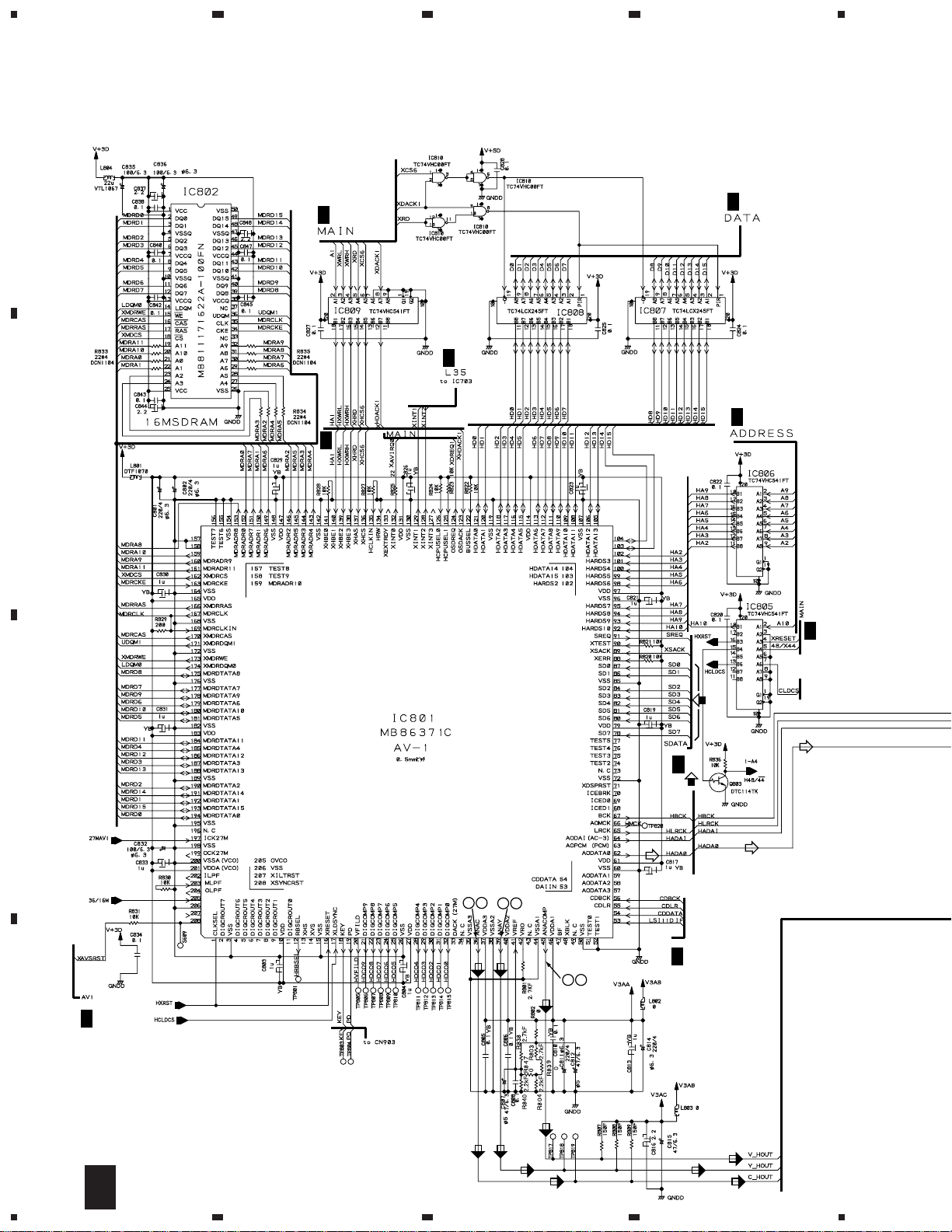
3. SCHEMATIC DIAGRAM
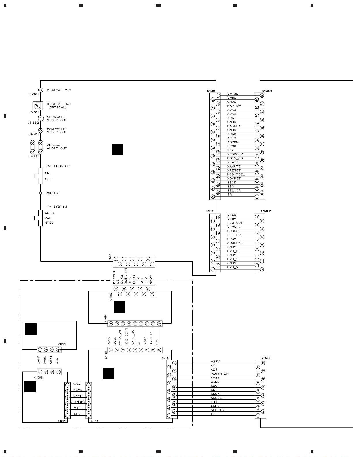
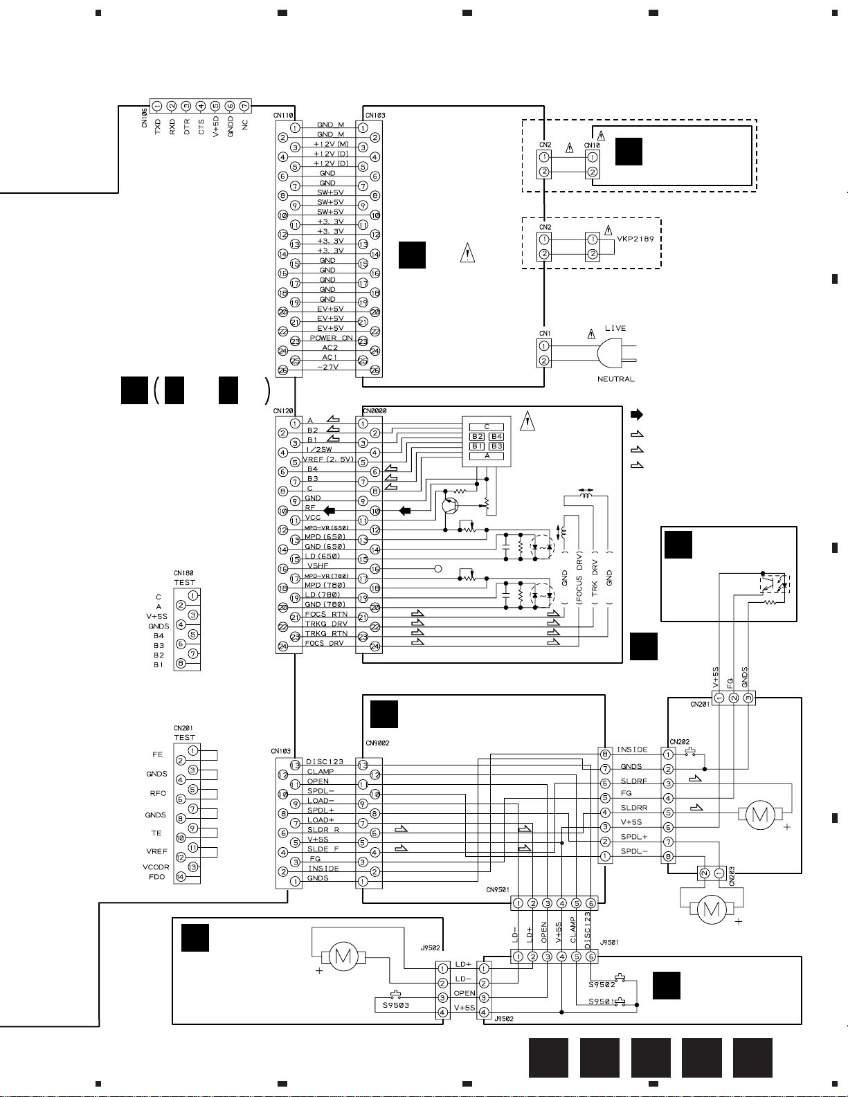
3.1 OVERALL WIRING DIAGRAM, SW, TRADE, MOTOR, SMEB
A
and FGSB ASSEMBLIES
Note : When ordering service parts, be sure to refer to "EXPLODED VIEWS and PARTS LIST" or "PCB PARTS LIST".
K
KRJB ASSY
B
(RL : VWV1625)
(RAM : VWV1654)
C
FRPB ASSY
(RL : VWM1883)
(RAM : VWM1882)
KYLB ASSY
H
(VWG2014)
MICB ASSY
J
(VWV1637)
G
I
D
PWSB ASSY
(RL : VWG2016)
(RAM : VWG2015)
10
1234
FLKY ASSY
(RL : VWG2011)
(RAM : VWG2010)
Page 11
5
678
DV-K301C
for RS232C
F
F
1/3-
DVDM ASSY
(VWS1366)
F
3/3
(T)
(F)
(F)
L
POWER SUPPLY
ASSY
(VWR1306)
(F)
(F)
(T)
(F)
(T)
(T)
(F)
TRADE ASSY
B
(VWG2003)
SLW13R-1C7
AC POWER CORD
RL : ADG1127
RAM : ADG7017
PICKUP
ASSY
(VWY1050)
(F)
(T)
(T)
(F)
CN9001
SLW8R-1C7
MSWB ASSY
M
(VWG1997)
RL TYPE ONLY
RAM TYPE ONLY
AC110-127V/220-240V
50/60Hz
: RF SIGNAL ROUTE
(F)
: FOCUS SERVO LOOP LINE
(T)
: TRACKING SERVO LOOP LINE
(S)
: SLIDER SERVO LOOP LINE
FGSB ASSY
E
(VWG2009)
D
SMEB ASSY
(VWG1968)
52044-0345
VKN1212
IC101
TLP910(O)
R101
680
A
B
C
C
MOTOR ASSY
(VWG2004)
5
LOADING MOTOR
VXM1033
(S)
(S)
6
D20PWW0405E
52147-0610
(S)
(S)
(S)
(S)
SPINDLE MOTOR ASSY
D20PWY0610E
A
7
CARRIAGE MOTOR
ASSY
VXX2605
VXX2604
SW ASSY
(VWG2002)
EDCBA
8
D
11
Page 12
1
DV-K301C
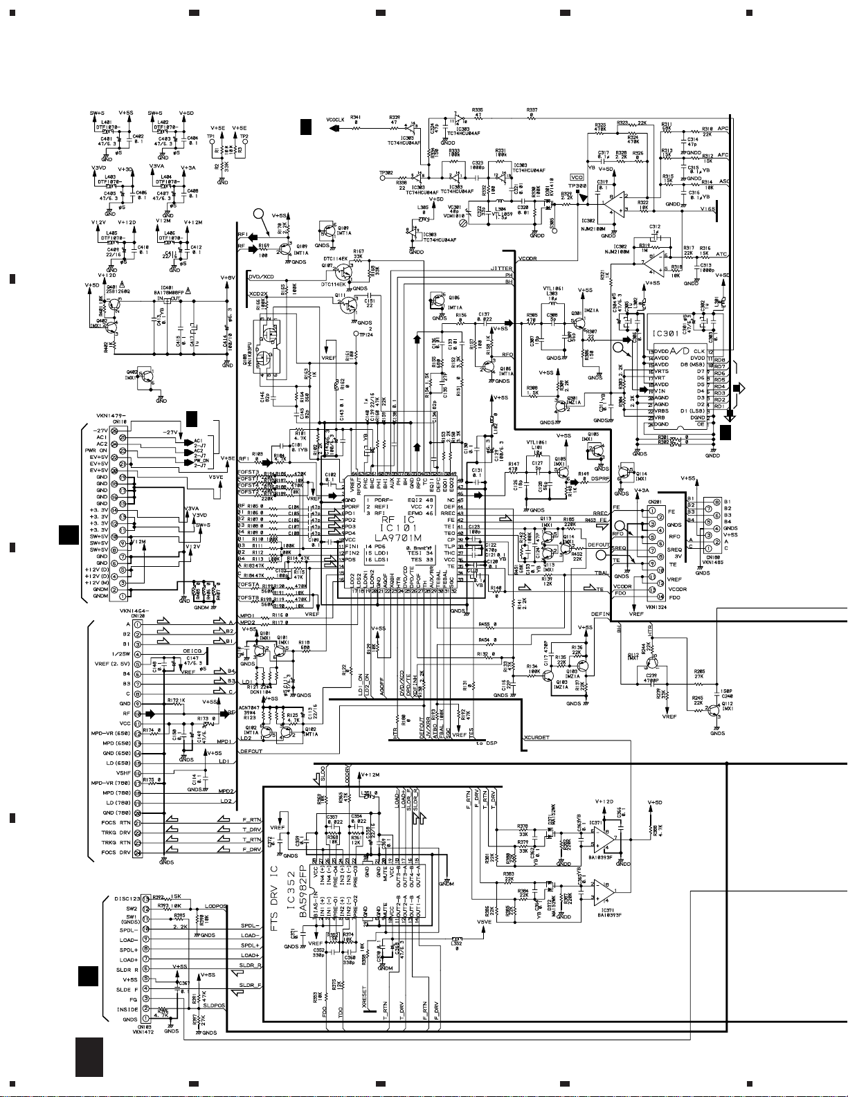
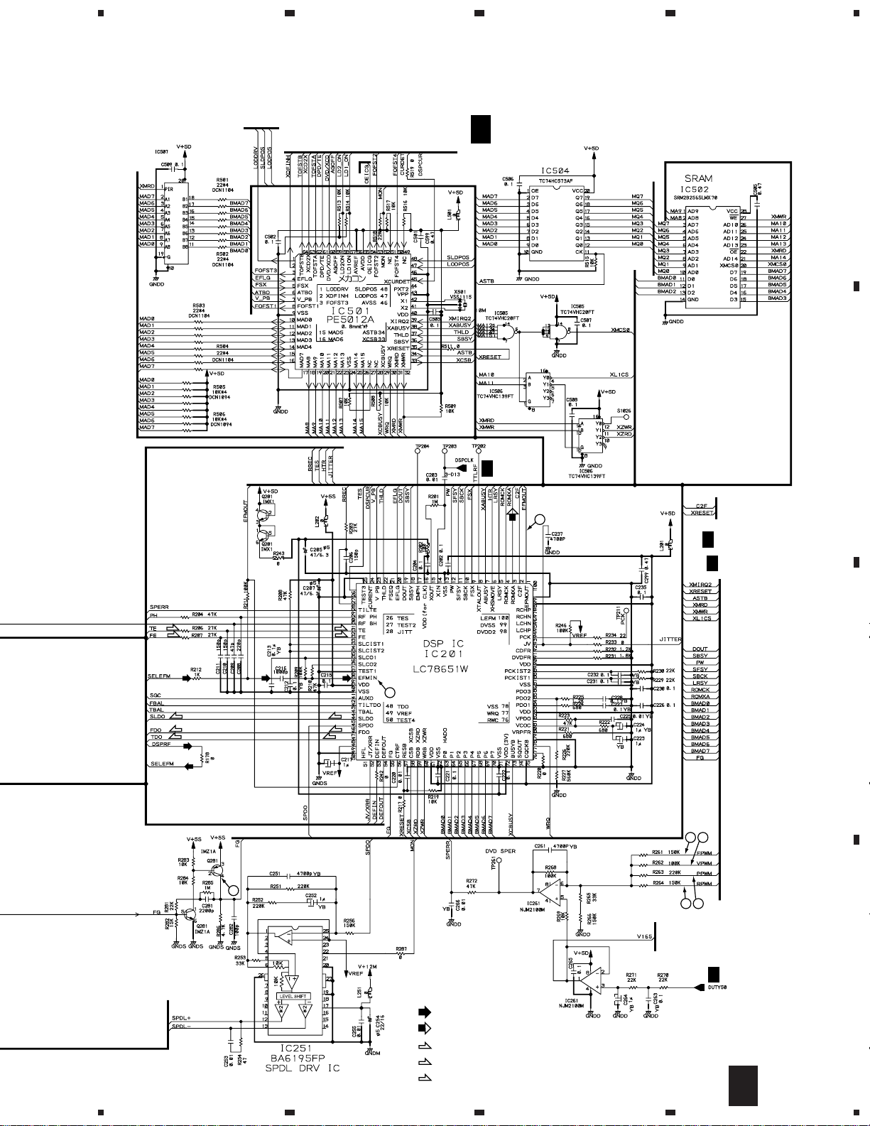
3.2 DVDM ASSY (1/3)
A
23
F
2/3
2/6
3/6
5/6
1/6
6/6
4
(CD)
(T)
1/2
2/2
(DVD)
(F)
4
3
2
(DVD)
ADC1175CIJMX
to CN120
(DVD)
(DVD)
F
2/3
1
4/6
to IC501
(DVD)
(DVD)
B
CN103
F
2/3
(DVD)
(F)
(CD)
(F)
L
(T)
(T)
(T)
(F)
(F)
C
PICKUP ASSY
D
CN9002
B
(T)
(F)
(F)
to
IC501
(F)
(F)
(T)
to IC501
(S)
(F)
(T)
(T)
(F)
(F)
(T)
(T)
(F)
(S)
(S)
(S)
(S)
2/2
1/2
12
1/3
F
1234
Page 13
5
678
DV-K301C
from Q107,Q108
TC74VHCT245AFT
to CN120
to IC101
10MHz
F
1/3
DVDM ASSY(1/3) (VWS1366)
1/2
F
2/3
2/2
1/2
2/2
6
(CD)
to IC601
F
2/3
F
2/3
to IC701
A
B
(T)
(F)
(CD)
(CD)
(S)
(F)
(T)
(CD)
(CD)
7
5
(T)
(F)
(CD)
5
(S)
(F)
(T)
8 9
2/2
to IC302
1/2
: RF SIGNAL ROUTE
: ROM DATA SIGNAL ROUTE
(F)
: FOCUS SERVO LOOP LINE
(T)
: TRACKING SERVO LOOP LINE
(S)
: SLIDER SERVO LOOP LINE
6
7
11 10
F
2/3
F
1/3
13
8
C
D
Page 14
1
DV-K301C
3.3 DVDM ASSY (2/3)
23
4
A
VYW1587
B
F
2/3
DVDM ASSY(2/3) (VWS1366)
: AUDIO SIGNAL ROUTE
: ROM DATA SIGNAL ROUTE
F
3/3
XCSDOLV,XCS6,XWRL,XWRH,XLT3,
XAMUTE,XDACK1,XDREQ1,IR,SEL-IR,
48/44,XDVRST1,XAVIRQ0,NSP-SW,
SSCK,SSO,XRESET
F
3/3
F
3/3
F
C
2/2
D
1/3
F
1/3
A2-A10
14
1/2
2/3
F
1234
20MHz
Page 15
5
678
DV-K301C
A
from IC801
F
3/3
(DVD)
(DVD)
from IC701
F
3/3
F
3/3
(DVD)
F
1/3
from IC301
F
1/3
F
3/3
F
1/3
B
from IC301
F
1/3
C
SERVO
F
1/3
to IC801
F
F
3/3
(CD)
F
3/3
1/3
F
3/3
F
1/3
G
CN101
F
F
1/3
2/3
8
15
to IC801
F
3/3
5
from IC201
F
1/3
6
7
D
Page 16
1
DV-K301C
3.4 DVDM ASSY (3/3)
A
B
23
F
2/3
F
2/3
F
2/3
4
F
2/3
F
2/3
F
2/3
(DVD)
from IC701
F
C
14 17
13 16
(Y)
(C)
12 15
from IC701
F
2/3
D
(V/CB)
2/3
(DVD)
from IC701
F
2/3
16
(V/CB)
(C)
(Y)
(C) (C)
3/3
F
1234
(V/CB)
(Y)(Y)
Page 17

5
678
DV-K301C
CLOCK GEANERATOR SECTION
for IC801
F
F
for IC701
F
1/3
for IC201
2/3
for IC801
2/3
F
F
DVDM ASSY(3/3)
3/3
(VWS1366)
: AUDIO SIGNAL ROUTE
: ROM DATA SIGNAL ROUTE
(V/CB)
: V/CB SIGNAL ROUTE
(Y)
: Y SIGNAL ROUTE
(C)
: C SIGNAL ROUTE
2/3
CN9020
VKN1479
A
B
K
CN901
(V/CB)
(V/CB)
(C)
(Y)
C
F
2/3
(Y)
(C)
K
(C)
(Y)
(V/CB)
CN501
D
3/3
F
5
6
7
8
17
Page 18

1
23
DV-K301C
3.5 FLKY, KYLB, PWSB and MICB ASSEMBLIES
4
A
FLKY ASSY
G
(RL : VWG2011)
(RAM : VWG2010)
CN602
2/3
F
PWSB ASSY
I
B
(RL : VWG2016)
(RAM : VWG2015)
KYLB ASSY
H
(VWG2014)
[LAMP]
RAM TYPE ONLY
RED
MICB ASSY (VWV1637)
J
F9406
C
K
CN401
D
18
G H I J
1234
Page 19

5
678
DV-K301C
KYLB ASSY
S201 - S211 : 1 - +10
FLKY ASSY
S131 : STOP ( )
S132 : PLAY ( )
S133 : PAUSE ( )
S134 : DISC SELECT
PWSB ASSY
S300 : KEY CONTROL ( )
S301 : KEY CONTROL ( )
S302 : POWER (RAM TYPE ONLY)
S135 : DISC SELECT
S136 : OPEN/CLOSE ( )
S137 : DISC CHANGE
S138 : DISC SELECT
ORAGE
S139 : KARAOKE MODE
S150 : ONE-TOUCH KARAOKE
S151 : PLAYBACK CONTROL
S152 : RETURN
S138 : FORWARD ( )
S159 : REVERSE ( )
FL TUBE
A
RL TYPE
ONLY
RAM
TYPE
ONLY
B
PURE GREEN
PURE GREEN
PLAY: GREEN
OTHERS: ORANGE
PLAY: GREEN
OTHERS: ORANGE
PLAY: GREEN
OTHERS: ORANGE
C
D
G
5
6
7
8
19
Page 20

1
DV-K301C
3.6 KRJB ASSY
A
23
(V/CB)
4
(V/CB)
CN9030
3/3
F
B
(C)
(Y) (Y)
(V/CB)
(C)
(V/CB)
(C)
(C)
(Y)
(Y)
CN9020
3/3
F
C
CN402
J
D
20
K
1234
2/3
1/3
3/3
Page 21

5
678
DV-K301C
KRJB ASSY
K
(RL : VWV1625)
(RAM : VWV1654)
A
B
S601 : ATTENUATOR
2/2
1/2
: AUDIO SIGNAL ROUTE
(V/CB)
: V/CB SIGNAL ROUTE
(Y)
: Y SIGNAL ROUTE
(C)
: C SIGNAL ROUTE
C
D
K
5
6
7
8
21
Page 22

1
L
POWER SUUPLY ASSY (VWR1306)
AC POWER
CORD
CN110
1/3
F
MSWB ASSY
(VWG1997)
M
RL TYPE ONLY
POWER
0.01/AC250V
P101
AEK7009
1A
P102
AEK7012
1.6A
P103
AEK7008
800mA
F1
REK1102
2.5A
P301
AEK7008
800mA
NOTE OF SPARE PARTS IN POWER SUPPLY (SYPS) ASSY
• In case of repairing, use the described parts only to prevent an accident.
• Please write the red mark on the board when the primary section of POWER SUPPLY (SYPS) Assy is repaired.
• Please take care to keep the space, not touching other parts when replacing the parts.
• NOTE FOR FUSE REPLACEMENT
FOR CONTINUED PROTECTION AGAINST RISK OF FIRE.
REPLACE WITH SAME TYPE AND RATINGS ONLY.
CAUTION -
CAUTION : FOR CONTINUED PROTECTION AGAINST RISK OF FIRE,
REPLACE ONLY WITH SAME TYPE NO. 491.800 MFD. BY
LITTELFUSE INC. FOR P101, P103, P301 AND NO. 491 01.6
MFD. BY LITTELFUSE INC. FOR P102.
23
DV-K301C
3.7 POWER SUPPLY and MSWB ASSEMBLIES
A
B
4
C
D
22
L
M
1234
Page 23

1
Q109-Emitter (RFI)
V: 100mV/div. H: 0.1µS/div.
7
Q281-Collector (FG)
V: 1V/div. H: 5mS/div.
13
IC801-pin 39 (Y output)
V: 500mV/div. H: 10µS/div.
2
TP (RFO)
V: 500mV/div. H: 0.1µS/div.
8
Foot of R261 (FPWM)
V: 1V/div. H: 10µS/div.
14
IC801-pin 36 (C output)
V: 500mV/div. H: 10µS/div.
3
IC301-pin 19 (RF for A/D converter)
V: 1V/div. H: 0.2µS/div.
9
Foot of R262 (VPWM)
V: 1V/div. H: 10µS/div.
15
IC801-pin 45 (CB output when
selecting color difference output)
V: 500mV/div. H: 10µS/div.
4
TP (Tracking Error)
V: 1V/div. H: 2mS/div.
10
Foot of R263 (PPWM)
V: 1V/div. H: 0.2µS/div.
16
IC801-pin 39 (Y output when
selecting color difference output)
V: 500mV/div. H: 10µS/div.
5
IC201-pin 39 (EFM before slice)
V: 1V/div. H: 1µS/div.
11
Foot of R264 (RPWM)
17
IC801-pin 36 (CR output when
selecting color difference output)
V: 500mV/div. H: 10µS/div.
6
IC201-pin 1 (EFM)
V: 1V/div. H: 0.2µS/div.
12
IC801-pin 45 (Composite video output)
V: 500mV/div. H: 10µS/div.
DC 2V
DC1.4V
GND
GND
GND
GND
GND
• WAVEFORMS OF DVDM ASSY
Note : The encircled numbers denote measuring point in the schematic diagram.
Measurement condition : No. 1 to 4 and 6 to 11 : Disc MJK1, Title 1-chp 1
No. 5 : CD, ABEX-784 Track 1
No. 12 to 14 : MJK1, Title 1-chp 4
No. 15 to 17 : MJK1, Title 1-chp 5
DV-K301C
23
Page 24

1
23
DV-K301C
4. PCB CONNECTION DIAGRAM
A
NOTE FOR PCB DIAGRAMS :
1. Part numbers in PCB diagrams match those in the schematic
diagrams.
2. A comparison between the main parts of PCB and schematic
diagrams is shown below.
Symbol In PCB
Diagrams
BCE
BCE
D
Symbol In Schematic
Diagrams
BCEBCE
BCE
DGGSS
BCE
DGS
Part Name
Transistor
Transistor
with resistor
Field effect
transistor
4
3. The parts mounted on this PCB include all necessary parts for
several destinations.
For further information for respective destinations, be sure to
check with the schematic diagram.
4. View point of PCB diagrams.
Connector
Capacitor
SIDE A
P.C.Board
Chip Part
SIDE B
B
Resistor array
3-terminal
regulator
4.1 SW, TRADE, MOTOR, SMEB and FGSB ASSEMBLIES
MOTOR ASSY
C
LOADING
MOTOR
TRADE ASSY
B
C
F
A
CN103
(VNP1669-A)
M
SW ASSY
(VNP1669-A)
SMEB
D
ASSY
M
M
D
CARRIAGE
MOTOR
SPINDLE
MOTOR
(VNP1654-A)
PC101
R101
(VNP1669-A)
FGSB ASSY
E
(VNP1661-B)
SIDE A
24
A B C D E
1234
Page 25

(VNP1677-B)
CN110
F
POWER SUPPLY ASSY
L
MSWB ASSY
M
AC IN
RL TYPE ONLY
IC102
IC103
VR201
IC201
Q1
IC51
Q71
SIDE A
1
234
4.2 POWER SUPPLY and MSWB ASSEMBLIES
DV-K301C
A
B
C
D
ML
1
2
3
4
25
Page 26

1
DV-K301C
4.3 DVDM ASSY
23
4
A
DVDM ASSY
F
B
• This PCB is a four-layered board. Middle layer is mainly connected to Vcc and GND.
K
CN501
CN901
K
VC901
VR801
IC881
Q881
IC904
Q914
IC801
IC602
IC803
Q604
Q603
IC804 Q801
Q802 IC603
C
D
PICKUP
ASSY
B
CN9002
(VNP1684-A)
VC301
Q109
IC702 IC604
Q111
IC203
Q108
Q106
Q107 Q105 IC703
IC101
Q113
Q103
IC352
Q402 Q403
IC251
Q662
Q661
IC301
IC261
IC302
IC303
IC401
Q401
IC507
IC501
26
CN103
L
G
CN101
SIDE A
F
1234
Page 27

1
234
DV-K301C
A
• This PCB is a four-layered board. Middle layer is mainly connected to Vcc and GND.
DVDM ASSY
F
Q601 Q602 IC906
Q872
Q862 Q852
IC901
IC605
Q871 Q861 Q851
IC601 IC806
IC805 Q803
IC701
Q114
Q301
IC903
IC810 IC807
IC809 IC808
IC802
Q201
IC201
Q112
B
C
Q101
Q102
IC506
IC504
IC502
(VNP1684-A)
IC505
IC371
Q281
Q251
D
SIDE B
F
1
2
3
4
27
Page 28

1
23
DV-K301C
4.4 FLKY, KYLB, PWSB and MICB ASSEMBLIES
4
A
PWSB ASSY
I
B
MICB ASSY
J
Q101
C
KYLB ASSY
H
D
SIDE A
28
G H I J
1234
Page 29

5
678
DV-K301C
A
IC401
IC402
K
CN401
FLKY ASSY
G
B
F
CN602
C
IC102
D
SIDE A
5
6
7
(VNP1673-A)
G H J
29
8
Page 30

1
DV-K301C
23
4
A
FLKY ASSY
G
B
MICB ASSY
J
C
Q104
Q177
KYLB ASSY
H
D
Q103 Q102
Q171 Q175
Q170 Q172
Q174 Q178
SIDE B
30
G H J
1234
Page 31

5
678
DV-K301C
PWSB ASSY
I
A
B
5
IC101
C
D
SIDE B
6
7
(VNP1673-A)
G H I J
8
31
Page 32

1
DV-K301C
4.5 KRJB ASSY
23
4
A
B
KRJB ASSY
K
CN402
J
IC199 IC299 IC999
SIDE A
IC801
IC800
C
D
IC901
IC501 IC402
32
KRJB ASSY
K
SIDE B
K
1234
Page 33

5
678
DV-K301C
A
B
CN9030
F
IC599
IC402 IC401 IC304 IC301
SIDE A
CN9020
F
IC101Q222
Q221 Q121-Q123
(VNP1677-B)
Q111-Q116
C
D
SIDE B
K
5
6
7
8
33
Page 34

DV-K301C
Mark No. Description Part No.
Mark No. Description Part No.
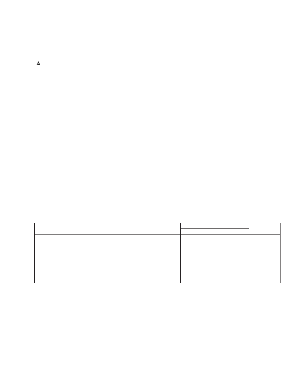
5. PCB PARTS LIST
NOTES:•Parts marked by "NSP" are generally unavailable because they are not in our Master Spare Parts List.
The mark found on some component parts indicates the importance of the safety factor of the part.
•
Therefore, when replacing, be sure to use parts of identical designation.
When ordering resistors, first convert resistance values into code form as shown in the following examples.
•
Ex.1 When there are 2 effective digits (any digit apart from 0), such as 560 ohm and 47k ohm (tolerance is shown by J=5%,
and K=10%).
560 Ω→56 × 10
47k Ω→47 × 103→ 473 ........................................................RD1/4PU 4 7 3 J
0.5 Ω→R50 .....................................................................................RN2H
1 Ω→1R0 ..................................................................................... RS1P
Ex.2 When there are 3 effective digits (such as in high precision metal film resistors).
5.62k Ω→ 562 × 10
LIST OF WHOLE PCB ASSEMBLIES
Mark Symbol and Description
NSP $M MECH DVD ASSY VWT1154 VWT1154
NSP MECH ASSY VWM1878 VWM1878
NSP SW ASSY VWG2002 VWG2002
NSP TRADE ASSY VWG2003 VWG2003
NSP MOTOR ASSY VWG2004 VWG2004
NSP SERVO MECH ASSY VWT1156 VWT1156
NSP SMEB ASSY VWG1968 VWG1968
NSP FGSB ASSY VWG2009 VWG2009
1
→ 561 ........................................................RD1/4PU 5 6 1 J
R 5 0
1 R 0
1
→ 5621 ......................................................RN1/4PC 5 6 2 1 F
Part No.
DV-K301C/RL DV-K301C/RAM
K
K
Remarks
DVDM ASSY VWS1366 VWS1366
NSP FRPB ASSY VWM1883 VWM1882
FLKY ASSY VWG2011 VWG2010
NSP KYLB ASSY VWG2014 VWG2014
NSP PWSB ASSY VWG2016 VWG2015
MICB ASSY VWV1637 VWV1637
KRJB ASSY Not used VWV1654
NSP KRSB ASSY VWM1873 Not used
KRJB ASSY VWV1625 Not used
NSP MSWB ASSY VWG1997 Not used
POWER SUPPLY ASSY VWR1306 VWR1306
Mark No. Description Part No.
SW ASSY
A
SWITCHES
S9502 ASG7009
S9501 DSG1017
Mark No. Description Part No.
MOTOR ASSY
C
SWITCH
S9503 ASG7009
OTHERS
OTHERS
J9501 JUMPER WIRE 6P D20PWY0610E
J9502 JUMPER WIRE 4P D20PWW0405E
TRADE ASSY
B
OTHERS
CN9501 6P JUMPER CONNECTOR 52147-0610
CN9002 FFC CONNECTOR 13P SLW13R-1C7
CN9001 FFC CONNECTOR 8P SLW8R-1C7
34
SMEB ASSY
D
SWITCH
S201 DSG1016
OTHERS
CN201 3P FFC CONNECTOR 52044-0345
CN202 8P FFC CONNECTOR VKN1212
PC BOARD SMEB VNP1654
Page 35

DV-K301C
Mark No. Description Part No.
FGSB ASSY
E
SEMICONDUCTOR
PC101 TLP910(O)
RESISTORS
All Resistors RS1/10S J
DVDM ASSY
F
SEMICONDUCTORS
IC301 ADC1175CIJMX
IC401 BA178M08FP
Q401 2SB1260
IC371 BA10393F
IC352 BA5982FP
IC251 BA6195FP
IC901 CY2081SL-638
IC702 HM514800CJ-7
IC101 LA9701M
IC201 LC78651W
IC802
IC801 MB86371C
IC261,IC302 NJM2100M
IC601 PD3381A
IC701 PD4833A
IC501 PE5012A
IC502 SRM2B256SLMX70
IC881 TA75S01F
IC604 TC551001BFL-85
IC504 TC74HC573AF
IC303 TC74HCU04AF
IC807,IC808 TC74LCX245FT
IC810 TC74VHC00FT
IC506,IC605 TC74VHC139FT
IC505 TC74VHC20FT
IC805,IC806,IC809 TC74VHC541FT
IC507 TC74VHCT245AFT
IC703 TC74VHCT541AFT
IC903,IC904,IC906 TC7WU04F
IC603 VYW1587
Q603 DTA114EK
Q107,Q111,Q602 DTC114EK
Q601,Q661,Q662,Q803 DTC114TK
Q108 HN1K03FU
Q102,Q106,Q109,Q851,Q852 IMT1A
Q861,Q862,Q871,Q872 IMT1A
Q101,Q105,Q112-Q114,Q201 IMX1
Q402,Q881 IMX1
Q103,Q281,Q301 IMZ1A
D301 KV1410
D371,D372 MA152WK
D601 RB501V-40
MB811171622A-100FN
COILS AND FILTERS
F6630,F6640,F6710 CHIP BEAD DTF1067
F4010,F4020,F4030,F4040,F4050 DTF1070
F4060,F8010 CHIP BEAD DTF1070
F801 VIDEO FILTER VTF1098
L304 CHIP COIL(1.5µH) VTL1059
CHIP BEAD
Mark No. Description Part No.
L101,L303 CHIP COIL(10µH) VTL1061
L804 CHIP COIL VTL1067
L6740,L6750,L6760,L6770,L6780 VTL1075
CHIP BEAD
L6790,L6800,L6810,L6820,L9050 VTL1075
CHIP BEAD
L9560,L9570,L9580,L9620,L9630 VTL1075
CHIP BEAD
L9640,L9870,L9880,L9890 VTL1075
CHIP BEAD
CAPACITORS
C605 CCSRCH100D50
C123,C282,C610,C611,C716 CCSRCH101J50
C903 CCSRCH101J50
C206,C210,C211,C240 CCSRCH151J50
C126,C307,C905 CCSRCH180J50
C116,C151 CCSRCH220J50
C152,C208 CCSRCH221J50
C135 CCSRCH270J50
C322 CCSRCH330J50
C352,C360 CCSRCH331J50
C104-C108,C124,C134,C209 CCSRCH470J50
C314,C324 CCSRCH470J50
C117,C122 CCSRCH471J50
C128,C309 CCSRCH560J50
C127,C308 CCSRCH5R0C50
C145,C146 CCSRCH820J50
C129,C142,C414,C832 CEV101M10
C113,C139,C254,C358,C409 CEV220M16
C411 CEV220M16
C801,C802,C811,C814,C836 CEV221M4
C111,C147,C149,C205,C207 CEV470M6R3
C301,C304,C368,C401,C403 CEV470M6R3
C405,C407,C807,C812,C815 CEV470M6R3
C881 CEV470M6R3
C140,C223,C224,C252,C264 CKSQYB105K10
C312,C803,C804,C813,C817 CKSQYB105K10
C819,C821,C823,C826 CKSQYB105K10
C829-C831,C833 CKSQYB105K10
C217,C302,C305,C417 CKSQYF105Z16
C216,C313,C323 CKSRYB102K50
C133,C136,C203,C220,C225 CKSRYB103K50
C253,C255,C266,C320,C321 CKSRYB103K50
C616,C662,C703,C711 CKSRYB103K50
C101,C102,C114,C118,C121 CKSRYB104K16
C130,C138,C153,C204 CKSRYB104K16
C212,C213,C227,C228 CKSRYB104K16
C231,C232,C263,C311 CKSRYB104K16
C315-C317,C362-C365,C413 CKSRYB104K16
C805,C806,C808,C810 CKSRYB104K16
C281 CKSRYB222K50
C137,C354,C357 CKSRYB223K25
C237,C239,C251,C261 CKSRYB472K50
C109,C110,C120,C131,C143 CKSRYF104Z16
C148,C150,C202,C215 CKSRYF104Z16
C221,C222,C226,C230,C235 CKSRYF104Z16
C265,C303,C306,C319,C359 CKSRYF104Z16
C366,C367,C369-C372,C402 CKSRYF104Z16
C404,C406,C408,C410,C412 CKSRYF104Z16
C415,C502,C503,C506-C509 CKSRYF104Z16
C603,C604,C606-C609,C612 CKSRYF104Z16
C615,C617-C620,C661,C691 CKSRYF104Z16
35
Page 36

DV-K301C
Mark No. Description Part No.
C702,C704-C710,C712-C715 CKSRYF104Z16
C717-C719,C725,C818,C820 CKSRYF104Z16
C822,C824,C825,C827,C828 CKSRYF104Z16
C834,C838,C840,C842,C843 CKSRYF104Z16
C845,C847,C851,C854,C861 CKSRYF104Z16
C864,C871,C874,C882,C883 CKSRYF104Z16
C907,C910,C915 CKSRYF104Z16
C816,C837,C844,C848 (2.2µF/6.3V) VCG1030
C299,C328,C505,C599,C602 VCG1032
(0.47µF)
C722,C723,C799,C902 (0.47µF) VCG1032
VC301 (40pF) VCM1010
VC901 (30pF) VCM1011
RESISTORS
R123 (39Ω) ACN7047
R607-R611,R723 (47Ω) DCN1090
R505,R506,R615,R616,R620 (10kΩ) DCN1094
R692,R708,R709,R733,R734 (10kΩ) DCN1094
R740,R741,R748,R749 (10kΩ) DCN1094
R121,R501-R504,R603-R606 (22Ω) DCN1104
R691,R712,R713,R715,R716 (22Ω) DCN1104
R731,R732,R816,R818,R819 (22Ω) DCN1104
R833-R835 (22Ω) DCN1104
R1020,R162,R173,R2010,R2020 RS1/10S0R0J
R243,R2510,R301,R3010,R302 RS1/10S0R0J
R3020,R3050,R3510,R3520 RS1/10S0R0J
R405-R407,R5010,R5020,R6010 RS1/10S0R0J
R6030,R6040,R672,R673,R7010 RS1/10S0R0J
R7020,R8020,R8030,R839,R9010 RS1/10S0R0J
R9020,R9030,R9040,R9510,R9520 RS1/10S0R0J
R982,R983 RS1/10S0R0J
R202 RS1/10S101J
R886 RS1/16S1001F
R306,R334,R807-R809 RS1/16S1500F
R829,R884,R885 RS1/16S2000F
R804,R840 RS1/16S2201F
R801,R803,R838 RS1/16S2701F
R164,R853,R863,R873 RS1/16S5600F
Other Resistors RS1/16S J
OTHERS
FLEXIBLE CABLE 7P VDA1681
CN106 7P FFC CONNECTOR VKN1299
CN201 B TO B CONNECTOR 14P VKN1324
CN602 14P FFC CONNECTOR VKN1418
CN120 24P FFC CONNECTOR VKN1464
Mark No. Description Part No.
FLKY ASSY
G
(1) CONTRAST TABLE
VWG2011 and VWG2010 are constructed the same except
for the following :
Mark Symbol and Description
R161 RS1/10S0R0J Not used
R162 Not used RS1/10S0R0J
Part No.
VWG2011 VWG2010
Remarks
(2) PARTS LIST FOR VWG2011
SEMICONDUCTORS
IC101 PE5020A
IC102 S-806D
Q101 DTD113ES
Q102-Q104,Q172,Q175,Q178 PDTA114EK
Q170,Q171,Q174,Q177 PDTC114EK
D102 EP05Q04
D115,D116 SLP6118C51H
D111-D114 SLP7118C51H
D171,D174,D177 VRPG5615S
SWITCHES
S131-S139,S150-S152 RSG1030
S158,S159 RSG1030
CAPACITORS
C105 CEJA101M10
C120-C122,C127,C130,C140 CKSQYB102K50
C119,C125,C126 CKSQYB103K50
C103,C104,C106-C110,C114 CKSQYF104Z50
C123 CKSQYF104Z50
RESISTORS
R121-R123 RN1/10SE1001D
Other Resistors RS1/10S J
OTHERS
CN103 6P FFC CONNECTOR 52045-0645
CN104 CONNECTOR 52084-0910
V101 FL TUBE VAW1046
CN101 14P FFC CONNECTOR VKN1274
X101 CERAMIC RESONATOR VSS1104
REMOTE RECEIVER UNIT GP1U28X
SPACER VEC1599
FL HOLDER VNF1087
(5MHz)
36
CN103 13P FFC CONNECTOR VKN1472
CN9030 14P FFC CONNECTOR VKN1473
CN110,CN9020 VKN1479
26P FFC CONNECTOR
CN180 B TO B CONNECTOR 8P VKN1485
BAR CODE LABEL VRW1750
X601 CHIP CERAMIC RESONATOR VSS1114
(20MHz)
X501 CHIP CERAMIC RESONATOR VSS1115
(10MHz)
X901 CRYSTAL (13.824MHz) VSS1129
KYLB ASSY
H
SEMICONDUCTOR
D201 MA111
SWITCHES
S201-S211 RSG1030
CAPACITOR
C201 CKSQYF225Z16
RESISTORS
All Resistors RS1/10S J
Page 37

DV-K301C
Mark No. Description Part No.
OTHERS
CN201 FJ CONNECTOR 4P 04R-FJ
PL201 LAMP (DVD ILLUMI.) VEL1022
PWSB ASSY
I
(1) CONTRAST TABLE
VWG2016 and VWG2015 are constructed the same except
for the following :
Mark Symbol and Description
S302 Not used RSG1030
R302 Not used RS1/10S111J
Part No.
VWG2016 VWG2015
Remarks
(2) PARTS LIST FOR VWG2016
SEMICONDUCTORS
Q301 PDTC114EK
D301 SLP9118C51H
SWITCHES
S300,S301 RSG1030
CAPACITOR
C302 CKSQYF104Z50
RESISTORS
All Resistors RS1/10S J
OTHERS
CN302 FJ CONNECTOR 4P 04P-FJ
CN301 FFC CONNECTOR 6P 52492-0620
MICB ASSY
J
SEMICONDUCTORS
IC402 BA4560F
IC401 NJM2068M
FILTER
F9406 CHIP SOLID INDUCTOR VTF1096
CAPACITORS
C424 CCSQSL271J50
C401,C402 CEAT101M10
C403,C404,C412,C420,C421 CKSQYB103K50
C426 CKSQYB103K50
C405,C408 CKSQYB122K50
C406,C409 CKSQYB152K50
C425 CKSQYB224K16
C431,C432 CKSQYF225Z16
Mark No. Description Part No.
OTHERS
CN402 10P FFC CONNECTOR 52045-1045
CN401 CONNECTOR 53095-0910
JA403 HEADPHONE JACK RKN1006
JA401,JA402 MIC. JACK VKN1147
KRJB ASSY
K
PCB BINDER DEF1012
SNAP PLATE VNE1102
JACK HOLDER VNE2161
(1) CONTRAST TABLE
VWV1625 and VWV1654 are constructed the same except
for the following :
Mark Symbol and Description
PC Board KRSB Not used VNP1677
Part No.
VWV1625 VWV1654
Remarks
(2) PARTS LIST FOR VWV1625
SEMICONDUCTORS
IC101 BA4560F
IC999 IR3M03A
IC501 LA7135M
IC199 NJM78L08A
IC299 NJM79L08A
IC301 PE8001A
IC402 TC74HC157AF
IC801,IC901 TC74HCT7007AF
IC304 TC7WU04F
IC401 TC9409BF-001
Q112 2PB709A
Q902 2PD601A
Q901 2SB1260
Q111,Q121,Q221,Q222 2SD2114K
Q122 PDTA124EK
Q113,Q116,Q123 PDTC124EK
D199,D992 EC10QS04
D601 MA111
COILS AND FILTERS
L992 LFA271J
L999 LFA470J
L802 PULSE TRANS. PTL1003
F301,F304,F308,F309,F701 VTF1096
CHIP SOLID INDUCTOR
F801 CHIP SOLID INDUCTOR VTF1096
SWITCHES
S101 VSH1009
S601 VSH1020
RESISTORS
VR401-VR403 (10kΩ) VCS1040
Other Resistors RS1/10S J
CAPACITORS
C412 CCSQCH220J50
C107,C207 CCSQCH331J50
C305 CCSQCH4R0C50
C102,C202 CCSQCH561J50
C103,C203 CCSQCH910J50
37
Page 38

DV-K301C
Mark No. Description Part No.
C410,C434,C440,C442 CEAT101M10
C470,C471,C502,C580,C590 CEAT101M10
C701,C801,C803,C902 CEAT101M10
C901,C966,C994 CEAT101M16
C513,C521 CEAT102M6R3
C351,C380,C390 CEAT221M6R3
C101,C105,C106,C201 CEAT470M10
C205,C206,C311,C318 CEAT470M10
C104,C204,C301,C308,C309 CKSQYB103K50
C315,C320,C322,C340,C404 CKSQYB103K50
C407,C421,C435,C804,C905 CKSQYB103K50
C444,C503,C506,C510 CKSQYB104K25
C403 CKSQYB122K50
C993 CKSQYB471K50
C422 CKSQYB562K50
C108,C199,C208,C402,C415 CKSQYF104Z25
C417,C420,C424,C443,C509 CKSQYF104Z25
C517,C520,C602,C702,C802 CKSQYF104Z25
C806,C900 CKSQYF104Z25
C299,C999 CKSQYF225Z16
RESISTORS
R518,R523 RN1/10SC62R0D
R515 RN1/10SC68R0D
R104,R204 RN1/10SE1102D
R995 RN1/10SE1801D
R999 RN1/10SE2200D
Mark No. Description Part No.
MSWB ASSY
M
SWITCH
S10 ASG1006
CAPACITOR
C10 (0.01µF/AC250V) ACG7010
OTHERS
CN10 AMP U-P CONNECTOR 2P 2-178496-4
R101,R201 RN1/10SE5601D
Other Resistors RS1/10S J
OTHERS
CN401 10P FFC CONNECTOR 52045-1045
CN502 4P MINI DIN SOCKET AKP7008
JA701 OPTICAL LINK OUT GP1F32T
JA601 REMOTE CONTROL JACK RKN1004
JA501 1P PIN JACK VKB1063
JA101 4P PIN JACK VKB1065
JA801 1P PIN JACK (NI, BLK) VKB1077
CN501 14P FFC CONNECTOR VKN1245
CN901 26P FFC CONNECTOR VKN1257
KN101,KN501,KN801,KN901 VNF1084
POWER SUPPLY ASSY
L
PCB BINDER VEF1040
SCREW TERMINAL VNE1948
EARTH METAL FITTING
OTHERS
F1 FUSE (2.5A) REK1102
P101 PROTECTOR (1A) AEK7009
P103,P301 PROTECTOR AEK7008
P102 PROTECTOR (1.6A) AEK7012
(800mA)
38
Page 39

6. ADJUSTMENT
6.1 ADJUSTMENT ITEMS AND LOCATION
DV-K301C
Adjustment Points (PCB Part)
DVDM ASSY
CN9020CN9030
1
1
IC801
MB86371C
VC901
CN201
1, 2 : Focus Error
3, 4 : GND
5, 6 : RF
7 : S REQ
8 : 3.3V
9,10 : Tracking Error
11,12 : VREF (Approx. 2.5V)
13 : VCO DR
14 : Focus Drive(DSP output)
14
13
1
CN201
CN110
2
IC302
2
VC301
IC904
5
CN120
CN103
SIDE A
1
Adjustment Items
[Electrical Part]
16MHz Master Clock Adjustment
1
2
VCO Offset Adjustment
6.2 JIGS AND MEASURING INSTRUMENTS
CH1 CH2
(X) (Y)
Dual-trace oscilloscope
(with delay)
Frequency band ≥ 40MHz
1
Frequency counter
Display digit ≥ 8-digit
6.3 NECESSARY ADJUSTMENT POINTS
When
EXCHANGE PCB ASSY
Exchange board
KRJB ASSY
Exchange board
DVDM ASSY
Mechanical
point
Electric
point
Mechanical
point
Electric
point
Note : and are adjusted already.
Screwdriver (small)
Adjustment Points
39
Page 40

DV-K301C
6.4 ELECTRICAL ADJUSTMENT
1
16MHz Master Clock Adjustment
• Normal mode
• Power ON
START
DVDM ASSY
5
IC904
2
VCO Offset Adjustment
DVDM ASSY
16.934400MHz ± 80Hz
VC901
Player
Frequency counter
40
• Normal mode
• Play the DVD test disc
START
DVDM ASSY
1
IC302
Player
VC301
DVDM ASSY
Probe (10:1)
CH1 CH2
(X) (Y)
1.9V± 0.1V
GND
Oscilloscope
V: 50mV/div.
H: 10msec/div.
DC mode
TV trigger
Page 41

DV-K301C
7. GENERAL INFORMATION
7.1 IC
• The information shown in the list is basic information and may not correspond exactly to that shown in the schematic diagrams.
• For LA9701M (DVDM Assy : IC101) and LC78651W (DVDM Assy : IC201), refer to the service guide RRV2004.
PE5020A (FLKY ASSY : IC101)
• FL Control IC
Pin Function
•
.oNkraMemaNniPO/InoitcnuF.oNkraMemaNniPO/InoitcnuF
149P7G
239P6G2413P)CN(
329P5G3403P)CN(
419P4G4430P)CN(
509P3G5420PURHTPSDO eurhT:HtuptuoedomeurhtPSD
618P2G6410PSCPSDO PSDottuptuotcelespihC
708P1G7400PRILESI tupnilangislortnocetomeR
DD
V
8V
972P0KCSO
0162P0OSO
1152P)CN(O noitcennocnoN1507P)CN(
2142PTLI
3132PYDAERXO
4122P1KCSO/I
5112P1OSO/I
6102P1ISI
71
8147P
9137P
02VA
1271P2SMI tupninoitanimircsidnoitanitseD16711P51P
2261P
3251P0NIK
4241P2NIK46411P21P
5231P1NIK56311P11P
6221PTNOCCIMI tupnilortnocenohporhciM66211P01P
7211PLOVOHCEI tupniemulovohcelatigiD76111P9P
8201P0SMI tupninoitanimircsidnoitanitseD86011P8P
92VA
03VA
1340P40PIdesutoN17V
232TX)CN(
33V
431X1XI
532X2X
6373PDELCBPO
7363PDEL1CSIDO NO:LtuptuoDEL1csiD77001P11G
8353PDEL2CSIDO NO:LtuptuoDEL2csiD8779P01G
9343PDEL3CSIDO NO:LtuptuoDEL3csiD9769P9G
0433P
CC
TESER
DEL
DEL
SS
V
SS
DD
VA
DD
FER
VA
FER
SS
V
SS
ONO:HtuptuognimitLF
−
NITESERI teseR:LtupniteseR75321P)CN(O noitcennocnoN
EKOARAK
ONO:LtuptuoDELekoaraK85221P221P
hcuoT-enO
O
−
TUOTESER
OteseR:LtupnitesermetsyS26611P41P
−
−
−
−
−
NOREWOP
ONO:HFFO/NOV5WS0859P8G
NO:L
DNG06021P
ItupnIyeK
DNG37401P4P
NO:L
nipylppusrewoP84CICI
htiwtuptuokcolcnoitacinummoC
rellortnocmetsys
htiwtuptuoatadnoitacinummoC
rellortnocmetsys
rellortnocmetsys
noissimrepnoitacinummoC:H
rellortnocmetsys
noissimrepnoitacinummoC:L
htiwtuptuokcolcnoitacinummoC
rellortnocmetsys
htiwtuptuoatadnoitacinummoC
rellortnocmetsys
htiwtupniatadnoitacinummoC
rellortnocmetsys
tuptuoDELekoaraKhcuotenO
nipylppusrewoP96701P7P
nipylppusrewopecnerefeR07601P6P
noitcennocnoN27501P5P
kcolcrossecorporcimatcennoC
tuptuoDELlortnockcabyalP
1423P)CN(
9427P)CN(
0517P)CN(
htiwenilekahsdnahnoitacinummoC
htiwenilekahsdnahnoitacinummoC
DD
V
25V
35721PNOCIMO enohporhcimFFO/NOehthctiwS
45621P
55521PLESMEOI
65421PPMALO NO:HFFO/NOpmalDVD
95121P121P
36511P31P
47301P3P
57201P2P
67101P1P
DD
DELYBNTS
REWOPNO
DAOL
V72–
OdesutoN
−
OnoitcennocnoN
−
OtuptuoDELybdnatS
InoitcennocnoN
I
ONO:HtuptuotnemgesLF
−
ONO:HtuptuotnemgesLF
noitcennocnoN
nipylppusrewoP
MEO/reenoiPehthctiwS
MEO:H,REENOIP:L
V72–roftupnI
LFtaNOREWOP/YBTSehthctiwS
YBTS:Lpudesirsirellortnoc
41
Page 42

DV-K301C
7.2 DISASSEMBLY
BONNET
Bonnet
1
×2
DVDM ASSY
1
Check FL display → [No Disc]
2
POWER OFF
3
2
1
×2
1
×2
DVDM Assy
5
Flexible Cable
6
×3
4
Remove FFC Guard
FFC Guard
-1
4
FFC Guard
7
-2
4
Unhook
DVDM Assy
-3
4
DVDM Assy
DVDM Assy
Unhook
DVDM Assy
8
Slit
42
Page 43

KRJB ASSY FRONT PANEL SECTION
Note: The loading tray can be pulled out
when the main cam is in this position.
(The Lock Lever should be in the
notch of the Main Cam.)
1
1 1
Rear Panel
Nyron Rivet
4
1
1
×2
DV-K301C
Main Cam
1
Fitting
Lock Lever
Cutting Pliers
3
Release two Binders.
6
2
×4
2
5
4
KRJB Assy
3
×3
Unhook
5
Remove PW Joint and Power Button
(RL type only)
Tray Panel
Rear Panel
KRJB Assy
-3
5
-2
5
Power Button
PW Joint
5
-1
Check that Power Switch is OFF.
43
Page 44

DV-K301C
9
CN602
8
Remove Flexible Cable
(MICB CN402 ↔ KRJB CN401)
$M MECH DVD ASSY
1
Remove Tray Panel.
(Refer to steps to of FRONT PANEL SECTION.)
2
Remove FFC Guard.
(Refer to step of DVDM ASSY.)
144
4
×2
10
DVDM Assy
12
7
Unhook FFC Binder
FLKY Assy
KYLB Assy Front Panel
KRJB Assy
11
10
MICB
Assy
6
×2
MICB Assy
POWER
SUPPLY
Assy
3
Rear
$M MECH
DVD ASSY
5
4
×2
PICKUP Assy
Front
Flexible Cable
8
(Step )
Caution :
• An analog audio output is not outputted when servcing the
player in this condition. Only digital output is outputted.
• There is no problem in the normal movement of the mechanism
and the video output.
Key input can be done.
ON OFF
Caution :
When assembling the $M MECH DVD Assy, connect two
Flexible Cables to CN120 and CN103 on the DVDM Assy first.
Then turn this switch to ON (Front side).
6
×2
CN103 CN120
DVDM ASSY
(at Disassembling)
$M MECH
DVD ASSY
7
44
Page 45

$M MECH DVD ASSY ADDITIONAL TO JOB
Mech Base (Bottom View) Clamper Holder
1
Unhook
×3
2
Unhook
Front
×3
1
CN9001
DV-K301C
Front
TRADE Assy
Front
2
Unhook
×2
3
4
5
Clamper Holder
3
Mech Base
6
4
Rotary Tray
Loading Tray
45
Page 46

DV-K301C
Servo Base Servo Mech Assy-S
1
1
Unhook
1
Unhook
3
Flexible Cable
Unhook
2
Servo Base
Servo Mech Assy-S
2
FFC Holder
Float Rubber
6
(Black)(Hard)
Flexible Cable
Servo Mech Assy-S
4
Unhook
7
Float Rubber
(Black)(Soft)
5
Unhook
×2
×1
46
Servo Base
Page 47

Style the Flexible Cable and Float Rubber Position in the Servo Mech Assy-S
Float Rubber
(Black)(Soft)
DV-K301C
Mark
Servo Mech
Assy-S
Float Rubber
(Black)(Hard)
Flexible Cable
Spindle Motor
Style the Flexible Cable in the $M MECH DVD Assy and Preparation before Installing the Mech Base
Connect a Flexible Cable
Pull out Flexible Cable from this hole.
Pass two Flexible Cables through this hole
before assembling the Mech Base and Loading Tray.
×4
Hook
Caution :
Confirm that the part which a Flexible Cable touches this wall.
47
Page 48

DV-K301C
Spindle
Motor
TA
FA
Slider
IC101
RF IC
IC352
BA5982FP
IC251
BA6195FP
RF
RF
LA9701M
VCO
A/D
CONV.
Sync
Demod
Spindle
control
ECC &
ID Reg.
Sub-CPU
I/F
DRAM I/F
(bus arbitor)
CPU
I/F
DMA
CD-ROM Sync gen.
Sub-code Buffer
VBR Buffer
4M bit DRAM
SREO
Program Stream
XSACK
27
16
PCM DATA,
DOUT
27M
16/36M
PCM DATA
CONT
Loading
Motor
Mechanism
sense SW
System CPU
(32 bit RISC)
ROM
RAM
SREO
XSACK
PCM DATA
OPTICAL
OUT
SR IN
AC-3/PCM D-OUT
COAXIAL
OUT
LSI-11
From
DVDM
ASSY
NTSC PAL
AUTO SELECT
CPU
I/F
S VIDEO
OUT
MIC 1
MIC 2
COMPOSITE
VIDEO
OUT
DVD/V-CD
AV Decoder
DVDM ASSY
FLKY ASSY
KRJB
ASSY
LPF
PWM
FG
FG
IC352 (4/4)
16
TE
FG
TRKG DRV
FOCS DRV
SLD DRV
SPDL DRV
FE
FL CONTROL
UCOM
CLOCK
GEN.
JA701
GP1F32T
L802
PTL1003
IC501
VIDEO AMP & DRIVER
LA7135M
SYSTEM
Decoder
(DMUX)
AV Sync
controller
MPEG2
Video
Decoder
Sub-
picture
Decoder
GUI
Memory Controller
16M bit SDRAM
CODE Buffer
(Video, Audio, Sub-picture,GUI)
MIX
AC3/MPEG1
Audio Decoder
Copy
Guard
NTSC
/PAL
encode
DAC
DAC
DAC
S/PDIF
LSI-11
IC802
MB811171622A-100FN
IC604
TC551001BFL-85
IC603
VYW1587
IC601
PD3381A
IC701
PD4833A
IC301
ADC1175CIJMX
IC201
SERVO DSP
LC78651W
IC501
MECHANISM
CONTROL
PE5012A
IC702
HM514800CJ-7
IC101
PE5020A
IC901
CY2081SL-638
IC801
MB86371C
(MPEG2 Decoder)
L-OUT
R-OUT
IC301
AUDIO DAC
PE8001A
IC401
KARAOKE DSP
TC9409BF-001
IC402
TC74HC157AF
IC501
BA4560F
SEL
AMP
MUTE
AMP
MICB
ASSY
7.3 BLOCK DIAGRAM
48
Page 49

8. PANEL FACILITIES AND SPECIFICATIONS
8.1 PANEL FACILITIES
7 Front panel
¶ Illustration shows the Flat blade 2-pin AC plug model.
Key control buttons
Disc illumination
Turned off when a
Power Switch
Round blade 2-pin
AC plug model
Disc T ab le
Number buttons
disc other than a
DVD is played back.
DV-K301C
RETURN button
PLAYBACK CONTROL
button and indicator
ONE-TOUCH KARAOKE
button and indicator
KARAOKE MODE
button and indicator
DISC CHANGE
button
ST ANDBY indicator
STANDBY/ON
button
Mic1, Mic2 and
Mic control jacks
Mic1 and Mic2 level knobs
Digital Echo knob
7 Rear panel
Digital Output Jack (Coaxial,Optical)
This is used for digital output of digital audio signals
of a DVD, video CD or music CD. Set the digital output
to match your amplifier
Control input jack
Display window
Remote sensor
TV SYSTEM switch
DISC SELECT button
( 1~ 3) and indicator
OPEN/CLOSE ( 0 )
button
PAUSE ( 8 ) button
PLAY (3 ) button
STOP ( 7 ) button
Forward ( ¡ ¢ )button
Reverse ( 4 1 ) button
Power cord connection
terminal
DIGITAL OUT
CONTROL
OPT.
TV SYSTEM
PAL
IN
NTSC
AUTO
Video output jack
S-Video output jack
VIDEO OUT S-VIDEO OUT
Using the attenuator switch
ON OFF ON + OFF
Usually set to the OFF
switch.
ATTENUATOR
OFF
ON
When enjoying karaoke,
switch it ON if the sound is
distorted.
AUDIO OUT
AC IN
Audio output jacks
There are two sets of outputs,
1 and 2, which you can
simultaneously connect.
Connect 1 to the TV, and 2 to
your AV amplifier.
49
Page 50

DV-K301C
7 Display window
Indicates GUI operation is
being performed.
This lights during
play of a disc with a
sampling frequency
of 96 kHz.
Indicates that a
title is being
displayed
Indicates the playback
mode, title, type of disc,
etc.
96 kHz
TITLE
Indicates location for
Last Memory is being
recorded in memory.
Indicates MultiAngle playback is in
progress.
GUI
Indicates that a chapter/
track is being displayed
ANGLE
CHP/TRK
Indicates remaining
playback time
Indicates that playback
settings (condition) have
been memorized.
LAST MEMO CONDITION
REMAIN TOTAL
Indicates total
playback time
Indicates Dolby digital playback
DOLBY
DIGITAL
50
Page 51

DV-K301C
7 Remote control
Subtitle button (SUBTITLE)
Playback control button
(PLAYBACK CONTROL)
STANDBY/ON button ( )
Audio switching button (AUDIO)
Mode button (MODE)
Ι Title button (TITLE)
Enter button (ENTER)
Previous button (PREV 4)
Play button (PLAY 3)
Fast reverse button (REV 1)
Pause button (PAUSE 8)
Stop button (STOP 7)
Chapter/time button (CHP/TIME)
Program button (PROGRAM)
One-touch Karaoke button
(ONE-TOUCH KARAOKE)
Guide vocal button
(GUIDE VOCAL)
Buttons indicated with
for menu operation.
Angle button (ANGLE)
Condition button (CONDITION)
Open/Close button (OPEN/CLOSE 0)
Last memory button
(LAST MEMO)
Menu button (MENU)
Display button (DISPLAY)
Return button (RETURN )
Direction buttons (2 • 3 • 5 • ∞ )
Next button (NEXT¢)
Fast forward button (FWD ¡)
Step buttons (STEP e / E)
Clear button (CLEAR)
Number buttons (1-9, 0, +10)
Repeat A-B button (REPEAT A-B)
Repeat button (REPEAT)
Key control (b,#) buttons
are used
Vocal partner button
(VOCAL PARTNER)
Remote control operation
When operating the remote control, point it at the remote sensor
located on the player’s front panel. The remote control can be
used up to 7 m from the player and within a 30° angle each side of
the sensor.
¶ Exposing the remote sensor to direct sunlight or strong light
may cause faulty operation.
¶ If the CONTROL IN jack on the player’s rear panel is connected
to another component, point the remote control at that
component for operation. Operation is not possible when
pointed at this player.
Disc select buttons (1)-(3)
51
Page 52

DV-K301C
8.2 SPECIFICATIONS
General
System ...................................... DVD system,Video CD system and
Power requirements .................... AC 110-127V/220-240V, 50/60Hz
Power consumption...................................................................18W
Power consumption in standby mode ...................................... 2.0W
Player weight.......................................................................... 4.5 kg
Dimensions ...................................420 (W) x 375 (D) x 128 (H) mm
Operating temperature .............................................. +5°C to +35°C
Operating humidity ............................ 5% to 85% (no condensation)
Compact Disc digital audio system
(Not including protruding cables, etc.)
S-Video Output
Y (luminance) - Output level......................................... 1 Vp-p (75 Ω)
C (color) - Output level ........................................ 286 mVp-p (75 Ω)
Jack............................................................................ S-VIDEO jack
Video Output
Output level ................................................................1 Vp-p (75 Ω )
Jack................................................................................... RCA jack
Audio Output (2 pairs)
Output level ..........................................200 mVrms (1 kHz, –20 dB)
Number of channels ....................................................................... 2
Jack................................................................................... RCA jack
¶ ACCESSORIES
Audio cord
(VDE1033 L = 1.5m)
White
Digital audio characteristics (DVD fs: 96
kHz, 24 bit)
Frequency response 4 Hz to 44 kHz
S/N ratio 115 dB
Dynamic range 103 dB
Total harmonic distortion
0.002 %
Wow and flutter Limit of measurement
(±0.001% W. PEAK) or lower
Other T erminals
Optical digital output ........................................... Optical digital jack
Coaxial digital output......................................................... RCA jack
CONTROL IN ............................................................Minijack (3.5ø)
Accessories
Remote control unit ........................................................................ 1
AA (R6P) dry cell batteries ............................................................ 2
Audio cord ...................................................................................... 1
Video cord ...................................................................................... 1
Power cord ..................................................................................... 1
Operating Instructions .................................................................... 2
NOTE:
The specifications and design of this product are subject to change
without notice, due to improvement.
Manufactured under license from Dolby Laboratories. "Dolby", "AC3" and the double-D symbol are trademarks of Dolby Laboratories.
Confidential Unpublished Works, C 1992 - 1997 Dolby Laboratories,
Inc. All rights reserved.
Video cord
Red
(VDE1048 L = 1.5m)
Yellow
Power cord
<Flat blade 2 - pin AC plug model>
(ADG1127)
<Round blade 2 - pin AC plug model>
(ADG7017)
(Either of the two power cords above is supplied.)
52
Remote control unit
(CU-DV023 : VXX2597)
PROGRAM
ONE-TOUCH
KARAOKE
CHP/TIME
VOCAL
PARTNER
GUIDE
VOCAL
REPEAT
KEY CONTROL
DISC
Batteries ... 2
(AA/R6P)
(VEM-013)
PLAYBACK
AUDIO
CONTROL
C
SUBTITLE
O
MODE
N
D
IT
IO
TITLE
PREV
E
REV
NTER
PAUSE
PLAY
STOP
FWD
STEP
CLEAR
REPEAT
A
-
B
N
OPEN/
ANGLE
CLOSE
L
A
MENU
S
T
M
E
M
O
DISPLAY
RETURN
NEXT
 Loading...