

PIONEER DV363S Service Manual
PIONEER CORPORATION 4-1, Meguro 1-chome, Meguro-ku, Tokyo 153-8654, Japan
PIONEER ELECTRONICS (USA) INC. P.O. Box 1760, Long Beach, CA 90801-1760, U.S.A.
PIONEER EUROPE NV Haven 1087, Keetberglaan 1, 9120 Melsele, Belgium
PIONEER ELECTRONICS ASIACENTRE PTE. LTD. 253 Alexandra Road, #04-01, Singapore 159936
PIONEER CORPORATION 2003
DV-363-S
DVD PLAYER
DV-363-S
DV-363-K
THIS MANUAL IS APPLICABLE TO THE FOLLOWING MODEL(S) AND TYPE(S).
Serial No.
Model Type Power Requirement Region No.
DV-363-S KUXU AC120V 1 &&PG######$$
DV-363-S KCXU AC120V 1 &&PG######$$
DV-363-S KUXQ AC120V 1 &&CP######$$
DV-363-K KUXU AC120V 1 &&PG######$$
DV-363-K KCXU AC120V 1 &&PG######$$
DV-363-K KUXQ AC120V 1 &&CP######$$
Please confirm 3rd & 4th
alphabetical letters.
ORDER NO.
RRV2736
For details, refer to "Important symbols for good services".
T-ZZE FEB. 2003 printed in Japan
1234
SAFETY INFORMATION
A
This service manual is intended for qualified service technicians; it is not meant for the casual
do-it-yourselfer. Qualified technicians have the necessary test equipment and tools, and have been
trained to properly and safely repair complex products such as those covered by this manual.
Improperly performed repairs can adversely affect the safety and reliability of the product and may
void the warranty. If you are not qualified to perform the repair of this product properly and safely, you
should not risk trying to do so and refer the repair to a qualified service technician.
WARNING
This product contains lead in solder and certain electrical parts contain chemicals which are known to the state of California to
B
cause cancer, birth defects or other reproductive harm.
Health & Safety Code Section 25249.6 – Proposition 65
NOTICE
(FOR CANADIAN MODEL ONLY)
Fuse symbols (fast operating fuse) and/or (slow operating fuse) on PCB indicate that replacement
parts must be of identical designation.
REMARQUE
(POUR MODÈLE CANADIEN SEULEMENT)
Les symboles de fusible (fusible de type rapide) et/ou (fusible de type lent) sur CCI indiquent que
C
les pièces de remplacement doivent avoir la même désignation.
(FOR USA MODEL ONLY)
1. SAFETY PRECAUTIONS
The following check should be performed for the
continued protection of the customer and service
technician.
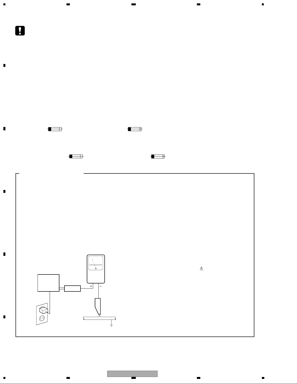
LEAKAGE CURRENT CHECK
Measure leakage current to a known earth ground
(water pipe, conduit, etc.) by connecting a leakage
current tester such as Simpson Model 229-2 or
D
E
equivalent between the earth ground and all exposed
metal parts of the appliance (input/output terminals,
screwheads, metal overlays, control shaft, etc.). Plug
the AC line cord of the appliance directly into a 120V
AC 60 Hz outlet and turn the AC power switch on. Any
current measured must not exceed 0.5 mA.
Reading should
not be above
0.5 mA
Earth
ground
Device
under
test
Also test with
plug reversed
(Using AC adapter
plug as required)
Test all
exposed metal
surfaces
Leakage
current
tester
AC Leakage Test
ANY MEASUREMENTS NOT WITHIN THE
LIMITS OUTLINED ABOVE ARE INDICATIVE
OF A POTENTIAL SHOCK HAZARD AND
MUST BE CORRECTED BEFORE RETURNING THE APPLIANCE TO THE CUSTOMER.
2. PRODUCT SAFETY NOTICE
Many electrical and mechanical parts in the appliance
have special safety related characteristics. These are
often not evident from visual inspection nor the
protection afforded by them necessarily can be obtained
by using replacement components rated for voltage,
wattage, etc. Replacement parts which have these
special safety characteristics are identified in this
Service Manual.
Electrical components having such features are
identified by marking with a
on the parts list in this Service Manual.
The use of a substitute replacement component which
does not have the same safety characteristics as the
PIONEER recommended replacement one, shown in the
parts list in this Service Manual, may create shock, fire,
or other hazards.
Product Safety is continuously under review and new
instructions are issued from time to time. For the latest
information, always consult the current PIONEER
Service Manual. A subscription to, or additional copies
of, PIONEER Service Manual may be obtained at a
nominal charge from PIONEER.
on the schematics and
F
2
1234
DV-363-S
5678
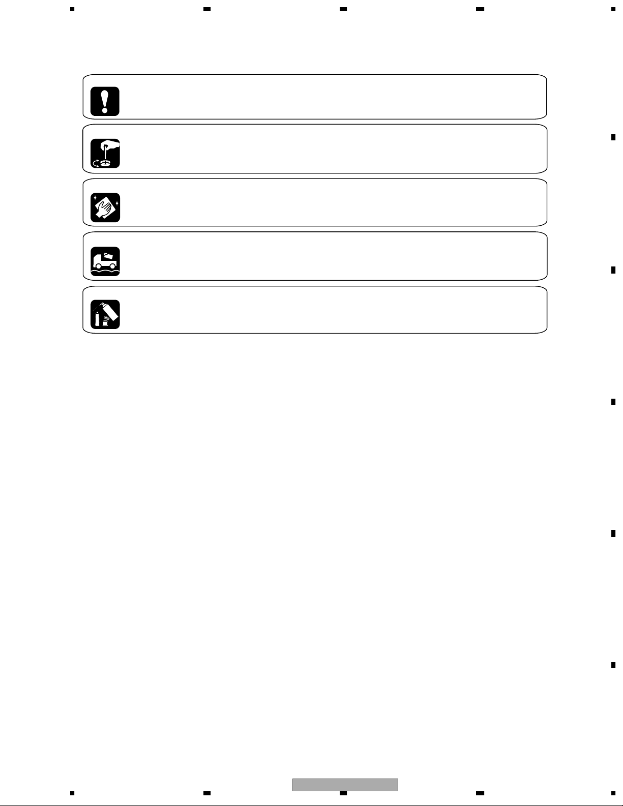
[ Important symbols for good services ]
In this manual, the symbols shown-below indicate that adjustments, settings or cleaning should be made securely.
When you find the procedures bearing any of the symbols, be sure to fulfill them:
1. Product safety
You should conform to the regulations governing the product (safety, radio and noise, and other regulations), and
should keep the safety during servicing by following the safety instructions described in this manual.
2. Adjustments
To keep the original performances of the product, optimum adjustments or specification confirmation is indispensable.
In accordance with the procedures or instructions described in this manual, adjustments should be performed.
3. Cleaning
For optical pickups, tape-deck heads, lenses and mirrors used in projection monitors, and other parts requiring cleaning,
proper cleaning should be performed to restore their performances.
4. Shipping mode and shipping screws
To protect the product from damages or failures that may be caused during transit, the shipping mode should be set or
the shipping screws should be installed before shipping out in accordance with this manual, if necessary.
A
B
5. Lubricants, glues, and replacement parts
Appropriately applying grease or glue can maintain the product performances. But improper lubrication or applying
glue may lead to failures or troubles in the product. By following the instructions in this manual, be sure to apply the
prescribed grease or glue to proper portions by the appropriate amount.For replacement parts or tools, the prescribed
ones should be used.
C
D
56
DV-363-S
E
F
7
8
3

1234
CONTENTS
SAFETY INFORMATION..................................................................................................................................... 2
A
B
C
D
1. SPECIFICATIONS ............................................................................................................................................ 5
2. EXPLODED VIEWS AND PARTS LIST ............................................................................................................ 6
2.1 PACKING ................................................................................................................................................... 6
2.2 EXTERIOR SECTION................................................................................................................................ 8
2.3 FRONT PANEL SECTION ....................................................................................................................... 10
2.4 LOADING MECHA ASSY ........................................................................................................................12
2.5 TRAVERSE MECHA ASSY-S .................................................................................................................. 14
3. BLOCK DIAGRAM AND SCHEMATIC DIAGRAM..........................................................................................16
3.1 BLOCK DIAGRAM ................................................................................................................................... 16
3.2 WAVEFORMS .......................................................................................................................................... 18
3.3 LOAB ASSY and OVERALL WIRING DIAGRAM..................................................................................... 20
3.4 DVDM ASSY 1/3 [FRONT END BLOCK] ................................................................................................. 22
3.5 DVDM ASSY 2/3 [BACK END BLOCK].................................................................................................... 24
3.6 DVDM ASSY 3/3 [AUDIO/VIDEO BLOCK]............................................................................................... 26
3.7 FLKY and PWSB ASSYS ........................................................................................................................ 28
3.8 POWER SUPPLY UNIT [VWR1365]........................................................................................................ 30
3.9 POWER SUPPLY UNIT [VWR1367]........................................................................................................ 31
4. PCB CONNECTION DIAGRAM ..................................................................................................................... 33
4.1 LOAB ASSY............................................................................................................................................. 33
4.2 DVDM ASSY............................................................................................................................................ 34
4.3 FLKY and PWSB ASSYS ........................................................................................................................ 38
4.4 POWER SUPPLY UNIT [VWR1365]........................................................................................................ 40
4.5 POWER SUPPLY UNIT [VWR1367]........................................................................................................ 41
5. PCB PARTS LIST ........................................................................................................................................... 42
6. ADJUSTMENT ............................................................................................................................................... 44
6.1 ADJUSTMENT ITEMS AND LOCATION ................................................................................................. 44
6.2 JIGS AND MEASURING INSTRUMENTS............................................................................................... 44
6.3 NECESSARY ADJUSTMENT POINTS ...................................................................................................45
6.4 TEST MODE ............................................................................................................................................ 46
6.5 MECHANISM ADJUSTMENT.................................................................................................................. 47
7. GENERAL INFORMATION............................................................................................................................. 50
7.1 DIAGNOSIS ............................................................................................................................................. 50
7.1.1 TEST MODE ......................................................................................................................................... 50
7.1.2 DISPLAY SPECIFICATION OF THE TEST MODE ............................................................................... 52
7.1.3 FUNCTIONAL SPECIFICATION OF THE SHORTCUT KEY................................................................ 53
7.1.4 SPECIFICATION OF MODEL INFORMATION DISPLAY...................................................................... 54
7.1.5 FUNCTIONAL SPECIFICATION OF THE SERVICE MODE................................................................. 55
7.1.6 MECHANICAL ERROR HISTORY........................................................................................................ 56
7.1.7 ID NUMBER AND ID DATA SETTING................................................................................................... 59
7.1.8 SEQUENCE AFTER POWER ON ........................................................................................................ 62
7.1.9 DISASSEMBLY ..................................................................................................................................... 63
7.2 IC ............................................................................................................................................................. 70
7.3 DISC / CONTENT FORMAT PLAYBACK COMPATIBILITY ..................................................................... 84
7.4 CLEANING............................................................................................................................................... 85
8. PANEL FACILITIES ........................................................................................................................................ 86
E
F
4
1234
DV-363-S
General
System . . . . . . . . . . . . . . . . . . . . . . . . DVD player
Power requirements . . . . . . . . . . AC 120 V, 60 Hz
Power consumption . . . . . . . . . . . . . . . . . . . 11 W
Power consumption (standby) . . . . . . . . . . 0.12 W
Weight . . . . . . . . . . . . . . . . . . . . . 2.3 kg / 5 lb 1 oz
Dimensions:
DV-363. . . . . . . . . . 420 (W) x 55 (H) x 283 (D) mm
(16.5 (W) x 2.2 (H) x 11.1 (D) in.)
Operating temperature . . . . . . . . . +5°C to +35°C
(+41°F to +95°F)
Operating humidity . . . . . . . . . . . . . . . 5% to 85%
(no condensation)
Component video output
Y (luminance) - Output level . . . . . . . 1 Vp-p (75 Ω)
P
B
(color) - Output level . . . . . . . . . 0.7 Vp-p (75 Ω)
P
R
(color) - Output level . . . . . . . . . 0.7 Vp-p (75 Ω)
Jack. . . . . . . . . . . . . . . . . . . . . . . . . . . . RCA jacks
S-video output
Y (luminance) - Output level . . . . . . . 1 Vp-p (75 Ω)
C (color) - Output level . . . . . . . .286 mVp-p (75 Ω)
Jack. . . . . . . . . . . . . . . . . . . . . . . . . . .S-video jack
Video output
Output level . . . . . . . . . . . . . . . . . . . 1 Vp-p (75 Ω)
Jack. . . . . . . . . . . . . . . . . . . . . . . . . . . . . RCA jack
Audio output (1 stereo pair)
Output level . . . . . . . . . . . . . . During audio output
200 mVrms (1 kHz, –20 dB)
Number of channels . . . . . . . . . . . . . . . . . . . . . . 2
Jacks . . . . . . . . . . . . . . . . . . . . . . . . . . . . RCA jack
Digital audio characteristics
Frequency response . . . . . . . . . . . 4 Hz to 44 kHz
(DVD fs: 96 kHz)
S/N ratio . . . . . . . . . . . . . . . . . . . . . . . . . . .115 dB
Dynamic range . . . . . . . . . . . . . . . . . . . . . . 101 dB
Total harmonic distortion . . . . . . . . . . . . 0.0016 %
Wow and flutter. . . . . . . . . Limit of measurement
(±0.001% W. PEAK) or lower
Digital output
Optical digital output . . . . . . . . .Optical digital jack
Coaxial digital output . . . . . . . . . . . . . . . .RCA jack
Accessories
• The specifications and design of this
product are subject to change without
notice, due to improvement.
Audio/video cable . . . . . . . . . . . . . . . . . . . . . . . .1
Power cable . . . . . . . . . . . . . . . . . . . . . . . . . . . . 1
Remote control . . . . . . . . . . . . . . . . . . . . . . . . . 1
AA/R6P dry cell batteries. . . . . . . . . . . . . . . . . . . 2
Operating Instructions (KU model) . . . . . . . . . . . 1
Operating Instructions (KC model) . . . . . . . . . . . 2
Warranty card . . . . . . . . . . . . . . . . . . . . . . . . . . . 1
• Manufactured under license from Dolby
Laboratories. “Dolby” and the double-D symbol
are trademarks of Dolby Laboratories.
• “DTS” and “DTS Digital Out” are registered
trademarks of Digital Theater Systems, Inc.
• TruSurround and the symbol are
trademarks of SRS Labs, Inc. TruSurround technology is incorporated under license from SRS
Labs, Inc.
5678
1. SPECIFICATIONS
A
B
C
D
56
DV-363-S
7
E
F
5
8
1234
2. EXPLODED VIEWS AND PARTS LIST
NOTES:
A
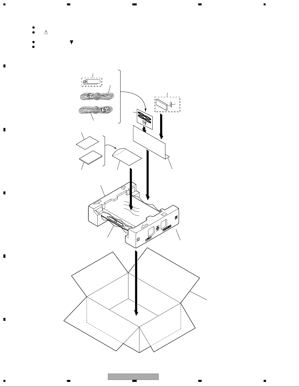
2.1 PACKING
B
C
Parts marked by "NSP" are generally unavailable because they are not in our Master Spare Parts List.
The mark found on some component parts indicates the importance of the safety factor of the part.
Therefore, when replacing, be sure to use parts of identical designation.
Screws adjacent to mark on product are used for disassembly.
For the applying amount of lubricants or glue, follow the instructions in this manual.
(In the case of no amount instructions, apply as you think it appropriate.)
5
2
3
4
9
1
8
"Operating Instructions"
6, 7
11
D
E
9
10
14
12
13
F
6
1234
DV-363-S
>
5678
PACKING parts List
Mark
No. Description Part No.
1 Power Cable ADG7021
2 Audio / Video Cable VDE1077
3 Remote Control VXX2865
4 Battery Cover VNK4997
NSP 5 AA/R6P Dry Cell Batteries VEM1030
6 Operating Instructions VRB1307
(English)
7 Operating Instructions See Contrast table (2)
(French)
Mark
No. Description Part No.
NSP 8 Warranty Card See Contrast table (2)
9 Polyethylene Bag VHL1051
10 Sheet Z23-007
11 Pad L VHA1319
12 Pad R VHA1320
13 Packing Case See Contrast table (2)
14 Paper Board VHC1100
A
(2) CONTRAST TABLE
DV-363-S/KUXU, KCXU, KUXQ, DV-363-K/KUXU, KCXU and KUXQ are constructed the same except for the following :
Mark No. Symbol and Description DV-363-S/KUXU DV-363-S/KCXU DV-363-S/KUXQ DV-363-K/KUXU DV-363-K/KCXU DV-363-K/KUXQ
7 Operating Instructions Not used VRC1173 Not used Not used VRC1173 Not used
(French)
NSP 8 Warranty Card ARY7063 ARY7045 ARY7063 ARY7063 ARY7045 ARY7063
13 Packing Case VHG2300 VHG2345 VHG2358 VHG2298 VHG2344 VHG2349
B
C
D
56
DV-363-S
E
F
7
8
7
1234
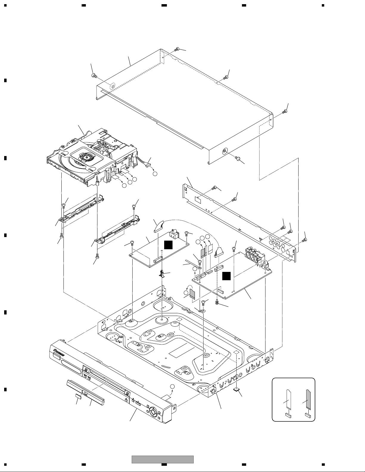
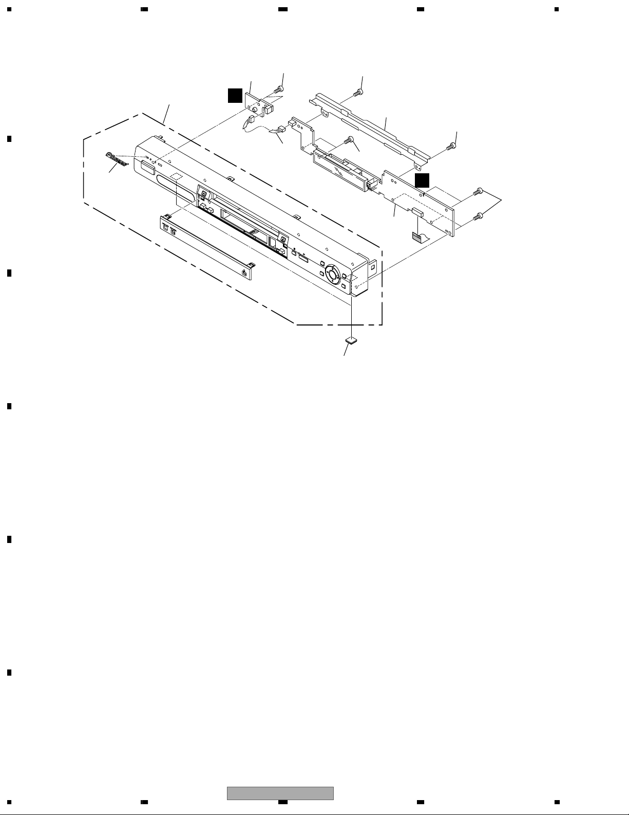
2.2 EXTERIOR SECTION
A
B
C
"2.4 LOADING MECHA. ASSY".
Refer to
3
21
19
12
21
22
21
21
19
21
18
6
D
C
B
E
21
4
14
22
D
E
15
22
20
2
E
10
20
D
C
B
20
8
E
20
B
A
5
13
A
20
1
7
21
21
22
9
16
17
Refer to
F
8
1234
"2.3 FRONT PANEL SECTION".
DV-363-S
11
NON-CONTACT
SIDE
CONTACT SIDE
>
5678
EXTERIOR SECTION parts List
Mark
Mark
No. Description Part No.
1 DVDM Assy VWS1555
2 POWER SUPPLY Unit VWR1365
(or VWR1367)
NSP 3 Loading Mecha. Assy VWT1207
4 Connector Assy PF13PP-D27
5 Flexible Cable (15P) VDA1963
6 Connector Assy (5P) VKP2301
NSP 7 PCB Spacer (3X6) AEC7156
8 Cord Clamper RNH-184
9 Rubber Foot VEB1349
10 PCB Support VEC2184
NSP 11 Base Chassis VNA2614
No. Description Part No.
12 Rear Panel See Contrast table (2)
13 PCB Base VNE2278
14 Adapter 3L VNL1960
15 Adapter 3R VNL1961
16 DVD V Plate See Contrast table (2)
17 Tray Panel See Contrast table (2)
18 Bonnet Case S See Contrast table (2)
19 Screw See Contrast table (2)
20 Screw BBZ30P060FMC
21 Screw BBZ30P080FZK
22 Screw PPZ30P080FMC
(2) CONTRAST TABLE
DV-363-S/KUXU, KCXU, KUXQ, DV-363-K/KUXU, KCXU and KUXQ are constructed the same except for the following :
Mark No. Symbol and Description DV-363-S/KUXU DV-363-S/KCXU DV-363-S/KUXQ DV-363-K/KUXU DV-363-K/KCXU DV-363-K/KUXQ
12 Rear Panel VNA2536 VNA2536 VNA2536 VNA2533 VNA2533 VNA2533
16 DVD V Plate VAM1135 VAM1135 VAM1135 VAM1120 VAM1120 VAM1120
17 Tray Panel VNK5196 VNK5196 VNK5196 VNK5194 VNK5194 VNK5194
18 Bonnet Case S VXX2874 VXX2874 VXX2874 VXX2873 VXX2873 VXX2873
19 Screw BCZ40P060FNI BCZ40P060FNI BCZ40P060FNI BCZ40P060FZK BCZ40P060FZK BCZ40P060FZK
A
B
C
D
E
F
56
DV-363-S
7
8
9
1234
2.3 FRONT PANEL SECTION
A
6
7
B
C
2
D
8
3
8
4
8
8
C
8
1
5
D
E
F
10
1234
DV-363-S
5678
FRONT PANEL SECTION parts List
Mark
Mark
No. Description Part No.
1 FLKY Assy VWG2418
2 PWSB Assy VWG2424
3 Connector Assy PF03PP-B07
4 FP Angle VNE2300
5 Rubber Foot VEB1349
No. Description Part No.
6 Front Panel Assy See Contrast table (2)
7 Pioneer Name Plate See Contrast table (2)
8 Screw PPZ30P080FMC
(2) CONTRAST TABLE
DV-363-S/KUXU, KCXU, KUXQ, DV-363-K/KUXU, KCXU and KUXQ are constructed the same except for the following :
Mark No. Symbol and Description DV-363-S/KUXU DV-363-S/KCXU DV-363-S/KUXQ DV-363-K/KUXU DV-363-K/KCXU DV-363-K/KUXQ
6 Front Panel Assy VXA2561 VXA2561 VXA2561 VXA2552 VXA2552 VXA2552
7 Pioneer Name Plate VAM1129 VAM1129 VAM1129 VAM1130 VAM1130 VAM1130
A
B
C
D
E
56
DV-363-S
F
7
8
11
1234
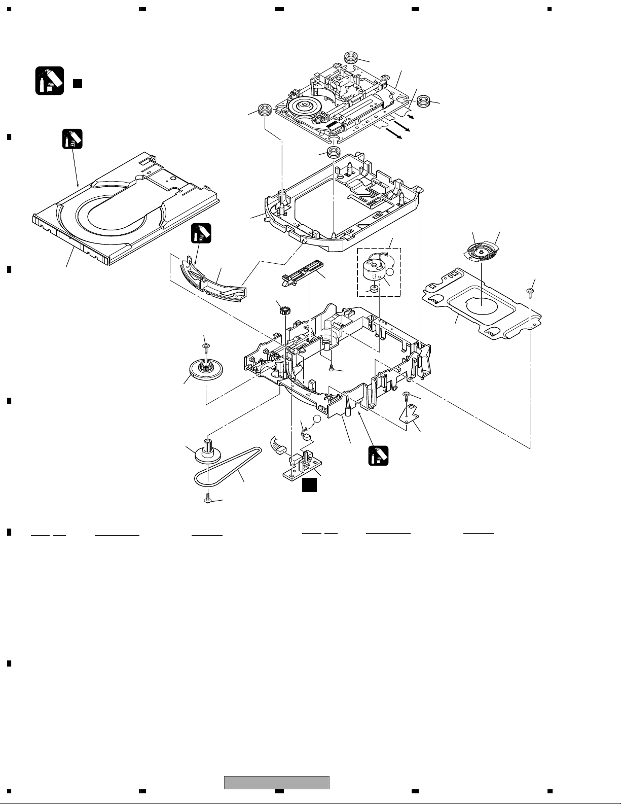
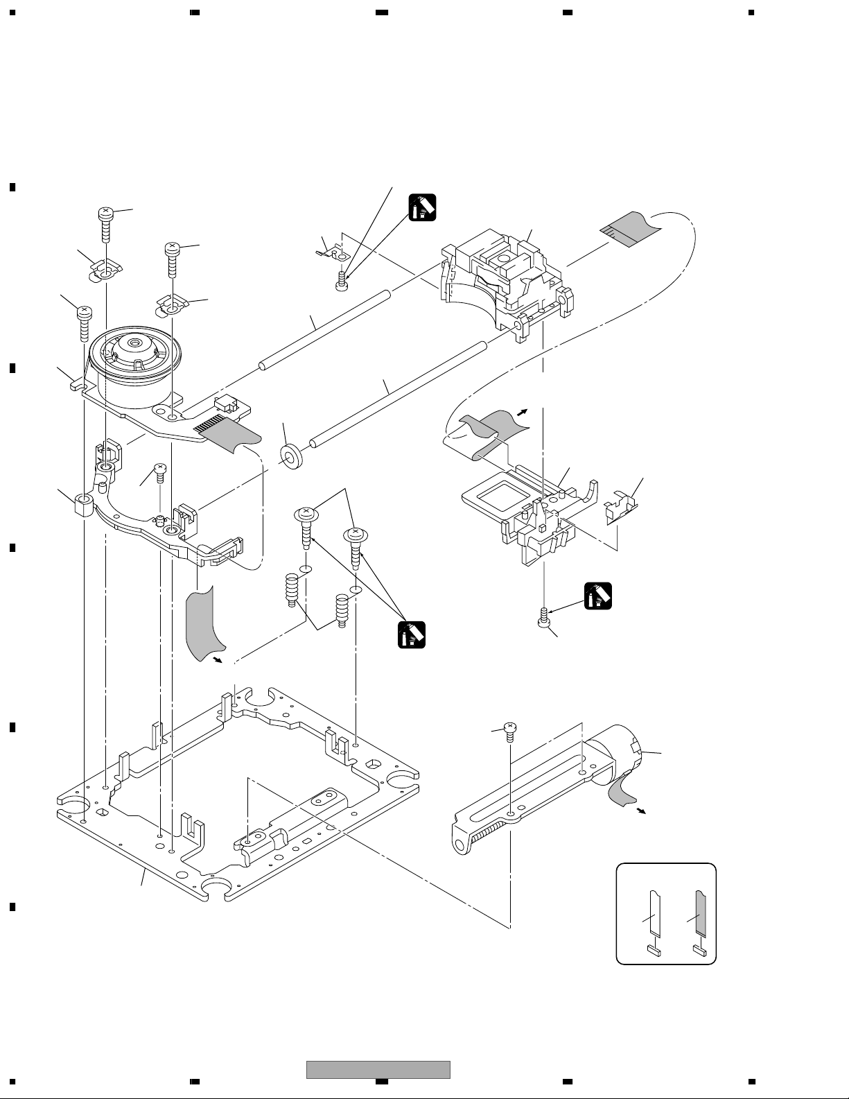
2.4 LOADING MECHA ASSY
Note :
A
Refer to
" Application of Lubricant".
8
Daifree
GEM1036
B
12
Lubricating Oil
GYA1001
23
C
13
16
22
8
17
8
4
Refer to
2
"2.5 TRAVERSE MECHA. ASSY-S".
6
8
To DVDM CN101 (Pickup Assy-S)
To DVDM CN104 (Stepping Motor)
To DVDM CN102 (Spindle Motor)
3
A
5
18
19
20
22
D
LOADING MECHA ASSY parts List
Mark
No. Description Part No.
NSP 1 LOAB Assy VWG2426
2 Traverse Mecha. Assy-S VXX2871
3 Loading Motor Assy VXX2872
4 Motor Pulley PNW1634
5 Motor VXM1105
E
6 Flexible Cable (24P) VDA1945
7 Connector Assy 2P VKP2253
8 Floating Rubber VEB1351
9 Belt VEB1330
10 Stabilizer VNE2253
15
14
22
21
22
7
A
10
11
9
1
A
Mark No. Description Part No.
17 SW Lever VNL1925
18 Clamper Plate VNE2251
19 Bridge VNE2252
20 Clamper VNL1924
21 Screw JGZ17P028FMC
22 Screw Z39-019
23 Tray VNL1920
Lubricating Oil
GYA1001
11 Loading Base VNL1917
12 Float Base DVD VNL1918
13 Drive Cam VNL1919
14 Gear Pulley VNL1921
F
15 Loading Gear VNL1922
16 Drive Gear VNL1923
12
1234
DV-363-S
5678
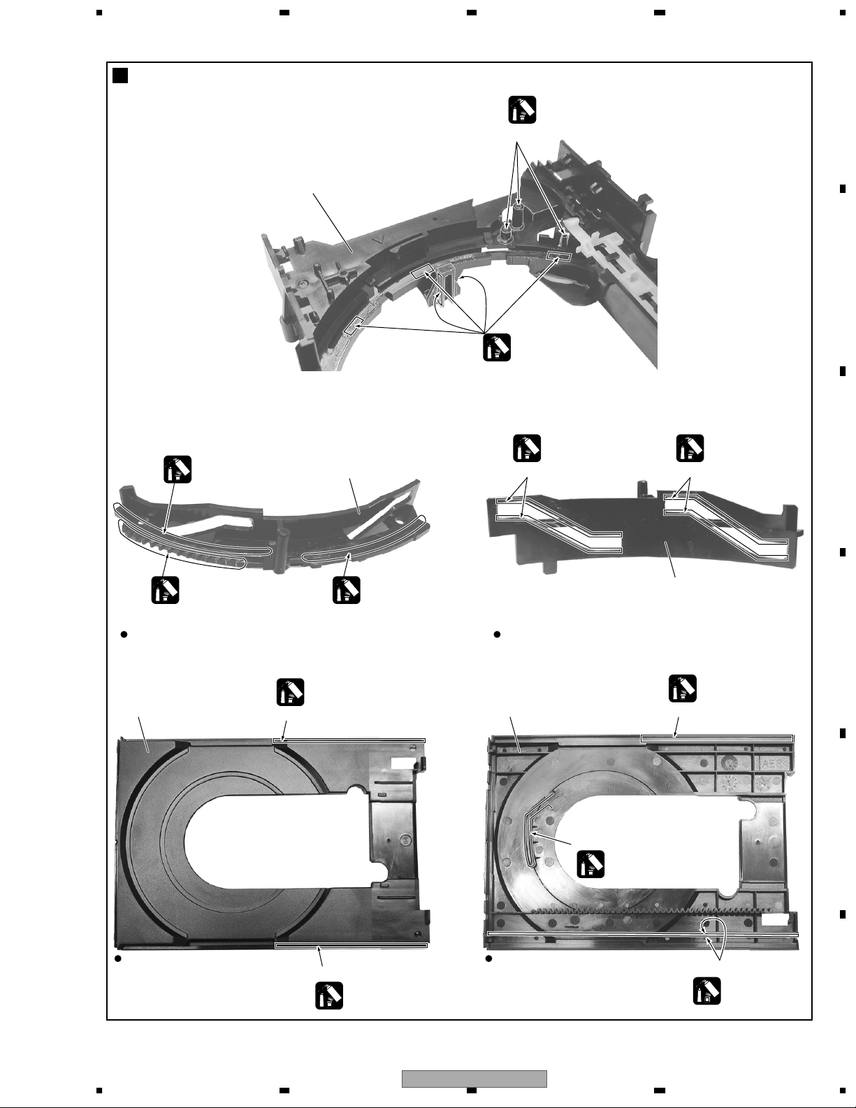
Application of Lubricant
Lubricating Oil
GYA1001
Around the shaft
No. 11
Loading Base
No. 23
Tray
No. 13
Drive Cam
No. 13
Drive Cam
No. 23
Tray
Front View Rear View
Daifree
GEM1036
Inner side of a ditch
Concave of unevenness
Top View
Bottom View
Daifree
GEM1036
Daifree
GEM1036
Side of the rib
Lubricating Oil
GYA1001
Concave of unevenness
Daifree
GEM1036
Concave of unevenness
Daifree
GEM1036
Lubricating Oil
GYA1001
Lubricating Oil
GYA1001
Lubricating Oil
GYA1001
Inner side of a ditch
Lubricating Oil
GYA1001
Inner side of a ditch
Lubricating Oil
GYA1001
A
B
C
D
E
DV-363-S
56
7
F
13
8
1234
2.5 TRAVERSE MECHA ASSY-S
A
15 (Torque : 0.15 ± 0.01 N•m)
17
8
10
B
17
1
17
10
7
6
Silicone Adhesive
GEM1037
3
To
DVDM CN101
(Pickup Assy)
12
C
13
16
4 (Adjustment screw)
14
9
Silicone Adhesive
GEM1037
D
To DVDM CN102
(Spindle Motor)
5
(Adjustment
spring)
Screw Tight
GYL1001
15 (Torque : 0.15 ± 0.01 N•m)
16
2
E
To
DVDM CN104
(Stepping Motor)
11
NON-CONTACT
F
SIDE
CONTACT SIDE
14
1234
DV-363-S

5678
TRAVERSE MECHA ASSY-S parts List
Mark
No. Description Part No.
1 Spindle Motor VXM1099
2 Stepping Motor VXM1101
3 Pickup Assy-S OXX8005
4 Skew Screw VBA1080
5 Skew Spring VBH1335
6 Guide Bar VLL1514
7 Sub Guide Bar VLL1515
8 Leaf Spring VNC1023
9 Joint Spring VNC1019
10 Support Spring VNC1020
NSP 11 Mecha.Chassis VNE2248
12 Damper Sheet VEB1335
13 Spacer VNL1913
14 Joint 03 VNL1949
15 Tapping Screw OBA8016
16 Screw BBZ20P050FZK
17 Screw PMA26P100FMC
A
B
C
D
E
56
DV-363-S
F
7
8
15
1234
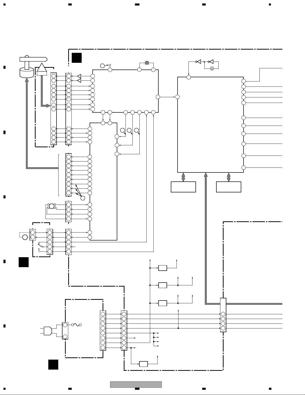
3. BLOCK DIAGRAM AND SCHEMATIC DIAGRAM
3.1 BLOCK DIAGRAM
A
X301
DVDM ASSY
B1
B2
B3
B4
A
C
H3H3+
H2H2+
H1H1+
A1
A2
A3
ST2-
ST2+
ST1+
ST1-
CN101
(24P)
18
9
10
3
4
8
6
21
22
23
24
CN102
(12P)
4
5
6
7
8
9
10
11
12
CN104
1
2
3
4
CN103
1
2
3
4
B
Q201,Q202
Q211,Q212
17
CLOSE
V+3D
OPEN
89
90
14
12
21
20
30
31
34
35
16
17
18
19
20
21
14
13
12
6
5
9
10
36
37
RF(TP)
99
RFSACD FROUT FRIN
LD1
LD2
A
6
B
8
C
D
E
F
TOTO+
FOFO+
HW-
HW+
HV-
FTS DRIVER
HV+
HUHU+
U
V
W
27 28
M63018FP
Focus,
Tracking,
Stepper,
Spindle,
Loading
IC301
STM6316ATXXA
FRONT END IC
• RF Demodulation
• Servo Control
• Servo Decode
• Error Correction
34
SPIN
TOIN
FG
PC(0)FACT
3633
2116 15
24
26
40
TACT
FOIN
LOIN+
IC101
Drive
and
SL2-
FG
SL2+
Detection
SL1+
SL1-
LO+
LO-
CN1013
SPINDLE
MOTOR
B
OEIC
PICKUP
ASSY-S
(24P)
LD(650)
7
LD(780)
9 16
16
15
22
21
17
19
T DRV
4
T RTN
3
F DRV
2
F RTN
1
C
STEPPING
MOTOR
D
CN602
2 1
+–
1 2
M
LOADING
MOTOR
ASSY
LOAB ASSY
A
CN601
S101
M
LOAD-
LOAD+
SW2
3
V+3D
4
SW1
5 5
20MHz
86
OUT_DATA
PC(6)55PD(0)70PE(1)38PC(2)
44
FG
CLOSE
SPDL PDM
LOAD DRV
V+6B
87
FE DATA
64 16
OPEN
IC401
MM1565AF
5V REG.
VYW2092
FLASH ROM
V+5
IC604 TC7WU04FU
532 6
120
PIXCLK
B_DATA
STM5589CVA
BACK END IC
• System Control
• MPEG Video Decode
• Video Encode
• Video DAC
• Audio Decode
(MP3, Dolby)
• Sub-picture Decode
IC603
(2/3)(3/3)
X601
27MHz
IC601
K4S641632F-TC75
DAC_SCLK
PCM DATA0
PCKCLK
LRCLK
CV_OUT
C_OUT
Y_OUT
G_OUT
B_OUT
R_OUT
IC602
64M SDRAM
SPDIF
57
51
52
55
56
34
33
32
26
25
27
D OUT
A BCK
A DATA0
A MCLK
A LRCK
V
S_C
S_Y
G/Y
B/Cb
R/Cr
IC402
PQ1L333M2SP
3V REG.
V+3_FEA
E
CN101
(CN2)
AC IN
LIVE
NEUTRAL
(13P)
CN1
1
2
13
12
11
8
7
5
4
2
-28V
FL DC+
FL DC-
EV+3.3V
SW+1.8V
EV+6V(A)
EV+6V(B)
SW+12V
F
POWER SUPPLY
E
UNIT
16
CN401
(13P)
13
12
11
8
7
5
4
2
DV-363-S
V+6
V+12
IC703
NJM78L05UA
5V REG.
IC403
PQ1L333M2SP
3V REG.
V+1R8
V+1R8_BE
V+1R8_FEA
V+1R8_FED
V+5A
V+3A
V+3E
V+3_BE
V+3_FED
CN105
(15P)
-28V
4
FL DC+
6
FL DC-
2
+3.3V
5
1234
R651
R652
R655
R656
4 7
8
3
5 6
5678
A
1– $: Refer to "3.2 WAVEFORMS".
JA701
IC701 PCM1742KE
AUDIO DAC
BCKIN
1
DATA
2
MCLK
16
LRCKIN
3
7
8
VOUTL
VOUTR
IC702 (1/2)
BA4560F
AUDIO LPF
2
1
3
OPTICAL
Q791
COAXIAL
L
R
ANALOG
AUDIO
OUTPUT
DIGITAL
AUDIO
OUTPUT
B
V OUT
V IN
4
C OUT
C IN
2
Y OUT
Y IN
6
CY OUT
CY IN
10
Cb OUT
Cb IN
12
Cr OUT
Cr IN
14
IC801
MM1623AF
Video Driver Amp.
• LPF
• AMP
• Driver
9
23
26
21
20
18
16
14
13
10
11
12
C832
C812
C822
C842
C852
C862
C
Y
COMPOSITE
VIDEO
OUTPUT
S VIDEO
OUTPUT
Y
COMPONENT
VIDEO
Cb
OUTPUT
Cr
C
JA801
D
CN101
12
10
14
11
(15P)
V+3E
IR101
Remote Sensor
Unit
• Main Unit Key Input
RPM7240-H4
• Remote Control Receive
• FL Display Control
SEL IR
17
KEY0
22
KEY1 - KEY2
20-21
43
FLKY ASSY
C
CN102
(3P)
KEY
1 1
CN103
(3P)
PWSB ASSY
D
-28V
60
IC101 PE5374A
FL CONTROL
MICROCOMPUTER
X1 X2
X101
5MHz
FL101
FL TUBE
DV-363-S
56
E
F
7
8
17
1234
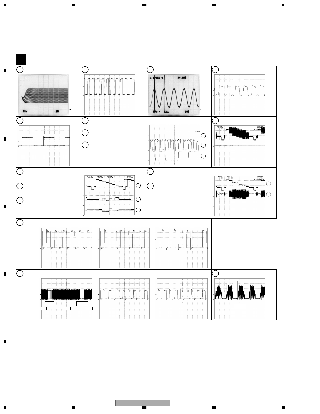
3.2 WAVEFORMS
Note : The encircled numbers denote measuring point in the schematic diagram.
A
Measurement condition
No. 3 to 8 : reference A1 (DVD), T2-chp 1
DVDM ASSY
B
IC301 - pin 99 [RF]
1
V: 200mV/div. H: 0.1µsec/div.
: No. 1 to 2 and 9 to 14 : reference A1 (DVD), T2-chp 19, Color-bar
IC301 - pin 36 [FG]
2
V: 1V/div. H: 5msec/div.
Foot of R655 (IC701 - pin 16)
3
[AUDIO DAC -MCLK]
V: 1V/div. H: 20nsec/div.
Foot of R651 (IC701 - pin 1)
4
[AUDIO DAC -BCK]
V: 2V/div. H: 200nsec/div.
B
GND
Foot of R656 (IC701 - pin 3)
5
[AUDIO DAC -LRCK]
V: 2V/div. H: 5µsec/div.
Foot of C842 (IC801 - pin 20)
10
C
[Component Video out -Y]
V: 1V/div. H: 10µsec/div.
Foot of C852 (IC801 - pin 18)
11
[Component Video out -Pb]
V: 2V/div. H: 10µsec/div.
Foot of C862 (IC801 - pin 16)
12
[Component Video out -Pr]
V: 2V/div. H: 10µsec/div.
IC301 - pin 55 [LOAD_DRV]
15
V: 1V/div. H: 500nsec/div.
Foot of R656 (IC701 - pin 3)
6
[AUDIO DAC -LRCK]
Foot of R651 (IC701 - pin 1)
7
[AUDIO DAC -BCK]
Foot of R652 (IC701 - pin 2)
8
[AUDIO DAC -DATA]
(Waveform of DATA is unsettled.)
V: 2V/div. H: 500nsec/div.
Foot of C822 (IC801 - pin 21)
13
[S Video out -Y]
V: 1V/div. H: 10µsec/div.
10
11
12
Foot of C812 (IC801 - pin 26)
14
[S Video out -C]
V: 1V/div. H: 10µsec/div.
GND
6
7
8
Foot of C832 (IC801 - pin 23)
9
[Composite Video out]
V: 1V/div. H: 10µsec/div.
13
14
D
[Tray stops] [Tray is opening] [Tray is closing]
IC301 - pin 44 [SPDL_PDM]
16
Brakes
E
ON
V: 2V/div. H: 1sec/div. V: 2V/div. H: 500nsec/div. V: 2V/div. H: 500nsec/div.
Accelertar
STOPPLAY PLAY
ON
[PLAY][PLAY→STOP→PLAY] [STOP]
CN102 - pin10, 11, 12
17
(IC101 - pin 14, 13, 12)
[FTS Driver -A1, A2, A3]
[PLAY]
V: 2V/div. H: 2msec/div.
F
18
DV-363-S
1234

5678
A
B
C
D
E
56
DV-363-S
F
7
8
19
1234
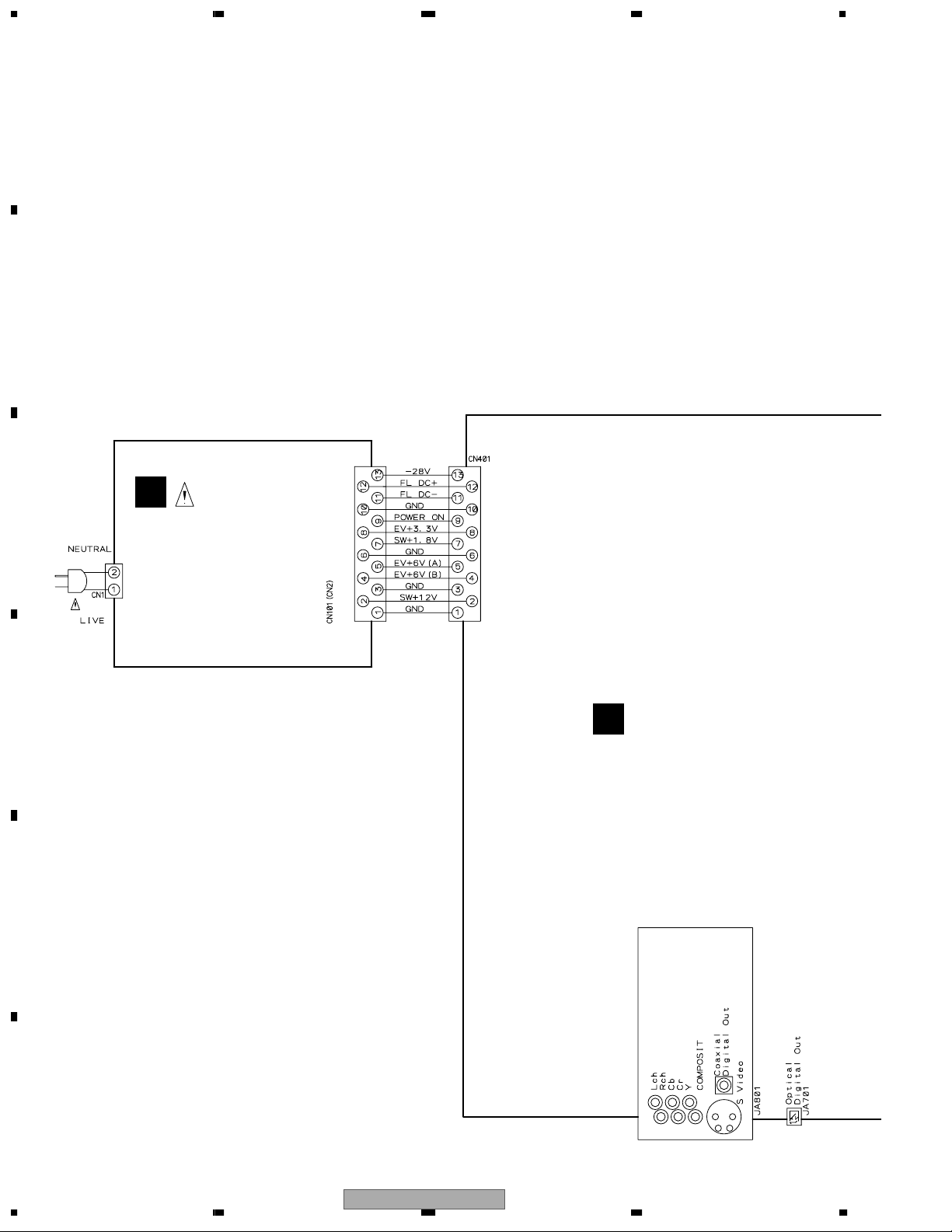
3.3 LOAB ASSY and OVERALL WIRING DIAGRAM
A
B
Note : When ordering service parts, be sure
to refer to "EXPLODED VIEWS and
PARTS LIST" or "PCB PARTS LIST".
E
C
D
POWER SUPPLY UNIT
(VWR1365)
( or VWR1367)
DVDM ASSY
B
(VWS1555)
E
F
20
1234
DV-363-S
5678
(F)
: FOCUS SERVO LOOP LINE
(T)
: TRACKING SERVO LOOP LINE
(S)
: STEPPING SERVO LOOP LINE
A
FLKY ASSY
C
(VWG2418)
F
F
T
T
F
F
PWSB ASSY
D
(VWG2424)
PICKUP ASSY-S
(OXX8005)
B
C
F
T
T
F
STEPPING MOTOR
S
S
S
: VXM1101
S
SPINDLE
MOTOR
: VXM1099
LOADING
MOTOR ASSY
: VXX2872
D
E
LOAB ASSY
A
(VWG2426)
F
56
DV-363-S
A
7
8
21
1234
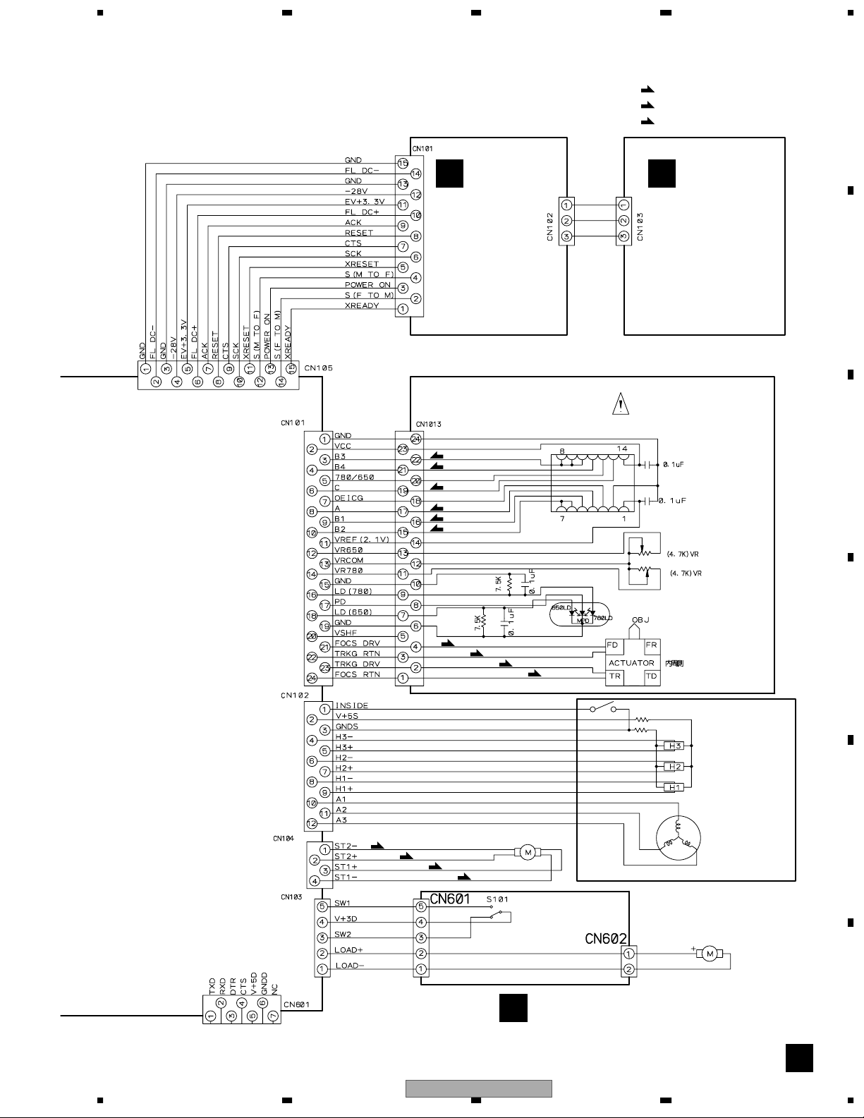
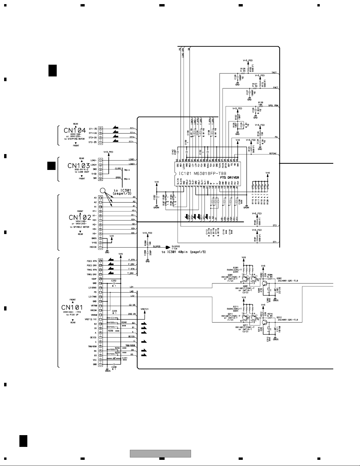
3.4 DVDM ASSY 1/3 [FRONT END BLOCK]
A
B 1/3
B
STEPPING
MOTOR
DVDM ASSY (VWS1555)
S
S
S
S
A
CN601
C
SPINDLE
MOTOR
17
SSS
S
F
F
D
T
T
PICKUP
ASSY-S
F
F
T
T
E
F
F
F
B 1/3
22
1234
DV-363-S

5678
A
B
1, 2, @– $: Refer to "3.2 WAVEFORMS".
B
2/3
15
C
16
D
1
2
F
F
F
F
T
T
DV-363-S
56
(F)
: FOCUS SERVO LOOP LINE
(T)
: TRACKING SERVO LOOP LINE
(S)
: STEPPING SERVO LOOP LINE
E
F
B 1/3
7
8
23
1234
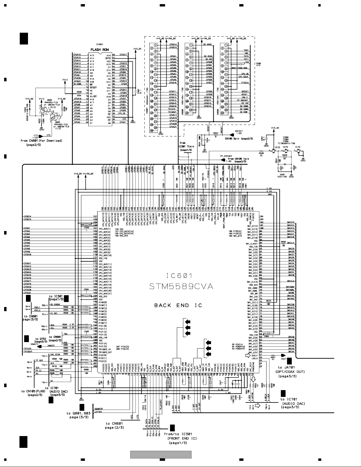
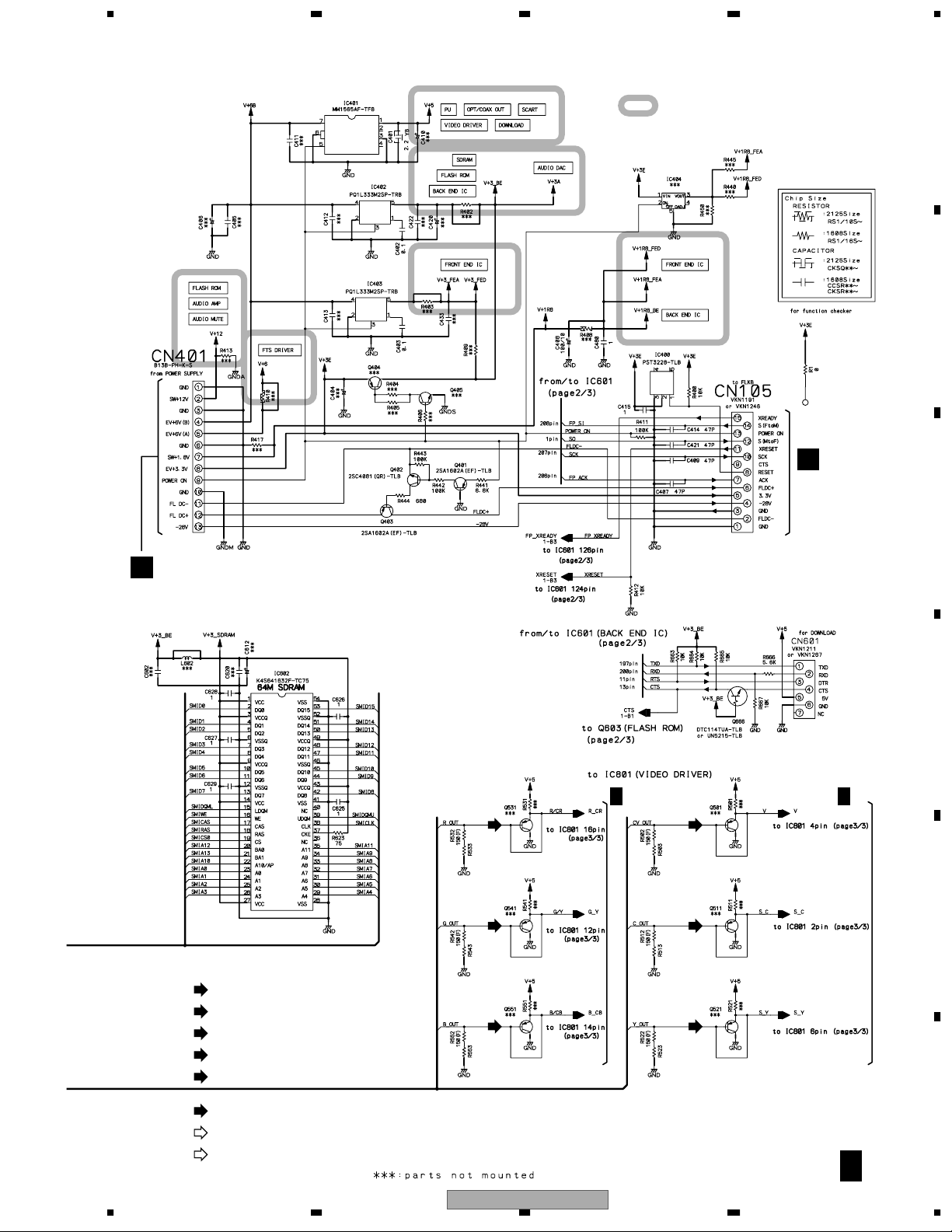
3.5 DVDM ASSY 2/3 [BACK END BLOCK]
A
B
C
B 2/3
DVDM ASSY (VWS1555)
VYW2092
D
B
3/3
B
3/3
E
F
B
1/3
B/Cb
G/Y
R/Cr
S-Y
S-C
V
B
3/3
B
3/3
B
1/3
D
B
3/3
B
3/3
B 2/3
24
1234
DV-363-S
5678
: The power supply is shown with
the marked box.
C
CN101
A
B
C
E
VWR1365: CN101
VWR1367: CN2
: V SIGNAL ROUTE
V
: S-VIDEO OUT C SIGNAL ROUTE
S-C
: S-VIDEO OUT Y SIGNAL ROUTE
S-Y
: R/Cr SIGNAL ROUTE
R/Cr
: G/Y SIGNAL ROUTE
G/Y
R/Cr
151515
G/Y
B/Cb
D
B
3/3
V
151515
S-C
S-Y
B
3/3
E
: B/Cb SIGNAL ROUTE
B/Cb
: AUDIO SIGNAL ROUTE
: AUDIO(DIGITAL) SIGNAL ROUTE
D
DV-363-S
56
F
B 2/3
7
8
25
1234
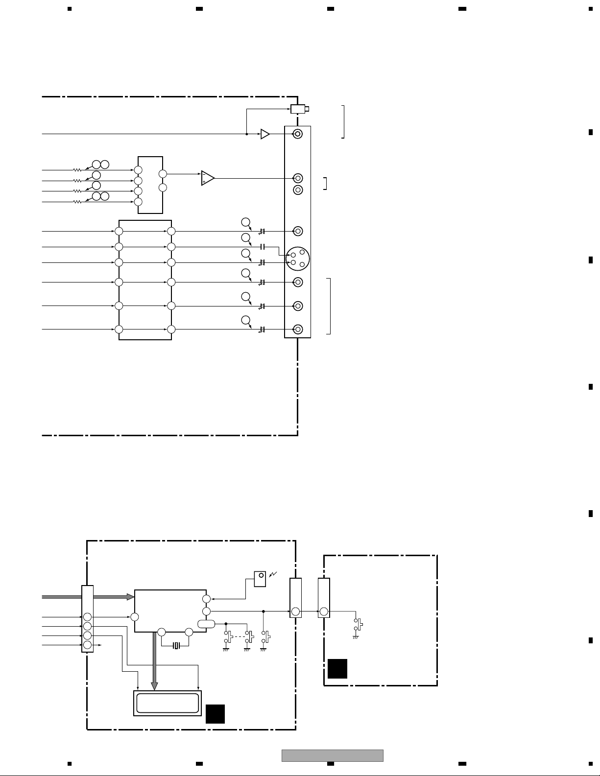
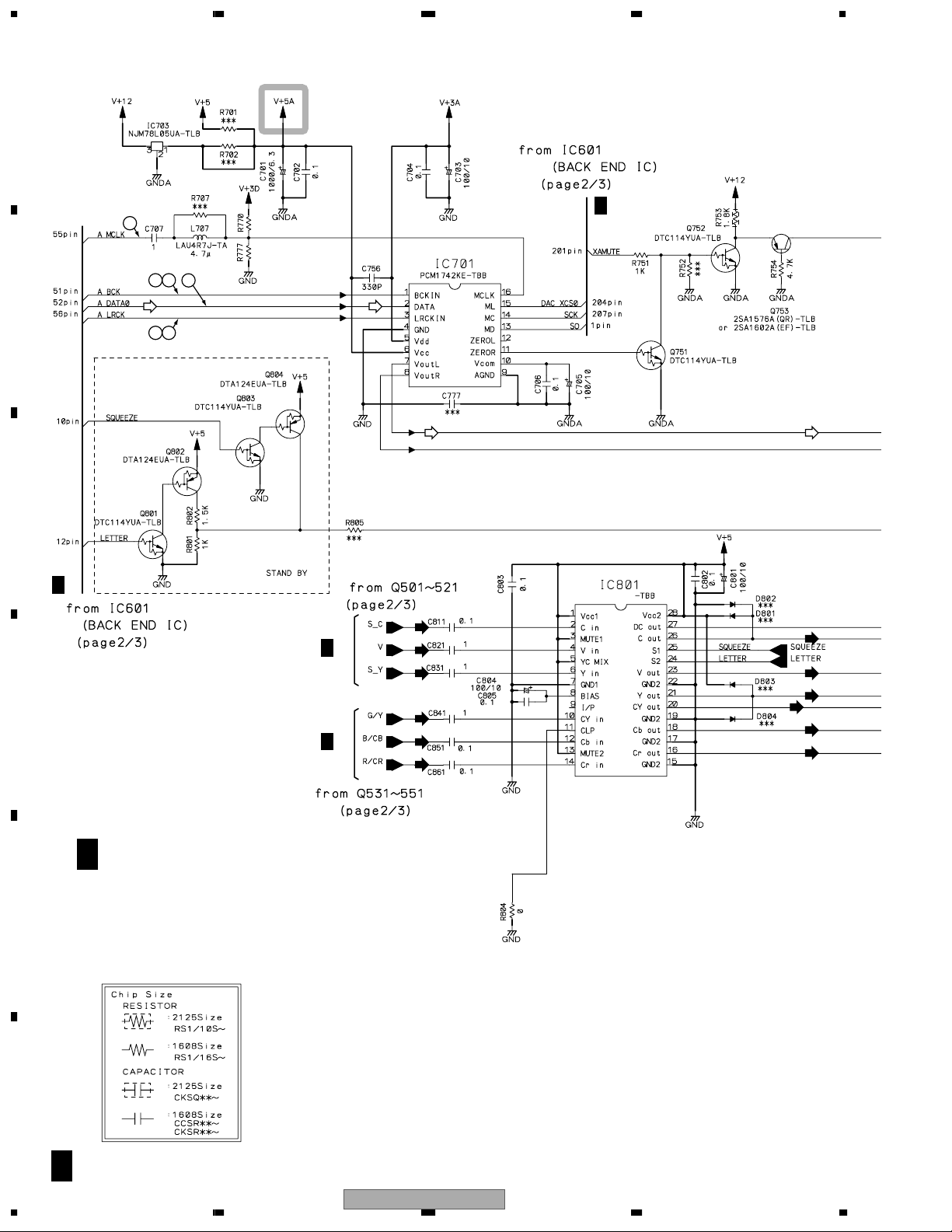
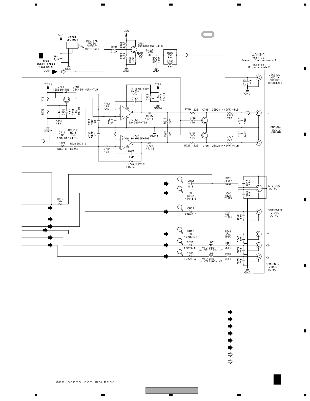
3.6 DVDM ASSY 3/3 [AUDIO/VIDEO BLOCK]
A
3
B
2/3
2.2K 1.5K
74
8
B
65
C
B
2/3
B
2/3
D
B
2/3
AUDIO DAC
S-C
V
S-Y
G/Y
B/Cb
R/Cr
MM1623AF
G/Y
S-C
V
S-Y
B/Cb
R/Cr
E
F
B 3/3
DVDM ASSY (VWS1555)
B 3/3
26
1234
VIDEO DRIVER
DV-363-S
5678
: The power supply is shown with
A
the marked box.
B
2/3
D
2.2K
2.7K
680K
R724
S-C
S-Y
D
B
C
14
13
G/Y
S-C
S-Y
B/Cb
R/Cr
10
11
12
9
D
3– !: Refer to "3.2 WAVEFORMS".
: V SIGNAL ROUTE
V
S-C
: S-VIDEO OUT C SIGNAL ROUTE
: S-VIDEO OUT Y SIGNAL ROUTE
S-Y
: R/Cr SIGNAL ROUTE
R/Cr
: G/Y SIGNAL ROUTE
G/Y
: B/Cb SIGNAL ROUTE
B/Cb
: AUDIO SIGNAL ROUTE
: AUDIO(DIGITAL) SIGNAL ROUTE
D
E
F
V
V
G/Y
B/Cb
R/Cr
56
DV-363-S
B 3/3
7
8
27
 Loading...