

Pioneer DV-353, DV-353-K, DV-353-S Service manual
OPEN/
CLOSE
0
Î
¡
1
¢
STANDBY/ON
4
DV-353-K
3
8
7
DVD PLAYER
DV-353-K
DV-353-S
DV-250
DV-251
THIS MANUAL IS APPLICABLE TO THE FOLLOWING MODEL(S) AND TYPE(S).
Model Power Requirement
DV-353-K AC120V 1
DV-353-K AC120V 1
DV-353-S AC120V 1
DV-250
DV-250
DV-251
KUXJ
KCXJ
KUXU/CA
KUXU
KCXU
KUXQ
Type
AC120V 1
AC120V
AC120V
Regional restriction
codes (Region No.)
1
1
ORDER NO.
RRV2592
Remarks
For details, refer to "Important symbols for good services".
PIONEER CORPORATION 4-1, Meguro 1-chome, Meguro-ku, Tokyo 153-8654, Japan
PIONEER ELECTRONICS (USA) INC. P.O. Box 1760, Long Beach, CA 90801-1760, U.S.A.
PIONEER EUROPE NV Haven 1087, Keetberglaan 1, 9120 Melsele, Belgium
PIONEER ELECTRONICS ASIACENTRE PTE. LTD. 253 Alexandra Road, #04-01, Singapore 159936
PIONEER CORPORATION 2002
T – ZZE APR. 2002 Printed in Japan
SAFETY INFORMATION
This service manual is intended for qualified service technicians; it is not meant for the casual
do-it-yourselfer. Qualified technicians have the necessary test equipment and tools, and have been
trained to properly and safely repair complex products such as those covered by this manual.
Improperly performed repairs can adversely affect the safety and reliability of the product and may
void the warranty. If you are not qualified to perform the repair of this product properly and safely, you
should not risk trying to do so and refer the repair to a qualified service technician.
WARNING
This product contains lead in solder and certain electrical parts contain chemicals which are known to the state of California to
cause cancer, birth defects or other reproductive harm.
Health & Safety Code Section 25249.6 – Proposition 65
NOTICE
(FOR CANADIAN MODEL ONLY)
Fuse symbols (fast operating fuse) and/or (slow operating fuse) on PCB indicate that replacement
parts must be of identical designation.
REMARQUE
(POUR MODÈLE CANADIEN SEULEMENT)
Les symboles de fusible (fusible de type rapide) et/ou (fusible de type lent) sur CCI indiquent que
les pièces de remplacement doivent avoir la même désignation.
(FOR USA MODEL ONLY)
1. SAFETY PRECAUTIONS
The following check should be performed for the
continued protection of the customer and service
technician.
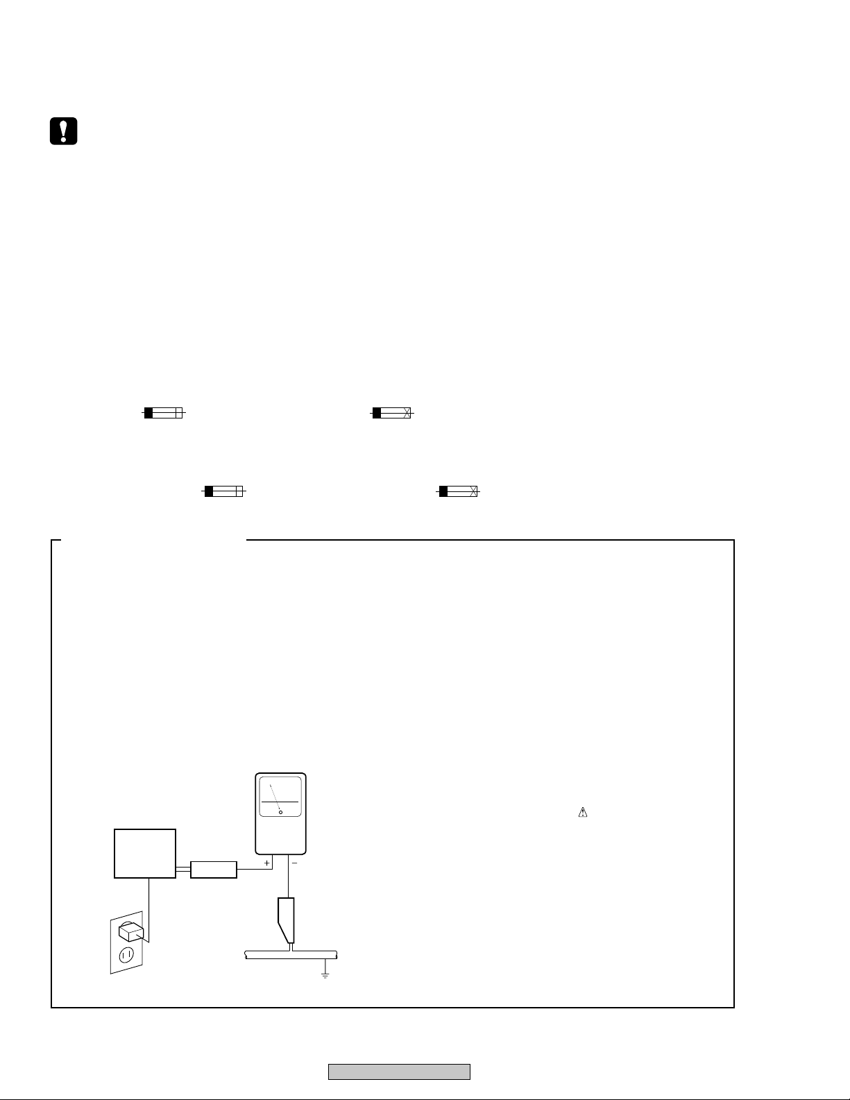
LEAKAGE CURRENT CHECK
Measure leakage current to a known earth ground
(water pipe, conduit, etc.) by connecting a leakage
current tester such as Simpson Model 229-2 or
equivalent between the earth ground and all exposed
metal parts of the appliance (input/output terminals,
screwheads, metal overlays, control shaft, etc.). Plug
the AC line cord of the appliance directly into a 120V
AC 60 Hz outlet and turn the AC power switch on. Any
current measured must not exceed 0.5 mA.
Reading should
not be above
0.5 mA
Earth
ground
Device
under
test
Also test with
plug reversed
(Using AC adapter
plug as required)
Test all
exposed metal
surfaces
AC Leakage Test
Leakage
current
tester
ANY MEASUREMENTS NOT WITHIN THE
LIMITS OUTLINED ABOVE ARE INDICATIVE
OF A POTENTIAL SHOCK HAZARD AND
MUST BE CORRECTED BEFORE RETURNING THE APPLIANCE TO THE CUSTOMER.
2. PRODUCT SAFETY NOTICE
Many electrical and mechanical parts in the appliance
have special safety related characteristics. These are
often not evident from visual inspection nor the
protection afforded by them necessarily can be obtained
by using replacement components rated for voltage,
wattage, etc. Replacement parts which have these
special safety characteristics are identified in this
Service Manual.
Electrical components having such features are
identified by marking with a
on the parts list in this Service Manual.
The use of a substitute replacement component which
does not have the same safety characteristics as the
PIONEER recommended replacement one, shown in the
parts list in this Service Manual, may create shock, fire,
or other hazards.
Product Safety is continuously under review and new
instructions are issued from time to time. For the latest
information, always consult the current PIONEER
Service Manual. A subscription to, or additional copies
of, PIONEER Service Manual may be obtained at a
nominal charge from PIONEER.
on the schematics and
2
DV-353-K
[ Important symbols for good services ]
In this manual, the symbols shown-below indicate that adjustments, settings or cleaning should be made securely.
When you find the procedures bearing any of the symbols, be sure to fulfill them:
1. Product safety
You should conform to the regulations governing the product (safety, radio and noise, and other regulations), and
should keep the safety during servicing by following the safety instructions described in this manual.
2. Adjustments
To keep the original performances of the product, optimum adjustments or specification confirmation is indispensable.
In accordance with the procedures or instructions described in this manual, adjustments should be performed.
3. Cleaning
For optical pickups, tape-deck heads, lenses and mirrors used in projection monitors, and other parts requiring cleaning,
proper cleaning should be performed to restore their performances.
4. Shipping mode and shipping screws
To protect the product from damages or failures that may be caused during transit, the shipping mode should be set or
the shipping screws should be installed before shipping out in accordance with this manual, if necessary.
5. Lubricants, glues, and replacement parts
Appropriately applying grease or glue can maintain the product performances. But improper lubrication or applying
glue may lead to failures or troubles in the product. By following the instructions in this manual, be sure to apply the
prescribed grease or glue to proper portions by the appropriate amount.For replacement parts or tools, the prescribed
ones should be used.
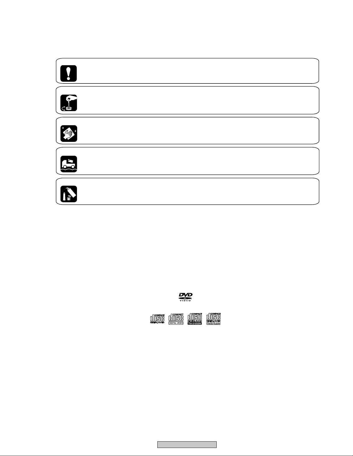
Discs compatible with this
player
Any disc that displays one of the following
logos should play in this player. Other
formats, including DVD-Audio, DVD-RAM,
DVD-ROM, CD-ROM (except those that
contain MP3 files), SACD and Photo CD will
not play.
Audio-CD
DVD-Video
Video-CD CD-R CD-RW
DV-353-K
3

CONTENTS
1. SPECIFICATIONS .................................................................................................................................................5
2. EXPLODED VIEWS AND PARTS LIST ............................................................................................................... 6
2.1 PACKING ........................................................................................................................................................6
2.2 EXTERIOR SECTION ..................................................................................................................................... 8
2.3 LOADING MECHANISM ASSY ................................................................................................................... 10
2.4 TRAVERSE MECHANISM ASSY-S ............................................................................................................ 14
3. BLOCK DIAGRAM AND SCHEMATIC DIAGRAM ............................................................................................ 16
3.1 BLOCK DIAGRAM ....................................................................................................................................... 16
3.1.1 SIGNAL ROUTE........................................................................................................................................ 16
3.1.2 POWER SUPPLY BLOCK ........................................................................................................................ 18
3.1.3 WAVEFORMS ........................................................................................................................................... 19
3.2 LOAB ASSY and OVERALL WIRING DIAGRAM ........................................................................................20
3.3 FJMB ASSY 1/5 [FRONT END BLOCK] ...................................................................................................... 22
3.4 FJMB ASSY 2/5 [BACK END BLOCK] ........................................................................................................ 24
3.5 FJMB ASSY 3/5 [AUDIO BLOCK] ............................................................................................................... 26
3.6 FJMB ASSY 4/5 [VIDEO BLOCK]................................................................................................................ 28
3.7 FJMB ASSY 5/5 [FL CONTROL BLOCK] .................................................................................................... 30
3.8 IRKY and PSWB ASSYS ............................................................................................................................. 32
3.9 POWER SUPPLY UNIT (VWR1351) ........................................................................................................... 34
3.10 POWER SUPPLY UNIT (VWR1353) ......................................................................................................... 35
4. PCB CONNECTION DIAGRAM ......................................................................................................................... 37
4.1 LOAB ASSY ................................................................................................................................................. 37
4.2 FJMB ASSY.................................................................................................................................................. 38
4.3 IRKY and PSWB ASSYS ............................................................................................................................. 42
4.4 POWER SUPPLY UNIT (VWR1351) ........................................................................................................... 43
4.5 POWER SUPPLY UNIT (VWR1353) ........................................................................................................... 44
5. PCB PARTS LIST ............................................................................................................................................... 45
6. ADJUSTMENT.................................................................................................................................................... 48
6.1 ADJUSTMENT ITEMS AND LOCATION ..................................................................................................... 48
6.2 JIGS AND MEASURING INSTRUMENTS................................................................................................... 48
6.3 NECESSARY ADJUSTMENT POINTS ....................................................................................................... 49
6.4 TEST MODE................................................................................................................................................. 50
6.5 MECHANISM ADJUSTMENT ...................................................................................................................... 51
7. GENERAL INFORMATION ................................................................................................................................ 54
7.1 DIAGNOSIS.................................................................................................................................................. 54
7.1.1 TEST MODE.............................................................................................................................................. 54
7.1.2 DISPLAY OF THE MECHANISM ERROR HISTORY .............................................................................. 60
7.1.3 TEST POINTS LOCATION & WAVEFORMS ........................................................................................... 64
7.1.4 TROUBLE SHOOTING ............................................................................................................................. 68
7.1.5 SEQUENCE AFTER THE POWER ON .................................................................................................... 70
7.1.6 DISASSEMBLY ......................................................................................................................................... 71
7.2 IC .................................................................................................................................................................. 76
7.3 CLEANING ................................................................................................................................................... 94
8. PANEL FACILITIES............................................................................................................................................ 95
4
DV-353-K
1. SPECIFICATIONS
General
System............................DVD-Video, Video CD,
CD and MP3 files
Power requirements..................AC 120 V, 60 Hz
Power consumption.....................................13 W
Power consumption (standby)
Weight.........................................2.4 kg (5lb 5oz)
Dimensions
DV-353.............420 (W) x 55 (H) x 278 (D) mm
9
/16 (W) x 2 3/16 (H) x 10 15/16 (D) in.)
(16
DV-250/251......420 (W) x 55 (H) x 276 (D) mm
9
/16 (W) x 2 3/16 (H) x 10 14/16 (D) in.)
(16
Operating temperature.................+5°C to +35°C
Operating humidity.............................5% to 85%
S-Video output
Y (luminance) - Output level...........1 Vp-p (75 Ω)
C (color) - Output level............286 mVp-p (75 Ω)
Jack.................................................S-Video jack
Video output
Output level....................................1 Vp-p (75 Ω)
Jack......................................................RCA jack
........................0.3 W
(+36°F to +96°F)
(no condensation)
Audio output (1 stereo pair)
Output level..........................During audio output
200 mVrms (1 kHz, –20 dB)
Number of channels...........................................2
Jacks.....................................................RCA jack
Digital audio characteristics
Frequency response....................4 Hz to 44 kHz
(DVD fs: 96 kHz)
S/N ratio...................................................118 dB
Dynamic range.........................................101 dB
Total harmonic distortion......................0.0016 %
Wow and flutter.................Limit of measurement
(0.001% W. PEAK) or lower
Digital output
Optical digital output...............Optical digital jack
Coaxial digital output............................RCA jack
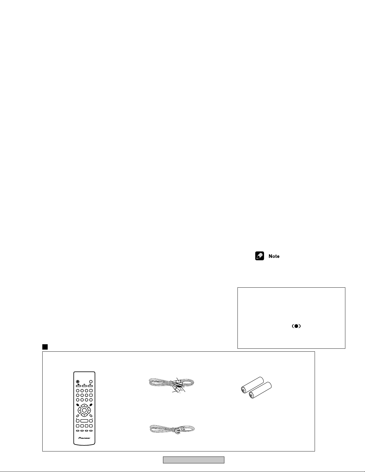
Accessories
Audio/video cable...............................................1
Power cable.......................................................
Remote control...................................................1
AA/R6P dry cell batteries...................................2
Operating Instructions........................................1
Warranty card.................................................... 1
1
B
Component Video output (Y, P
, PR)
Output level..............................Y: 1.0Vp-p (75 Ω)
B, PR: 0.7 Vp-p (75 Ω)
P
Jacks...................................................RCA jacks
Accessories
Remote Control : VXX2800
OPEN/CLOSE
STANDBY/ON
0
ANGLEAUDIO
SUBTITLE
CLEAR
23
1
ENTER
56
4
0
789
TOP MENU
MENU
ENTER
SETUP
RETURN
E/
/e
13
¡
8
4
7
¢
PLAY MODE SURROUND ZOOM DISPLAY
Audio/Video Cable (L=1.5m): XDE3049 AA/R6P Dry Cell Batteries
White
Yellow
Power Cable : ADG7022
Red
• The specifications and design of this
product are subject to change without
notice, due to improvement.
• Manufactured under license from Dolby
Laboratories. “Dolby” and the double-D
symbol are trademarks of Dolby Laboratories.
• “DTS” is a registered trademark of Digital
Theater Systems, Inc.
• TruSurround and the
trademarks of SRS Labs, Inc. TruSurround
technology is incorporated under license from
SRS Labs, Inc.
® symbol are
DV-353-K
5
2. EXPLODED VIEWS AND PARTS LIST
NOTES:
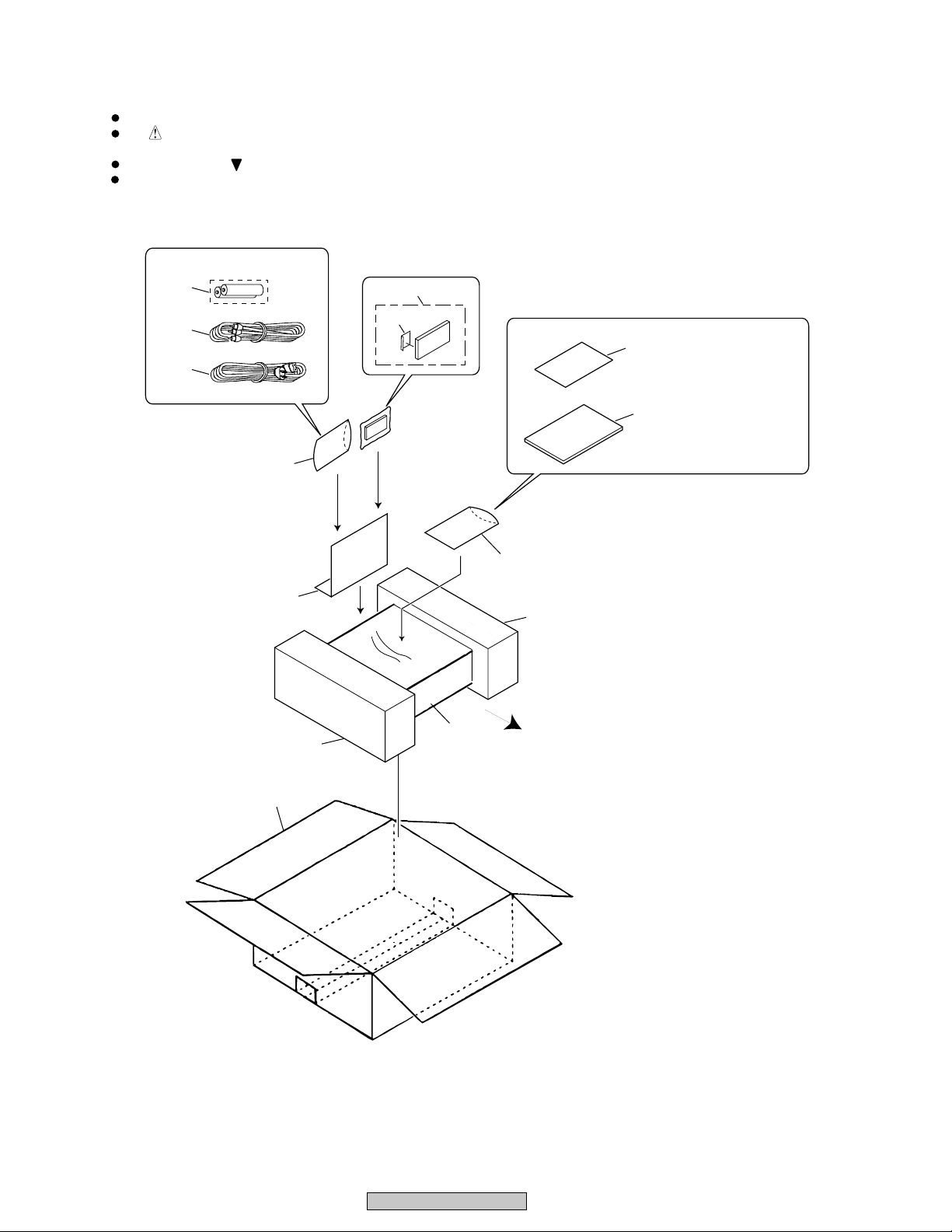
2.1 PACKING
Parts marked by "NSP" are generally unavailable because they are not in our Master Spare Parts List.
The mark found on some component parts indicates the importance of the safety factor of the part.
Therefore, when replacing, be sure to use parts of identical designation.
Screws adjacent to mark on product are used for disassembly.
For the applying amount of lubricants or glue, follow the instructions in this manual.
(In the case of no amount instructions, apply as you think it appropriate.)
3
8
1
4
11
9
7
14
2
5, 6
"Operating Instructions"
4
10
13
FRONT
12
6
DV-353-K
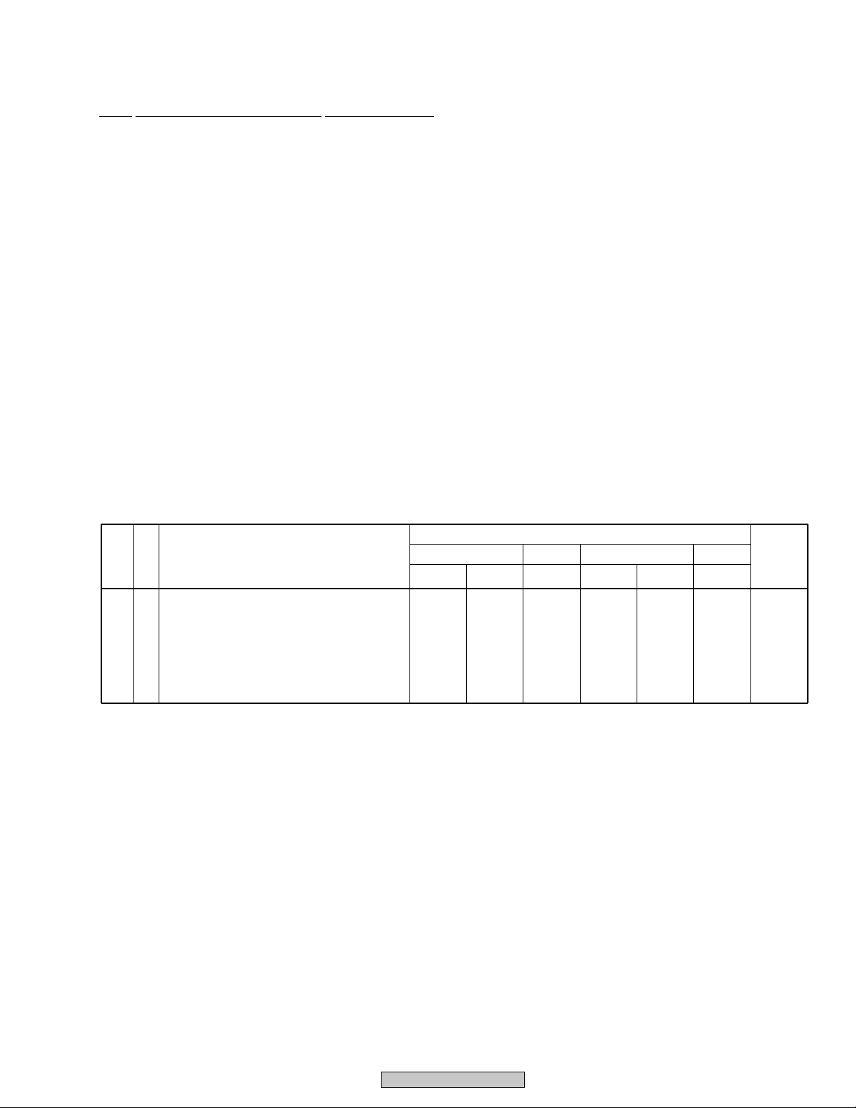
(1) PACKING PARTS LIST
(2) CONTRAST TABLE
Mark No. RemarksSymbol and Description
Part No.
DV-353-K DV-250 DV-251DV-353-S
KUXJ KCXJ KUXU/CA KUXU KCXU KUXQ
NSP
NSP23
6
9
10
11
12
Warranty Card
Dry Cell Battery (R6P, AA)
Operating Instructions (French)
Pad L
Pad R
Paper Board
Packing Case
ARY7057
VEM1031
Not used
VHA1295
VHA1296
VHC1088
VHG2237
ARY7045
VEM1031
VRC1147
VHA1295
VHA1296
VHC1088
VHG2187
ARY7057
VEM1010
Not used
VHA1297
VHA1298
VHC1089
VHG2169
ARY7057
VEM1030
Not used
VHA1297
VHA1298
VHC1089
VHG2158
ARY7045
VEM1030
VRC1147
VHA1297
VHA1298
VHC1089
VHG2160
ARY7057
VEM1030
Not used
VHA1297
VHA1298
VHC1089
VHG2197
DV-353-K/KUXJ, KCXJ, DV-353-S/KUXU/CA, DV-250/KUXU, KCXU and DV-251/KUXQ are constructed the same except for
the following :
Mark No. Description Part No.
> 1 Power Cable ADG7022
NSP 2 Warranty Card See Contrast table (2)
NSP 3 AA/R6P Dry Cell Battery See Contrast table (2)
4 Polyethylene Bag VHL1051
5 Operating Instructions VRB1285
(English)
6 Operating Instructions See Contrast table (2)
(French)
7 Remote Control VXX2800
8 Audio/Video Cable (L=1.5m) XDE3049
9 Pad L See Contrast table (2)
10 Pad R See Contrast table (2)
11 Paper Board See Contrast table (2)
12 Packing Case See Contrast table (2)
13 Seat Z23-007
14 Battery Cover VNK4997
DV-353-K
7
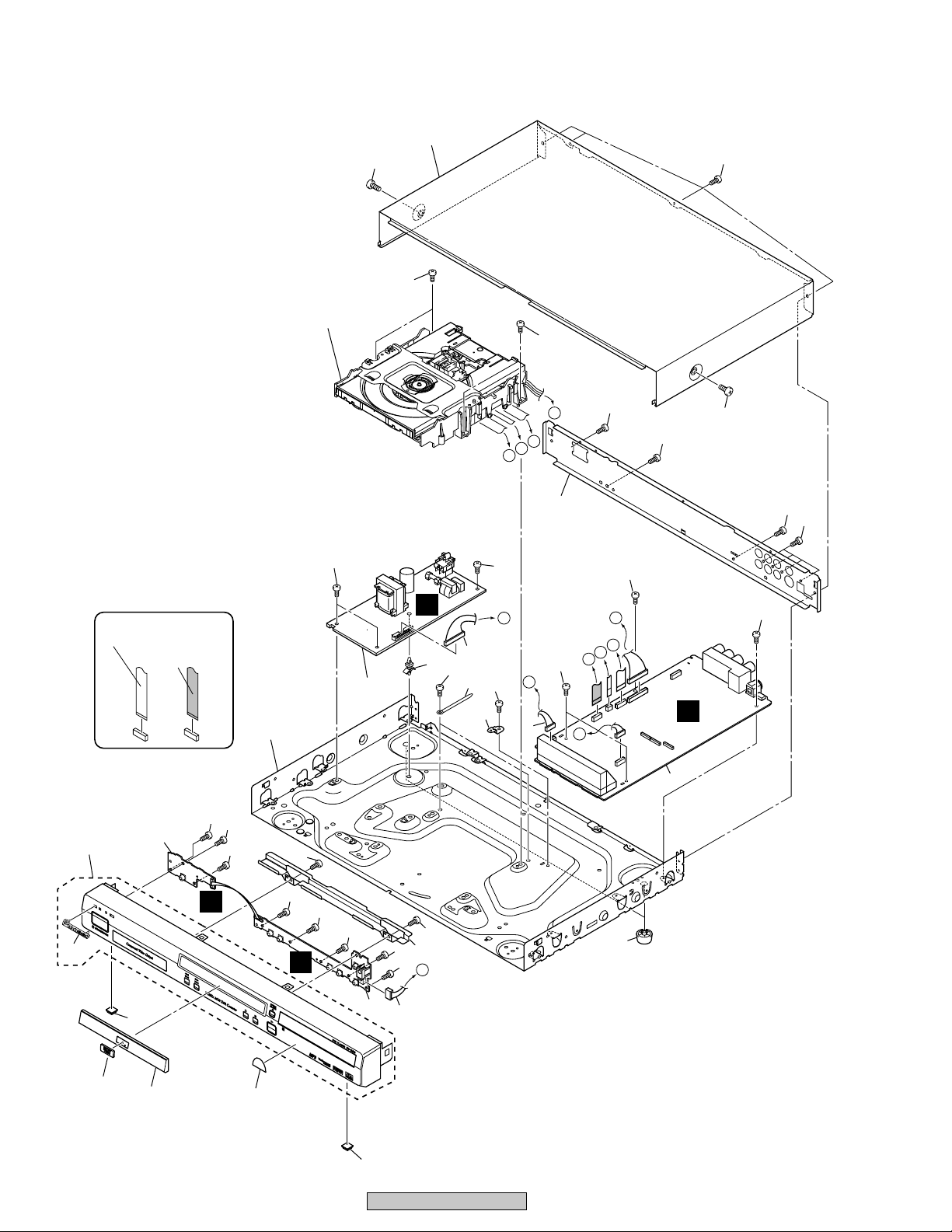
2.2 EXTERIOR SECTION
25
26
23
Refer to
"2.3 LOADING MECHANISM ASSY".
NON-CONTACT
SIDE
CONTACT
SIDE
12
23
8
23
23
23
22
B
E
D
C
25
22
23
23
B
A
22
F
E
D
C
13
22
E
11
22
7
10
B
5
22
14
22
F
6
3
24
D
24
24
21
24
24
C
24
24
16
1
24
17
24
24
A
4
DV-353-K
9
19
20
15
2
16
18
8
(1) EXTERIOR PARTS LIST
Mark No. Description Part No.
NSP 1 IRKY Assy VWG2344
NSP 2 PWSB Assy VWG2345
3 FJMB Assy VWS1515
4 Connector Assy PF05PP-Q12
5 Connector Assy PF13PP-D25
6 Connector Assy PG05KK-E37
> 7 POWER SUPPLY Unit VWR1351
(or VWR1353)
NSP 8 Loading Mechanism Assy See Cotrast table (2)
9 Leg Assy SX AEC7113
10 Cord Clamper RNH-184
11 Pcb Support VEC2184
NSP 12 Base Chassis See Cotrast table (2)
13 Rear Panel See Cotrast table (2)
14 PCB Base See Cotrast table (2)
15 DVD V Plate VAM1121
16 Rubber Foot VEB1325
17 FP Angle See Cotrast table (2)
18 Tray Panel See Cotrast table (2)
19 Front Panel Assy See Cotrast table (2)
20 Pioneer Badge See Cotrast table (2)
NSP 21 Energy Star Label AAX7876
22 Screw BBZ30P060FMC
23 Screw BBZ30P080FZK
24 Screw BBZ30P100FZK
25 Screw See Cotrast table (2)
26 Bonnet Case S See Cotrast table (2)
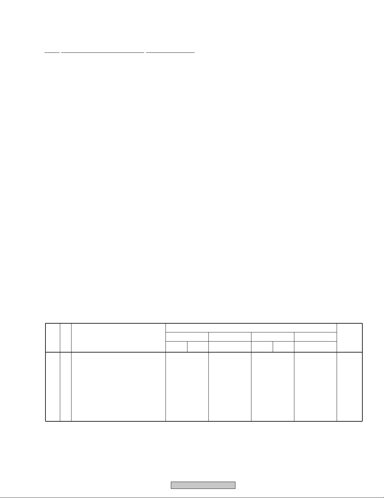
(2) CONTRAST TABLE
DV-353-K/KUXJ, KCXJ, DV-353-S/KUXU/CA, DV-250/KUXU, KCXU and DV-251/KUXQ are constructed the same except for
the following :
Part No.
Mark No. RemarksSymbol and Description
NSP
NSP812
Loading Mechanism Assy
Base Chassis
13
Rear Panel
14
PCB Base
17
FP Angle
18
Tray Panel
19
Front Panel Assy
20
Pioneer Badge
25
Screw
26
Bonnet Case S
DV-353-K DV-250 DV-251DV-353-S
KUXU/CA
VWT1196
VNA2409
VNA2421
VNE2277
VNE2267
VNK4952
VXA2486
XAM3006
BCZ40P060FZK
VXX2821
VWT1197
VNA2410
VNA2437
VNE2278
VNE2270
VNK4973
VXA2496
VAM1129
BCZ40P060FNI
VXX2823
KUXU KCXUKUXJ KCXJ
VWT1197
VNA2410
VNA2435
VNE2278
VNE2270
VNK4959
VXA2490
VAM1129
BCZ40P060FZK
VXX2830
KUXQ
VWT1188
VNA2410
VNA2436
VNE2278
VNE2270
VNK4962
VXA2491
VAM1130
BCZ40P060FZK
VXX2831
DV-353-K
9
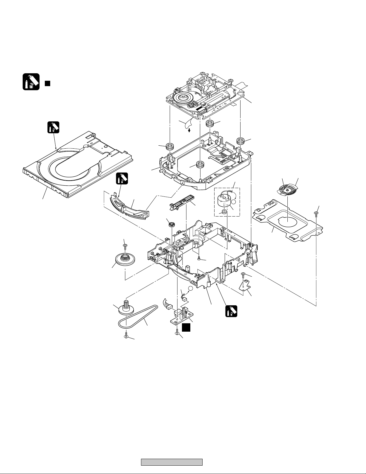
2.3 LOADING MECHANISM ASSY
Note :
Refer to
" Application of Lubricant".
Daifree
GEM1036
2
Refer to
"2.4 TRAVERSE MECHANISM
6
To FJMB
CN251
8
8
ASSY-S".
8
23
15
14
12
Lubricating Oil
GYA1001
13
22
9
22 22
16
8
20
3
17
21
7
A
11
1
A
A
4
5
22
10
Lubricating Oil
GYA1001
18
22
19
10
DV-353-K
(1) LOADING MECHANISM ASSY PARTS LIST
Mark No. Symbol and Description
Part No.
Remarks
VWT1196 VWT1197 VWT1188
NSP 16LOAB Assy
Flexible Cable (26P)
VWG2346
VDA1864
VWG2279
VDA1865
(2) CONTRAST TABLE
VWT1196, VWT1197 and VWT1188 are constructed the same except for the following :
Mark No. Description Part No.
NSP 1 LOAB Assy See Contrast table (2)
2 Traverse Mechanism Assy-S VXX2782
3 Loading Motor Assy VXX2505
4 Motor Pulley PNW1634
5 Carriage DC Motor / 0.3W PXM1027
6 Flexible Cable (26P) See Contrast table (2)
7 Connector Assy 2P VKP2253
8 Float Rubber VEB1327
9 Belt VEB1330
10 Stabilizer VNE2253
11 Loading Base VNL1917
12 Float Base DVD VNL1918
13 Drive Cam VNL1919
14 Gear Pulley VNL1921
15 Loading Gear VNL1922
16 Drive Gear VNL1923
17 SW Lever VNL1925
18 Clamper Plate VNE2251
19 Bridge VNE2252
20 Clamper VNL1924
21 Screw JGZ17P028FMC
22 Screw Z39-019
23 Tray VNL1920
DV-353-K
11
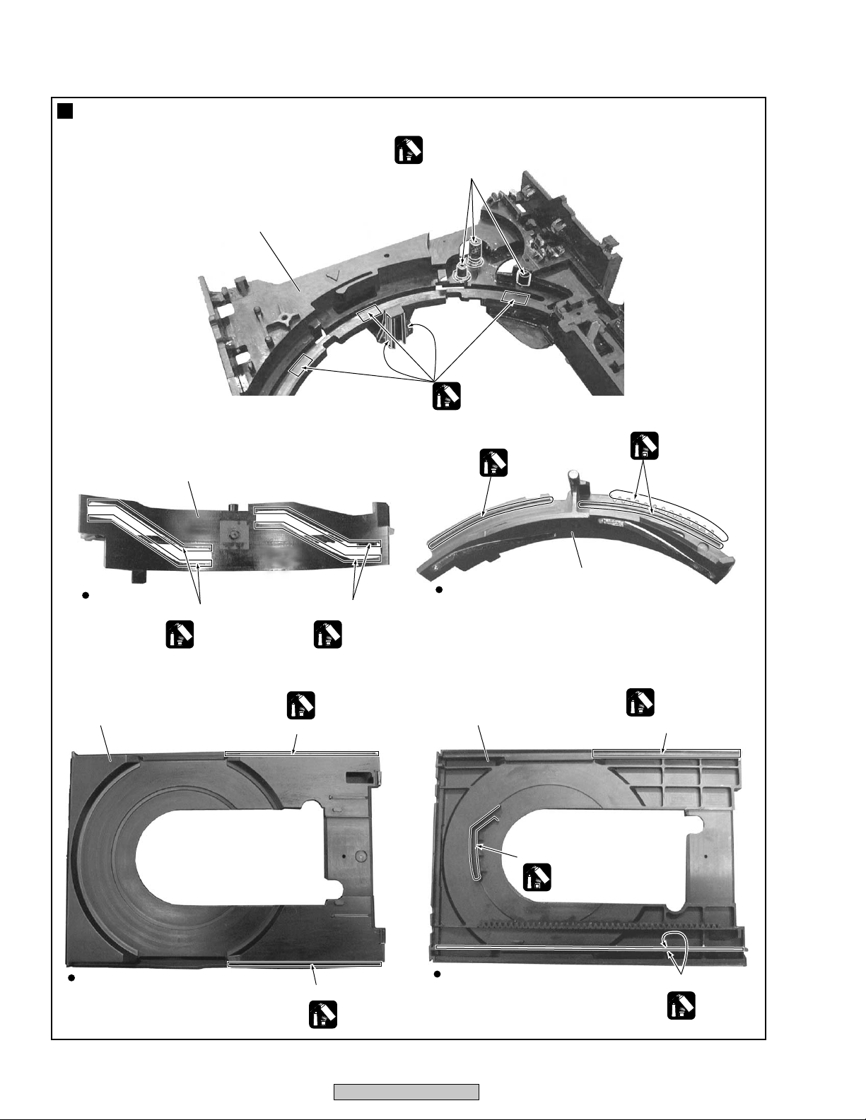
Application of Lubricant
No. 11
Loading Base
No. 13
Drive Cam
Lubricating Oil
GYA1001
Around the shaft
Lubricating Oil
GYA1001
Lubricating Oil
GYA1001
Lubricating Oil
GYA1001
Rear View
No. 23
Tray
Top View
Inner side of a ditch
Lubricating Oil
GYA1001
Inner side of a ditch
Lubricating Oil
GYA1001
Daifree
GEM1036
Concave of unevenness
Concave of unevenness
Daifree
GEM1036
Top View
No. 23
Tray
Bottom View
No. 13
Drive Cam
Daifree
GEM1036
Concave of unevenness
Inner side of a ditch
Daifree
GEM1036
Side of the rib
Daifree
GEM1036
12
DV-353-K

DV-353-K
13
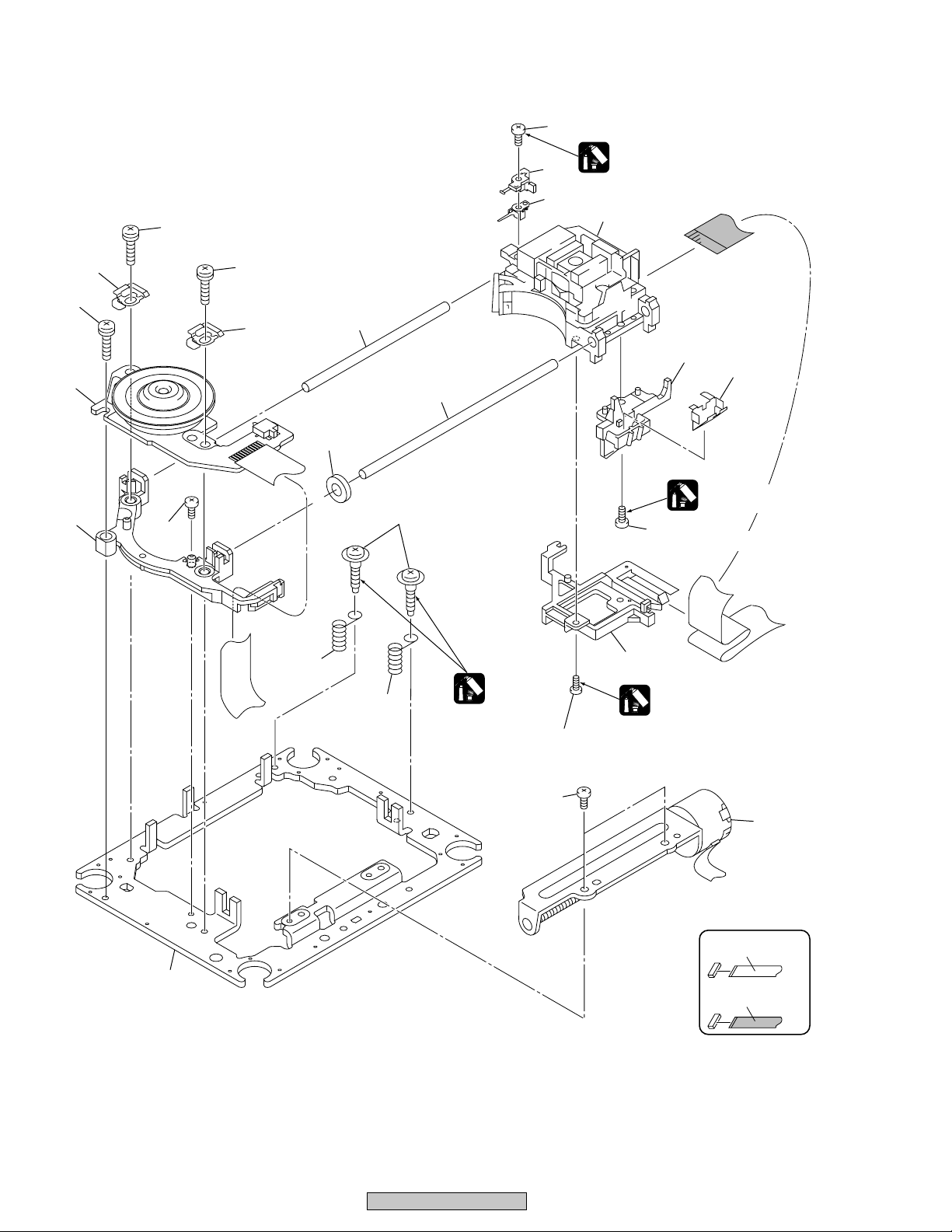
2.4 TRAVERSE MECHANISM ASSY-S
18
17 (Torque : 0.12 ± 0.01 N•m)
Silicone Adhesive
12
8
GEM1037
3
13
18
10
1
16
18
10
7
14
6
19
4 (Adjustment Screw)
5
Screw Tight
5
GYL1001
17 (Torque : 0.12 ± 0.01 N•m)
17
(Torque : 0.12 ± 0.01 N•m)
15
Silicone Adhesive
GEM1037
9
Silicone Adhesive
GEM1037
14
16
2
NON-CONTACT
SIDE
11
CONTACT SIDE
DV-353-K

TRAVERSE MECHANISM ASSY-S PARTS LIST
•
Mark No. Description Part No.
1 Spindle Motor VXM1088
(or VXM1089)
2 Stepping Motor VXM1090
(or VXM1091)
3 Pickup Assy-S OXX8003
4 Skew Screw VBA1080
5 Skew Spring VBH1335
6 Guide Bar VLL1514
7 Sub Guide Bar VLL1515
8 Hold Spring VNC1017
9 Joint Spring VNC1019
10 Support Spring VNC1020
NSP 11 Mechanism Chassis VNE2248
12 Slider VNL1811
13 Spacer VNL1913
14 Joint VNL1914
15 FFC Holder VNL1915
16 Screw BBZ20P050FZK
17 Tapping Screw OBA8009
18 Screw PMA26P100FMC
19 Damper Sheet VEB1335
DV-353-K
15
1
23
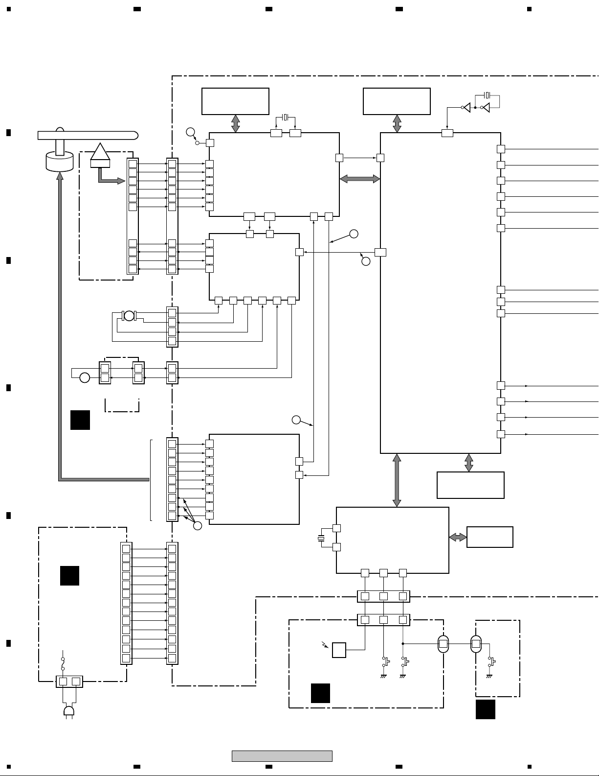
3. BLOCK DIAGRAM AND SCHEMATIC DIAGRAM
3.1 BLOCK DIAGRAM
A
3.1.1 SIGNAL ROUTE
Spindle
Motor
B
C
PICKUP
ASSY
20
21
15
16
19
17
24
25
26
23
Stepping
Motor
(Carriage)
M
(26P)
B1
B2
B3
B4
A
C
T_RTN
T_DRV
F_RTN
F_DRV
ST1ST1+
ST2+
ST2-
Work RAM for Error Correction
IC302
K6T1008V2E-TB70
1M SRAM
1
RF(TP)
CN151
7
6
12
11
8
10
3
2
1
4
CN3
4
3
2
1
(26P)
(4P)
3
RFSACD
L6315ATXXT
A
10
FRONT END IC
B
12
18
16
25
24
13
12
10
• RF Demodulation
C
• Servo Control
D
• Servo Decode
E
• Error Correction
F
FACT
123
3 20
IN3-
IC351
M56788AFP
FTS Driver
Focus, Tracking,
Stepper and
Loading Drive
VM1-35VM2-31VM2+32VM5-15VM5+
34
9
VM4VM4+
VM3+
VM3-
VM1+
IC301
FDO
X301
20MHz
131
TACT
124
IN4-
132
OUT_DATA(0) S_DATA
TDO
IN5-
17
14
FREOUT FREIN
PC(2) PC(6)
4238
SPDL
FG
Work RAM for MPEG Decode
K4S641632F-TC75
64M SDRAM
FE_DATA
84
PDM
LOAD_DRV
16
16
116
15
IC604
120
PIXCLK
HSYNC
_PWM0
IC601
STI5519AVB-B0C
BACK END IC
• System Control
• MPEG Video Decode
• Video Encode
• Video DAC
• Audio Decode
(MP3, Dolby)
• Sub-picture Decode
4
X601
27MHz
3562
IC605 TC7WU04FU
B_OUT
25
G_OUT
26
R_OUT
27
Y_OUT
32
C_OUT
33
CV_OUT
34
PIO381
PIO382
SPDIF
57
SQUEEZ
7
LETTER
8
DOUT
LOD-
-28V
GND
GND
GND
GND
LOD+
H1+
1
2
CN52
CN251
9
8
7
6
5
4
10
11
12
CN401
1
2
3
4
5
6
7
8
9
10
11
12
13
(5P)
(12P)
(13P)
17
H1+
9
H1-H1-
10
H2+H2+
11
H2-H2-
12
H3+H3+
13
H3-H3-
14
A1A1
7
A2A2
4
A3A3
2
IC251
BA6664FM
Spindle
Driver
• Spindle Drive
• FG Detection
2
24
FG
EC
22
5MHz
REMOTE
RECEIVER
UNIT
FG
SPDL PDM
X11
SPS-444L-H
C
IC11 PE5314A
3
4
IC301
FL CONTROL
X1
MICROCOMPUTER
• Main Unit Key Input
X2
• Remote Control Receive
• FL Display Control
KEY1
IR
17
21
5 2 1
IR
KEY1
5 2 1
IRKY ASSY
KEY0
22
CN11
KEY0
(5P)
CN301
(5P)
DAC_SCLK
PCMDATA0
PCKCLK
LRCLK
IC603
VYW1890
8M FLASH ROM
V11
FL TUBE
KEY3
1 1
J301
(3P)
D
PSWB ASSY
A_BCK
51
A_DATA0
52
A_MCLK
55
A_LRCK
56
1
+–
2
M
Loading
CN602
Motor
(2P)
Assy
LOAB ASSY
A
1
2
CN601
(5P)
D
VWR1351: CN101
VWR1353: CN2
E
E
POWER
SUPPLY
UNIT
F1
CN1
(2P)
1 2
LIVE
NEUTRAL
(13P)
1
2
3
4
5
6
7
8
9
10
11
12
13
EV+6V(B)
EV+6V(A)
FLDC+
FLDC-
P-CONT
SW+12V
EV+4V
SW+3.3V
F
AC IN
16
1234
DV-353-K
5
678
A
Q607
Q606
Q605
Q604
Q603
Q602
B/CB
R/CR
S_C
Q807,Q808
Q805,Q806
R721
R722
R723
G/Y
S_Y
V
4 7
8
3
5 6
FJMB ASSY
B
Cb IN
14
CY IN
12
16
6
2
4
Cr IN
Y IN
C IN
V IN
1
2
16
3
BCKIN
DATA
MCLK
LRCKIN
MM1567AJ
6 IN • 6 OUT
VIDEO AMP
• VIDEO
• LPF
• AMP
• Driver
YOUT b
IC801
Audio 2ch DAC
YOUT a
COUT
VOUT b
VOUT a
CYOUT b
CYOUT a
CrOUT b
CrOUT a
CbOUT b
CbOUT a
IC711
PCM1742KE
28
27
33
31
30
25
24
19
18
22
21
Vout L
Vout R
Y
C
V
G/Y
R/Cr
B/Cr
7
8
LOUT
ROUT
1– $: Refer to "3.1.3 WAVEFORMS".
13
C832
14
C822
9
C812
10
C842
12
C862
11
C852
AUDIO LPF
BA4560F
IC731-1/2
2
3
IC731-2/2
5
6
1
7
Q941
Y
C
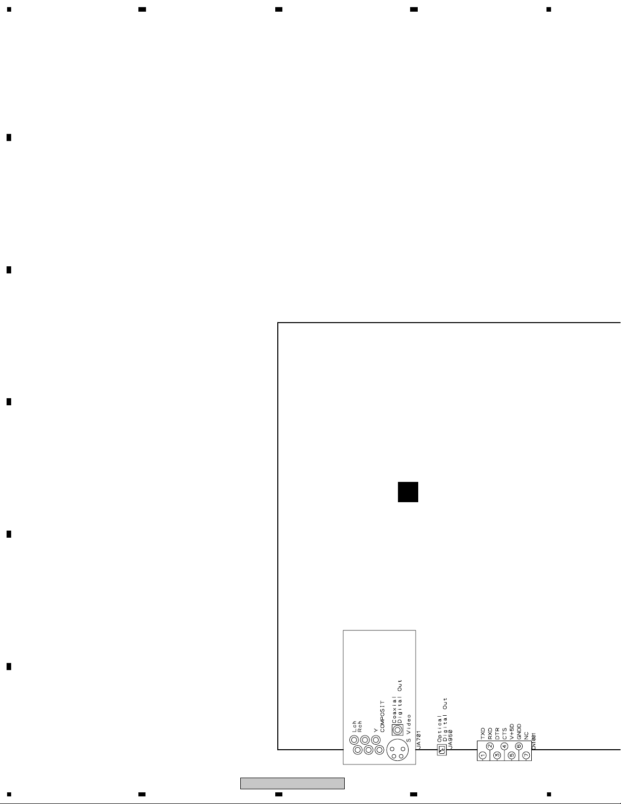
JA950
S VIDEO
COMPOSITE
VIDEO OUT
Y
COMPONENT
Cr
VIDEO OUT
Cb
OPTICAL
COAXIAL
L
AUDIO
OUT
R
DIGITAL
OUT
B
C
D
E
F
DV-353-K
5
6
7
8
17
1
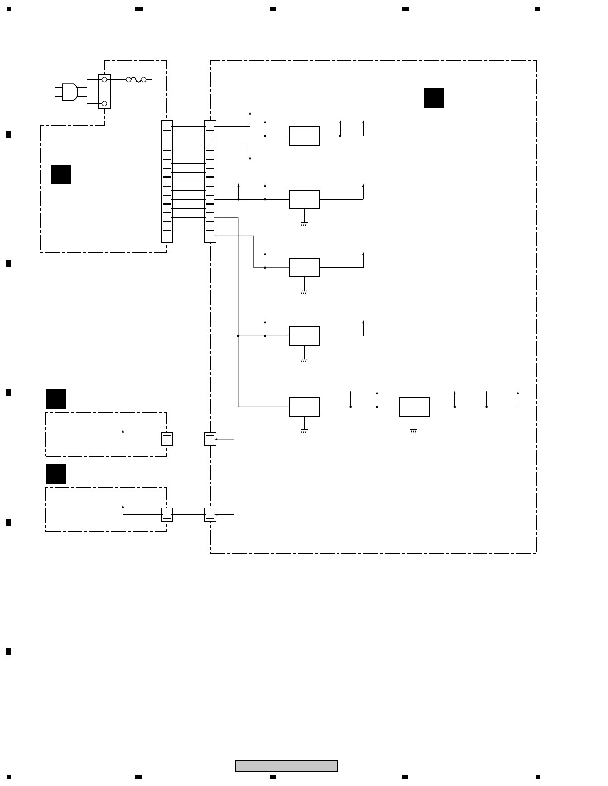
3.1.2 POWER SUPPLY BLOCK
23
4
A
AC IN
B
POWER SUPPLY
ASSY
E
LIVE
NEUTRAL
F1
VWR1351: CN101
VWR1353: CN2
(13P)
1
2
3
4
5
6
7
8
9
10
11
12
13
EV+6V (B)
EV+6V (A)
-28V
FLDC+
FLDC-
GND
P-CONT
GND
SW+12V
GND
EV+4V
GND
SW+3.3V
CN401
1
2
3
4
5
6
7
8
9
10
11
12
13
(13P)
V+6B
V+6A
-28V
V+12M V+5AV+12D
IC421
MM1565AF
+5V Reg.
V+5S V+5V
IC901
NJM78L05A
+5V Reg.
31
2
IC431
PQ025EZ01ZP
V+3D V+2R5
+2.5V Reg.
IN OUT
FJMB ASSY
B
IC451
MM1385EN
V+4E
C
+3V Reg.
IN OUT
V+3E
IC303
BA18BC0FP
+1.8V Reg.
13
2
LOAB ASSY
A
V+3D
CN601
(5P)
4 4
CN52
(5P)
V+3R5D
IC441
PQ070XZ02ZP
+3.5V Reg.
VIN VOUT
V+3R5D V+3R5A V+1RBD V+1RBA1 V+1RBA2
D
IRKY ASSY
C
V+3E
CN301
(5P)
3 3
CN11
(5P)
V+3E
E
F
18
DV-353-K
1234
5
678
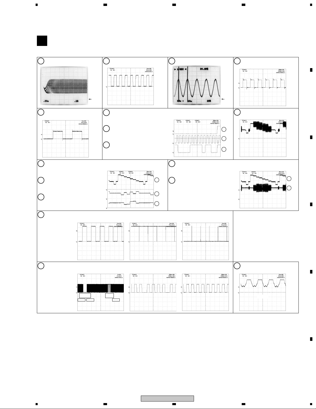
3.1.3 WAVEFORMS
Note : The encircled numbers denote measuring point in the schematic diagram.
FJMB ASSY
B
Measurement condition
No. 3 to 8 : reference A1 (DVD), T2-chp 1
IC301 - pin 3 [RF]
1
V: 200mV/div. H: 0.1µsec/div.
: No. 1 to 2 and 9 to 14 : reference A1 (DVD), T2-chp 19, Color-bar
IC251 - pin 24 [FG]
2
V: 1V/div. H: 5msec/div.
IC711 - pin 16 [AUDIO DAC -MCK]
34
V: 1V/div. H: 20nsec/div.
Foot of R721 (IC711 - pin 1)
[AUDIO DAC -BCK]
V: 2V/div. H: 200nsec/div.
A
Foot of R723 (IC711 - pin 3)
5
[AUDIO DAC -LRCK]
V: 2V/div. H: 5µsec/div.
Foot of C842 (IC801 - pin 24, 25)
10
[Component Video output -Y]
V: 1V/div. H: 10µsec/div.
Foot of C852 (IC801 - pin 18, 19)
11
[Component Video output -Pb]
V: 2V/div. H: 10µsec/div.
Foot of C862 (IC801 - pin 21, 22)
12
[Component Video output -Pr]
V: 2V/div. H: 10µsec/div.
IC601 - pin 116 [LOAD_DRV]
15
V: 1V/div. H: 5µsec/div.
GND
Foot of R723 (IC711 - pin 3)
6
[AUDIO DAC -LRCK]
V: 2V/div. H: 500nsec/div.
Foot of R721 (IC711 - pin 1)
7
[AUDIO DAC -BCK]
V: 2V/div. H: 500nsec/div.
Foot of R722 (IC711 - pin 2)
8
[AUDIO DAC -DATA]
V: 2V/div. H: 500nsec/div.
Foot of C832 (IC801 - pin 27, 28)
13
[S Video output -Y]
V: 1V/div. H: 10µsec/div.
10
11
12
[Tray stops] [Tray is opening] [Tray is closing]
Foot of C822 (IC801 - pin 33)
14
[S Video output -C]
V: 1V/div. H: 10µsec/div.
6
7
8
GND
Foot of C812 (IC801 - pin 30, 31)
9
[Composite Video output]
V: 1V/div. H: 10µsec/div.
B
C
13
14
D
IC301 - pin 42 [SPDL_PDM]
16
[STOP→PLAY→STOP] [STOP]
Accelertar
ON
STOP STOPPLAY
Brakes
ON
[PLAY]
V: 2V/div. H: 500nsec/div. V: 2V/div. H: 500nsec/div. V: 2V/div. H: 2msec/div.V: 2V/div. H: 1sec/div.
DV-353-K
5
6
CN251 - pin 12, 11, 10
17
(IC251 - pin 2, 4, 7)
[Spidle driver -A3, A2, A1]
[PLAY]
E
F
19
7
8
1
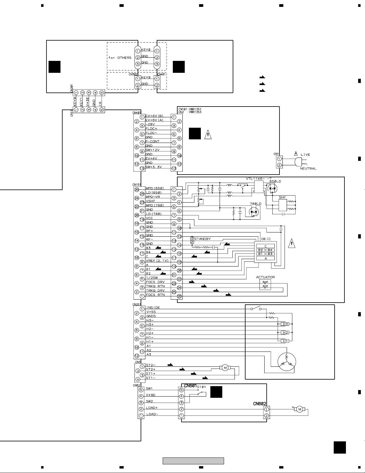
3.2 LOAB ASSY and OVERALL WIRING DIAGRAM
A
B
23
4
C
D
FJMB ASSY
B
(VWS1515)
E
PB
F
PR
ABCDE
20
1234
DV-353-K
5
Note : When ordering service parts, be sure to refer to "EXPLODED VIEWS and PARTS LIST" or "PCB PARTS LIST"
678
A
IRKY ASSY
C
(VWG2344)
for ##XCN type
PSWB ASSY
D
(VWG2345)
H
POWER SUPPLY UNIT
(VWR1351 or VWR1353)
(F)
: FOCUS SERVO LOOP LINE
(T)
: TRACKING SERVO LOOP LINE
(S)
: SLIDER SERVO LOOP LINE
B
C
(F)
(F)
(T)
(F)
(F)
(F)
(S)
(S)
(S)
(F)
(T)
(F)
(F)
(T)
(T)
STEPPING MOTOR
: VXM1090
(S)
(F)
(F)
LOAB ASSY
A
(VWG2279)
PICKUP ASSY-S
(OXX8003)
SPINDLE
MOTOR
: VXX1088
LOADING
MOTOR ASSY
: VXX2505
D
E
F
CDAB A
DV-353-K
5
6
7
8
21
1
23
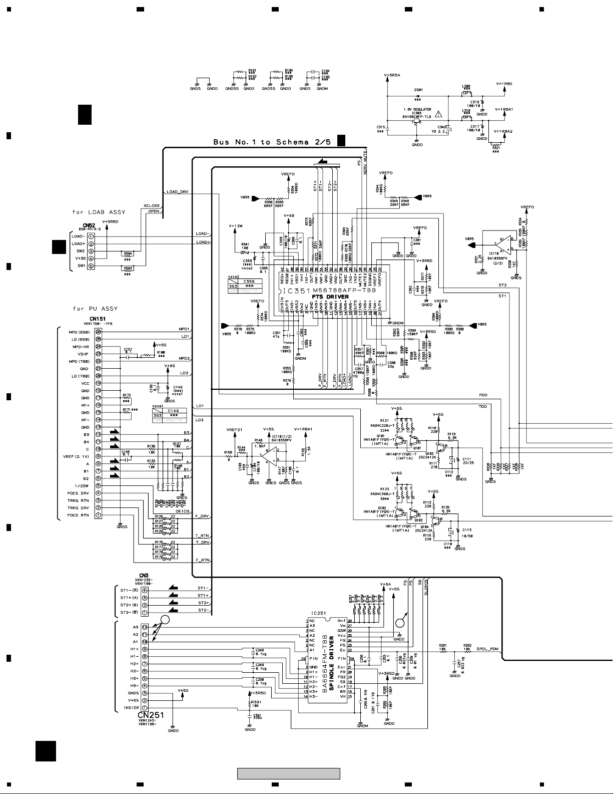
3.3 FJMB ASSY 1/5 [FRONT END BLOCK]
A
4
B 1/5
B
FJMB ASSY (VWS1515)
B
2/5
(S)
A
CN601
C
(F)
(F)
PICKUP ASSY
D
E
STEPPING
(T)
(T)
(F)
(F)
MOTOR
17
(S)
(S)
(S)
(S)
2
SPINDLE
MOTOR
F
1/5
B
22
1234
DV-353-K
5
B
2/5
678
A
B
1, 2, #, $: Refer to "3.1.3 WAVEFORMS".
(F)
: FOCUS SERVO LOOP LINE
(T)
: TRACKING SERVO LOOP LINE
(S)
: SLIDER SERVO LOOP LINE
VCC33DAC
C
D
1
VCC18MN
16
E
(F)
(F)
(F)
(F)
(T)
(T)
F
1/5
B
DV-353-K
5
6
7
8
23
1
23
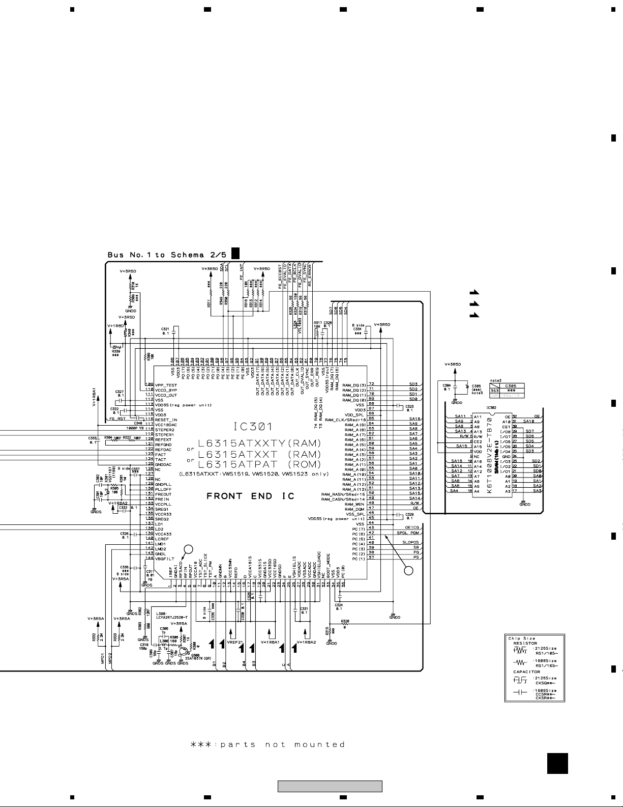
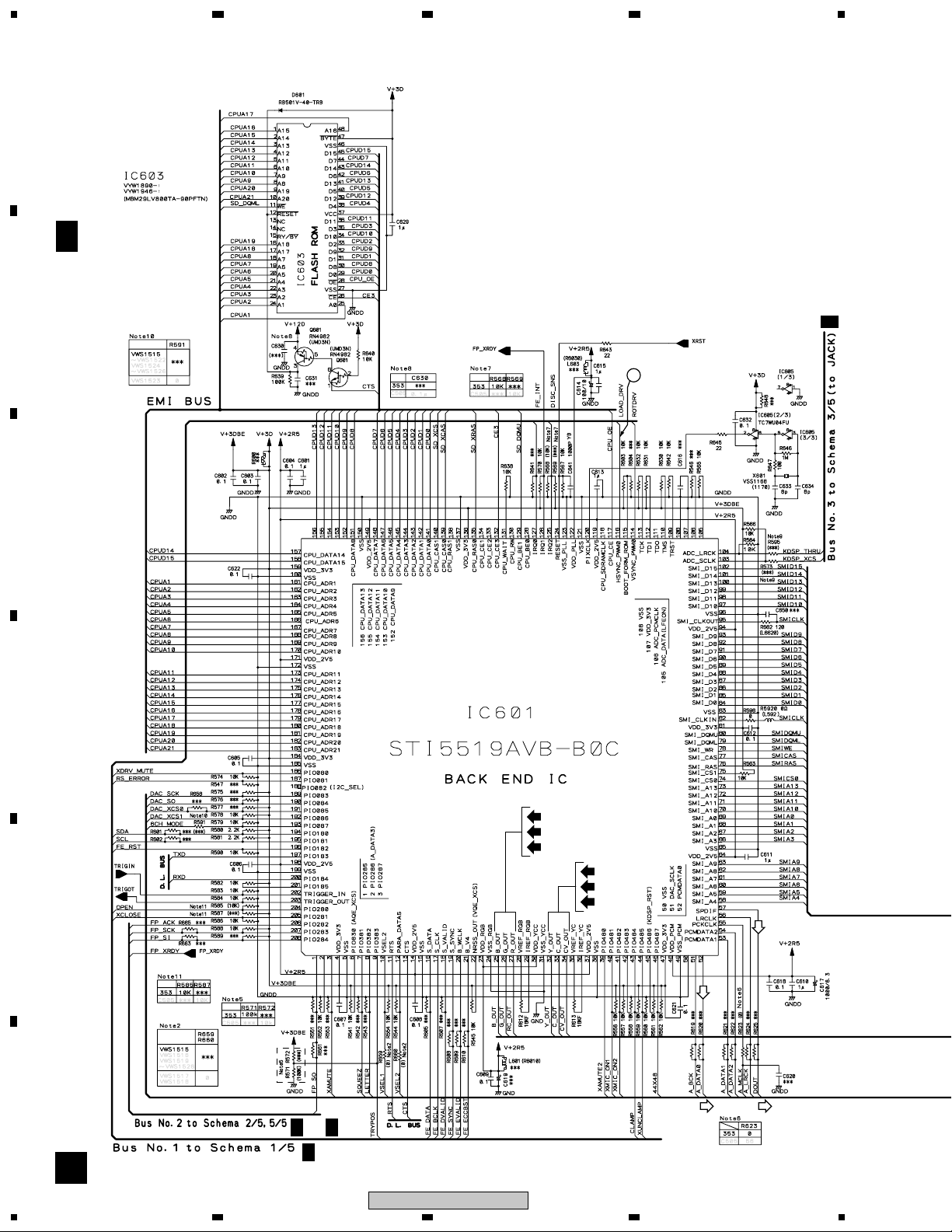
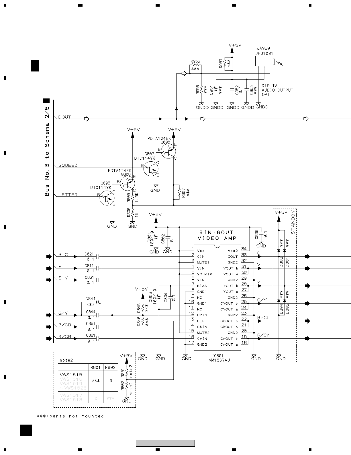
3.4 FJMB ASSY 2/5 [BACK END BLOCK]
A
4
FJMB ASSY
(8M)
B 2/5
B
C
(VWS1515)
3/5
B
15
D
(B/Cb)
(G/Y)
(R/Cr)
(S_Y)
(S_C)
(V)
E
F
2/5
B
24
1234
B
2/5B5/5
B
1/5
DV-353-K
(D)
(D)
5
678
A
5/5
B
2/5
B
B
E
VWR1351: CN101
VWR1353: CN2
: The power supply is shown with the marked box.
(V)
(S_C)
(S_Y)
4/5
B
3/5
B
@: Refer to "3.1.3 WAVEFORMS".
(V)
: V SIGNAL ROUTE
(S_C)
: S-VIDEO OUT C SIGNAL ROUTE
(S_Y)
: S-VIDEO OUT Y SIGNAL ROUTE
(R/Cr)
: R/Cr SIGNAL ROUTE
(G/Y)
: G/Y SIGNAL ROUTE
(B/Cb)
: B/Cb SIGNAL ROUTE
: AUDIO SIGNAL ROUTE
(D)
: AUDIO(DIGITAL) SIGNAL ROUTE
C
D
(R/Cr)
(G/Y)
E
(B/Cb)
F
2/5
B
DV-353-K
5
6
7
8
25
1
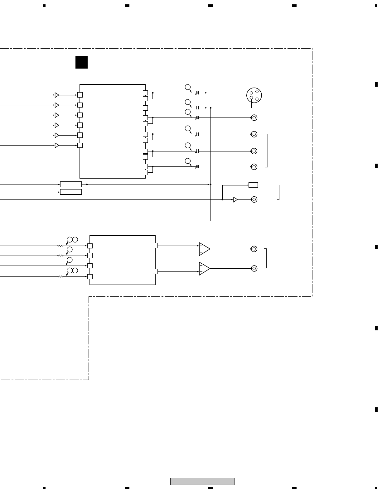
23
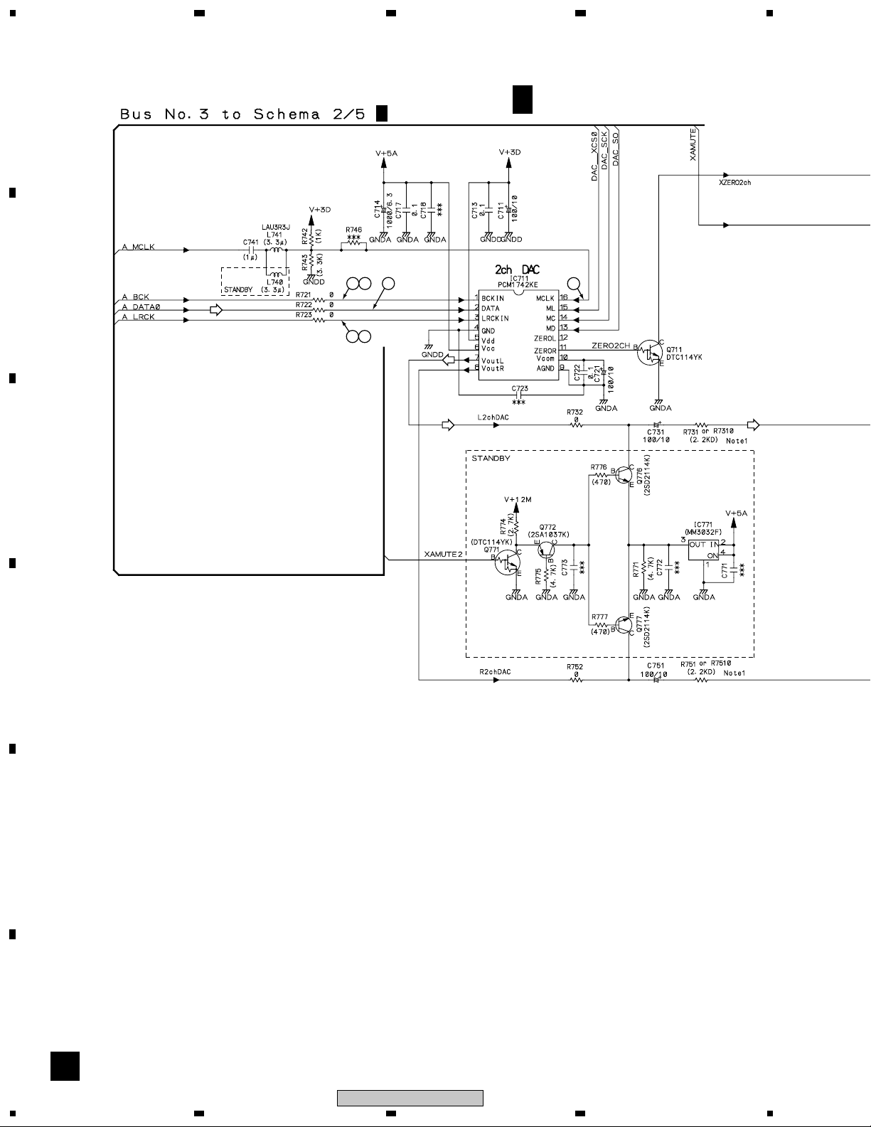
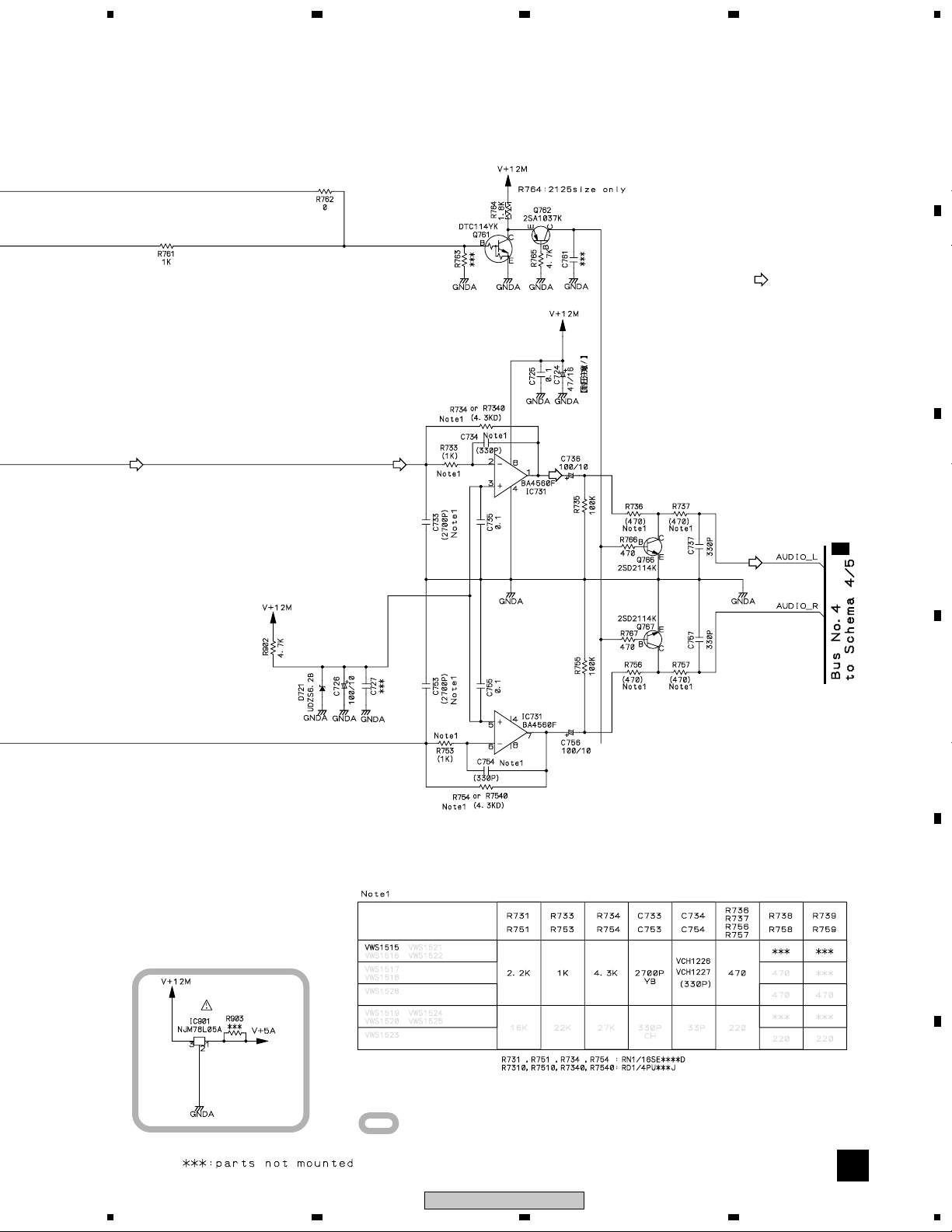
3.5 FJMB ASSY 3/5 [AUDIO BLOCK]
4
A
B
2/5
B
C
4 87
5 6
B 3/5
FJMB ASSY (VWS1515)
3
D
E
F
26
B
3/5
DV-353-K
1234
5
678
A
3– 8: Refer to "3.1.3 WAVEFORMS".
: AUDIO SIGNAL ROUTE
B
4/5
B
C
D
E
: The power supply is shown with the marked box.
3/5
B
DV-353-K
5
6
7
8
27
F
1
23
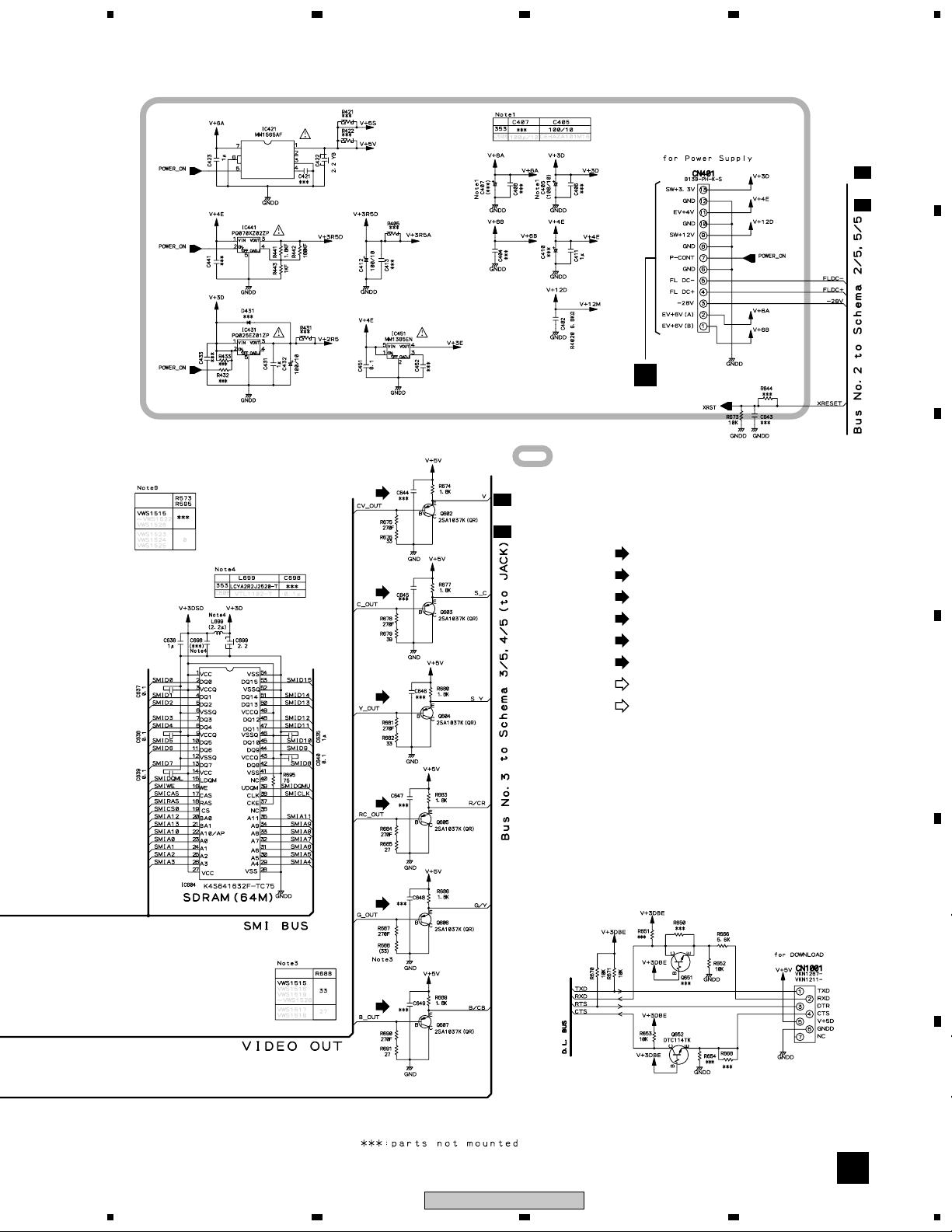
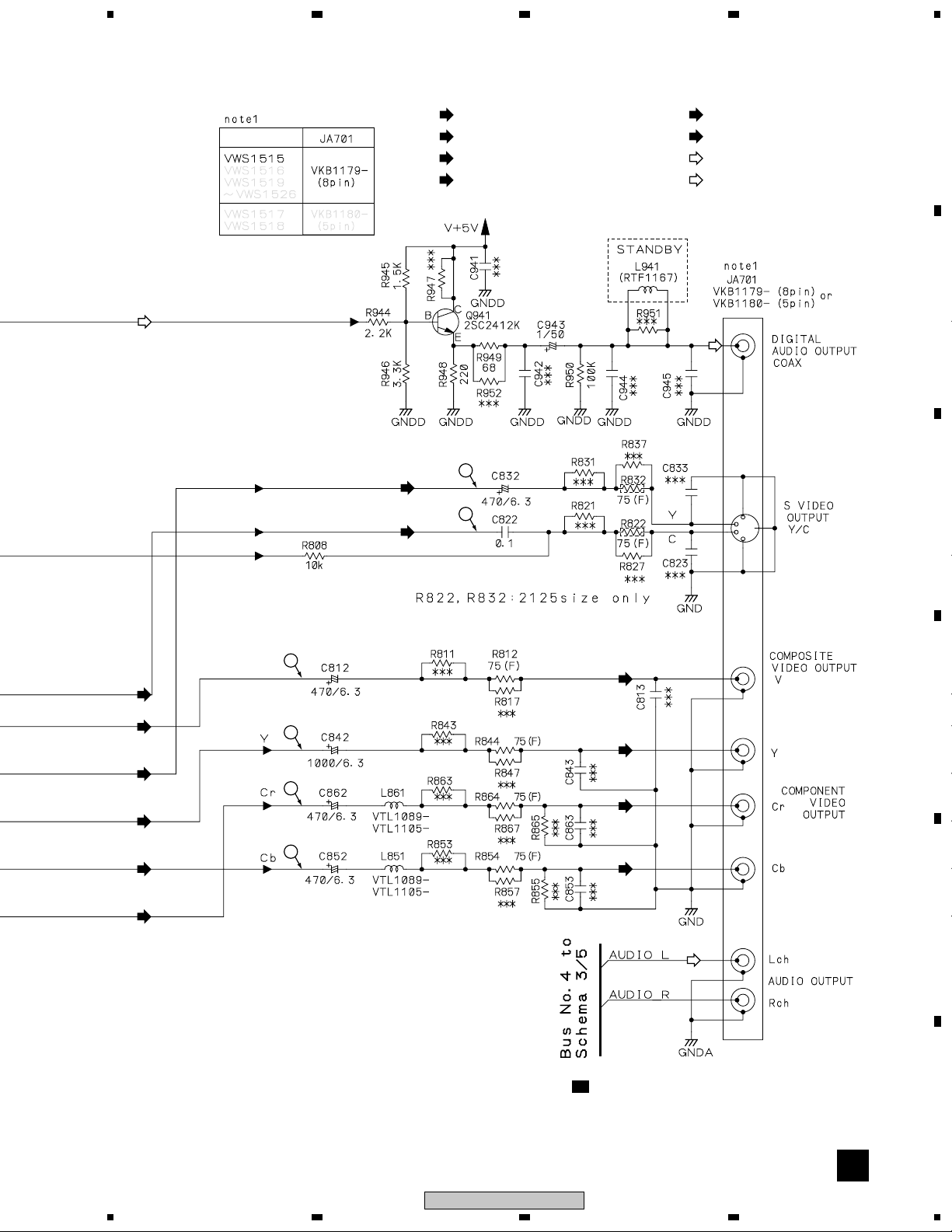
3.6 FJMB ASSY 4/5 [VIDEO BLOCK]
A
4
B 4/5
FJMB ASSY (VWS1515)
(D)
2/5
B
B
C
(D) (D) (D)
(S_C)
D
E
F
(V)
(S_Y)
(G/Y)
(B/Cb)
(R/Cr)
(S_C)
(V)
(S_Y)
(G/Y)
(B/Cb)
(R/Cr)
28
B
4/5
DV-353-K
1234
5
678
(D)
(S_Y)
(S_C)
(V)
: V SIGNAL ROUTE
(S_C)
: S-VIDEO OUT C SIGNAL ROUTE
(S_Y)
: S-VIDEO OUT Y SIGNAL ROUTE
(R/Cr)
: R/Cr SIGNAL ROUTE
13
14
(G/Y)
: G/Y SIGNAL ROUTE
(B/Cb)
: B/Cb SIGNAL ROUTE
: AUDIO SIGNAL ROUTE
(D)
: AUDIO(DIGITAL) SIGNAL ROUTE
(D)
A
B
C
(S_C)
(S_Y)
(G/Y)
(B/Cb)
(R/Cr)
9
(V)
10
12
11
(V)
D
(G/Y)
(R/Cr)
(B/Cb)
E
3/5
B
9– !: Refer to "3.1.3 WAVEFORMS".
4/5
B
DV-353-K
5
6
7
8
29
F
1
23
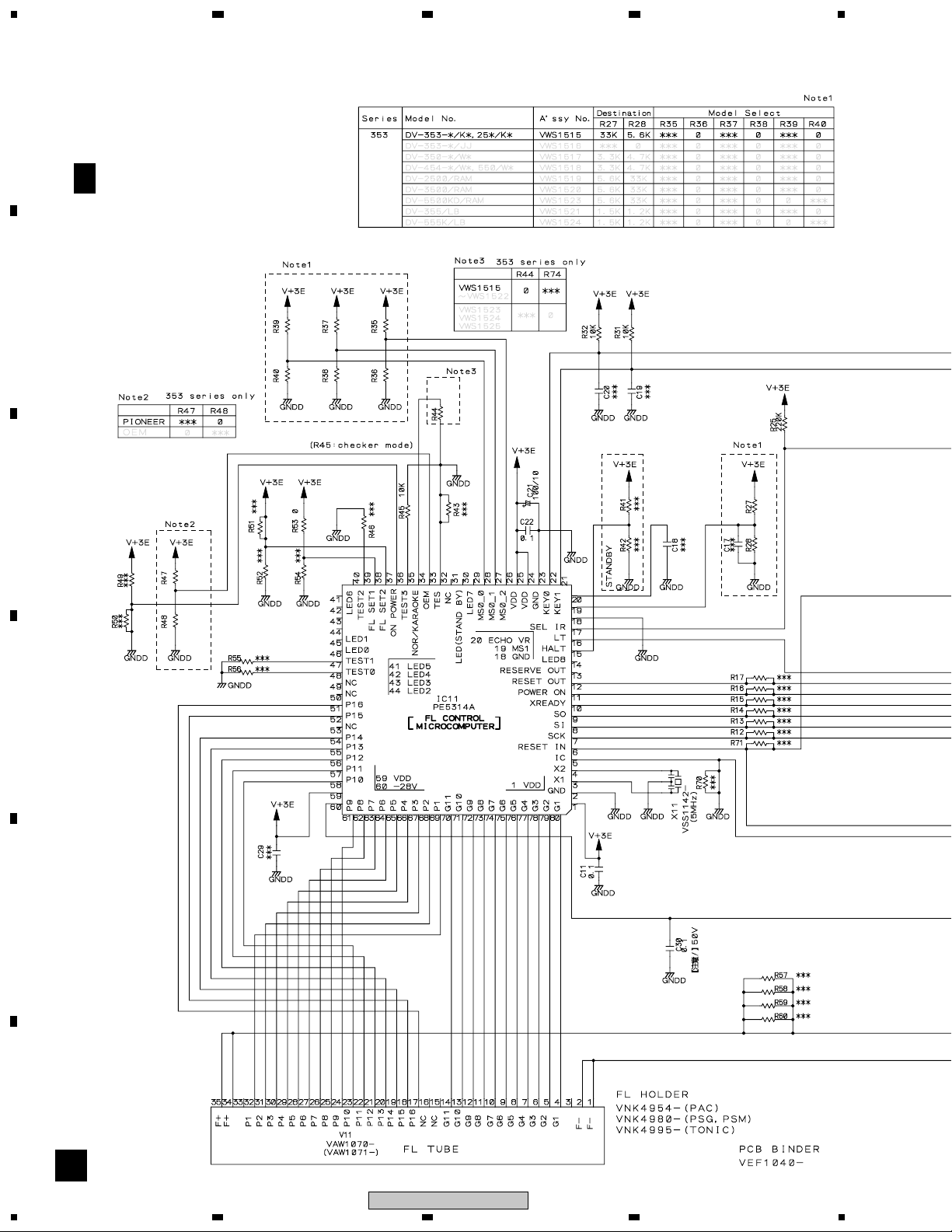
3.7 FJMB ASSY 5/5 [FL CONTROL BLOCK]
A
4
B 5/5
B
C
FJMB ASSY (VWS1515)
D
E
F
30
B
5/5
DV-353-K
1234
 Loading...