

Page 1
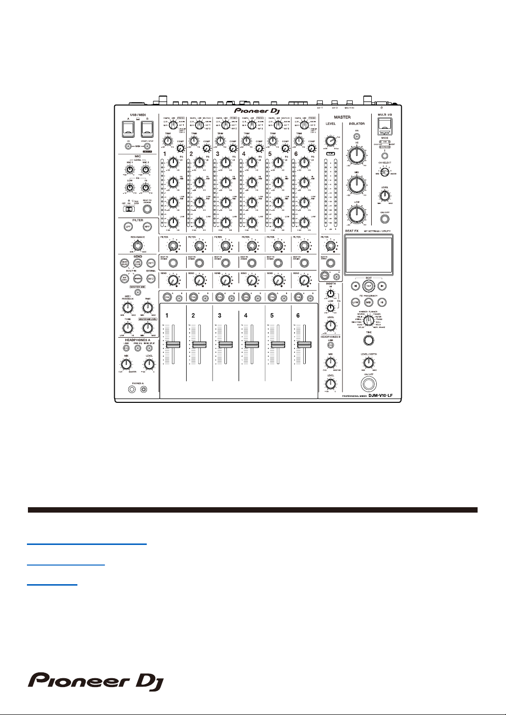
DJ Mixer
DJM-V10-LF
For FAQs and other support information for this product, visit the websites above.
Instruction Manual
pioneerdj.com/support/
rekordbox.com
kuvo.com
Page 2

Contents
Before you start ................................................................................... 5
How to read this manual .........................................................................5
What’s in the box.....................................................................................5
User guides .............................................................................................6
PRO DJ LINK ........................................................................................ 7
Part names ........................................................................................... 8
Top panel ................................................................................................8
Front panel ..............................................................................................9
Rear panel...............................................................................................9
Touch display ........................................................................................12
PC/Mac setup ..................................................................................... 13
Audio driver software ............................................................................13
Installation .............................................................................................14
Setting Utility .........................................................................................15
Connections ....................................................................................... 20
Connecting to the input terminals..........................................................20
Connecting to the output terminals .......................................................21
Connecting to the terminals on the top and front panels.......................22
Connecting external FX units ................................................................23
Audio output ...................................................................................... 25
Channel section/Master section ............................................................26
Outputting sound...................................................................................29
Adjusting the sound...............................................................................30
Setting the fader curves ........................................................................30
Adjusting the left/right sound balance ...................................................31
Master Isolator ................................................................................... 33
Master Isolator section ..........................................................................33
2
Page 3

Adjusting the master sound...................................................................34
Monitoring sound .............................................................................. 35
Headphones A/B sections.....................................................................35
Monitoring with headphones .................................................................37
Booth section ........................................................................................38
Using a booth monitor ...........................................................................38
Microphones ...................................................................................... 39
MIC section ...........................................................................................39
Using a microphone ..............................................................................40
Filter .................................................................................................... 41
Filter section..........................................................................................41
Using the Filter ......................................................................................42
Send .................................................................................................... 43
Send section .........................................................................................43
Routing effect sounds to the channels ..................................................44
Routing effect sounds to the master output ..........................................46
Send types and settings........................................................................48
Multi I/O............................................................................................... 50
Multi I/O section ....................................................................................52
Using Multi I/O.......................................................................................53
Beat FX ............................................................................................... 54
Beat FX section.....................................................................................55
Touch display ........................................................................................56
Using Beat FX .......................................................................................58
Setting the BPM manually.....................................................................59
Beat FX types and settings ...................................................................60
USB/MIDI............................................................................................. 65
USB/MIDI section..................................................................................65
Controlling MIDI software......................................................................66
3
Page 4

Controlling an external MIDI sequencer................................................67
Settings............................................................................................... 68
Utility/My settings screens.....................................................................68
Changing the settings ...........................................................................69
Utility settings ........................................................................................70
My Settings ...........................................................................................73
Saving My Settings to a storage device ................................................77
Loading My Settings saved on a storage device...................................78
Restoring the factory settings................................................................79
Specifications .................................................................................... 80
Block diagram .......................................................................................83
Additional information ...................................................................... 84
Troubleshooting ....................................................................................84
LCD display...........................................................................................87
Trademarks and registered trademarks ................................................88
Software license notice .........................................................................89
Cautions on copyrights..........................................................................90
4
Page 5

Before you start
How to read this manual
• Thank you for choosing this Pioneer DJ product.
Be sure to read this manual, the “Quick Start Guide” and the “Precautions for Use” which
are also included with this product. These documents include important information that
you should understand before using the unit. In particular, be sure to read the IMPORTANT
SAFETY INSTRUCTIONS.
• In this manual the names of buttons, knobs and terminals that appear on the product, and
the names of buttons, menus etc. in the software on your PC/Mac or mobile device, are
indicated within square brackets ([ ]). (e.g. [File], [CUE] button)
• Please note that the software screens and their specifications, as well as the external
appearance and specifications of the hardware, were still under development at the time
this manual was created and may differ from the final specifications.
• Please note that depending on the operating system version, web browser settings, etc.
operation may differ from the ways described in this manual.
• Please note that the language on the screens of the software described in this manual may
differ from the language on your screen.
What’s in the box
• Power cord
• Warranty (for some regions) *
• Quick Start Guide
• Precautions for Use
* Only products in Europe.
Products in North America and Japan include warranty information in the “Precautions for
Use”.
5
Page 6

Before you start
User guides
rekordbox: rekordbox Introduction, Instruction Manual
Refer to the “rekordbox Introduction” to find out how to set up rekordbox, and see the
“Instruction Manual” to find out how to use rekordbox.
Visit the URL below to find these user guides.
rekordbox.com/manual
6
Page 7
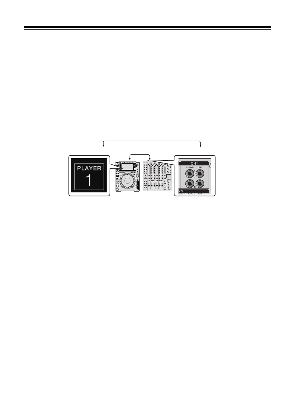
PRO DJ LINK
PLAYER 1 CH 1
Audio cable
You can use PRO DJ LINK functions by connecting the unit via a LAN cable to a PRO DJ
LINK compatible multi player and a PC/Mac running rekordbox.
• You can connect up to 6 multi players and up to 2 computers (PC/Mac) to the unit via a
switching hub (depending on the type of multi player you connect, you may only be able to
use PRO DJ LINK functions on up to 4 players).
• Use a 100BASE-TX compatible switching hub that is supported by multi players. Some
switching hubs may not work properly with selected devices.
• Set the multi player number to the channel number which the audio cable is connected to.
• For details on PRO DJ LINK, see the instruction manuals for the relevant multi players and
rekordbox.
pioneerdj.com/support/
Quantize
When you are playing a track analyzed by rekordbox, the unit adds BEAT FX by automatically
synchronizing it with the beat according to the track’s grid information. This happens even if
you operate the [ON/OFF] button of [BEAT FX] and [X-PAD] roughly.
LINK MONITOR
You can browse and monitor via headphones the sound of tracks in rekordbox on a PC/Mac
or in a multi player while playing a different track (page 35).
• To monitor the sound of rekordbox, click [Preferences] > [Audio] and mark the [Use
“LINK MONITOR” of PIONEER DJ Mixers] check box in rekordbox.
• You can't monitor the sound of tracks in a multi player if the player doesn't support the LINK
MONITOR function.
STATUS INFORMATION
You can check on-air information with multi players.
7
Page 8
Part names
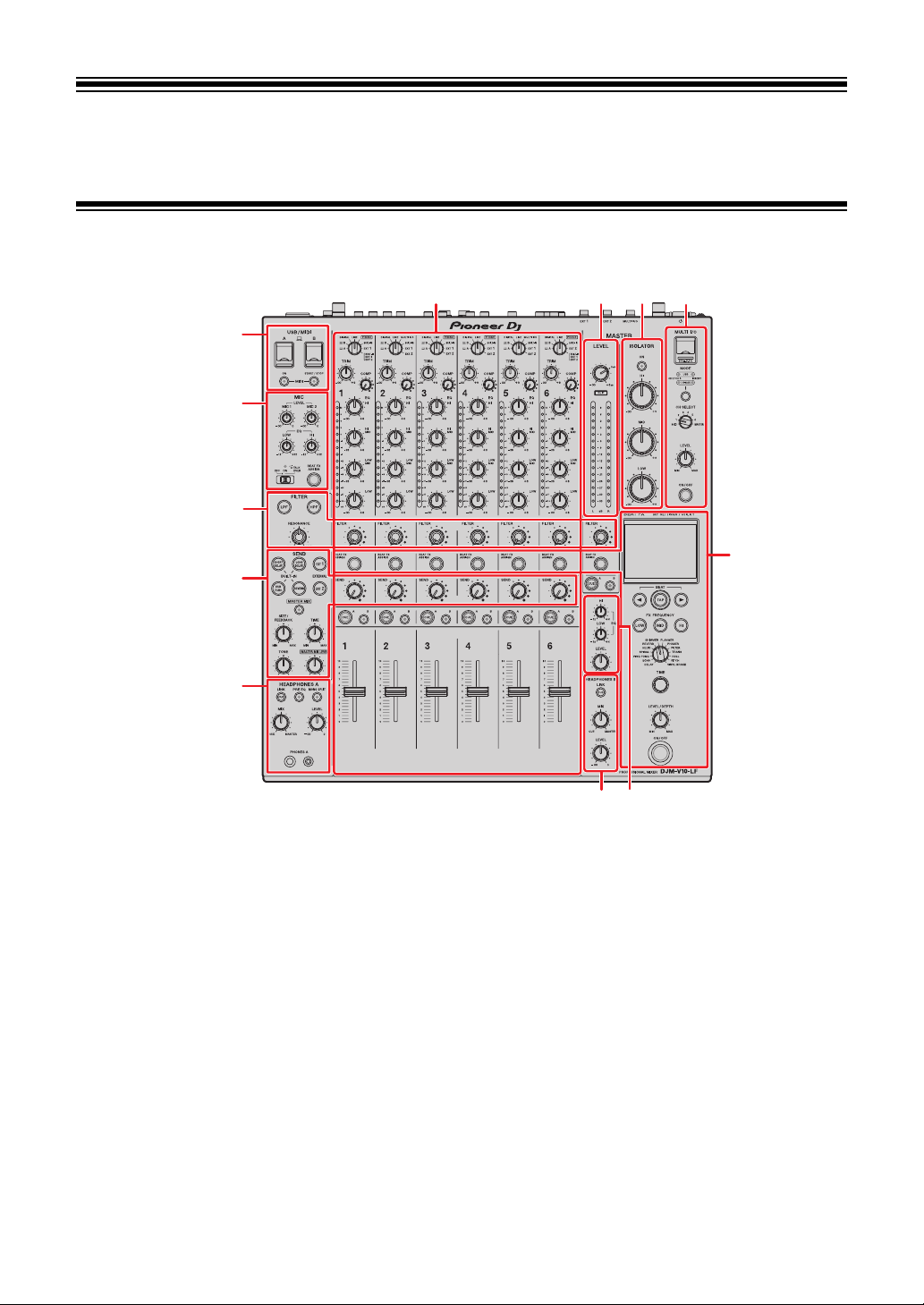
Top panel
6
1
2
3
4
5
8
7
11
5
9
10
1. USB/MIDI section (page 65)
MIC section (page 39)
2.
FILTER section (page 41)
3.
SEND section (page 43)
4.
HEADPHONES (A/B) section (page 35)
5.
6. Channel section (page 26)
7. MASTER section (page 26)
8. MASTER ISOLATOR section (page 33)
MULTI I/O section (page 52)
9.
BEAT FX section (page 55)
10.
BOOTH section (page 38)
11.
8
Page 9
Front panel
1
10
1 2 452 6
7
891112131415
17
3
16
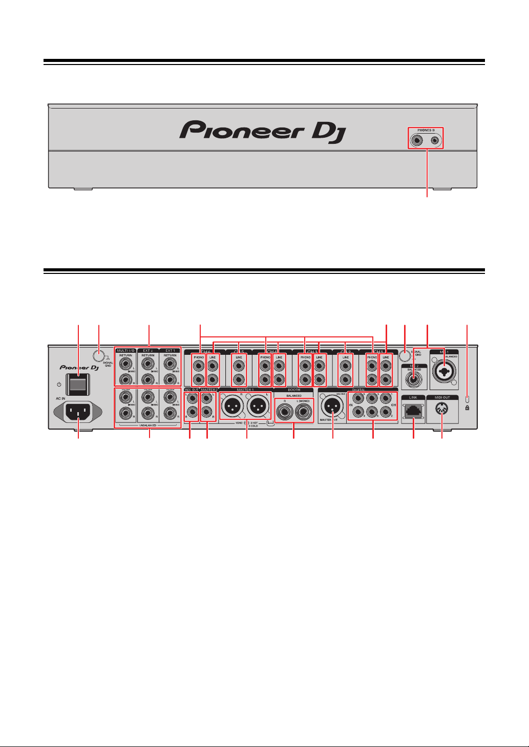
1. PHONES B terminals (pages 22, 35)
Rear panel
Part names
1. button
Turns the unit on and off.
SIGNAL GND terminals (page 20)
2.
Connect a turntable’s ground wire.
Reduces noises that occur when a turntable is connected to the unit.
3. MULTI I/O, EXT2, EXT1 RETURN terminals (1/4”/6.35 mm, TS) (pages 23, 24)
Connect to output terminals on external FX units.
• If you connect equipment to the [L (MONO)] terminal only, the sound input to the [L
PHONO terminals (RCA) (page 20)
4.
Connect phono-level (MM cartridge) output devices.
• Do not input line-level signals to the terminals.
(MONO)] terminal is also input to the [R] channel.
9
Page 10

Part names
• Remove the short-circuit pin plugs from the terminals when connecting devices.
When you are not using the terminals, attach the short-circuit pin plugs to cut out
external noises.
WARNING
Keep the short-circuit pin plugs out of the reach of children and infants. If accidentally
swallowed, contact a doctor immediately.
5.
LINE terminals (RCA) (page 20)
Connect multi players or line-level output devices.
6.
MIC1 terminal (XLR or 1/4”/6.35 mm, TRS), MIC2 terminal (1/4”/6.35 mm, TRS)
(page 20)
7. Kensington security slot
Connect a cable lock.
8. MIDI OUT (5-pin DIN) (pages 21, 67)
LINK terminal (pages 7, 20)
9.
Connect to a LINK terminal on a PC/Mac running rekordbox or a PRO DJ LINK
compatible multi player.
• Use a switching hub (100BASE-TX compatible type) to connect multiple devices.
DIGITAL IN CH terminals (RCA) (page 20)
10.
Connect to a digital coaxial output terminal on a multi player, etc.
• Sound may break when the output signal’s sampling frequency changes.
DIGITAL MASTER OUT terminal (XLR (AES/EBU)) (page 21)
11.
Connect to a digital terminal on a preamplifier, etc.
Outputs the master sound in AES/EBU format.
• Do not connect to an analog input terminal or connect a power cord from another
product to this terminal.
BOOTH terminals (1/4”/6.35 mm, TRS) (page 21)
12.
Connect a booth monitor.
• If you connect equipment to the [L (MONO)] terminal only, mono sound is output.
MASTER1 terminals (balanced XLR) (page 21)
13.
Connect to analog input terminals on a power amplifier, etc.
• Use the terminals for balanced output only.
• Do not connect a power cord from another product to the terminals.
10
Page 11

Part names
14. MASTER2 terminals (RCA) (page 21)
Connect to analog input terminals on a power amplifier, etc.
15. REC OUT terminals (RCA) (page 21)
Connect a device for recording.
MULTI I/O, EXT2, EXT1 SEND terminals (1/4”/6.35 mm, TS) (pages 23, 24)
16.
Connect to input terminals on external FX units.
• If you connect equipment to the [L (MONO)] terminal only, mono sound is output.
AC IN (page 20)
17.
Connect to a power outlet with the supplied power cord.
11
Page 12
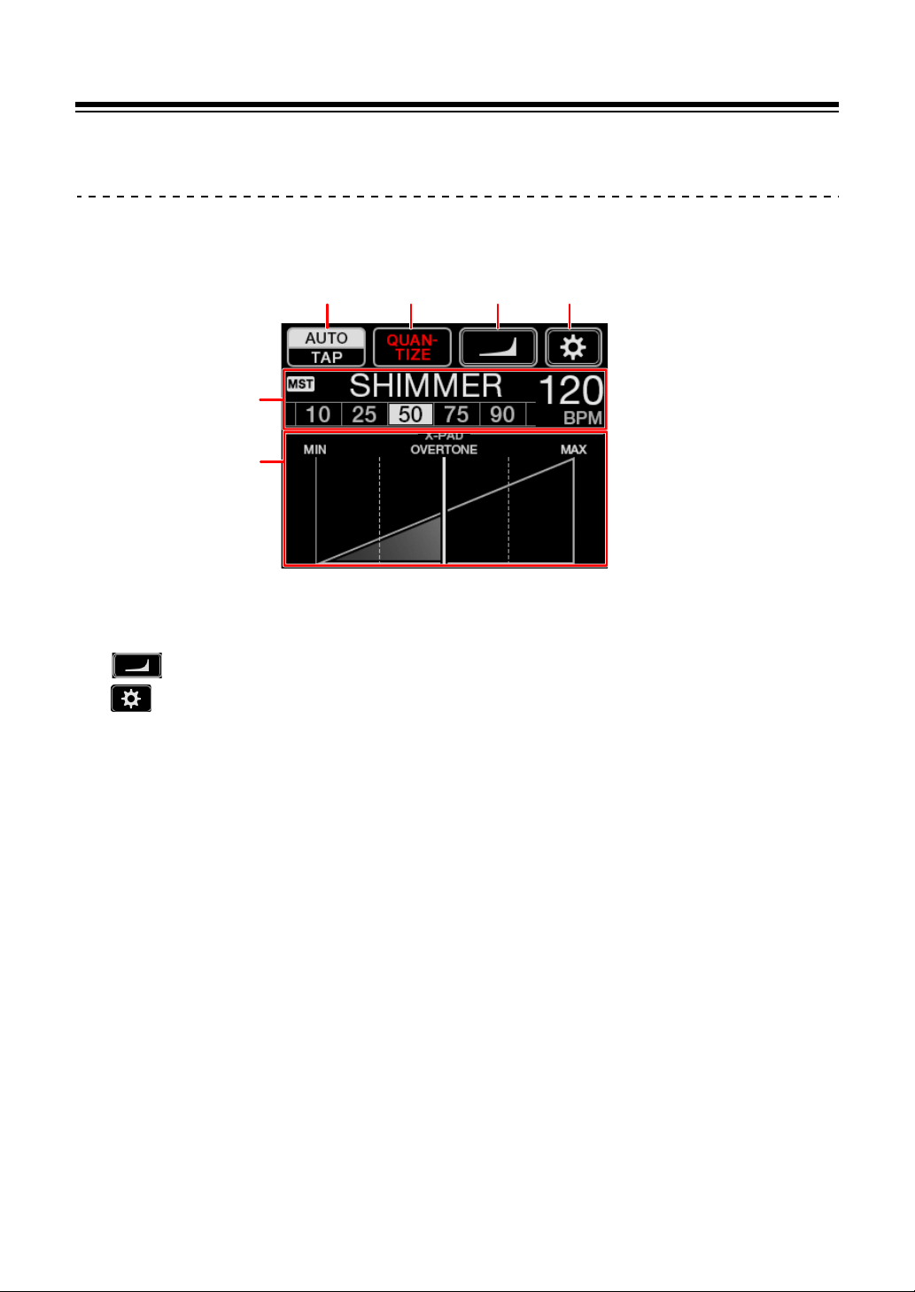
Touch display
5
12 34
6
Main screen (display/touch keys)
Part names
1. AUTO/TAP (page 56)
2. QUANTIZE (page 54)
3.
4.
5. Effect settings display (page 56)
6. X-PAD (page 56)
(fader curve settings) (page 30)
(UTILITY/MY SETTINGS) (page 69)
12
Page 13

PC/Mac setup
Audio driver software
To input or output your PC/Mac’s audio to/from the unit, install the dedicated audio driver
software on your computer.
Setting Utility will also be installed with the audio driver software.
• For the latest system requirements, compatibility, and supported operating systems, visit
the URL below.
pioneerdj.com/support/
• Operation is not guaranteed on all PC/Mac models, even if the system requirements are
met.
• Operation is not guaranteed when multiple units are connected to a PC/Mac.
• If a PC/Mac without the audio driver software installed is connected to the unit, errors may
occur on the PC/Mac.
• Malfunctions may occur due to incompatibility with other software installed on a PC/Mac.
13
Page 14

PC/Mac setup
Installation
Notes on installation
• Turn the unit off and disconnect the USB cable connected to the unit and the PC/Mac
before installation.
• Close all applications running on the PC/Mac before installation.
• You will need admin rights to install the audio driver software to your PC/Mac.
• Read the License Agreement terms carefully before installation.
• If you quit the installation halfway through, perform the installation procedure from the
beginning again.
Downloading the audio driver software
Download the dedicated audio driver software to your PC/Mac from the URL below.
pioneerdj.com/support/
Installing the audio driver software
1 Double-click the downloaded installation file.
2 Read the License Agreement terms carefully.
If you agree to the terms, mark the [Agree] check box and
click [OK].
•
If you do not agree to the License Agreement terms, click [
[
Cancel
] (for Windows®) to cancel the installation.
3 Follow the on-screen instructions to complete the installation.
Disagree
] (for Mac)/
14
Page 15
PC/Mac setup
Setting Utility
You can check and set connections between the unit and a PC/Mac using the Setting Utility
installed on the PC/Mac.
Launching Setting Utility
1 Click [Pioneer] > [DJM-V10 Setting Utility] from the
applications list on a PC/Mac.
Setting Utility launches.
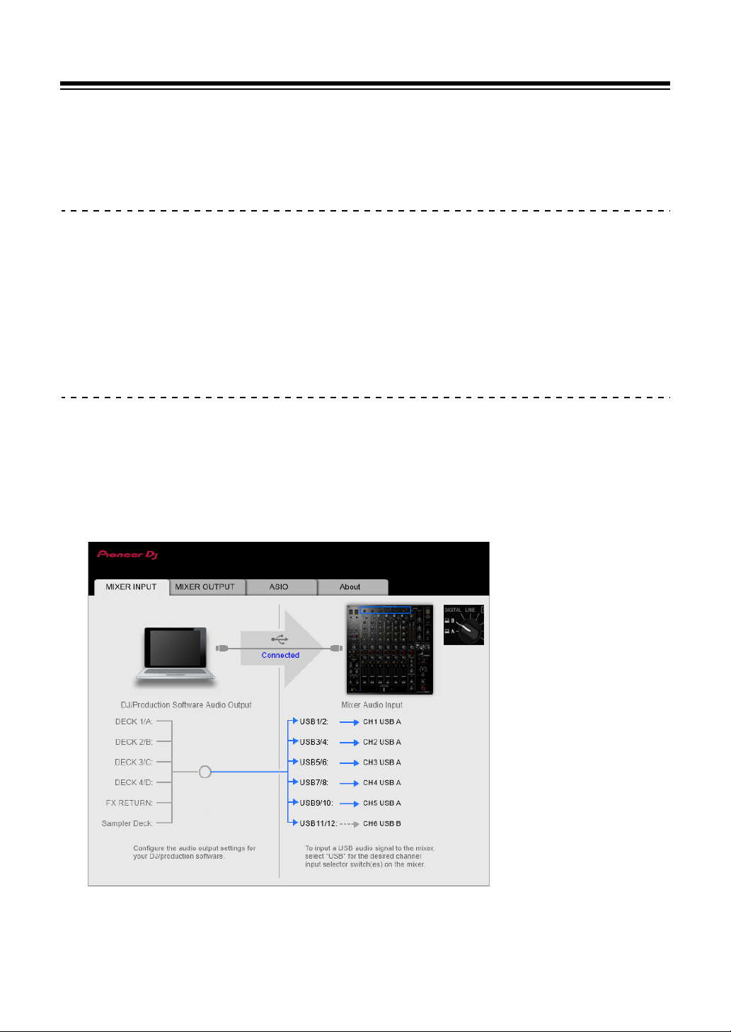
Checking the status of the input selector switches on the
unit
1 Click the [MIXER INPUT] tab.
15
Page 16
PC/Mac setup
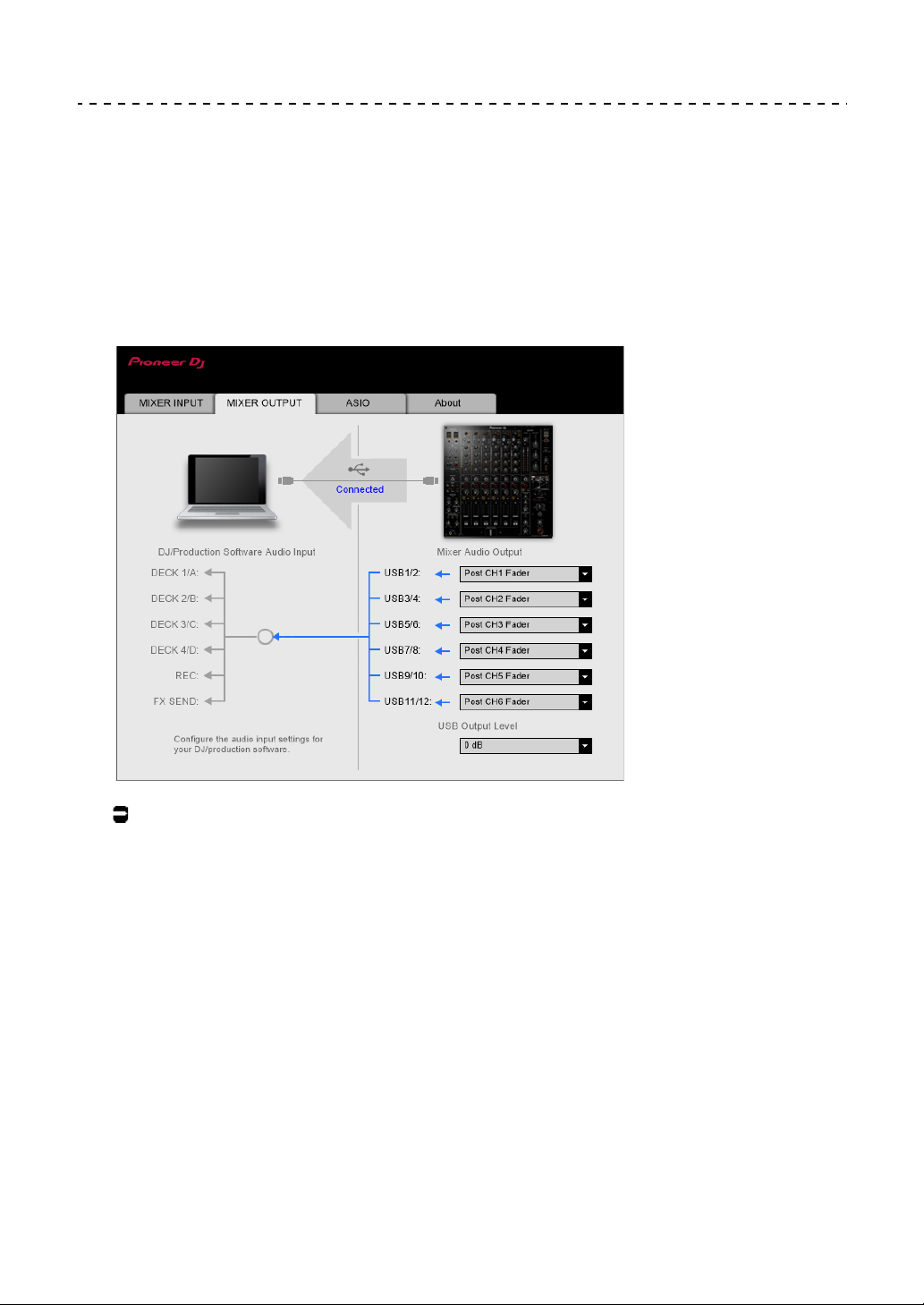
Setting the audio data output from the unit to a PC/Mac
1 Click the [MIXER OUTPUT] tab.
2 Click the pull-down menu under [Mixer Audio Output] and
select the audio data output from the unit to the PC/Mac.
Read more: [Mixer Audio Output] pull-down menu (page 19)
3 Click the pull-down menu under [USB Output Level] and
select a level of volume output from the unit.
•
Set the volume in [
expect using the volume adjustment in your DJ application. Note that the sound may be
distorted if you set the volume too high.
USB Output Level
] when you cannot produce as much volume as you
16
Page 17
PC/Mac setup
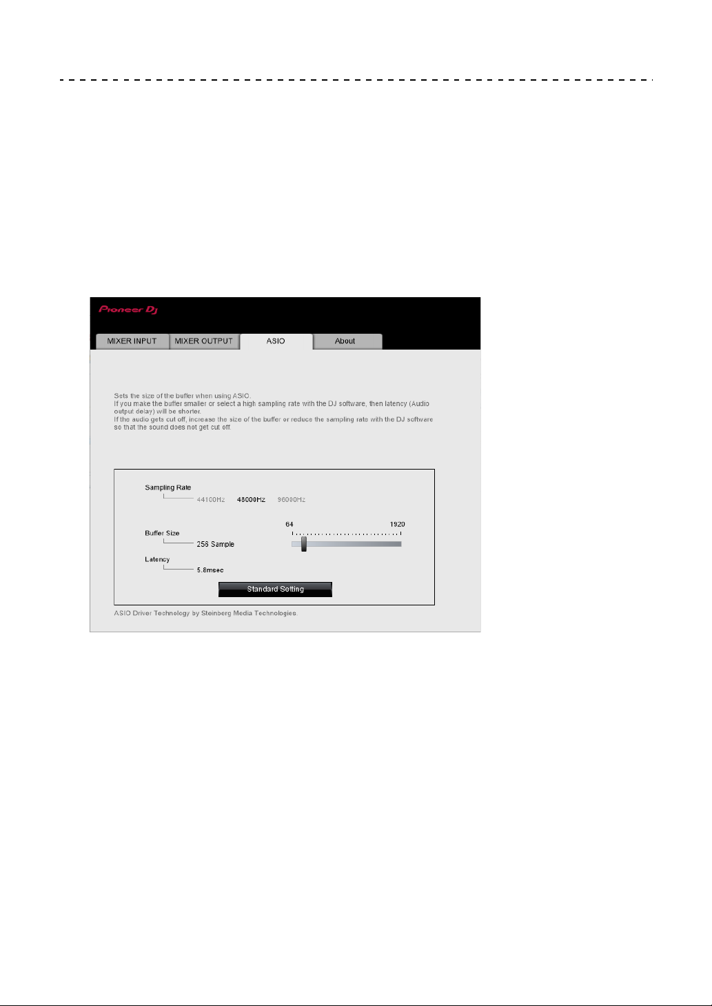
Adjusting the buffer size (for Windows ASIO)
• Close any running applications (DJ applications, etc.) which use the unit as the default
audio device before adjusting the buffer size.
1 Click the [ASIO] tab.
2 Adjust the buffer size with the slider.
• Breaks in sound are less likely to occur if you set a large buffer size, but this
increases time lag due to the latency of audio data transmission.
17
Page 18
PC/Mac setup
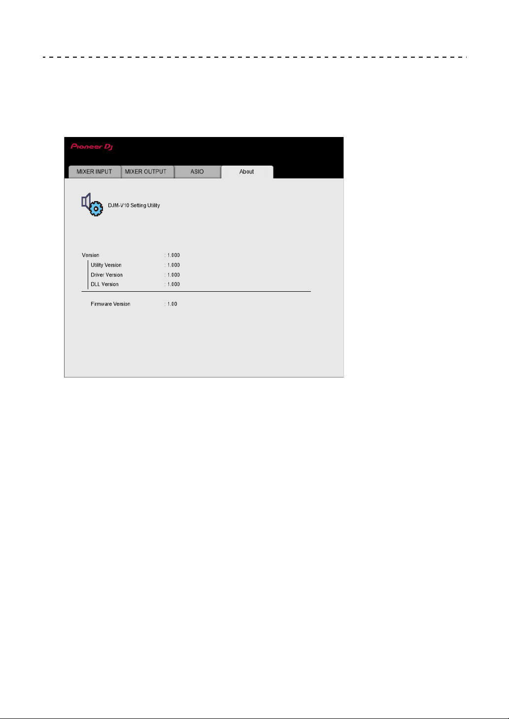
Checking the firmware and software versions
1 Click the [About] tab.
18
Page 19

[Mixer Audio Output] pull-down menu
PC/Mac setup
#: indicates channel number
CH1 (USB1/2), CH3 (USB5/6),
CH4 (USB7/8), CH6 (USB11/12)
CH# Control Tone PHONO
CH# Control Tone LINE
CH# Control Tone DIGITAL
1
1
1
CH2 (USB3/4), CH5 (USB9/10)
CH# Control Tone LINE
CH# Control Tone DIGITAL
Post CH# Fader Post CH# Fader
FX SEND(for rekordbox dj)
CROSSFADER A
CROSSFADER B
3
3
2
FX SEND(for rekordbox dj)
CROSSFADER A
CROSSFADER B
MIC MIC
MIX(REC OUT)
4
MIX(REC OUT)
—
1
1
2
3
3
4
EXT1(SEND EXTERNAL)
EXT2(SEND EXTERNAL)
1
Available for software applications that support the function. Outputs sound at the volume
4
4
EXT1(SEND EXTERNAL)
EXT2(SEND EXTERNAL)
4
4
input to the unit regardless of the [USB Output Level] setting.
2
Available for software applications that support the function.
3
Not available for this unit.
4
For uses other than recording, be sure to set the DJ application so that no sound loop
occurs. Sound may be input or output at an unintended volume level when a sound loop
occurs.
19
Page 20
Connections
L
R
L
R
L
R
L
R
L
R
L
R
L
R
L
R
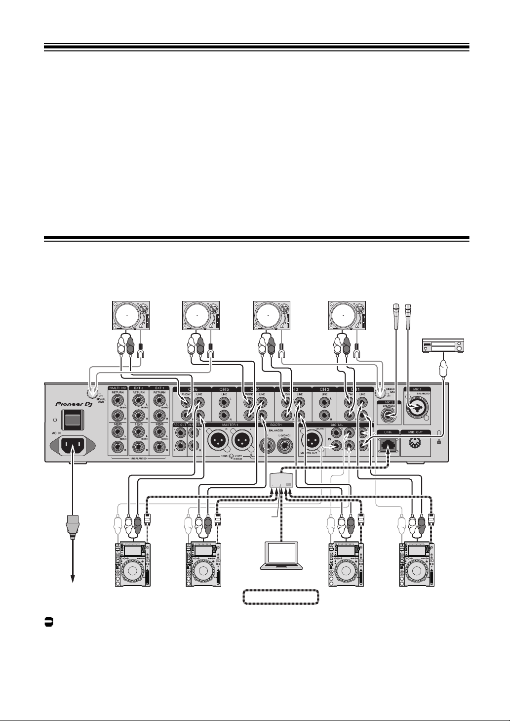
rekordbox
PRO DJ LINK
Turntable
PC/Mac
Multi players
To power outlet
Microphones
Digital audio
output device
Turntable
Turntable
Turntable
Multi players
Switching
hub
Turn the unit off and disconnect the power cord before connecting other units.
Connect the power cord after all the connections are complete.
• Use the supplied power cord.
• Read the instruction manuals for the devices you are going to connect with the unit.
• Use an STP (CAT5e shielded) LAN cable for the LAN connection.
• Do not disconnect a LAN cable when using PRO DJ LINK.
Connecting to the input terminals
Read more: PRO DJ LINK (page 7)
20
Page 21
Connections
L
R
L
R
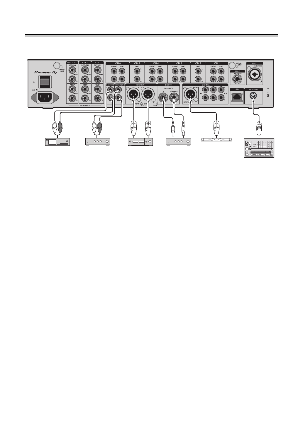
Power amplifierAnalog audio
input device
Power amplifier
Digital audio
input device
MIDI sequencer
Power amplifier
(booth monitor)
Connecting to the output terminals
• Use the [MASTER1] terminals for balanced output. Connecting the terminals to
unbalanced inputs (RCA, etc.) with an XLR-RCA conversion cable (conversion adapter),
etc. results in unwanted noises and/or poor sound quality.
• Use the [MASTER2] terminals for unbalanced input (RCA, etc.).
• Use the [BOOTH] terminals for balanced output. Connecting the terminals to unbalanced
inputs results in unwanted noises and/or poor sound quality.
• Do not connect the power cord from another product to the [MASTER1] or [DIGITAL
MASTER OUT] terminals.
21
Page 22
Connections
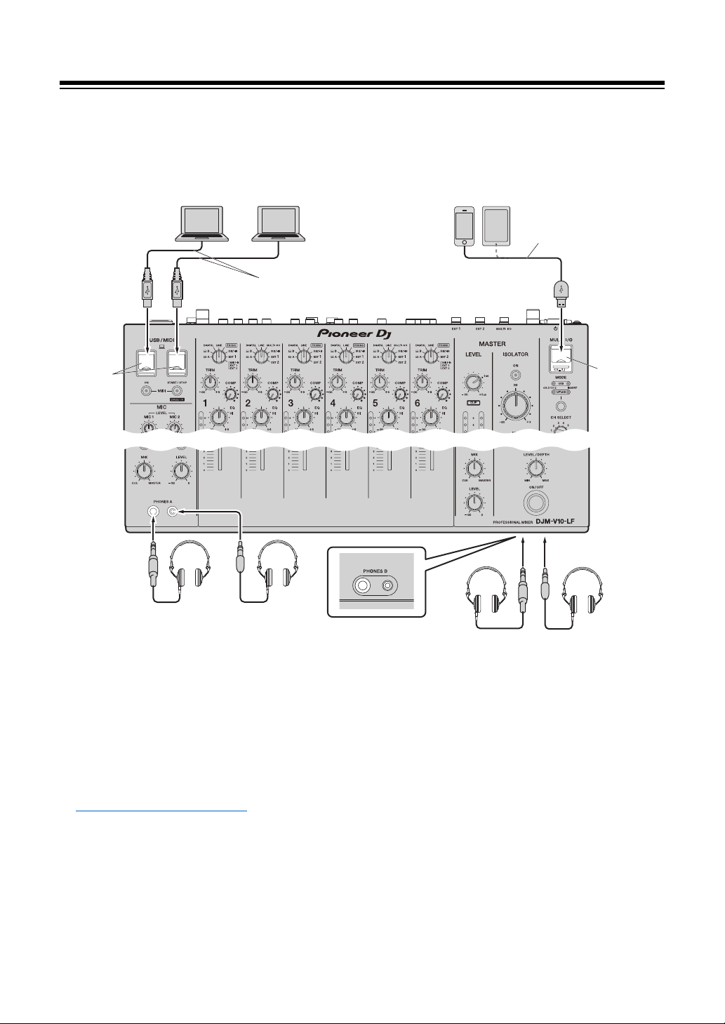
PC/Mac
Mobile devices
Do not use a USB hub.
USB port
cover
USB port
covers
Use a USB cable for the connection.
Do not use a USB hub.
Headphones
Headphones
Connecting to the terminals on the top and front panels
• To input or output your PC/Mac’s audio to/from the unit, install the dedicated audio driver
software on your computer (page 13).
• Do not press or pull the USB port covers with excessive force, or they may be damaged.
• Use a cable supplied with a mobile device for connecting it to the unit.
• For a list of the mobile devices supported by the unit, visit the URL below.
pioneerdj.com/support/
22
Page 23
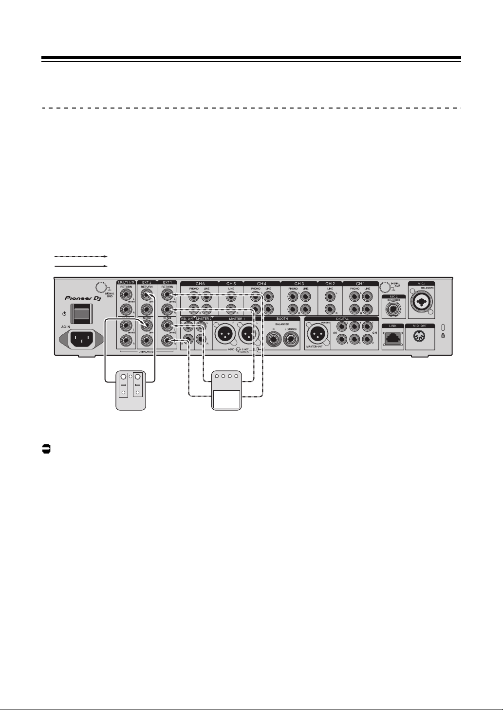
Connections
[EXT1] (SEND/RETURN (1/4" JACK))
[EXT2] (SEND/RETURN (1/4" JACK))
FX unit 1FX unit 2
Connecting external FX units
Connecting to the EXT1/EXT2 terminals
• To use external FX units with SEND, connect as follows.
– [EXT1 SEND] terminals (output) → FX unit 1 → [EXT1 RETURN] terminals (input)
– [EXT2 SEND] terminals (output) → FX unit 2 → [EXT2 RETURN] terminals (input)
• Make sure to connect external FX units to the [EXT1 RETURN] or [EXT2 RETURN]
terminals (input).
• Use devices that can output only effect sounds.
Read more: Send (page 43)
23
Page 24
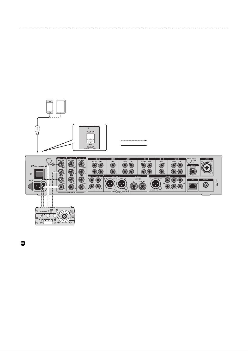
Connections
Mobile devices
MULTI I/O (SEND/RETURN)
USB (Type A) port
FX unit 3
Connecting to the MULTI I/O terminals
• To use external FX units or mobile devices with MULTI I/O, connect as follows.
– [MULTI I/O SEND] terminals (output) → FX unit 3 → [MULTI I/O RETURN] terminals
(input)
– Mobile device connection terminal (USB port) (input/output port) → mobile device
• Make sure to connect external FX units to the [MULTI I/O RETURN] terminals (input).
Read more: Multi I/O (page 50)
24
Page 25

Audio output
Follow the procedures below to output and adjust sound.
– Outputting sound (page 29)
– Adjusting the sound (page 30)
– Setting the fader curves (page 30)
– Adjusting the left/right sound balance (page 31)
To output sound to the [BOOTH] terminals, see Using a booth monitor (page 38).
25
Page 26
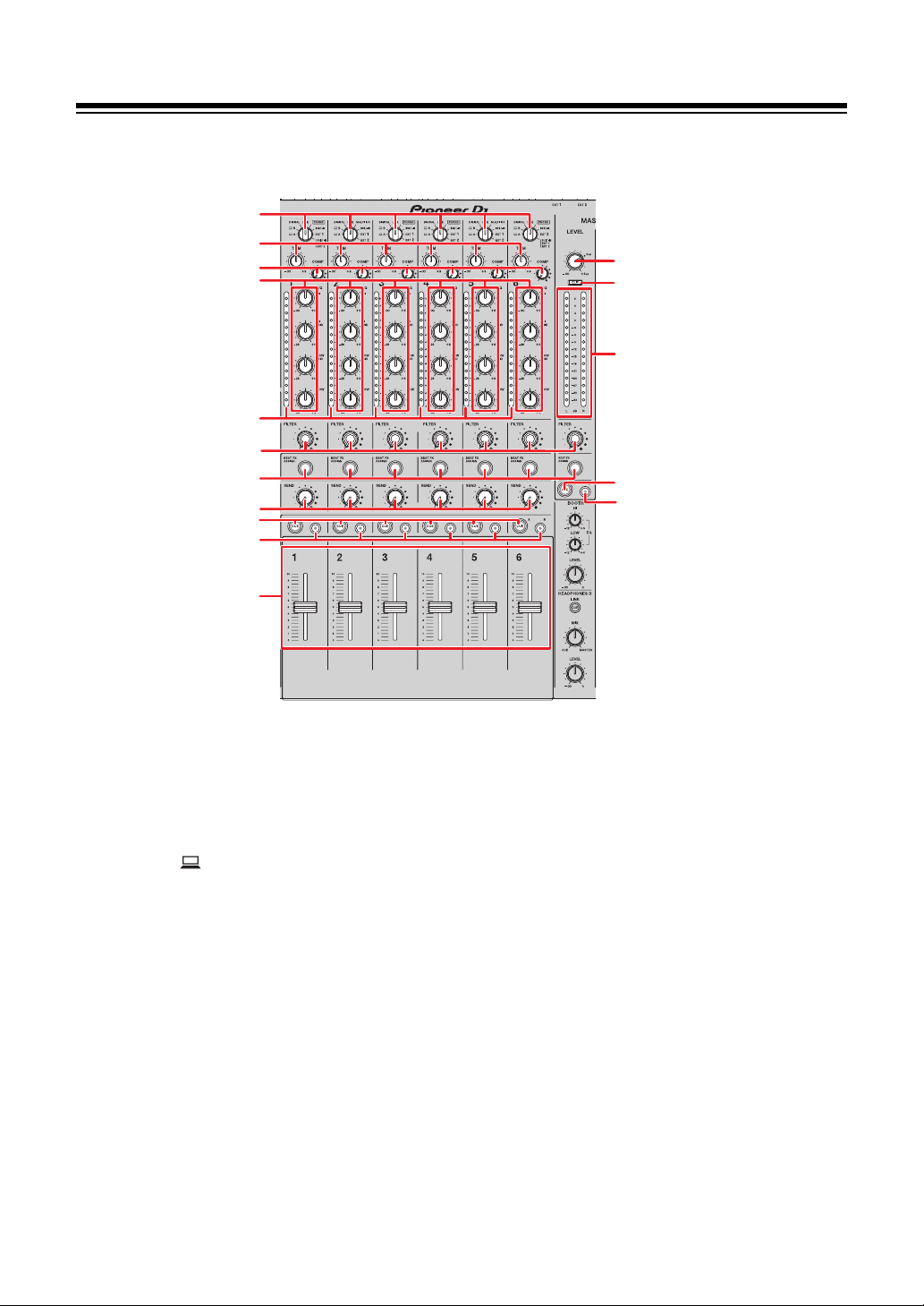
Channel section/Master section
1
2
3
4
5
7
8
6
9
11
12
13
9
14
10
10
Audio output
Channel section
1. Input selector switch (pages 44, 50)
Selects an input sound source.
— [ A,B]: Selects a PC/Mac connected to the [USB] port.
—[DIGITAL]: Selects a multi player connected to the [DIGITAL IN CH] terminal.
—[LINE]: Selects a multi player, etc. connected to the [LINE] terminals.
— [PHONO]: Selects a turntable connected to the [PHONO] terminals.
— [MULTI I/O]: Selects the effect sound input to the [MULTI I/O] terminals (for
selecting [MULTI I/O], set [CH 2/CH 5] with the [MODE] selector button in the
[MULTI
— [BUILT-IN]: Selects the [BUILT-IN] FX of [SEND].
I/O] section).
26
Page 27

Audio output
— [EXT1]: Selects the effect sound of a device connected to the [EXT1 RETURN]
terminals.
— [EXT2]: Selects the effect sound of a device connected to the [EXT2 RETURN]
terminals.
— [BUILT-IN, EXT1, EXT2]
IN
] and [
EXTERNAL
2. TRIM knob
Adjusts the volume for the channel input sound.
3.
COMP knob
Adjusts the compression level.
Turning clockwise increases its effect.
Turning all the way counterclockwise outputs the original sound.
4.
EQ (HI, HI MID, LOW MID, LOW) knobs
Adjusts the volume of each band.
Each knob adjusts in the following range.
: Selects the effect sounds of all [
] buttons).
—[HI]: –∞ dB to +6 dB
— [HI MID]: –26 dB to +6 dB
—[LOW MID]: –26 dB to +6 dB
—[LOW]: –∞ dB to +6 dB
SEND
] buttons ([
BUILT-
Channel level indicator
5.
Displays the volume level before the sound passes through the channel fader.
6. FILTER knob (page 41)
BEAT FX ASSIGN button (page 55)
7.
SEND knob (page 43)
8.
CUE A button (page 35)
9.
CUE B button (page 35)
10.
Channel fader
11.
Adjusts the volume for the channel output sound according to the channel fader curve
specified via [CH FADER CURVE] (page 30). You can control the volume depending on
the scale of the channel fader.
27
Page 28

Audio output
MASTER section
12. LEVEL knob
Adjusts the volume for the master sound.
CLIP indicator
13.
Lights up when excessive volume is output from the [MASTER1] or [MASTER2]
terminals.
14. Master level indicator
Displays the volume level of the master sound output to the [MASTER1], [MASTER2],
and [DIGITAL MASTER OUT] terminals.
28
Page 29

Audio output
Outputting sound
Adjusting the channel input volume
1 Turn the input selector switch to select an input sound
source.
2 Turn the [TRIM] knob to adjust the volume for the input sound.
The channel level indicator lights up when sound is input to the channel.
Adjusting the channel output volume
1 Move the channel fader to adjust the volume for the output
sound.
Adjusting the master sound volume
1 Turn the [LEVEL] knob to adjust the volume for the master
sound.
The master level indicator lights up when the master sound is ouput.
To adjust the master sound, see Master Isolator (page 33).
29
Page 30

Audio output
Adjusting the sound
1 Turn the [EQ (HI, HI MID, LOW MID, LOW)] knobs to adjust the
volume of each band.
2 Turn the [COMP] knob to adjust the compression level.
Setting the fader curves
You can set the channel fader curve.
1 Touch on the main screen.
The [FADER CURVE SETTING] screen appears.
2 Touch a channel fader curve setting in [CH FADER CURVE].
— : Steeply raises the volume when the channel fader is moved close to the top
position.
— : Gradually raises the volume as the channel fader is moved up.
— : Linearly raises the volume as the channel fader is moved up.
3Touch .
The [FADER CURVE SETTING] screen closes.
30
Page 31

Audio output
Adjusting the left/right sound balance
You can adjust the left/right balance for the sounds output from the following terminals.
– [MASTER1]
– [MASTER2]
– [BOOTH]
– [REC OUT]
– [DIGITAL MASTER OUT]
– [USB]
– [PHONES A]
– [PHONES B]
• You can adjust the left/right balance for the sound output from the [USB] port only when
[MIX(REC OUT)] is selected for [Mixer Audio Output] in Setting Utility (page 16).
1 Touch and hold on the main screen.
The [UTILITY] screen appears.
2 Touch [BALANCE].
The [BALANCE] screen appears.
3 Touch / to set a value, or directly touch the position of the
desired value on the slider to adjust the left/right balance.
• Only the left channel sound of stereo audio is output when set to the [L] (leftmost)
position, and only the right channel sound is output when set to the [R] (rightmost)
position.
31
Page 32

4Touch [OK].
• To cancel the setting, touch [CANCEL].
5Touch .
The [UTILITY] screen closes.
Audio output
32
Page 33

Master Isolator
1
2
Adjust the master sound.
Master Isolator section
1. ON button
Turns on and off Master Isolator. The button lights up when it is turned on.
2. HI, MID, LOW knobs
Adjusts the volume of each band.
Each knob adjusts in the following range.
—[HI]: –∞ dB to +9 dB
—[MID]: –∞ dB to +9 dB
—[LOW]: –∞ dB to +9 dB
33
Page 34

Master Isolator
Adjusting the master sound
1 Press the [ON] button to turn on MASTER ISOLATOR.
2 Turn the [HI, MID, LOW] knobs to adjust the volume of each
band.
• Press the [ON] button again to turn off MASTER ISOLATOR.
34
Page 35

Monitoring sound
1
3
4
56
2
1
3
6
7 7 8
8
Headphones A/B sections
1. LINK CUE button
Outputs the LINK MONITOR sound.
PRE EQ button
2.
Sets the sound (pre EQ or post EQ) output to the headphones.
Outputs the pre EQ sound when the button is lit, and the post EQ sound when it is turned
off.
• The post EQ sound is output to [HEADPHONES B].
3. MIX knob
Adjusts the volume balance between the channel with the [CUE] button pressed and the
master sound.
4.
PHONES A terminals
Connect headphones.
• For monitoring sound with [HEADPHONES B], connect headphones to the [PHONES
B] terminals on the front panel (page 22).
35
Page 36

Monitoring sound
5. MONO SPLIT button
Sets the sound output method (MONO SPLIT or stereo) for the headphones.
Outputs the sound of the channel with the [CUE A] button pressed to the left channel of
your headphones, and the [MASTER] sound to the right channel when the button is lit.
Outputs the stereo sound of the channel with the [CUE A] button pressed when the
button is turned off.
• The stereo sound is output to [HEADPHONES B].
6.
LEVEL knob
Adjusts the volume for the headphones monitor sound.
CUE A button
7.
Outputs sound to the [PHONES A] terminals.
CUE B button
8.
Outputs sound to the [PHONES B] terminals.
36
Page 37

Monitoring sound
Monitoring with headphones
1
Connect headphones to the [PHONES A] or [PHONES B]
terminals.
2 Press the [CUE] button ([CUE A], [CUE B] or [LINK CUE]) to
select the sound you want to monitor.
• For monitoring sound via [HEADPHONES B], skip to 5.
3 Press the [PRE EQ] button to set the output sound (pre EQ or
post EQ).
4 Press the [MONO SPLIT] button to set the sound output
(MONO SPLIT or stereo).
5 Turn the [MIX] knob to adjust the volume balance between the
channel with the [CUE] button pressed and the master sound.
6 Turn the [LEVEL] knob to adjust the volume for the channel
with the [CUE] button pressed.
• Press the [CUE] button again to turn off monitoring.
37
Page 38

Booth section
2
1
1. EQ (HI, LOW) knobs
Adjusts the volume of each band.
Each knob adjusts in the following range.
—[HI]: –12 dB to +6 dB
— [LOW]: –12 dB to +6 dB
Monitoring sound
LEVEL knob
2.
Adjusts the volume for the sound output to a booth monitor.
Using a booth monitor
1 Connect a booth monitor to the [BOOTH] terminals.
Read more: Connecting to the output terminals (page 21)
2 Turn the [LEVEL] knob to adjust the volume for the output
sound.
3 Turn the [EQ (HI, LOW)] knobs to adjust the volume of each
band.
38
Page 39

Microphones
1
2
3
5
4
MIC section
1. LEVEL (MIC1, MIC2) knobs
Adjusts the volume for the sound output to the [MIC1] and [MIC2] terminals.
EQ (HI, LOW) knobs
2.
Adjusts the volume output to the [MIC1] and [MIC2] terminals.
Each knob adjusts in the following range.
—[HI]: –12 dB to +12 dB
—[LOW]: –12 dB to +12 dB
MIC indicator
3.
Indicates the setting of the [OFF, ON, TALK OVER] selector switch as follows.
— Off: Set to [OFF].
— Lights up: Set to [ON].
— Blinks: Set to [TALK OV ER ].
OFF, ON, TALK OVER selector switch
4.
Sets the microphone output.
—[OFF]: Turns the microphone off.
—[ON]: Turns the microphone on.
39
Page 40

Microphones
— [TALK OVER]: Sets the microphone to TALK OVER mode. The sound from
channels other than the MIC channels is attenuated when sound over –10 dB is
input to a microphone.
• You can change the TALK OVER mode setting and attenuation level in [TALK OVER]
in [MY SETTINGS] (page 74).
5.
BEAT FX ASSIGN button (page 55)
Using a microphone
1 Connect a microphone to the [MIC1] or [MIC2] terminal.
Read more: Connecting to the input terminals (page 20)
2 Set the [OFF, ON, TALK OVER] selector switch to set the
microphone output.
3 Turn the [LEVEL (MIC1, MIC2)] knob to adjust the microphone
volume.
• Note that turning the knobs too far clockwise outputs the sound at a high volume
level.
4 Turn the [EQ (HI, LOW)] knobs to adjust the volume of each
band.
5 Speak into the microphone.
To add BEAT FX to the microphone sound, see Beat FX section (page 55).
40
Page 41

Filter
1
3
2
You can adjust the cut-off frequency.
The selected filter is applied to all channels, [1] to [6].
Filter section
1. FILTER (LPF, HPF) buttons
Select a filter. The selected button blinks.
— [LPF]: Low Pass Filter
— [HPF]: High Pass Filter
RESONANCE knob
2.
Adjusts the resonance. Turning the knob clockwise increases the resonance.
3. FILTER knob
Adjusts the cut-off frequency.
The setting changes according to the selected [FILTER (LPF, HPF)] button as follows.
— [LPF]: Turning the knob clockwise decreases the cut-off frequency.
— [HPF]: Turning the knob clockwise increases the cut-off frequency.
41
Page 42

Using the Filter
1 Press a [FILTER (LPF, HPF)] button to select a filter.
• If either button is already selected, pressing the other button switches to that filter.
2 Turn the [FILTER] knob to adjust the cut-off frequency.
3 Turn the [RESONANCE] knob to adjust the resonance.
• Press the blinking [FILTER (LPF, HPF)] button to turn the FILTER off.
Filter
42
Page 43

Send
1
7
2
3
4
5
6
Send
You can route the effect sound (reverberation) of one of the built-in FX or an external FX unit
to any channel or the master output.
Send section
1. SEND buttons (page 48)
MASTER MIX button
2.
Turns on and off MASTER MIX. The button lights up when it is turned on, and the effect
sounds of all the [SEND] buttons are routed to the master output.
3. SIZE/FEEDBACK knob (page 48)
TONE knob
4.
Adjusts the filter applied to the [BUILT-IN] effect sound.
5. TIME knob (page 48)
MASTER MIX LEVEL knob
6.
Adjusts the volume for the SEND effect sound that is routed to the master output when
MASTER MIX is turned on.
7. SEND knob
Adjusts the SEND effect level.
For details on the connections, see Connecting to the EXT1/EXT2 terminals (page 23).
43
Page 44

Send
DJM-V10-LF
CH CH6
(RETURN)
TRIM/EQ/FILTER TRIM/EQ/FILTER
BUILT-IN EXT 1 EXT 2
SEND
MASTER ISOLATOR/Master volume
Output
External
FX units
Channel fader
Channel fader
Input
Routing effect sounds to the channels
You can route the effect sound of one of the built-in FX or an external FX unit to any channel.
The selected effect is input to the selected channel.
Read more: Send types and settings (page 48)
1 Turn the input selector switch to select an input sound
source.
For details on the input selector switch, see Channel section/Master section (page 26).
2 Press the [SEND] button to select the effect.
• If you are using an external FX unit, skip to step 6.
3 Turn the [SIZE/FEEDBACK] knob to adjust the quantitative
parameter for the effect.
44
Page 45

Send
4 Turn the [TIME] knob to adjust the time parameter for the
effect.
5 Turn the [TONE] knob to adjust the filter to apply to the effect
sound.
6 Turn the [SEND] knob to adjust the SEND level.
• Press the blinking [SEND] button to turn off SEND.
45
Page 46

Send
DJM-V10-LF
CH
TRIM/EQ/FILTER
BUILT-IN
EXT 1
EXT 2
SEND
Input
MASTER ISOLATOR/Master volume
Output
External
FX units
Channel fader
Routing effect sounds to the master output
You can route the effect sound of one of the built-in FX or an external FX unit to the master
output.
Read more: Send types and settings (page 48)
1 Press the [MASTER MIX] button to turn on MASTER MIX.
2 Press the [SEND] button to select the effect.
• If you are using an external FX unit, skip to step 6.
3 Turn the [SIZE/FEEDBACK] knob to adjust the quantitative
parameter for the effect.
4 Turn the [TIME] knob to adjust the time parameter for the
effect.
46
Page 47

Send
5 Turn the [TONE] knob to adjust the filter to apply to the effect
sound.
6 Turn the [MASTER MIX LEVEL] knob to adjust the effect
sound volume.
7 Turn the [SEND] knob to adjust the SEND level.
• Press the blinking [SEND] button to turn off SEND.
47
Page 48

Send types and settings
You can adjust the following SEND settings with the relevant knobs.
• The selected [SEND] button blinks.
• You can select one of the [BUILT-IN] effect, and [
FX/controls Descriptions
BUILT-IN
SHORT DELAY Adds short delay sounds.
EXT1]/[EXT2] at the same time.
Send
• SIZE/FEEDBACK
•TIME
:
LONG DELAY
• SIZE/FEEDBACK
•TIME
:
DUB ECHO
• SIZE/FEEDBACK
•TIME
:
REVERB
• SIZE/FEEDBACK
:
Turning clockwise increases the feedback.
Turning clockwise increases the delay time.
Adds long delay sounds.
:
Turning clockwise increases the feedback.
Turning clockwise increases the delay time.
Adds reverberating echo by outputting the sounds slightly
delayed from the original sound several times and
attenuating them.
:
Turning clockwise increases the feedback.
Turning clockwise increases the delay time.
Adds reverberation.
:
Turning clockwise increases the room size.
•TIME
EXTERNAL
EXT1
EXT2
:
1
1
Turning clockwise increases reverberation time.
Adds the effect sound of an external FX unit connected to the
[EXT1 SEND] and [EXT1 RETURN] terminals.
Adds the effect sound of an external FX unit connected to the
[
EXT2 SEND
] and [
EXT2 RETURN] terminals.
48
Page 49

1
The [SIZE/FEEDBACK], [TIME], and [TONE] knobs are not available for this setting.
Send
49
Page 50

Multi I/O
DJM-V10-LF
CH MULTI I/O
TRIM/EQ/FILTER
External FX unit/
mobile device
Input
Output
Channel fader
MASTER ISOLATOR/Master volume
Multi I/O
You can route the effect sound of an external FX unit or a mobile device (running an FX
application) to the channels or the master output.
You can route effects in the following ways.
–
INSERT: Replaces the original sound with the effect sound from an external device.
50
Page 51

Multi I/O
DJM-V10-LF
CH3
MULTI I/O
TRIM/EQ/FILTER
CH2
(RETURN
MULTI I/O)
TRIM/EQ/FILTER
External FX unit/
mobile device
Input
Output
Channel fader
MASTER ISOLATOR/Master volume
Channel fader
– CH 2/CH 5: Routes the effect sound from an external device to a channel separate from
the one with the original sound. You can then mix the original sound and the effect sound
using the two channels.
For details on connections, see Connecting to the MULTI I/O terminals (page 24).
51
Page 52

Multi I/O section
1
2
4
5
6
7
3
1. Mobile device connection terminal (USB port)
Connect a mobile device.
USB connection indicator
2.
Multi I/O
Lights up when a compatible mobile device is connected, and blinks when an
incompatible mobile device is connected.
3. MODE selector indicator
Indicates an external FX unit and effect input method selected with the [MODE] selector
button.
4. MODE selector button
Selects an external FX unit and effect input method.
—[USB]: Selects a mobile device connected to the mobile device connection
terminal.
— [1/4"JACK]: Selects an external FX unit connected to the [MULTI I/O RETURN]
terminals.
— [CH 2/CH 5]: Outputs the sound of a channel selected with the [CH SELECT]
switch to an external FX unit or a mobile device, and routes the effected sound to
a channel for which [MULTI I/O] is selected with the input selector switch.
— [INSERT]: Outputs the sound of a channel selected with the [CH SELECT]
CH SELECT switch
5.
Selects a channel to add the MULTI I/O effect to.
switch to an external FX unit or a mobile device, and routes the effected sound to
the channel selected with the [CH SELECT] switch.
52
Page 53

Multi I/O
6. LEVEL knob
Adjusts the volume for the MULTI I/O effect sound.
7.
ON/OFF button
Turns on and off MULTI I/O. The button blinks when it is turned on.
Using Multi I/O
1 Press the [MODE] selector button to select an external FX unit
and effect input method.
2 Turn the [CH SELECT] switch to select a channel to add the
MULTI I/O effect to.
3 Press the [ON/OFF] button to turn on MULTI I/O.
4 Turn the [LEVEL] knob to adjust the volume for the MULTI I/O
effect sound.
• Press the [ON/OFF] button again to turn off MULTI I/O.
• MULTI I/O turns off automatically in the following situations.
– The unit is not connected with an external FX unit.
– [CH 2/CH 5] is selected with the [MODE] selector button, a channel from [1] to [6] is
selected with the [CH SELECT] switch, and [MULTI I/O] is selected with the input
selector switch for the selected channel.
– [CH 2/CH 5] is selected with the [MODE] selector button, and [MASTER] is selected
with the [CH SELECT] switch.
53
Page 54

Beat FX
Beat FX
You can add various effects according to the tempo (BPM = Beats Per Minute) of the track
being played.
If you use the Quantize function in PRO DJ LINK, the unit adds effects by automatically
synchronizing it with the beat according to the track’s grid information analyzed by rekordbox.
This happens even if you operate the [ON/OFF] button of [BEAT FX] and [X-PAD] roughly.
• To use the Quantize function in PRO DJ LINK, connect a PRO DJ LINK compatible multi
player to the unit.
Analyze the tracks in rekordbox beforehand. For details on track analysis, see the
rekordbox Instruction Manual.
Read more: PRO DJ LINK (page 7)
54
Page 55

Beat FX section
2
5
3
4
6
7
8
9
1
Beat FX
1. BEAT FX ASSIGN button
Adds BEAT FX to the channel. The selected button lights up, and blinks when BEAT FX
is on.
• Press the [BEAT FX ASSIGN] button in the [MIC] section to add BEAT FX to the
microphone sound.
2. Touch display (page 56)
BEAT / buttons
3.
Set a beat fraction to synchronize BEAT FX with.
TAP button
4.
Tap the button to manually set a BPM.
Press and hold to turn on the [AUTO] mode.
5.
FX FREQUENCY (LOW, MID, HI) buttons
Select the band ([LOW], [MID], [HI]) to add BEAT FX to. The selected button lights up.
6.
BEAT FX selector switch (page 60)
TIME knob (page 60)
7.
8. LEVEL/DEPTH knob (page 60)
• Turning all the way counterclockwise outputs the original sound.
55
Page 56

9. ON/OFF button
4
12
5
3
6
Turns on and off BEAT FX. The button blinks when it is turned on.
Touch display
Beat FX
1. AUTO/TAP
Selects a BPM measuring mode.
Changes the highlighted (selected) item with each touch.
—[AUTO]: Automatically measures the BPM of the input sound (measuring range:
70 to 180).
—[TAP]: Manually sets a BPM (page 59).
• [AUTO] is automatically set when you turn the unit on.
• Touch and hold [AUTO/TAP] when [TAP] is selected to display the [BPM SETTING]
screen and set a BPM in increments of 0.1.
• The BPM value blinks when it cannot be measured correctly in the [AUTO] setting.
Use the [TAP] mode if this happens.
QUANTIZE
2.
Indicates the status of the Quantize function as follows.
— Lights up in red: The function is turned on.
— Displays [QUANTIZE] and [NO GRID] alternately: Quantize is turned on, but the
unit is not receiving the grid information.
— Lights up in gray: Quantize is turned off.
• The unit may not receive the grid information depending on the playback status of a
connected multi player (e.g. if it is off air, scratching, playing in reverse, etc.).
56
Page 57

Beat FX
3. Selected effect
Displays the name of the selected effect.
4.
Beat/parameter
Highlights the selected beat.
• Parameter is displayed for some effects when you press the [BEAT /] buttons.
The display blinks if you choose a value out of the parameter’s range.
X-PAD
5.
Turns an effect on and off with a touch of [X-PAD].
Adjusts the time and quantitative parameters when you touch or slide your finger on the
the [X-PAD].
• Release the [X-PAD] to turn the effect off.
6. BPM value
Displays the BPM value.
57
Page 58

Beat FX
Using Beat FX
Read more: Beat FX types and settings (page 60)
1 Touch [AUTO/TAP] or [QUANTIZE] to select a BPM measuring
mode.
2 Turn the BEAT FX selector switch to select an effect.
The selected BEAT FX screen appears.
3 Press the [BEAT FX ASSIGN] button to select a channel to add
the effect to.
4 Press the [BEAT /] buttons to set a beat fraction to
synchronize the effect sound with.
5 Press the [FX FREQUENCY (LOW, MID, HI)] buttons to select
the band to add the effect to.
6 Turn the [TIME] and [LEVEL/DEPTH] knobs to adjust the effect
settings.
7 Press the [ON/OFF] button (or touch the [X-PAD]) to turn on
BEAT FX.
The effect is added to the selected channel.
• Press the [ON/OFF] button again to turn off BEAT FX.
58
Page 59

Beat FX
Setting the BPM manually
1 Tap the [TAP] button more than twice in time with the beat of
the track.
The BPM is set according to the average time between taps.
• The beat fraction is set to [1/1] when you set the BPM with the [TAP ] button, and the
length of one beat is set as the effect time.
• You can also set the BPM manually by turning the [TIME] knob while pressing the [TA P ]
button.
• Touch and hold [AUTO/TAP] when [TAP ] is selected to display the [BPM SETTING] screen
and set the BPM in increments of 0.1.
59
Page 60

Beat FX
Beat FX types and settings
You can adjust the following BEAT FX settings with the relevant buttons and knobs, etc.
BEAT FX/controls Descriptions
DELAY
ECHO
1 2
•BEAT /:
•TIME:
• LEVEL/DEPTH:
• X-PAD:
1 2
•BEAT /:
•TIME:
• LEVEL/DEPTH:
Outputs a delay sound once according to the beat.
Delay time with respect to 1 beat of the BPM (beat fraction): 1/16
to 16 beats
Delay time: 1 to 4000 (ms)
Balance between the original sound and the effect sound
Delay time
Outputs a delay sound several times while attenuating it
according to the beat.
Delay time with respect to 1 beat of the BPM (beat fraction): 1/16
to 16 beats
Delay time: 1 to 4000 (ms)
Balance between the original sound and the effect sound
• X-PAD:
PING PONG
•BEAT /:
•TIME:
• LEVEL/DEPTH:
• X-PAD:
1 2
Delay time
Outputs a delay sound with different delay times for the left
and right several times while attenuating it
beat, producing a stereo-like effect.
Delay time with respect to 1 beat of the BPM (beat fraction): 1/16
to 16 beats
Delay time: 10 to 4000 (ms)
Balance between the original sound and the effect sound
Delay time
according to the
60
Page 61

BEAT FX/controls Descriptions
Beat FX
SPIRAL
HELIX
1 2
•BEAT /:
•TIME:
• LEVEL/DEPTH: Balance between the original sound and the effect sound,
• X-PAD:
•BEAT /: Effect time with respect to 1 beat of the BPM (beat fraction):
•TIME:
• LEVEL/DEPTH: Ratio of sound overlay
Adds reverberation to the input sound.
Delay time with respect to 1 beat of the BPM (beat fraction): 1/16
to 16 beats
Delay time: 10 to 4000 (ms)
and feedback
Delay time
Records the input sound, and outputs the recorded sound
repeatedly
1/16 to 16 beats
Effect time: 10 to 4000 (ms)
according to the specified beat fraction.
• X-PAD:
REVERB
1 2
•BEAT /:
•TIME:
• LEVEL/DEPTH:
• X-PAD:
• You can change the attenuation rate by turning the
[LEVEL/DEPTH] knob all the way counterclockwise and
then clockwise. Turn the knob all the way clockwise to fix
the output sound.
Effect time
Adds reverberation to the input sound.
Reverberation level: 1 to 100%
Reverberation level: 1 to 100%
Balance between the original sound and the effect sound
Cut-off frequency for the filter
61
Page 62

BEAT FX/controls Descriptions
Beat FX
SHIMMER
FLANGER
1 2
•BEAT /:
•TIME:
• LEVEL/DEPTH:
• X-PAD:
•BEAT /:
•TIME:
• LEVEL/DEPTH:
• X-PAD:
Adds a sparkling reverberation to the input sound.
Reverberation level: 1 to 100%
Reverberation level: 1 to 100%
Balance between the original sound and the effect sound
Rate of the sparkling effect
Adds a cyclic flanger effect
Moving cycle of the effect with respect to 1 beat of the BPM
(beat fraction)
Moving cycle of the effect
Effect level
Cycle to finely fluctuate the effect
: 1/16 to 64 beats
according to the beat.
: 10 to 32000 (ms)
PHASER Adds
•BEAT /:
•TIME:
• LEVEL/DEPTH:
• X-PAD:
FILTER
•BEAT /:
•TIME:
• LEVEL/DEPTH:
Moving cycle of the effect with respect to 1 beat of the BPM
(beat fraction)
Moving cycle of the effect
Effect level
Cycle to finely fluctuate the effect
Changes the cut-off frequency cyclically for the filter
to the beat.
Moving cycle of the effect with respect to 1 beat of the BPM
(beat fraction)
Moving cycle of the effect
Effect level
a cyclic phaser effect
: 1/16 to 64 beats
: 10 to 32000 (ms)
: 1/16 to 64 beats
: 10 to 32000 (ms)
according to the beat.
according
62
Page 63

BEAT FX/controls Descriptions
Beat FX
• X-PAD:
TRANS Cuts the sound
•BEAT /:
•TIME:
• LEVEL/DEPTH: Balance between the original sound and the effect sound,
• X-PAD:
ROLL
•BEAT /:
Cycle to finely fluctuate the effect
cyclically
Cycle of the cut with respect to 1 beat of the BPM
1/16 to 16 beats
Effect time: 10 to 16000 (ms)
and duty
Cut cycle
Records the input sound when the [ON/OFF] button is
pressed, and outputs the recorded sound repeatedly
according to the specified beat fraction.
Effect time with respect to 1 beat of the BPM (beat fraction): 1/16
to 16 beats
according to the beat.
(beat fraction)
:
•TIME:
• LEVEL/DEPTH:
• X-PAD:
PITCH Adjusts the pitch of the original sound.
•BEAT /:
•TIME:
• LEVEL/DEPTH:
• X-PAD:
Effect time: 10 to 4000 (ms)
Balance between the original sound and the effect sound
Effect time
Pitch of the effect sound: –50 to 100%
Pitch of the effect sound: –50 to 100%
Pitch of the effect sound
Pitch of the effect sound
63
Page 64

BEAT FX/controls Descriptions
Beat FX
VINYL BRAKE
•BEAT /:
•TIME:
• LEVEL/DEPTH:
• X-PAD:
1
If the [BEAT FX ASSIGN] button is pressed on any of the channels, [1] to [6], you cannot
monitor the effect sound, even if you press the [CUE A] or [CUE B] button for the relevant
channel.
2
Only the effect sound remains if you set the channel fader to the [0] position to cut the
input sound.
Slows down the playback speed of the input sound gradually
according to the beat and then stops the playback.
Effect time with respect to 1 beat of the BPM (beat fraction): 1/16
to 16 beats
Effect time: 10 to 4000 (ms)
Playback speed
Effect time
64
Page 65

USB/MIDI
1
2
3
4
If you connect a PC/Mac or mobile device with MIDI software installed, to the unit via a USB
cable, you can control the MIDI software via the unit (page 66).
You can also synchronize an external MIDI sequencer with the tempo (BPM) of the track on
the channel that is selected for adding BEAT FX with the [AUTO] or [QUANTIZE] setting
(page 67).
• For details on the unit’s MIDI messages, visit the URL below.
pioneerdj.com/support/
• Set the MIDI channel for outputting MIDI in [MIDI] in [MY SETTINGS] (page 74). You do not
need to make the setting to output via HID.
USB/MIDI section
1. A, B (USB) ports (page 22)
USB connection indicator
2.
Lights up when a PC/Mac is connected, and blinks when a PC/Mac is connected without
the dedicated audio driver software installed.
• To input or output your PC/Mac’s audio to/from the unit, install the dedicated audio
driver software on your computer (page 13).
3. MIDI ON button
Turns on and off MIDI. The button lights up when it is turned on.
MIDI START/STOP (WAKE UP) button
4.
Sends the MIDI start/stop messages. The button lights up after the start message is sent,
and turns off after the stop message is sent.
Exits standby mode if you press the button when the unit in standby mode.
65
Page 66

USB/MIDI
Controlling MIDI software
• Install MIDI software and configure the audio and MIDI settings on a PC/Mac or mobile
device beforehand.
1 Connect a PC/Mac or mobile device to the unit.
• Connect a PC/Mac to the [ A, B] (USB) port, or connect a mobile device to the
mobile device connection terminal in the [MULTI I/O] section (page 22).
2 Launch the MIDI software.
• This completes the sequence if you are using a mobile device.
3 Press the [MIDI ON] button to turn on MIDI.
The sending of MIDI messages starts.
• Press the [MIDI ON] button again to turn off MIDI and stop sending MIDI messages.
• The MIDI timing clock (BPM) is sent even when the [MIDI ON] button is switched off.
• Press the [MIDI START/STOP (WAKE UP)] button to send the MIDI start and stop
messages alternately. The messages are sent even when the [MIDI ON] button is switched
off.
66
Page 67

USB/MIDI
Controlling an external MIDI sequencer
You can synchronize an external MIDI sequencer with the tempo (BPM) of the track on the
channel that is selected for adding BEAT FX with the [AUTO] or [QUANTIZE] setting.
• The tempo (BPM) of the track is sent as a MIDI timing clock (output range: 40 to 250 BPM).
• The MIDI timing clock (BPM) is sent even when you have set the BPM manually.
• External MIDI sequencers that do not support the MIDI timing clock (BPM) cannot be
synchronized.
• You cannot use tracks if their BPM cannot be detected for the synchronization.
• The accuracy of the MIDI timing clock is improved when a multi player that supports the
Quantize function is connected to the unit and [QUANTIZE] is turned on.
1 Connect the [MIDI OUT] terminal on the unit and the MIDI IN
terminal on an external MIDI sequencer with a MIDI cable
(available separately).
2 Set slave synchronization mode on the external MIDI
sequencer.
3 Press the [MIDI START/STOP (WAKE UP)] button to send the
MIDI start message.
4 Press the [MIDI ON] button to turn on MIDI.
The sending of MIDI messages starts.
• Press the [MIDI ON] button again to turn off MIDI and stop sending MIDI messages.
• The MIDI timing clock (BPM) is sent even when the [MIDI ON] button is switched off.
• Press the [MIDI START/STOP (WAKE UP)] button to send the MIDI start and stop
messages alternately. The messages are sent even when the [MIDI ON] button is switched
off.
67
Page 68

Settings
22
3
3
4 45 6
1
You can change the unit’s settings in the [UTILITY] settings. If you save [MY SETTINGS] to a
storage device (USB drive, etc.), you can load them to the unit immediately when you arrive
in the booth or take over from another DJ, etc.
Utility/My settings screens
1.
Displayed when the [UTILITY] settings are locked (cannot be changed).
2.
Closes the screen.
3. /
Displays the next or previous page.
• You can also display the next or previous page by turning the [TIME] knob in the
[BEAT FX] section.
Page number
4.
Indicates current page number/total number of pages.
5.
UTILITY settings items (page 70)
MY SETTINGS items (page 73)
6.
68
Page 69

Changing the settings
1 Touch, or touch and hold on the main screen.
Touch to display the [MY SETTINGS] screen.
Touch and hold to display the [UTILITY] screen.
2 Touch a setting item.
Settings
• You can scroll through items with
Read more: Utility settings (page 70)
Read more: My Settings (page 73)
the [
TIME
] knob in the [
BEAT FX
] section.
3 Touch a setting value.
4 Touch [OK] to confirm the setting.
• To cancel the setting, touch [CANCEL].
5Touch .
The [UTILITY] or [MY SETTINGS] screen closes.
• Note that the screen closes without saving the setting if you touch without
confirming the setting.
69
Page 70

Utility settings
Setting items Descriptions
Settings
*: Factory setting
BALANCE
MASTER OUT
DIGITAL MASTER OUT
1
1
PEAK LIMITER
ATT.
MONO/STEREO
Sets the output balance.
• Setting values: L128 to 0* to R127
Reduces distortion to the sound output from the [MASTER1]
and [MASTER2] terminals.
• Setting values: OFF, ON*
Sets the attenuation level for the sound output from the
[MASTER1] and [MASTER2] terminals.
• Setting values: –12dB, –9dB, –6dB, –3dB, 0dB*
Sets the output method (mono/stereo) for the sound output
from the [MASTER1] and [MASTER2] terminals.
• Setting values: MONO, STEREO*
1
REFERENCE LEVEL
SAMPLING RATE
Sets the output level for when the master level indicator
lights up at [0] dB.
• Setting values:
–18dBFS, –15dBFS, –12dBFS, –9dBFS, –6dBFS
• Note that sound may be distorted even when the master
level indicator does not show the maximum level.
Sets the sampling rate for the digital signal.
• Setting values: 44.1kHz, 48kHz, 88.2kHz, 96kHz*
–30dBFS, –27dBFS, –24dBFS, –21dBFS*
,
70
Page 71

Setting items Descriptions
Reduces distortion to the sound output from the [DIGITAL
PEAK LIMITER
MONO/STEREO
MASTER OUT] terminal.
• Setting values: OFF, ON*
Sets the output method (mono/stereo) for the sound output
from the [DIGITAL MASTER OUT] terminal.
• Setting values: MONO, STEREO*
Settings
BOOTH OUT
ATT.
MONO/STEREO
MIC OUT TO MASTER
PEAK LIMITER
THRESHOLD LEVEL
MIC OUT TO BOOTH
LEVEL
1
Sets the attenuation level for the sound output from the
[BOOTH] terminals.
• Setting values: –12dB, –9dB, –6dB, –3dB, 0dB*
Sets the output method (mono/stereo) for the sound output
from the [BOOTH] terminals.
• Setting values: MONO, STEREO*
1
Sets the limiter for the microphone sound that is input to the
master sound.
• Setting values: 0dB, 3dB, 6dB, 9dB, 12dB, 15dB, OFF*
1
Sets the volume for the microphone sound that is input to the
sound output from the [BOOTH] terminals.
• Setting values: OFF, –18dB, –15dB, –12dB, –9dB,
–6dB, –3dB, 0dB*
PEAK LIMITER
THRESHOLD LEVEL
Sets the limiter for the microphone sound that is input to the
sound output from the [BOOTH] terminals.
• Setting values: 0dB, 3dB, 6dB, 9dB, 12dB, 15dB, OFF*
71
Page 72

Setting items Descriptions
Determines whether or not to automatically launch Setting
Utility when a PC/Mac is connected to the unit with a USB
cable.
• Setting values: OFF*, ON
PC UTILITY
1
Settings
AUTO STANDBY
LOCK
OWNER SETTING
SAVE
LOAD
1
The setting is saved on the unit when you touch [SAVE] in [OWNER SETTING].
1
Sets the auto standby function (page 72).
• Setting values: OFF, ON*
Determines whether or not to allow the change of the
[UTILITY] settings.
• Setting values: LOCKED, UNLOCKED*
Saves the [UTILITY] settings and [MY SETTINGS] as
[OWNER SETTING] on the unit.
The [MY SETTINGS] saved as [OWNER SETTING] are the
default settings when you turn the unit on.
Calls up the [OWNER SETTING] (the [UTILITY] settings and
[MY SETTINGS]) saved on the unit.
Auto standby
When [
being used in the following ways.
– No audio signals are input to the channels on the unit.
– There is no PRO DJ LINK connection.
Press the [
• The factory setting is [ON].
• Set [AUTO STANDBY] to [OFF] if you do not need to use the auto standby function.
AUTO STANDBY
] is set to [ON], the unit enters standby mode after 10 hours without
MIDI START/STOP (WAKE UP)
] button to exit standby mode.
72
Page 73

My Settings
Setting items Descriptions
Settings
*: Factory setting
MY SETTINGS LOAD
MY SETTINGS SAVE
LOAD STORED BEAT FX
SETTING
STORE BEAT FX SETTING
CH FADER CURVE
CH FADER CURVE
HEADPHONES A
1
1
Load the [MY SETTINGS] saved on a storage device
(page 78).
Saves the current [MY SETTINGS] to a storage device
(page 77).
Restores the beat and [FX FREQUENCY (LOW, MID, HI)]
settings for BEAT FX to the default settings of [MY
SETTINGS].
Saves the current beat and [FX FREQUENCY (LOW, MID,
HI)] settings as the default settings of [MY SETTINGS].
Sets the channel fader curve.
• Setting values: *
, ,
PRE EQ
MONO SPLIT
BEAT FX QUANTIZE
BEAT FX QUANTIZE
Sets [PRE EQ] (pre EQ or post EQ setting) for the
headphones monitor sound of [HEADPHONES A].
• Setting values: POST EQ*, PRE EQ
Sets the output method (MONO SPLIT or stereo) for the
headphones monitor sound of [HEADPHONES A].
• Setting values: STEREO*, MONO SPLIT
1
Sets [QUANTIZE] for BEAT FX.
• Setting values: OFF, ON*
73
Page 74

Setting items Descriptions
Settings
MIC LOW CUT
MIC LOW CUT
TALK OV E R
MODE
1
1
Sets the low-frequency cut function for the microphone
sound.
• Setting values: OFF, ON (for MC)*
Sets TALK OVER mode.
• Setting values: ADVANCED*, NORMAL
• The [ADVANCED] setting outputs sound by attenuating
only the mid-frequency range of the sound from channels
other than the [MIC] channels according to the setting of
the [LEVEL] knob.
• The [NORMAL] setting outputs sound by attenuating the
sound from channels other than the [MIC] channels
according to the [LEVEL] knob setting.
LEVEL
1
MIDI
CH
BUTTON TYPE
Sets the sound attenuation level for TALK OVER.
• Setting values: –24dB, –18dB*, –12dB, –6dB
Sets the MIDI channel.
• Setting values: 1* to 16
Sets the MIDI signal transmission method.
• Setting values: TOGGLE*, TRIGGER
74
Page 75

Setting items Descriptions
Settings
BRIGHTNESS
DISPLAY
INDICATOR
DELAY 2, ECHO 2, PING PONG 2, SPIRAL 2, TRANS 2, ROLL
BEAT
FX FREQUENCY HI,
MID, LOW
HELIX
2
BEAT
FX FREQUENCY HI,
MID, LOW
1
Sets the brightness of the touch display.
• Setting values: 1 to 5*, WHITE
Sets the brightness of LED.
• Setting values: 1 to 3*
• Setting values: 1/16, 1/8, 1/4, 1/2, 3/4, 1*, 2, 4, 8, 16
• Setting values: OFF, ON*
• Setting values: 1/16, 1/8, 1/4, 1/2, 1*, 2, 4, 8, 16
• Setting values: OFF, ON*
2
REVERB 2, SHIMMER
BEAT
FX FREQUENCY HI,
MID, LOW
FLANGER 2, PHASER 2, FILTER
BEAT
FX FREQUENCY HI,
MID, LOW
2
• Setting values: 1, 10, 25, 50*, 75, 90, 100
• Setting values: OFF, ON*
• Setting values: 1/16, 1/8, 1/4, 1/2, 1, 2, 4*, 8, 16, 32, 64
• Setting values: OFF, ON*
2
75
Page 76

Setting items Descriptions
Settings
PITCH
VINYL BRAKE
1
2
2
BEAT
FX FREQUENCY HI,
MID, LOW
2
BEAT
FX FREQUENCY HI,
MID, LOW
The setting is saved on the unit when you touch [SAVE] in [OWNER SETTING].
Set the BEAT FX settings to be called up when you touch [LOAD STORED BEAT FX
SETTING]. For details on the functions, see Beat FX types and settings (page 60).
• Setting values: –50%*, –37%, –25%, 0%, 26%, 50%,
100%
• Setting values: OFF, ON*
• Setting values: 1/16, 1/8, 1/4, 1/2, 3/4, 1, 2, 4*, 8, 16
• Setting values: OFF, ON*
76
Page 77

Settings
Saving My Settings to a storage device
You can save MY SETTINGS on a USB storage device.
•
You can also save the settings to rekordbox or a storage device connected to a multi player
in the PRO DJ LINK network (the settings can't be saved if rekordbox or the multi player
doesn't support MY SETTINGS of the DJM-V10
1 Connect a storage device.
Read more: Connections (page 20)
2 Touch on the main screen.
The [MY SETTINGS] screen appears.
3 Touch [MY SETTINGS SAVE].
-LF
).
Available storage devices are displayed on the [SAVE] screen.
the [
TIME
• You can scroll through items with
4
Touch a storage device to
save settings to
] knob in the [
5Touch [OK].
The [MY SETTINGS] are saved to the storage device.
• To cancel the setting, touch [CANCEL].
6Touch .
The [MY SETTINGS] screen closes.
BEAT FX
.
] section.
77
Page 78

Settings
Loading My Settings saved on a storage device
You can load MY SETTINGS from a USB storage device.
•
You can also load the settings from rekordbox or a storage device connected to a multi player
in the PRO DJ LINK network (the settings cannot be loaded if rekordbox or the multi player
doesn't support MY SETTINGS of the DJM-V10
1 Connect a storage device.
Read more: Connections (page 20)
2 Touch on the main screen.
The [MY SETTINGS] screen appears.
3 Touch [MY SETTINGS LOAD].
-LF
).
Available storage devices are displayed on the [LOAD] screen.
the [
TIME
• You can scroll through items with
4
Touch a storage device to load settings from
] knob in the [
5Touch [OK].
The [MY SETTINGS] is loaded.
• To cancel the setting, touch [CANCEL].
6Touch .
The [MY SETTINGS] screen closes.
BEAT FX
.
] section.
78
Page 79

Settings
Restoring the factory settings
1 While pressing the [MIDI START/STOP (WAKE UP)] button,
press the [] button.
The [FACTORY RESET] screen appears.
2 Touch [YES].
• You can scroll through items with
the [
TIME
] knob in the [
3Touch [OK].
4 Press the [] button to turn the unit off.
The factory settings are restored.
BEAT FX
] section.
79
Page 80

Specifications
General
Main unit weight........................................................................................... 12.1 kg (26.7 lbs)
Max. external dimensions .......... 437.6 mm (width) x 467.0 mm (depth) x 107.9 mm (height)
17.2 in. (width) x 18.4 in. (depth) x 4.2 in. (height)
Tolerable operating temperature.......................................+5 °C to +35 °C (+41 °F to +95 °F)
Tolerable operating humidity...................................................5 % to 85 % (no condensation)
Audio Section
Sampling rate................................................................................................................96 kHz
MASTER, BOOTH D/A converter ...................................................................................32-bit
CH input A/D converter...................................................................................................32-bit
Other A/D and D/A converters ........................................................................................24-bit
Frequency characteristic
LINE ....................................................................................................... 20 Hz to 40 kHz
S/N ratio (rated output, A-WEIGHTED)
USB, DIGITAL IN ..................................................................................................116 dB
PHONO .................................................................................................................. 88 dB
LINE ..................................................................................................................... 105 dB
MIC1, MIC2 ............................................................................................................ 79 dB
Total harmonic distortion (LINE — MASTER1, 20 Hz to 40 kHzBW)..........................0.005 %
Standard input level/Input impedance
PHONO ...................................................................................................–52 dBu/47 kΩ
LINE ........................................................................................................–12 dBu/47 kΩ
MIC1, MIC2 ............................................................................................–57 dBu/3.5 kΩ
RETURN .................................................................................................–12 dBu/47 kΩ
Max. input level
PHONO .......................................................................................................... –17.8 dBu
LINE ................................................................................................................... +15 dBu
MIC1, MIC2 ...................................................................................................... +2.6 dBu
RETURN ............................................................................................................ +12 dBu
Standard output level/Load impedance/Output impedance
MASTER1 ...................................................................................... +6 dBu/10 kΩ/360 Ω
MASTER2 ....................................................................................... +2 dBu/10 kΩ/700 Ω
REC OUT ...................................................................................... –8 dBu/10 kΩ/700 Ω
BOOTH ........................................................................................... +6 dBu/10 kΩ/360 Ω
80
Page 81

Specifications
SEND ........................................................................................... –12 dBu/10 kΩ/700 Ω
PHONES ................................................................................. +8 dBu/32 Ω/1 Ω or lower
Rated output level/Load impedance
MASTER1 ...............................................................................................+25 dBu/10 kΩ
MASTER2 ...............................................................................................+21 dBu/10 kΩ
BOOTH ...................................................................................................+25 dBu/10 kΩ
Digital output impedance
AES/EBU................................................................................................................ 110 Ω
Crosstalk
LINE ....................................................................................................................... 82 dB
Channel equalizer characteristic
HI ..............................................................................................– ∞ dB to +6 dB (2 kHz)
HI MID .................................................................................. –26 dB to +6 dB (1.2 kHz)
LOW MID ...............................................................................–26 dB to +6 dB (400 Hz)
LOW .......................................................................................– ∞ dB to +6 dB (200 Hz)
Microphone equalizer characteristic
HI......................................................................................... –12 dB to +12 dB (10 kHz)
LOW .................................................................................... –12 dB to +12 dB (100 Hz)
BOOTH MONITOR equalizer characteristic
HI ............................................................................................. –12 dB to +6 dB (3 kHz)
LOW .......................................................................................–12 dB to +6 dB (300 Hz)
Input / Output terminals
PHONO input terminal
RCA pin jacks......................................................................................................... 4 sets
LINE input terminal
RCA pin jacks......................................................................................................... 6 sets
MIC1 input terminal (XLR/TRS)
XLR connector & 1/4” TRS jack ............................................................................... 1 set
MIC2 input terminal (TRS)
1/4” TRS jack ........................................................................................................... 1 set
RETURN Input terminals (TS)
1/4” TS jack............................................................................................................ 3 sets
DIGITAL IN coaxial input terminal
RCA pin jacks......................................................................................................... 6 sets
MASTER output terminal
XLR connector .........................................................................................................1 set
RCA pin jacks........................................................................................................... 1 set
81
Page 82

Specifications
BOOTH output terminal (TRS)
1/4” TRS jack ........................................................................................................... 1 set
REC OUT output terminal
RCA pin jacks........................................................................................................... 1 set
SEND output terminal (TS)
1/4” TS jack............................................................................................................ 3 sets
DIGITAL MASTER OUT AES/EBU
XLR connector .........................................................................................................1 set
MIDI OUT terminal
5P DIN......................................................................................................................1 set
PHONES output terminal
1/4” stereo phone jack............................................................................................ 2 sets
3.5 mm stereo mini jack ......................................................................................... 2 sets
USB terminal
Type A ......................................................................................................................1 set
Power supply................... 5 V/2.1 A or less
Type B .................................................................................................................... 2 sets
LINK terminal
LAN terminal (100BASE-TX)....................................................................................1 set
The specifications and design of this product are subject to change without notice.
82
Page 83

DSP
DIR
DIR
DIR
DIR
DIR
DIR
ADC
ADC
DAC
ADC
SRC
SRC
SRC
SRC
ADC
SRC
SRC
ADC
ADC
LINE
CH1
PHONO
LINE
CH2
LINE
CH3
PHONO
LINE
CH4
PHONO
LINE
CH6
PHONO
LINE
CH5
EXT1 RETURN
EXT2 RETURN
MULTI I/O RETURN
MIC1
MIC2
DIGITAL CH1
DIGITAL CH2
DIGITAL CH3
DIGITAL CH4
DIGITAL CH5
DIGITAL CH6
MASTER1
MASTER2
BOOTH
EXT1 SEND
EXT2 SEND
MULTI I/O SEND
REC OUT
PHONES A
PHONES B
DIGITAL MASTER OUT
SRC
USB A
USB B
MULTI I/O ( USB )
SRC
DIT
DAC
DAC
DAC
USB
UCOM
MASTER
BOOTH
EXT1 : SEND
EXT2 : SEND
MULT I I/O : SEN D
REC OUT
PHONES A
PHONES B
DIGITAL MASTER OUT
USB A
USB B
MULTI I/O : SEND ( USB )
MULTI I/O : RETURN ( USB )
MIC
CH 1
CH 2
CH 3
CH 4
CH 5
CH 6
EXT1 RETURN
EXT2 RETURN
MULTI I/O RETURN
DSP
MULTI I/O
MULTI I/O
MULTI I/O
SEND
CUE A
ON/OFF
MULTI I/O
CH SELECT
CUE A CHx
+
+
+
COMP
CHx
PREEQ
CUE A
CH䡔
4BAND EQ
CHx
BEAT FX
CHx
FILTER
CHx
CH䡔
INPUT
SELECT
TRIM
PHONO
LINE
DIGITAL
USBA
USBB
MULTI I/O
BUILT-IN
EXT 1
EXT 2
BUILT-IN/EXT1/2
CLIP CHx
DETECTCHx BPM
USB䠖Control Tone CHx
CUE A CHx
BEAT FX
CHx
LEVEL METER CHx
MULTI I/O䠖RETURN CHx
CUE A/B
CHx
CUE B CHx
CH FADER
USB:FX SEND CHx
BEAT FX
CHx
USB:FX RETURN CHx
SEND
FILTER
MASTER
DETECT
MASTER
BPM
MULTI I/O䠖SEND MASTER
MULTI I/O䠖RETURN MASTER
BEAT FX
MASTER
MASTER
ISOLATOR
TALK OVER
BALANCE
MIC
MIC OUT
TO
BOOTH
LEVEL
MIC
PEAK
LIMITER
BOOTH
MONO/
STEREO
BOOTH LEVEL
BOOTH ATT.
BOOTH OUT
USB䠖DJM-REC
CUE A MASTER
CUE B MASTER
CUE
MASTER
Master LEVEL
MASTER
MONO/
STEREO
DIGITAL
REFERENCE
LEVEL
DIGITAL
MONO/
STEREO
DIGITAL
PEAK
LIMITER
MASTEROUT
DIGITAL MASTER OU T
MASTER
PEAK
LIMITER
MASTERATT.
LEVEL METER MASTER
CLIP MASTER
MASTER
MONO/
STEREO
REC OUT
MIC 1
MIC 2
LOW CUT
FILTER
MIC EQ
MIC ON/OFF
MULTI I/O䠖SEND MIC
MULTI I/O䠖RETURN MIC
DetectM IC BPM
MIC LEVEL
DETECT
MIC
USB䠖MIC
MIC
PEAK
LIMITER
MULTI I/O : SEND M ASTER
MULTI I/O : SEND C Hx
MULTI I/O : SEND M IC
MULTI I/O
CH SELECT
MODE
SEND
LEVEL
MULTI I/O䠖SEND
CH2/CH 5
INSERT
MULTI I/O(SEND)
RETURN
LEVEL
MULTI I/O䠖RETURN MASTER
MULTI I/O䠖RETURN
MULTI I/O (RETURN)
HEADPHONES A
HEADPHONES B
CUE A CHx
CUE A LINK
CUE A MASTER
+
MONO SPLIT/STEREO
MIXING
LEVEL
HEADPHONES A OUT
CUE B CHx
CUE B LINK
CUE B MASTER
CUE B
ON/OFF
+
MIXING LEVEL
HEADPHONES B OUT
USB Output
USB䠖Control Tone CHx
USB䠖Post CHx Fader
USB䠖MIX(REC OUT)
USB䠖MIC
USB B OUT
USB A OUT
USBOUTPUT
LEVEL
MULTI I/O
ON/OFF
SEND䠖RETURN
CH1-6
USB䠖FX SEND CHx
BEAT FX
MIC
BOOTH EQ
USB䠖MIX(REC OUT)
SEND䠖SEND CHx
+
USB䠖EXT 1(SEND EXTERNAL)
USB䠖EXT 2(SEND EXTERNAL)
TALK OVER ON/OFF
(INSERT)
(INSERT)
(INSERT)
MULTI I/O䠖SEND CHx
MULTI I/O䠖RETURN CHx
MULTI I/O䠖RETURN MIC
(INSERT)
CH2/CH 5
INSERT
MODE
MULTI I/O
to CH INPUT
SEND
BUILT-IN FX
BUILT-IN
to CH INPUT
SEND䠖SEND CH1
USB䠖EXT 1(SEND EXTERNAL)
USB䠖EXT 2(SEND EXTERNAL)
SEND䠖SEND CH2
SEND䠖SEND CH3
SEND䠖SEND CH4
SEND䠖SEND CH5
SEND䠖SEND CH6
+
EXT䠍䠖SEND
EXT2䠖SEND
(EXTERNAL)
SEND䠖RETURN
toMASTER
MASTER MIX
EXT1䠖RETURN
EXT2䠖RETURN
(EXTERNAL)
+
SEND䠖EXT1
SEND䠖EXT2
MASTERMIX LEVEL
toMASTER
OUTPUT
SELECT
EXT1
EXT 2
to CH INPUT
to CH INPUT
(EXTERNAL)
(EXTERNAL)
USB䠖POST CHx FADER
Block diagram
83
Specifications
Page 84

Additional information
Troubleshooting
If you think something is wrong with the unit, check the information below and refer to the
[FAQ ] for the DJM-V10-LF at the URL below.
pioneerdj.com/support/
• Inspect devices connected with the unit.
• The unit may restore proper operation after you turn it off and on.
If the problems continue, read the “Precautions for Use” and consult your nearest authorized
service center or your dealer.
Power
You cannot turn the unit on.
• Check if the power cord is properly connected to the unit and an AC outlet.
Audio output
Sound is not outputting or the volume is low.
• Check the input selector switches are set properly.
• Check all cables are connected properly.
• Wipe any dust or dirt off the terminals and plugs before connecting them.
• Change the [ATT.] setting in [MASTER OUT] in the [UTILITY] settings.
The unit does not output the digital sound.
• Make sure the specified [SAMPLING RATE] setting of [DIGITAL MASTER OUT] in the
[UTILITY] settings is supported by the connected devices.
Sound is distorted.
For the master sound:
• Adjust the [LEVEL] knob in the [MASTER] section so the master level indicator lights up
with the peak level at around [0] dB.
84
Page 85

Additional information
• Set [ATT.] to a setting between [–3dB] and [–12dB] in [MASTER OUT] in the [UTILITY]
settings.
For the channel input sound:
• Adjust the [TRIM] knob so the channel level indicator lights up with the peak level at around
[0] dB.
Effects
BEAT FX does not work.
• Make sure the [BEAT FX ASSIGN] button is lit for the channel you want to add the effect
to.
• Make sure the [FX FREQUENCY (HI, MID, LOW)] button is lit for the band you want to add
the effect to.
SEND does not work.
• Make sure the [SEND] knob is set properly.
• Make sure any external FX unit connected to the [EXT1 SEND] and [EXT1 RETURN]
terminals, or the [EXT2 SEND] and [EXT2 RETURN] terminals, is plugged in properly.
The SEND effect sound is not input to the master sound.
• Press the [MASTER MIX] button to turn on MASTER MIX.
• Make sure the [MASTER MIX LEVEL] knob in the [SEND] section is set properly.
The SEND effect sound is not input to the channels.
• Set the input selector switch for the channel to [BUILT-IN], [EXT1], [EXT2], or [BUILT-IN,
EXT1, EXT2].
An external FX unit connected to MULTI I/O does not work.
• Select a channel to add the effect to with the [CH SELECT] switch.
• Press the [ON/OFF] button in the [MULTI I/O] section to turn on MULTI I/O.
• Make sure an external FX unit is properly connected to the [MULTI I/O SEND] and [MULTI
I/O RETURN] terminals.
• Make sure mobile devices are properly connected to the mobile device connection terminal
(USB terminal). Launch the FX application on the mobile device.
• Make sure the [MODE] selector button is set properly.
85
Page 86

Additional information
Sound from an external FX unit is distorted.
• Make sure the volume for the external FX unit is set properly.
The tempo (BPM) of a track cannot be measured.
The measured BPM is wrong.
• Adjust the [TRIM] knob so the channel level indicator lights up with the peak level at around
[0] dB.
• Tempo (BPM) cannot be measured for some tracks. Use the [TAP] button to manually set
the tempo for those tracks.
The measured tempo (BPM) differs from the value on the CD.
• The values do not match when BPM measuring methods are different.
MIDI
You cannot control a MIDI device with the unit.
• Press the [MIDI ON] button to turn on MIDI.
• Assign this unit’s MIDI messages to the software. For details on assignment, refer to the
instruction manual for the software.
Connections
The unit is not recognized by the connected PC/Mac.
The USB indicator is turned off or blinking.
• Install the dedicated audio driver software on the PC/Mac. If the software is already
installed, reinstall it.
Sound from the connected PC/Mac is not outputting from the
unit.
• Make sure the PC/Mac is connected properly (do not use a USB hub – connect directly to
the unit).
• Select this unit in the audio output device settings in the software. For details, refer to the
instruction manual for the software.
• Set the input selector switches to [
A,B].
86
Page 87

Additional information
Sound is distorted when a turntable is connected to the
[PHONO] terminals on the unit.
The status of the channel level indicator does not change
when you turn the [TRIM] knob.
• Check if the connected turntable has a built-in phono equalizer (if it does, connect the
turntable to the [LINE] terminals).
• If the turntable has a PHONO/LINE selector switch, set it to PHONO.
• If the audio interface for PC/Mac, which is connected between the unit and the turntable, is
a line-level device, connect the audio interface to the [LINE] terminals.
LCD display
• Small black or shining points may appear on the LCD display. This is a phenomenon
inherent to LCD displays and not a malfunction.
• When using the unit in cold places, the LCD display may be dark for a while after the power
is turned on. Normal brightness will restore after a while.
• When the LCD display is exposed to direct sunlight, the light will reflect off it, making it
difficult to see. Block the direct sunlight to improve visibility of the display.
Cleaning
Wipe with a dry soft cloth
• Do not use organic solvents, acids or alkalis for cleaning.
Touch display
• Operate the touch display with your fingertip. Do not press it with excessive force.
• Do not operate the touch display with hard and sharp-pointed objects such as a ballpoint
pen, mechanical pencil, or sharp fingernail.
87
Page 88

Additional information
Trademarks and registered trademarks
• rekordbox™ and KUVO are trademarks or registered trademarks of AlphaTheta
Corporation.
• PRO DJ LINK™ is a trademark of AlphaTheta Corporation.
• Mac and macOS are trademarks of Apple Inc., registered in the U.S. and other countries.
• Windows is a registered trademark of Microsoft Corporation in the United States and other
countries.
• ASIO is a trademark of Steinberg Media Technologies GmbH.
The names of companies and products mentioned herein are trademarks or registered
trademarks of their respective owners.
About using MP3 files
This product has been licensed for nonprofit use. This product has not been
licensed for commercial purposes (for profit-making use), such as broadcasting
(terrestrial, satellite, cable or other types of broadcasting), streaming on the
Internet, Intranet (a corporate network) or other types of networks or
distributing of electronic information (online digital music distribution service).
You need to acquire the corresponding licenses for such uses. For details, see
http://www.mp3licensing.com.
88
Page 89

Additional information
Software license notice
The licenses for the open source software used on this player are shown below. For accuracy
purposes, here we have included the original texts (in English).
Copyright © 2010 Texas Instruments Incorporated - http://www.ti.com/
Redistribution and use in source and binary forms, with or without modification, are permitted provided that
the following conditions are met:
Redistributions of source code must retain the above copyright notice, this list of conditions and the following
disclaimer.
Redistributions in binary form must reproduce the above copyright notice, this list of conditions and the
following disclaimer in the documentation and/or other materials provided with the distribution.
Neither the name of Texas Instruments Incorporated nor the names of its contributors may be used to
endorse or promote products derived from this software without specific prior written permission.
THIS SOFTWARE IS PROVIDED BY THE COPYRIGHT HOLDERS AND CONTRIBUTORS «AS IS» AND
ANY EXPRESS OR IMPLIED WARRANTIES, INCLUDING, BUT NOT LIMITED TO, THE IMPLIED
WARRANTIES OF MERCHANTABILITY AND FITNESS FOR A PARTICULAR PURPOSE ARE
DISCLAIMED. IN NO EVENT SHALL THE COPYRIGHT OWNER OR CONTRIBUTORS BE LIABLE FOR
ANY DIRECT, INDIRECT, INCIDENTAL, SPECIAL, EXEMPLARY, OR CONSEQUENTIAL DAMAGES
(INCLUDING, BUT NOT LIMITED TO, PROCUREMENT OF SUBSTITUTE GOODS OR SERVICES; LOSS
OF USE, DATA, OR PROFITS; OR BUSINESS INTERRUPTION) HOWEVER CAUSED AND ON ANY
THEORY OF LIABILITY, WHETHER IN CONTRACT, STRICT LIABILITY, OR TORT (INCLUDING
NEGLIGENCE OR OTHERWISE) ARISING IN ANY WAY OUT OF THE USE OF THIS SOFTWARE, EVEN
IF ADVISED OF THE POSSIBILITY OF SUCH DAMAGE.
89
Page 90

Additional information
Cautions on copyrights
Recordings you have made are for your personal enjoyment and according to copyright laws
may not be used without the consent of the copyright holder.
• Music recorded from CDs, etc., is protected by the copyright laws of individual countries
and by international treaties. It is the full responsibility of the person who has recorded the
music to ensure that it is used legally.
• When handling music downloaded from the Internet, etc., it is the full responsibility of the
person who has downloaded the music to ensure that it is used in accordance with the
contract concluded with the download site.
The specifications and design of this product are subject to change without notice.
© 2020 AlphaTheta Corporation. All rights reserved.
<DRI1663-A>
90
 Loading...