

Page 1

DJ MIXER
DJM-400
Operating Instructions
Page 2

Thank you for buying this Pioneer product.
Please read through these operating instructions so you will know how to operate your model properly. After you have finished reading
the instructions, put them away in a safe place for future reference.
In some countries or regions, the shape of the power plug and power outlet may sometimes differ from that shown in the explanatory
drawings. However the method of connecting and operating the unit is the same.
WARNING
IMPORTANT
CAUTION
RISK OF ELECTRIC SHOCK
DO NOT OPEN
The lightning flash with arrowhead symbol,
within an equilateral triangle, is intended to
alert the user to the presence of uninsulated
"dangerous voltage" within the product's
enclosure that may be of sufficient
magnitude to constitute a risk of electric
shock to persons.
Read these instructions.
1)
Keep these instructions.
2)
Heed all warnings.
3)
Follow all instructions.
4)
Do not use this apparatus near water.
5)
Clean only with dry cloth.
6)
Do not block any ventilation openings.
7)
Install in accordance with the
CAUTION:
TO PREVENT THE RISK OF ELECTRIC
SHOCK, DO NOT REMOVE COVER (OR
BACK). NO USER-SERVICEABLE PARTS
INSIDE. REFER SERVICING TO QUALIFIED
SERVICE PERSONNEL.
Only use attachments/accessories
11)
specified by the manufacturer.
Use only with the cart, stand, tripod,
12)
bracket, or table specified by the
manufacturer, or sold with the apparatus.
When a cart is used, use caution when
moving the cart/apparatus combination to
avoid injury from tip-over.
manufacturer’s instructions.
Do not install near any heat sources such
8)
as radiators, heat registers, stoves,
or other apparatus (including amplifiers)
that produce heat.
Do not defeat the safety purpose of the
9)
polarized or grounding-type plug.
A polarized plug has two blades with one
wider than the other. A grounding type
plug has two blades and a third grounding
prong. The wide blade or the third prong
are provided for your safety. If the provided
plug does not fit into your outlet, consult
an electrician for replacement of the
obsolete outlet.
Protect the power cord from being walked
10)
on or pinched particularly at plugs,
convenience receptacles, and the point
where they exit from the apparatus.
NOTE: This equipment has been tested and found to comply with the limits for a Class B digital device, pursuant to
Part 15 of the FCC Rules. These limits are designed to provide reasonable protection against harmful interference in
a residential installation. This equipment generates, uses, and can radiate radio frequency energy and, if not
installed and used in accordance with the instructions, may cause harmful interference to radio communications.
However, there is no guarantee that interference will not occur in a particular installation. If this equipment does
cause harmful interference to radio or television reception, which can be determined by turning the equipment off
and on, the user is encouraged to try to correct the interference by one or more of the following measures:
– Reorient or relocate the receiving antenna.
– Increase the separation between the equipment and receiver.
– Connect the equipment into an outlet on a circuit different from that to which the receiver is connected.
– Consult the dealer or an experienced radio/TV technician for help.
Unplug this apparatus during lightning
13)
storms or when unused for long periods of
time.
Refer all servicing to qualified service
14)
personnel. Servicing is required when the
apparatus has been damaged in any way,
such as power-supply cord or plug is
damaged, liquid has been spilled or
objects have fallen into the apparatus, the
apparatus has been exposed to rain or
moisture, does not operate normally, or
has been dropped.
The exclamation point within an equilateral
triangle is intended to alert the user to the
presence of important operating and
maintenance (servicing) instructions in the
literature accompanying the appliance.
D1-4-2-3_En-A
P1-4-2-2_En
D8-10-1-2_En
This equipment is not waterproof. To prevent a fire
or shock hazard, do not place any container filed
with liquid near this equipment (such as a vase or
flower pot) or expose it to dripping, splashing, rain
or moisture.
IMPORTANT NOTICE
THIS EQUIPMENT IS LOCATED ON THE BOTTOM.
PLEASE WRITE THIS SERIAL NUMBER ON YOUR
ENCLOSED WARRANTY CARD AND KEEP IN A
SECURE AREA. THIS IS FOR YOUR SECURITY.
Information to User
Alteration or modifications carried out without
appropriate authorization may invalidate the user’s
right to operate the equipment.
CAUTION: This product satisfies FCC regulations
when shielded cables and connectors are used to
connect the unit to other equipment. To prevent
electromagnetic interference with electric appliances
such as radios and televisions, use shielded cables
and connectors for connections.
This Class B digital apparatus complies with
Canadian ICES-003.
Cet appareil numérique de la Classe B est conforme
à la norme NMB-003 du Canada.
WARNING: Handling the cord on this product or
cords associated with accessories sold with the
product will expose you to chemicals listed on
proposition 65 known to the State of California and
other governmental entities to cause cancer and
birth defect or other reproductive harm.
Wash hands after handling
WARNING
To prevent a fire hazard, do not place any naked
flame sources (such as a lighted candle) on the
equipment.
VENTILATION CAUTION
When installing this unit, make sure to leave space
around the unit for ventilation to improve heat
radiation (at least 5 cm at rear, and 3 cm at each
side).
WARNING
Slots and openings in the cabinet are provided for
ventilation to ensure reliable operation of the
product, and to protect it from overheating. To
prevent fire hazard, the openings should never be
blocked or covered with items (such as newspapers,
table-cloths, curtains) or by operating the
equipment on thick carpet or a bed.
POWER-CORD CAUTION
Handle the power cord by the plug. Do not pull out the
plug by tugging the cord and never touch the power
cord when your hands are wet as this could cause a
short circuit or electric shock. Do not place the unit, a
piece of furniture, etc., on the power cord, or pinch the
cord. Never make a knot in the cord or tie it with other
cords. The power cords should be routed such that they
are not likely to be stepped on. A damaged power cord
can cause a fire or give you an electrical shock. Check
the power cord once in a while. When you find it
damaged, ask your nearest PIONEER authorized
service center or your dealer for a replacement.
– THE SERIAL NUMBER FOR
K015 En
D3-4-2-1-3_A_En
D1-4-2-6-1_En
D8-10-2_En
D8-10-3a_En
D8-10-1-3_EF
D36-P4_A_En
D3-4-2-1-7a_A_En
D3-4-2-1-7b_A_En
S002_En
2
Page 3

CONTENTS
FEATURES
CONFIRM ACCESSORIES ........................................... 3
CAUTIONS REGARDING HANDLING ........................ 3
FEATURES ................................................................... 3
BEFORE USING
CONNECTIONS ............................................................ 4
CONNECTION PANEL ........................................... 4
CONNECTING INPUTS .......................................... 5
CONNECTING OUTPUTS ...................................... 5
CONNECTING THE POWER CORD ...................... 5
NAMES AND FUNCTIONS OF PARTS ...................... 6
OPERATIONS
MIXER OPERATIONS .................................................. 8
BASIC OPERATIONS ............................................. 8
FADER START FUNCTION .................................... 9
EFFECT FUNCTIONS ................................................. 10
TYPES OF BEAT EFFECTS .................................. 10
PRODUCING BEAT EFFECTS .............................. 11
IN-LOOP SAMPLER ............................................. 11
EFFECT PARAMETERS ........................................ 12
OTHER
TROUBLESHOOTING ................................................ 13
SPECIFICATIONS ....................................................... 14
BLOCK DIAGRAM ...................................................... 15
CONFIRM ACCESSORIES
Operating Instructions........................................................... 1
Power cord ............................................................................. 1
Warranty ................................................................................. 1
1 Designed for high sound quality
Analog signals are sampled at 96 kHz/24-bit, comparable to
professional performance levels. Mixing is performed with the same
type of 32-bit DSP as used in the DJM-1000 and DJM-800, thus
eliminating any loss in fidelity, and producing clear and powerful
club sound optimally suited for DJ play.
2 3-band equalizer with kill function
Equalizer functions are provided for each of the three bandwidths HI,
MID, and LOW, and a kill function is provided to drop the attenuation
level to –∞.
3 Wide variety of effects
1)Beat effects
The “beat effects” so popular on the DJM-600 have been given
further evolution. Effects can be applied in linkage to the BPM (Beats
Per Minute) count, thus allowing the production of a variety of
sounds. Some of the effects include delay, echo, filter, flanger,
phaser, robot, and roll.
2)Beat select buttons
Automatically set the effect time linked to the BPM. Allows selection
of desired BPM for synchronizing beat effects.
3)IN-LOOP sampler
Detects the current track’s BPM and records up to 5 of 4-beat sources
in banks, and plays a loop in time with the track’s BPM.
4 2 MIC input, AUX switching
Equipped with 2 MIC input jacks that can be switched to AUX,
allowing use as a third LINE input.
5 Auto talk-over
The auto talk-over function automatically reduces track volume when
microphone input is detected.
6 Other functions
¶ A control cable can be used to connect the unit to a Pioneer DJ CD
player, thus allowing playback to be linked to operation of the
fader (“fader start play”).
¶ “Fader curve adjustment” function allows modification of the
cross fader curves.
¶ “Auto BPM counter” provides visual representation of a track’s
tempo.
¶ Monitor auto assignment function can be used to assign channel
inputs and master outputs to the left and right channels of
monitor headphones.
¶ Full lineup of input/output systems. Provided with two each of CD
and LINE/PHONO (MM type) inputs and two microphone inputs
for a total of six input systems, together with two output systems.
CAUTIONS REGARDING HANDLING
Location
Install the unit in a well-ventilated location where it will not
be exposed to high temperatures or humidity.
÷ Do not install the unit in a location which is exposed to
direct rays of the sun, or near stoves or radiators. Excessive
heat can adversely affect the cabinet and internal
components. Installation of the unit in a damp or dusty
environment may also result in a malfunction or accident.
(Avoid installation near cookers etc., where the unit may be
exposed to oily smoke, steam or heat.)
÷ When the unit is used inside a carrying case or DJ booth,
separate it from the walls or other equipment to improve
heat radiation.
Cleaning the Unit
÷ Use a polishing cloth to wipe off dust and dirt.
÷ When the surfaces are very dirty, wipe with a soft cloth
dipped in some neutral cleanser diluted five or six times
with water and wrung out well, then wipe again with a dry
cloth. Do not use furniture wax or cleaners.
÷ Never use thinners, benzene, insecticide sprays or other
chemicals on or near this unit, since these will corrode the
surfaces.
3
Page 4

CONNECTIONS
CONNECTIONS
CONNECTION PANEL
Rear panel
1 32 4 5 6 18
L
LINE PHONO
R
MIC2 MIC1
AUX(R) AUX(L)
PHONO
LINE
MONO STEREO
21
L
R
AC IN
POWER
OFF
ON
MASTER
OUT
1. POWER switch
2. STEREO/MONO selector switch
When switch is set to the [MONO] position, master output is in
monaural.
3. MIC2/AUX(R) input connector
Ø6.3 mm phone-type input connector. Use for microphone input, or
for right (R) channel of component with line level output.
4. MIC/AUX input selector switch
When this switch is set to [AUX], the MIC1 and MIC2 input connectors
function as AUX (L) and AUX (R) input connectors.
5. MIC1/AUX(L) input connector
Ø6.3 mm phone-type input connector. Use for microphone input, or
for left (L) channel of component with line level output.
6. Signal grounding terminal (SIGNAL GND)
Use to connect ground wires from analog players.
This is not a safety grounding terminal.
7. Channel 1 CONTROL connector
Ø3.5 mm mini-phone type connector. Connect to control connector
of the DJ CD player connected to channel 1 inputs.
When this connection is made, the DJ mixer’s fader lever can be used
to perform fader start play and back cue on the channel 1 DJ CD
player.
8. Channel 1 CD input connectors (CD)
RCA type line level input connectors.
Use to connect a DJ CD player or other component with line level
output.
9. Channel 1 PHONO/LINE input connectors
RCA type phono level (for MM cartridge) or line level input
connectors.
Select function using channel 1 PHONO/LINE selector switch.
10. Channel 1 PHONO/LINE selector switch
Use to select function of channel 1 PHONO/LINE input connectors.
11. Channel 2 CONTROL connector
Ø3.5 mm mini-phone type connector. Connect to control connector
of the DJ CD player connected to channel 2 inputs.
When this connection is made, the DJ mixer’s fader lever can be used
to perform fader start play and back cue on the channel 2 DJ CD
player.
Front panel
AUXMIC
LINE PHONO
PHONO
CD
LINE
SIGNAL
L
R
GND
CONTROL
91011121314151617 78
CD
CONTROL
12. Channel 2 CD input connectors (CD)
RCA type line level input connectors.
Use to connect a DJ CD player or other component with line level
output.
13. Channel 2 PHONO/LINE input connectors
RCA type phono level (for MM cartridge) or line level input
connectors.
Select function using channel 2 PHONO/LINE selector switch.
14. Channel 2 PHONO/LINE selector switch
Use to select function of channel 2 PHONO/LINE input connectors.
15. MASTER OUT 2 output connectors
RCA type unbalanced output.
16. MASTER OUT 1 output connectors
RCA type unbalanced output.
17. Power inlet (AC IN)
Use the accessory power cord to connect to an AC power outlet of the
proper voltage.
18. Headphones jack (PHONES)
Use to connect stereo headphones equipped with Ø6.3 mm stereo
headphones plug.
4
Page 5
CONNECTIONS
POWER
OFF
ON
AC IN
MASTER
OUT
MONO STEREO
21
L
R
LR
L R
Always turn off the power switch and disconnect the power plug from its outlet when making or changing connections.
CONNECTING INPUTS
Pioneer DJ CD players
Connect a DJ CD player’s audio output connectors to one of the
channel 1 to 2 CD input connectors, and connect the player’s control
cable to the corresponding channel’s CONTROL connector.
Set the connected channel’s input selector switch to [CD].
Analog turntable
To connect an analog turntable, connect the turntable’s audio output
cable to one of the channel 1 to 2 PHONO/LINE input connectors. Set
the corresponding channel’s PHONO/LINE switch to [PHONO], and
set the channel’s input selector switch to [PHONO/LINE]. The DJM400’s PHONO inputs support MM cartridges. Connect the turntable’s
ground wire to the DJM-400’s SIGNAL GND terminal.
Connecting other devices with line level output
To use a cassette deck or other CD player, connect the component’s
audio output connectors to one of the channel 1 to 2 PHONO/LINE
input connectors. Then set the corresponding channel’s PHONO/
LINE switch to [LINE], and the input selector switch to [PHONO/LINE].
Microphone
The MIC1 and MIC2 jacks can be used to connect microphones with
Ø6.3 mm phone plugs. Set MIC/AUX switch to [MIC] position.
Auxiliary input connectors
The MIC1 and MIC2 jacks can also be used together as a pair of stereo
line input connectors to connect a component equipped with line
level output connectors. Connect the component’s L channel to MIC1
(AUX(L)) jack and the R channel to the MIC2 (AUX(R)) jack. Then set
the MIC/AUX switch to [AUX] (this connection requires the use of
Ø6.3 mm phone plugs).
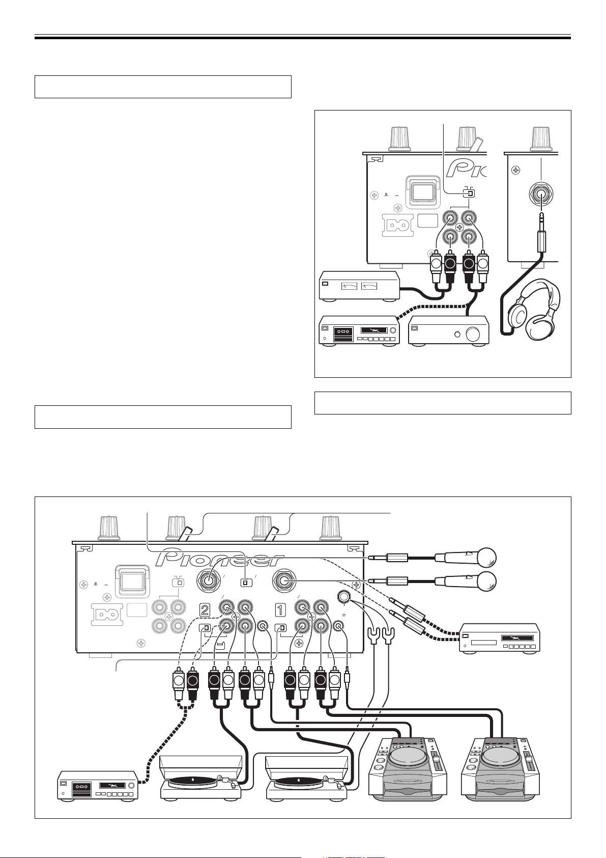
CONNECTING OUTPUTS
Master output
This unit is furnished with MASTER OUT 1 and MASTER OUT 2
output systems, both of which support the use of RCA plugs.
If the unit’s STEREO/MONO switch is set to [MONO], the master
output will be a monaural combination of L+R channels.
Headphones
The front panel PHONES jack can be used to connect headphones
with a Ø6.3 mm stereo phone plug.
STEREO/MONO switch
Front panel
Power amplifier
Cassette deck, etc.
(analog input recording
Power amplfier Headphones
component)
CONNECTING THE POWER CORD
Connect the power cord last.
÷ After completing all other connections, connect the accessory
power cord to the AC inlet on the back of the player, then connect
the plug to a standard wall outlet or to the auxiliary power outlet
of your amplifier.
÷ Use only the supplied power cord.
POWER
OFF
AC IN
PHONO/LINE switch
Note:
Set switch to [LINE]
except when using
an analog turntable
MIC/AUX switch
ON
MASTER
OUT
L
R
MONO STEREO
L R
Input selector switches
Microphone 2
MIC2 MIC1
AUX(R) AUX(L)
21
PHONO
L
LINE PHONO
R
AUXMIC
CD
LINE
CONTROL
LINE PHONO
PHONO
CD
LINE
SIGNAL
L
R
GND
R
CONTROL
Microphone 1
L
Electronic instrument,
LRLRLRLR
CD player, etc. (phone
plug connection)
Cassette deck, etc. Analog turntable Analog turntable DJ CD player DJ CD player
5
Page 6

NAMES AND FUNCTIONS OF PARTS
6
Page 7

NAMES AND FUNCTIONS OF PARTS
Beat effect section
15 BPM display
Displays the current track tempo as Beats Per Minute (BPM).
¶ The display flashes during BPM calculation and when BPM cannot
be calculated.
16 BPM measuring mode button/indicator (AUTO)
Each time the button is pressed, the BPM measuring mode alternates
as follows:
AUTO mode:
The AUTO button lights and the BPM is calculated automatically.
This is the default mode whenever power is first turned on.
TAP mode (manual input):
The AUTO button does not light, and BPM is input manually by using
the TAP button.
17 TAP button
The BPM is calculated from the intervals at which the TAP button is
struck. If the TAP button is tapped in the AUTO mode, the mode
automatically switches to the TAP mode (manual input).
18 Beat select buttons (BEAT/PITCH –, +)
+ (Beat up): Doubles the calculated BPM.
– (Beat down): Halves the calculated BPM.
¶ If one of the BEAT/PITCH buttons (–, +) is pressed while holding
the TAP button depressed, the BPM can be changed (40 to 999, in
1-step increments).
During in-loop sampler play, the loop play speed is changed.
+ (Beat up): Play speed becomes faster while button is pressed.
– (Beat down): Play speed becomes slower while button is pressed.
19 Beat select/bank buttons/indicators
(BEAT 1 (1/2), 2 (3/4), 4 (1/1), 8 (2/1), 16 (4/1) /
BANK)
Use to select the beat for synchronizing effects (P.11)
The selected button lights.
During in-loop sampler play, the buttons function as bank buttons to
record samples of the music (P. 12).
If the BEAT/BANK button is pressed while holding the ERASE
(BEAT/PITCH –) button depressed, the music sample recorded in the
BEAT/BANK button will be erased.
20 Effect selector (DELAY/ECHO/FILTER/FLANGER/
PHASER/ROBOT/ROLL/IN-LOOP SAMPLER)
Use to select desired type of effect (P. 10 to 12).
21 Effect channel selector
(CH. SELECT 1/2/MIC/MASTER)
Use to select the channel to which beat effects are applied (P. 11).
When [MIC] is selected, effects are applied to both microphone 1 and
microphone 2.
22 Effect parameter dial (LEVEL/DEPTH)
Adjusts the quantitative parameters for selected beat effect (P. 11 to
12)
23 Effect button/indicator (ON/OFF)
Sets selected beat effects ON/OFF (P. 11).
When effects are disabled (OFF), the button lights. When effects are
enabled (ON), the button flashes. Whenever power is first turned ON,
effects default to OFF.
26 Microphone equalizer control dial (EQ)
Use to adjust the tone of microphones 1 and 2. When rotated fully
clockwise, attenuation of low-range sound is maximized. When
rotated fully counterclockwise, attenuation of high-range sound is
maximized. (Adjustable range 0 dB to –12 dB)
27 Microphone function selector switch (MIC)
OFF:
No microphone sound is output.
ON:
Microphone sound is output normally.
TALK OVER:
Microphone sound is output; when sound is input to a connected
microphone, the TALK OVER function operates and all sound other
than that from the microphone is attenuated by 20 dB.
Headphones output section
28 Headphone cue button/indicator
(CH-1, CH-2, MASTER)
Press the button for the source you wish to monitor with
headphones. When a button is OFF, its indicator lights dimly; when
ON, the button indicator lights brightly (P. 8).
When the [ECHO] effect is selected, the effect is not applied to
headphone outputs if headphone cue buttons CH-1 or CH-2 are set to
ON.
29 Headphones level adjust dial (LEVEL)
Adjusts the output level of the headphones jack. (Adjustable range:
–∞ to 0 dB).
30 Headphones jack (PHONES)
Located on the unit’s front panel.
Microphone input control
24 Microphone 1 level control dial (MIC 1 LEVEL)
Use to adjust the volume of microphone 1. (Adjustable range –∞ to 0
dB)
When the connection panel’s MIC/AUX switch is set to [AUX], this
dial adjusts the sound volume for the left channel (AUX(L)).
25 Microphone 2 level control dial (MIC 2 LEVEL)
Use to adjust the volume of microphone 2. (Adjustable range –∞ to 0
dB)
When the connection panel’s MIC/AUX switch is set to [AUX], this
dial adjusts the sound volume for the right channel (AUX(R)).
7
Page 8

MIXER OPERATIONS (BASIC OPERATIONS)
MIXER OPERATIONS
BASIC OPERATIONS
8
Page 9

MIXER OPERATIONS (FADER START FUNCTION)
FADER START FUNCTION
By connecting the optional Pioneer DJ CD Player control cable, the
channel fader and cross fader can be used to start CD playback.
When the mixer’s channel fader lever or cross fader lever are moved,
the CD player is released from the pause mode and automatically –
and instantly – begins playback of the selected track. Also, when the
fader lever is returned to its original position, the CD player returns to
its cue point (back cue), thus allowing “sampler” type play.
Cross fader start play and back cue play
When the CD player assigned to channel 1 is set to standby at a cue
point, moving the cross fader lever from the right (2) side toward the
left (1) side, automatically starts play on the channel 1 CD player.
When the cross fader lever reaches the left (1) side, the CD player
assigned to channel 2 goes to back cue (returns to cue point). Also,
when the CD player assigned to channel 2 is set to standby at a cue
point, moving the cross fader lever from the left (1) side to the right
(2) side, automatically starts playback on the channel 2 CD player.
When the cross fader lever reaches the right (2) side, the channel 1
CD player goes to back cue (returns to cue point).
* The back cue is performed even if the input selector switch is not
set to [CD].
[Using the Channel Fader to Start Playback]
MASTER
BEAT EFFECTS
2
FADER
START
(CH-2)
53
2
FADER
START
(CH-1)
MIC
HEADPHONES
THRU/ /
1
[Using the Cross Fader to Start Playback]
MIC
1.Set the cross fader selector switch to the middle ( ) or the
right (
2. Press the FADER START button for the channel (1 to 2)
connected to the CD player you wish to control.
¶ The button for the selected channel lights.
3.Set the cross fader lever fully to the opposite side from the
channel you wish to start.
4.Set the CD player to the desired cue point, and engage cue
point standby.
¶ If a cue point has already been set, it is not necessary to set the
5.At the instant you wish to start playback, move the cross
fader lever.
¶ CD player begins playback.
¶ After playback has begun, if the cross fader lever is moved fully
* If the cross fader selector switch is set to [THRU], channel fader
operation is enabled, and the cross fader cannot be used to
control playback.
) position.
CD player to standby at the cue point.
to the side opposite from its start, the CD player assigned to the
opposite side channel will return to the cue point and enter
standby mode (back cue).
1. Set the cross fader selector switch to the left (THRU)
position.
2. Press the FADER START button for the channel (1 to 2)
connected to the CD player you wish to control.
¶ The button for the selected channel lights.
3.Set the channel fader lever to its lowest position.
4.Set the CD player to the desired cue point, and engage cue
point standby.
¶ If a cue point has already been set, it is not necessary to set the
CD player to standby at the cue point.
5. At the instant you wish to start playback, move the
channel fader lever.
¶ CD player begins playback.
¶ After playback has begun, if the channel fader lever is returned
to its minimum position, the CD player returns to the cue point
and reenters standby mode (back cue).
* If the cross fader selector switch is set to a position other than
[THRU], the cross fader control is enabled and channel fader
cannot be used for control.
9
Page 10

EFFECT FUNCTIONS (TYPES OF BEAT EFFECTS)
EFFECT FUNCTIONS
This unit is equipped with a total of 8 basic effects using beat effects
and in-loops linked to the BPM. By changing the parameters for each
effect, a wide variety of new effects can be produced. By using the
BEAT/BANK buttons to set the time parameters, an even wider
assortment of beat effects can be produced.
TYPES OF BEAT EFFECTS
1. DELAY (One repeat sound)
This function allows a delay sound with beat of 1/2, 3/4, 1/1, 2/1
or 4/1 to be added quickly and simply. For example, When a 1/2
beat delay sound is added, four beats become eight beats.
Also, by adding a 3/4 beat delay sound, the rhythm becomes
syncopated.
Example
Original
(4 beats)
1/2 delay
(8 beats)
4. FLANGER
In units of 1/1, 2/1, 4/1, 8/1 or 16/1 beat, 1 cycle of flanger effect
is produced quickly and easily.
Example
Short
delay
1 cycle = 1/1, 2/1, 4/1, 8/1 or 16/1 beat
5. PHASER
In units of 1/1, 2/1, 4/1, 8/1 or 16/1 beat, 1 cycle of phaser effect
is produced quickly and easily.
Example
Phase shift
1 cycle = 1/1, 2/1, 4/1, 8/1 or 16/1 beat
2. ECHO (Multiple repeat sounds)
This function allows an echo sound with beat of 1/2, 3/4, 1/1, 2/1
or 4/1 to be added quickly and simply.
For example, when a 1/1 beat echo sound is used to cutoff the
input sound, a sound in synch with the beat is repeated together
with fadeout.
Also, by adding a 1/1 beat echo to the microphone, the
microphone sound repeats in synch with the music beat.
If a 1/1 beat echo is applied to the vocal portion of a track, the
song takes on an effect reminiscent of a “round”.
Example
1 beat
Cuts input
sound
1 beat
3. FILTER
In units of 1/1, 2/1, 4/1, 8/1 or 16/1 beat, the filter frequency is
moved, greatly changing the sound coloration.
Example
6. ROBOT
Generates a sound effect resembling that produced by a robot.
7. ROLL
Sounds of 1/2, 3/4, 1/1, 2/1 or 4/1 beat are recorded and output
repetitively.
Example
Original
Effect ON
1/1 roll
Repeat
10
Frequency
1 cycle = 1/1, 2/1, 4/1, 8/1 or 16/1 beat
Page 11

EFFECT FUNCTIONS (PRODUCING BEAT EFFECTS/IN-LOOP SAMPLER)
PRODUCING BEAT EFFECTS
BEAT EFFECTS
BPM
AUTO
1
1
2
3
2
4
1
1
4
BEAT
2
8
1
4
16
1
BANK
BEAT
FLANGER
PHASER
FILTER
ECHO
DELAY
CH. SELECT
MIC
2
1
LEVEL/DEPTH
ON/OFF
Beat effects allow the instant setting of effect times in synch with the
BPM (beats per minute), thus allowing the production of a wide
variety of effects in synch with the current rhythm, even during live
performances.
1.Press the AUTO button to set the Beats Per Minute (BPM =
track tempo) measuring mode.
AUTO: The AUTO button lights, and the BPM of the input sound
TAP: The BPM is input manually by tapping on the TAP button.
¶ Whenever power is first turned ON, the function defaults to the
¶ In the event the track’s BPM cannot be detected automatically,
¶ The effective range in the AUTO mode is 70 to 180 BPM.
is measured automatically.
The AUTO button indicator does not light.
[AUTO] mode.
the display’s BPM counter will flash.
It may not be possible to measure some tracks accurately.
In this case, use the TAP mode for manual BPM input.
[Using the TAP Button for Manual BPM Input]
If the TAP button is tapped two times or more in synch
with beat (1/4 notes), the BPM will be recorded as the
average value recorded during that interval.
¶ When BPM mode is set to [AUTO], tapping the TAP button will
cause the BPM mode to change to the TAP mode, and the
interval at which the TAP button is pressed will be measured.
¶ When the BPM is set via the TAP button, the beat multiple
becomes “1/1” or “4/1” (depending on the effect selected),
and the time for 1 beat (1/4 notes) or 4 beats will be set as the
effect time.
[Using the BEAT/PITCH buttons for Manual BPM Input]
By pressing the BEAT/PITCH buttons (–, +) while holding
the TAP button depressed, the BPM can be changed.
¶ The BPM can be set from 40 to 999 in 1-step increments.
2. Set the effect selector to an effect other than [IN-LOOP
SAMPLER].
¶ See P. 10 regarding the various effects.
3.Set the effect channel selector to the channel you wish to
apply the effect to.
¶ If [MIC] is selected, the effect will be applied to both
microphone 1 and microphone 2.
TAP
ROBOT
MASTER
MAXMIN
PITCH
ROLL
IN-LOOP
SAMPLER
ERASE
1
AUTO
TAP
5
BEAT/PITCH –, +
BEAT/BANK
4
=1(1/2) / 2(3/4) / 4(1/1) / 8(2/1) / 16(4/1)
2
=DELAY / ECHO / FILTER /
FLANGER / PHASER /
ROBOT / ROLL
3
CH. SELECT
=1 / 2 / MIC / MASTER
6
LEVEL/DEPTH
ON/OFF
7
4.Press one of the BEAT/BANK buttons to select the beat to
which you wish to synchronize the effect.
¶ Values can be selected from [1/2, 3/4, 1/1, 2/1, 4/1] or [1, 2, 4, 8,
16]. (The multiple differs depending on the effect. See page 10
for details.)
¶ The selected button will light.
¶ The effect time corresponding to the beat’s multiple is set
automatically.
Example: When BPM=120
1/1 = 500 ms
1/2 = 250 ms
2/1 = 1 000 ms
5. Use the BEAT/PITCH buttons (–, +) to select the beat
multiple to which you wish to synchronize the effects.
¶ When [+] is selected, the beat calculated from the BPM is
doubled, and when [–] is pressed, the beat calculated from the
BPM is halved.
¶ When the time parameter lies within the range calculated from
the BPM, the BEAT/BANK button corresponding to that value
lights. When the parameter falls between two beat values, both
BEAT/BANK buttons will flash. When the values is less than 1/
2 (1), the 1/2(1) button will flash, and when greater than 4/1
(16), the 4/1(16) button will flash.
¶ During use of [DELAY], [ECHO], or [ROLL] effects, if the [–], [+]
buttons are used to shift the multiple, the “3/4” value will be
skipped. However, the 3/4 multiple can be selected by pressing
the 3/4 button directly.
6. Rotate the LEVEL/DEPTH dial to set the quantitative
parameter for the selected effect.
¶ See P. 12 for details regarding the effect of rotating the dial on
the parameter.
7.
Set the ON/OFF button to ON to enable the selected effect.
¶ Each time the button is pressed, the effect is toggled ON/OFF.
(Whenever power is first turned ON, the function defaults to
OFF).
¶ The ON/OFF button flashes when effects are ON.
IN-LOOP SAMPLER
BEAT EFFECTS
BPM
AUTO
1
1
2
3
2
4
1
1
4
BEAT
2
8
1
4
16
1
BANK
BEAT
FLANGER
PHASER
FILTER
ECHO
DELAY
CH. SELECT
MIC
2
1
TAP
ROBOT
MASTER
PITCH
ROLL
IN-LOOP
SAMPLER
ERASE
3
AUTO
TAP
ERASE
6
BEAT/PITCH –, +
5
8
1
2
=IN-LOOP SAMPLER
CH. SELECT
BEAT/BANK
=1 / 2 / MIC / MASTER
LEVEL/DEPTH
7
LEVEL/DEPTH
MAXMIN
ON/OFF
ON/OFF
4
This function detects the current track’s BPM, and 4 beat sources are
recorded in up to five memory banks, and played as loops in sync
with the current track’s BPM. Overlapped recording is also possible.
1.Set the effect selector to [IN-LOOP SAMPLER].
2.Set the effect channel selector to the channel you wish to
sample record.
3.Measure the BPM.
¶ Perform step 1 of the section “PRODUCING BEAT EFFECTS”
(P. 11).
4.Set the ON/OFF button to ON.
11
Page 12

EFFECT FUNCTIONS (IN-LOOP SAMPLER/EFFECT PARAMETERS)
5.At the point you wish to sample record, press one of the
non-lighted BEAT/BANK buttons.
¶ Lighted
¶ Recording begins automatically when the sound signal from
¶ When 4 beats of sound at the measured BPM have been
BEAT/BANK
cannot be used again unless their recorded contents are
erased.
CD player or other component is detected. During recording,
the
BEAT/BANK
standby, the button will flash slowly at intervals.
recorded, the
is performed.
buttons have already been recorded, and
button will flash quickly. During recording
BEAT/BANK
button flashes slowly and loop play
6. If the beat becomes unsynchronized, press one of the
BEAT/PITCH buttons (–, +) to resynchronize the timing of
the playback sample to the currently playing track.
¶ The playback speed increases while the [+] button is
depressed, and decreases while the [–] button is depressed.
7.Rotate the LEVEL/DEPTH dial to adjust the sound balance
between source and sample.
8. To stop loop playback, press the corresponding
BANK
button.
¶ The
BEAT/BANK
flashing to steadily lighted.
button indicator will change from slow
BEAT/
[To Playback a Recorded Sample]
1 Set the effect selector switch to [IN-LOOP SAMPLER].
2 Use the effect channel selector to choose the channel for
loop playback.
3 Set the ON/OFF button to ON.
4 Press the BEAT/BANK button containing the sample you
wish to play as a loop.
¶ The BEAT/BANK buttons with recorded samples are lighted.
¶ The selected button will flash slowly and loop play will begin.
5 If the beat becomes unsynchronized, press one of the
BEAT/PITCH buttons (–, +) to resynchronize the timing of
the playback sample to the currently playing track.
¶ The playback speed increases while the [+] button is
depressed, and decreases while the [–] button is depressed.
6 Rotate the LEVEL/DEPTH dial to adjust the sound balance
between source and sample.
7 To stop loop playback, press the corresponding
button.
BANK
¶ The
BEAT/BANK
button indicator will light steadily.
BEAT/
[Erasing a Recorded Sample]
1 Set the effect selector to [IN-LOOP SAMPLER].
2 While holding the ERASE (BEAT/PITCH –) button
depressed, press the
sample you wish to erase.
The BEAT/BANK buttons containing recorded samples are lighted.
¶ The indicator in the selected BEAT/BANK button will go out
and the sample will be erased.
8. IN-LOOP SAMPLER
This function allows you to store 4-beat sounds in up to 5
banks, then output them repeatedly.
Example
Bank 1
Present
track
BPM=125
BEAT/BANK
Repeat
button containing the
EFFECT PARAMETERS
12
Page 13

TROUBLESHOOTING
TROUBLESHOOTING
Incorrect operations are often mistaken for trouble and malfunctions. If you think there is something wrong with this component, check
the points below. Sometimes the trouble may originate from another component. Thus, also check the other electrical appliances also in
use.
If the trouble cannot be rectified even after checking the following items, contact your dealer or nearest PIONEER service center.
Symptom
No power
No sound, or sound volume is too
low.
Sound is distorted.
Cross fader doesn’t work.
Can’t perform fader start with CD
player.
Effects don’t work.
BPM can’t be measured.
Measured BPM value is incorrect.
The measured BPM value is
different from the value published
with the CD.
Possible Cause
÷ The power cord is not connected.
÷ Input selector switch is set incorrectly.
÷ PHONO/LINE input selector switch is set
incorrectly.
÷ Connection cables are connected
incorrectly, or connections are loose.
÷ Jacks or plugs are dirty.
÷ Master output level is too high.
÷ Input level is too high.
÷ Cross fader selector switch is set to
[THRU].
÷ The FADER START button is set to OFF.
÷ Rear panel CONTROL jack is not connected
to CD player.
÷ Only the rear panel CONTROL jack is
connected to the CD player.
÷ Effect channel selector (CH. SELECT)
setting is incorrect.
÷ Effect parameter adjust dial (LEVEL/
DEPTH) is set to [MIN].
÷ Input level is set too high, or too low.
÷ BPM may not be correctly measurable with
some tracks.
÷ Some differences may occur due to
differences in BPM detection methods.
Remedy
÷ Connect to power outlet.
÷ Set input selector to playback component.
÷ Set the PHONO/LINE input selector to the
component being played.
÷ Connect correctly.
÷ Clean soiled jacks/plugs before connecting.
÷ Adjust master output level (MASTER LEVEL)
dial.
÷ Adjust the TRIM dial so that the input level
approaches 0 dB on the channel level
indicator.
÷ Correctly set the switch to a setting other than
[THRU].
÷ Set the FADER START button to ON.
÷ Use a control cable to connect the CONTROL
jacks of DJM-400 and CD player.
÷ Connect both the CONTROL jacks and CD
input connectors.
÷ Correctly select the channel on which you
wish to apply effects.
÷ Adjust the effect parameter adjust dial.
÷ Adjust the TRIM dial.
÷ Strike the TAP button to set BPM manually.
÷ No remedy is necessary.
Static electricity or other external interference may cause the unit to malfunction. To restore normal operation, turn the power off and then
on again.
13
Page 14

SPECIFICATIONS
SPECIFICATIONS
1.General
Power source .............................................................. AC 120 V, 60 Hz
Power consumption ..................................................................... 13 W
Operating temperature ....................+5 °C to +35 °C (+41 °F to +95 °F)
Operating humidity .................... 5 % to 85 % (without condensation)
Weight ............................................................................3.2 kg (7.05 lb)
Maximum dimensions ................ 223 (W) × 304.7 (D) × 106.6 (H) mm
8-3/4 (W) × 12 (D) ×4-3/16 (H) in
2. Audio section
Sampling rate ............................................................................. 96 kHz
A/D, D/A converter ...................................................................... 24 bits
Frequency response
LINE ......................................................................... 20 Hz to 20 kHz
MIC .......................................................................... 20 Hz to 20 kHz
PHONO ......................................................... 20 Hz to 20 kHz (RIAA)
S/N ratio (at rated output)
LINE ......................................................................................... 97 dB
PHONO .................................................................................... 82 dB
MIC .......................................................................................... 78 dB
Distortion (LINE-MASTER OUT) ............................................... 0.007 %
Input level/ Impedance
PHONO ...................................................................... –52 dBu/47 kΩ
MIC 1, MIC 2 ............................................................. –52 dBu/47 kΩ
CD, LINE .................................................................... –12 dBu/47 kΩ
Output Level/Impedance
MASTER OUT ............................................................ +2 dBu/10 kΩ
PHONES ...................................................................... + 2 dBu/32 Ω
Crosstalk (LINE) ............................................................................ 78 dB
Channel equalizer response (Isolater)
HI..................................................................... +9 dB to –∞ (13 kHz)
MID .................................................................... +9 dB to –∞ (1 kHz)
LOW ................................................................... +9 dB to –∞ (70 Hz)
Microphone equalizer response
HI..............–12 dB (full counterclockwise) to 0 dB (center) (10 kHz)
LOW ..................... –12 dB (full clockwise) to 0 dB (center) (100 Hz)
3. Input/output connector systems
PHONO/LINE input connectors
RCA pin jacks .................................................................................. 2
CD input connectors
RCA pin jacks .................................................................................. 2
MIC/AUX input connectors
Phone jacks (Ø6.3 mm) .................................................................. 2
MASTER output connectors
RCA pin jacks .................................................................................. 2
PHONES connectors
Stereo phone jack (Ø6.3 mm) ........................................................ 1
CONTROL connectors
Mini-phone jacks (Ø3.5 mm) ..........................................................2
4. Accessories
Operating Instructions .........................................................................1
Power cord ...........................................................................................1
Warranty card ...................................................................................... 1
Specifications and appearance are subject to change without notice.
14
Page 15

BLOCK DIAGRAM
BLOCK DIAGRAM
[CH-1]
PHONO
/LINE
CD
[CH-2]
PHONO
/LINE
CD
[MIC/AUX]
MIC 1/
AUX L
MIC 2/
AUX R
CH-1
CH-2
MIC 1
MIC 2
BPM
detect
[CH1]
BPM
detect
[CH2]
MIC ON/OFF
Mono/Stereo
Convert
MIC ON/OFF Mono/Stereo Convert
MIC OFF/ON
MIC 1
MIC 2
BEAT EFFECTS
CH1
CH2
MIC
Master
RIAA
PHONO1/LINE1
PHONO
LINE
RIAA
PHONO2/LINE2
PHONO
LINE
MIC 1 LEVEL
MIC 1
AUX L
MIC 2 LEVEL
MIC 2
AUX R
3-Band
3-Band
MIC/AUX
Effect Processor Effect out
CH1
EQ
CH2
EQ
BEAT
EFFECTS
[CH1](pre)
BEAT
EFFECTS
[CH2](pre)
BPM
detect
[MIC]
L
R
L
R
CD1
CD2
CUE
Monitor
[CH1]
CH1 Level Meter
CH1 CUE
CUE
Monitor
[CH2]
CH2 Level Meter
CH2 CUE
2-Band
MIC
EQ
L
R
Mix Ratio
TRIM
TRIM
CH1 Fader Cross Fader
CH2 Fader
MIC out
ADC
ADC
ADC
BEAT
EFFECTS
[CH1](post)
CF assign
BEAT
EFFECTS
[CH2](post)
THRU
Cross Fader
BPM detect
CH1
CH2
MIC
Master
CH-1
CH-2
MIC 1
MIC 2
Master out
H.P out
DSP
DSP
Talk Over Master VR
Talk Over
Detection
Filter
BEAT
EFFECTS
[MIC]
BPM Counter Send to CPU
MASTER
CH-1
CH-2
BPM
detect
[Master]
H.P Mix
CH-1
ON
OFF
OFF
ON
ON
OFF
ON
[MASTER OUTPUTS]
DAC
[HEADPHONES]
DAC
CPU
SDRAM
BEAT
EFFECTS
[Master]
CH1 CUE
CH2 CUE
MASTER
OFF
OFF
ON
OFF
ON
ON
ON
L
R
L
R
L
R
CH1(Mono)+CH2(Mono)
CH1 CUE
CH2 CUE
Master CUE
Headphone CUE
CH-2
OFF
ON
OFF
ON
OFF
ON
ON
MUTE
MUTE
SWITCHES
INDICATORS
Master Level Meter
H.P Mix
Headphone out
L CH
CH1(L)
CH2(L)
Master(L)
CH1(L)+CH2(L)
CH1(Mono)
CH2(Mono)
MASTER
OUT 1
MASTER
OUT 2
PHONES
&
H.P VR
Master(R)
CH1(R)+CH2(R)
Master(Mono)
Master(Mono)
Master(Mono)
Master out
H.P out
H.P out L
H.P out R
R CH
CH1(R)
CH2(R)
15
Page 16

Should this product require service in the U.S.A. and you wish
to locate the nearest Pioneer Authorized Independent Service
Company, or if you wish to purchase replacement parts,
operating instructions, service manuals, or accessories, please
call the number shown below.
800 – 782 – 7210
Please do not ship your product to Pioneer without first calling
the Customer Support Division at the above listed number for
assistance.
PIONEER ELECTRONICS (USA), INC.
CUSTOMER SUPPORT DIVISION
Should this product require service in Canada, please contact a
Pioneer Canadian Authorized Dealer to locate the nearest Pioneer Authorized Service Company in Canada.
Alternatively, please contact the Customer Service Department
at the following address:
Pioneer Electronics of Canada, Inc.
300 Allstate Parkway
Markham, ON L3R OP2
(905) 479-4411
1 (877) 283-5901
P.O. BOX 1760, LONG BEACH,
CA 90801-1760, U.S.A.
For warranty information please see the Limited Warranty
sheet included with your product.
For warranty information please see the Limited Warranty
sheet included with your product.
PIONEER CORPORATION 4-1, Meguro 1-Chome, Meguro-ku, Tokyo 153-8654, Japan
PIONEER ELECTRONICS (USA) INC.
Multimedia and Mass Storage Division: 2265 East 220th Street, Long Beach, CA 90810, U.S.A. TEL: 800-444-OPTI (6784)
PIONEER ELECTRONICS OF CANADA, INC.
Industrial Products Department: 300 Allstate Parkway, Markham, Ontario L3R OP2, Canada TEL: 905-479-4411
Published by Pioneer Corporation.
Copyright © 2006 Pioneer Corporation.
All rights reserved.
Printed in <DRB1405-A><06A00000>
 Loading...