

Pioneer DEHP-9600-MP Service manual
PIONEER CORPORATION 4-1, Meguro 1-chome, Meguro-ku, Tokyo 153-8654, Japan
PIONEER ELECTRONICS (USA) INC. P.O. Box 1760, Long Beach, CA 90801-1760, U.S.A.
PIONEER EUROPE NV Haven 1087, Keetberglaan 1, 9120 Melsele, Belgium
PIONEER ELECTRONICS ASIACENTRE PTE. LTD. 253 Alexandra Road, #04-01, Singapore 159936
PIONEER CORPORATION 2004
ORDER NO.
CRT3192
DEH-P9600MP/XN/EW
MULTI-CD CONTROL DSP HIGH POWER CD/MP3/WMA PLAYER WITH RDS TUNER
DEH-P9600MP
This service manual should be used together with the following manual(s):
Model No. Order No. Mech.Module Remarks
CX-3098 CRT3179 S10WMAcode2 CD Mech. Module:Circuit Description, Mech. Description, Disassembly
/XN/EW
For details, refer to "Important symbols for good services".
K-ZZU.FEB. 2004 printed in Japan
1234
SAFETY INFORMATION
A
- CD Section Precaution
1. Before disassembling the unit, be sure to turn off
the power. Unplugging and plugging the connectors
during power-on mode may damage the ICs inside
the unit.
2. To protect the pickup unit from electrostatic discharge
during servicing, take an appropriate treatment
(shorting-solder) by referring to "the DISASSEMBLY"
on page 64.
3. After replacing the pickup unit, be sure to check the
grating. (See p.60.)
B
This service manual is intended for qualified service technicians; it is not meant for the casual do-it-yourselfer.
Qualified technicians have the necessary test equipment and tools, and have been trained to properly and safely
repair complex products such as those covered by this manual.
Improperly performed repairs can adversely affect the safety and reliability of the product and may void the warranty.
If you are not qualified to perform the repair of this product properly and safely, you should not risk trying to do so
and refer the repair to a qualified service technician.
1. Safety Precautions for those who Service this Unit.
• When checking or adjusting the emitting power of the laser diode exercise caution in order to get safe, reliable
results.
C
Caution:
1. During repair or tests, minimum distance of 13cm from the focus lens must be kept.
2. During repair or tests, do not view laser beam for 10 seconds or longer.
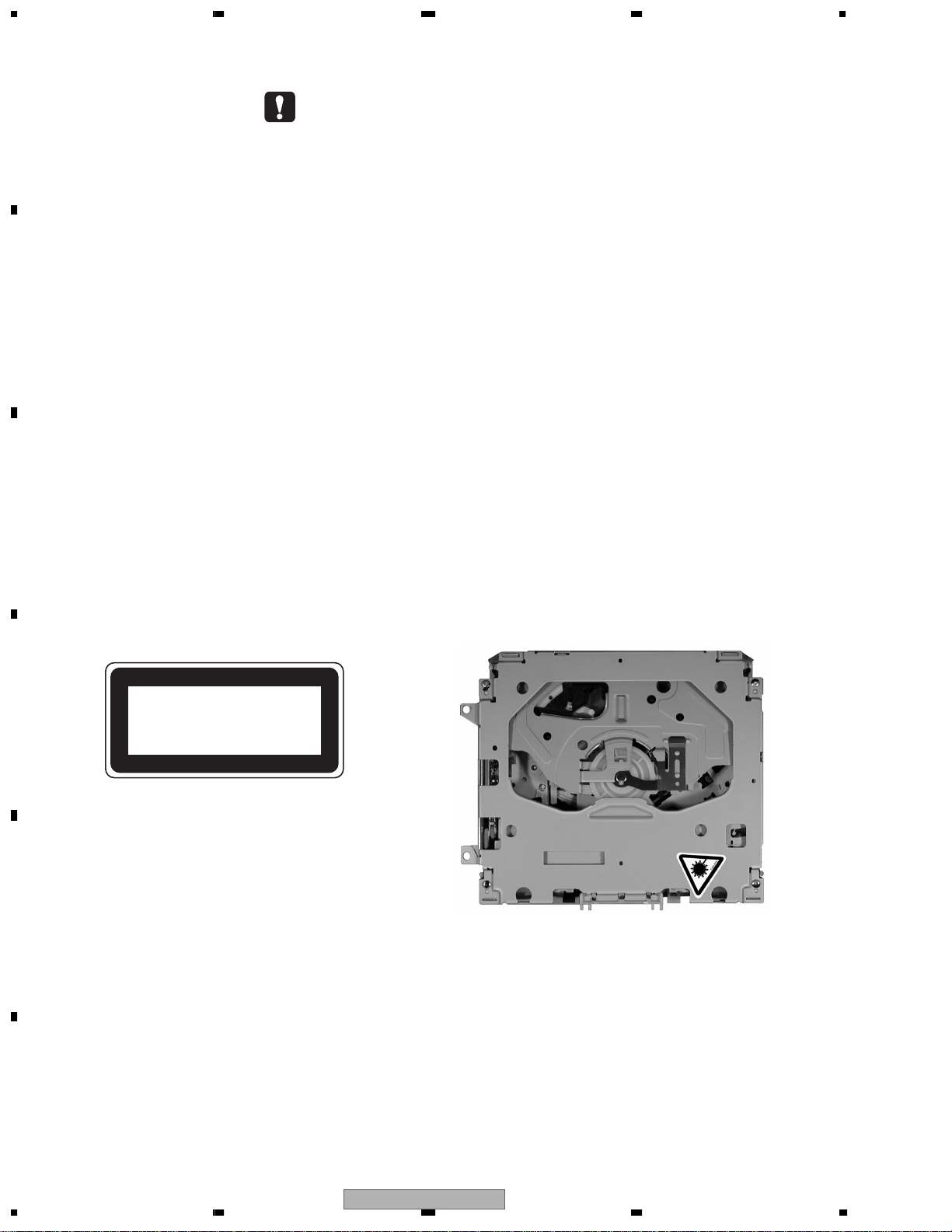
2. A “CLASS 1 LASER PRODUCT” label is affixed to the
bottom of the player.
D
CLASS 1
3. The triangular label is attached to the mechanism
unit frame.
LASER PRODUCT
E
4. Specifications of Laser Diode
Specifications of laser radiation fields to which human access is possible during service.
Wavelength = 800 nanometers
F
2
1234
DEH-P9600MP/XN/EW
5678
CAUTION
Danger of explosion if battery is incorrectly replaced.
Replaced only with the same or equivalent type recommended by the manufacture.
Discord used batteries according to the manufacture's instructions.
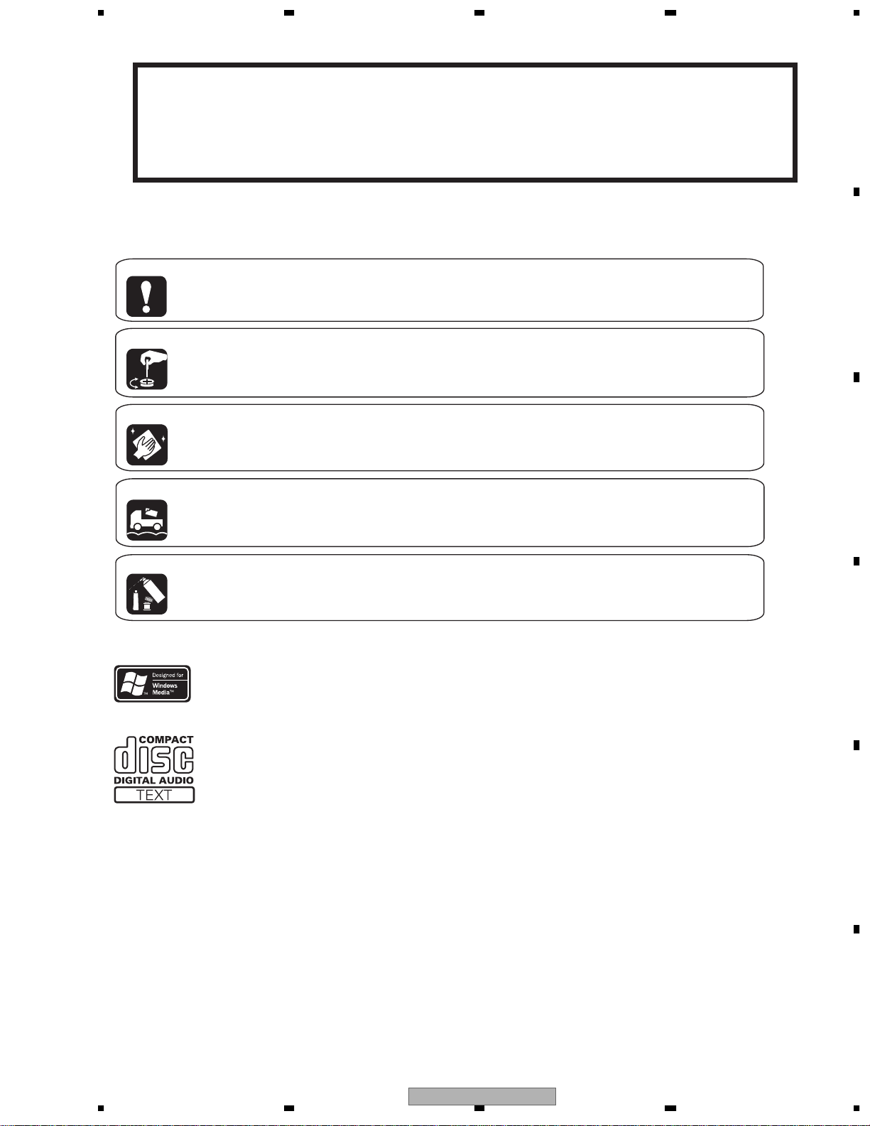
[ Important symbols for good services ]
In this manual, the symbols shown-below indicate that adjustments, settings or cleaning should be made securely.
When you find the procedures bearing any of the symbols, be sure to fulfill them:
1. Product safety
You should conform to the regulations governing the product (safety, radio and noise, and other regulations), and
should keep the safety during servicing by following the safety instructions described in this manual.
2. Adjustments
To keep the original performances of the product, optimum adjustments or specification confirmation is indispensable.
In accordance with the procedures or instructions described in this manual, adjustments should be performed.
3. Cleaning
For optical pickups, tape-deck heads, lenses and mirrors used in projection monitors, and other parts requiring cleaning,
proper cleaning should be performed to restore their performances.
4. Shipping mode and shipping screws
A
B
C
To protect the product from damages or failures that may be caused during transit, the shipping mode should be set or
the shipping screws should be installed before shipping out in accordance with this manual, if necessary.
5. Lubricants, glues, and replacement parts
Appropriately applying grease or glue can maintain the product performances. But improper lubrication or applying
glue may lead to failures or troubles in the product. By following the instructions in this manual, be sure to apply the
prescribed grease or glue to proper portions by the appropriate amount.For replacement parts or tools, the prescribed
ones should be used.
D
E
56
DEH-P9600MP/XN/EW
F
7
8
3

1234
CONTENTS
SAFETY INFORMATION.....................................................................................................................................2
A
B
C
D
1. SPECIFICATIONS............................................................................................................................................ 5
2. EXPLODED VIEWS AND PARTS LIST............................................................................................................8
2.1 PACKING ................................................................................................................................................... 8
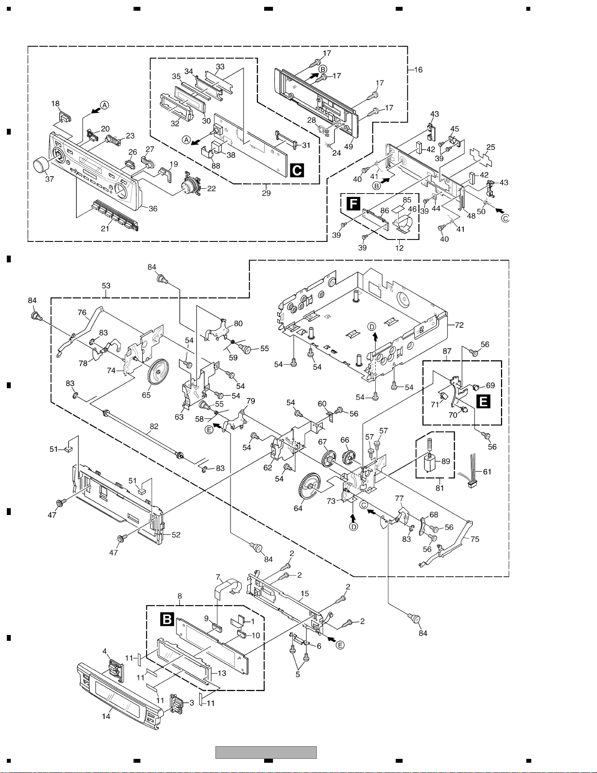
2.2 EXTERIOR(1) .......................................................................................................................................... 10
2.3 EXTERIOR(2) .......................................................................................................................................... 12
2.4 CD MECHANISM MODULE.....................................................................................................................14
3. BLOCK DIAGRAM AND SCHEMATIC DIAGRAM..........................................................................................16
3.1 BLOCK DIAGRAM................................................................................................................................... 16
3.2 OVERALL CONNECTION DIAGRAM(GUIDE PAGE).............................................................................. 18
3.3 KEYBOARD UNIT(OEL).......................................................................................................................... 24
3.4 KEYBOARD UNIT(LCD).......................................................................................................................... 26
3.5 CD MECHANISM MODULE(GUIDE PAGE)............................................................................................28
4. PCB CONNECTION DIAGRAM .....................................................................................................................38
4.1 TUNER AMP UNIT...................................................................................................................................38
4.2 KEYBOARD UNIT(OEL).......................................................................................................................... 42
4.3 KEYBOARD UNIT(LCD).......................................................................................................................... 43
4.4 CD MECHANISM MODULE.....................................................................................................................44
4.5 SWITCH PCB .......................................................................................................................................... 46
4.6 CONNECTOR PCB..................................................................................................................................47
5. ELECTRICAL PARTS LIST ............................................................................................................................48
6. ADJUSTMENT ............................................................................................................................................... 57
6.1 JIG CONNECTION DIAGRAM.................................................................................................................57
6.2 CD ADJUSTMENT................................................................................................................................... 58
6.3 CHECKING THE GRATING AFTER CHANGING THE PICKUP UNIT .................................................... 60
6.4 ERROR MODE ........................................................................................................................................ 62
6.5 FREQUENCY CHECK FOR CLOCK.......................................................................................................63
6.6 OEL SCREENSAVER STUDIO IKA TO LKD APPLICATION : GGV1168................................................63
7. GENERAL INFORMATION............................................................................................................................. 64
7.1 DIAGNOSIS............................................................................................................................................. 64
7.1.1 DISASSEMBLY.....................................................................................................................................64
7.1.2 CONNECTOR FUNCTION DESCRIPTION.......................................................................................... 72
7.2 PARTS...................................................................................................................................................... 73
7.2.1 IC .......................................................................................................................................................... 73
7.2.2 DISPLAY ............................................................................................................................................... 87
7.3 OPERATIONAL FLOW CHART...............................................................................................................88
7.4 CLEANING............................................................................................................................................... 89
8. OPERATIONS ................................................................................................................................................90
E
F
4
1234
DEH-P9600MP/XN/EW
5678
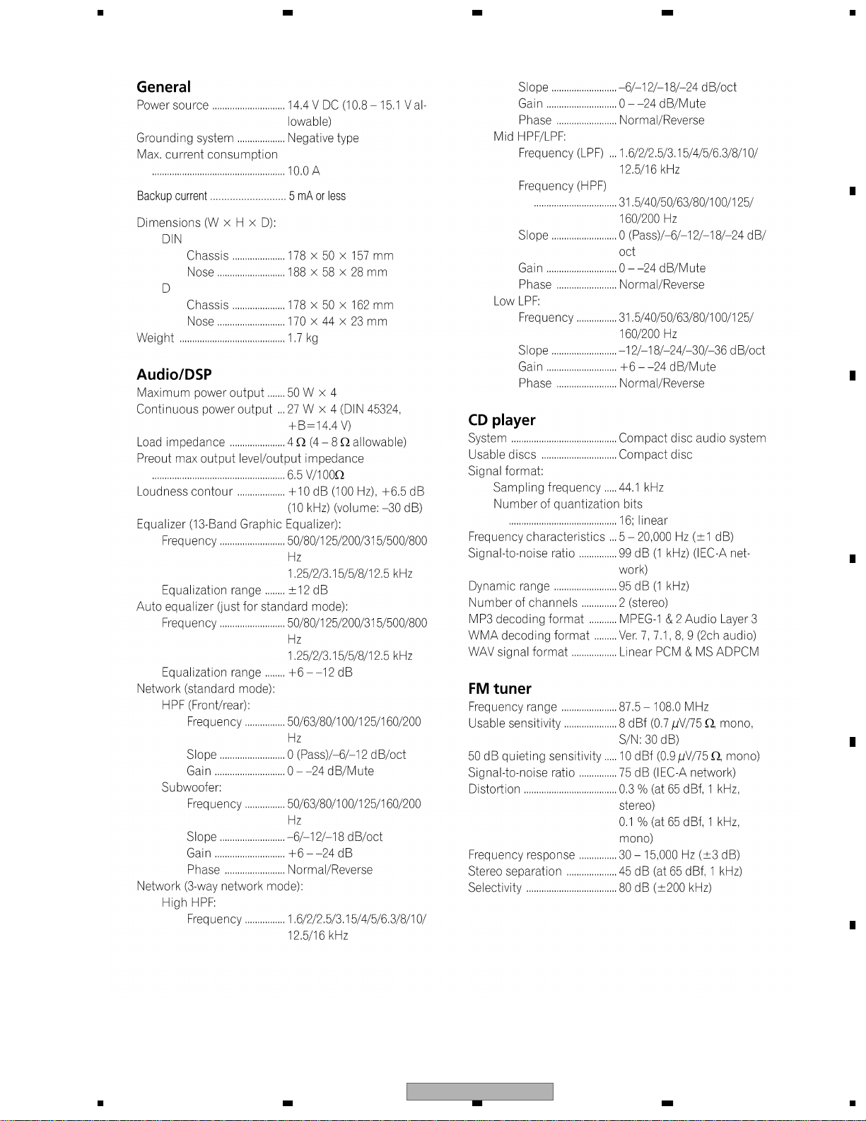
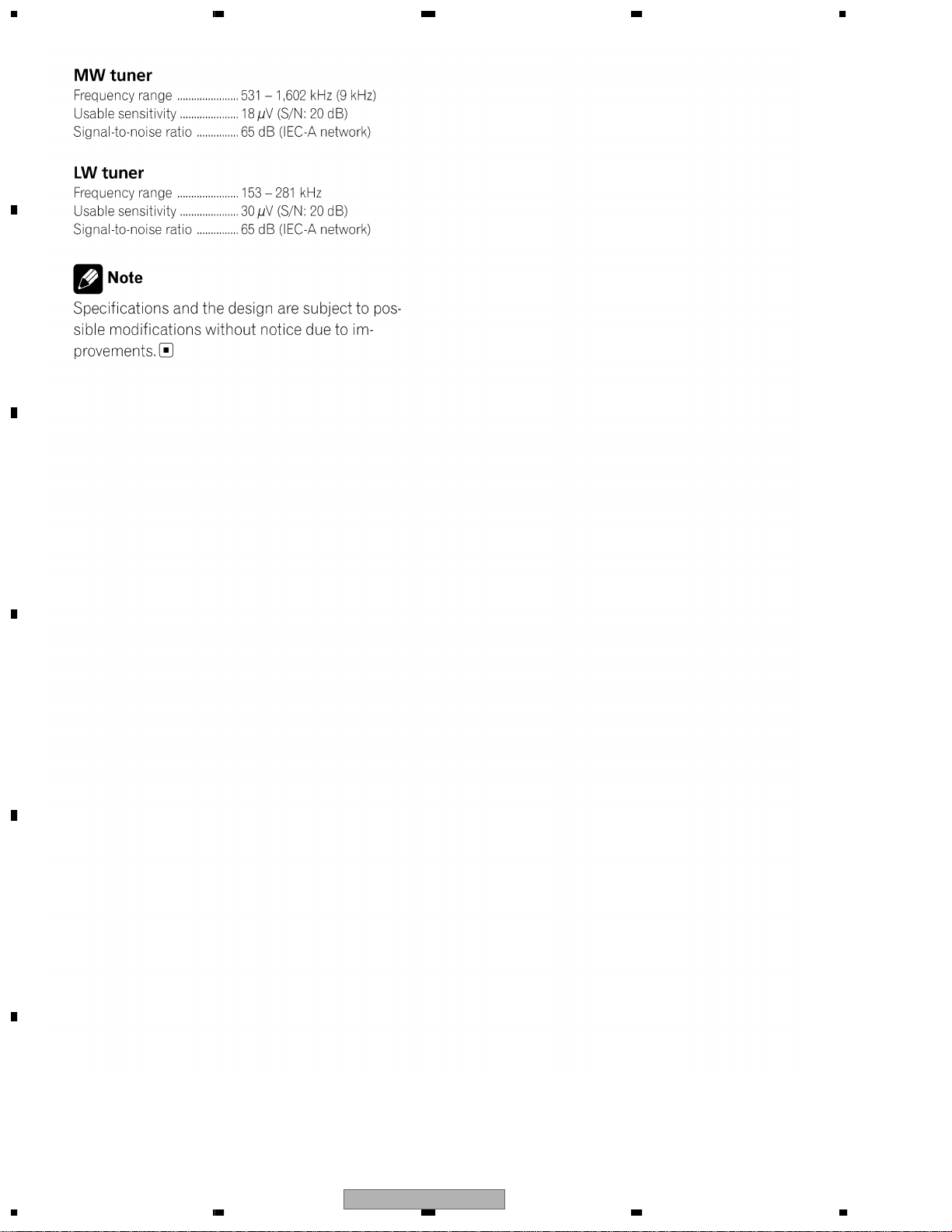
1. SPECIFICATIONS
A
B
C
D
E
56
DEH-P9600MP/XN/EW
F
7
8
5
1234
A
B
C
D
E
F
6
1234
DEH-P9600MP/XN/EW

5678
A
B
C
D
E
56
DEH-P9600MP/XN/EW
F
7
8
7
N
1234
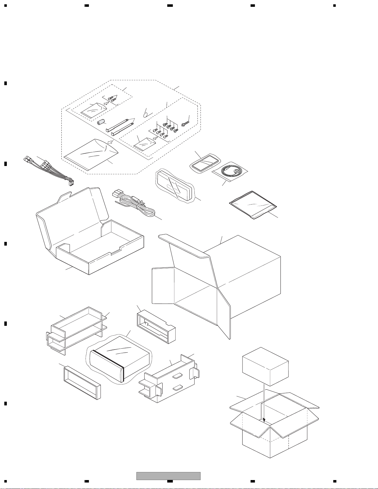
2. EXPLODED VIEWS AND PARTS LIST
OTES : • Parts marked by " * " are generally unavailable because they are not in our Master Spare Parts List.
A
• Screw adjacent to mark on the product are used for disassembly.
"
• For the applying amount of lobricants or glue, follow the instructions in this manual.
(In the case of no amount instructions,apply as you think it appropriate.)
2.1 PACKING
22
27
3
25
21
13
12
55
6
7
B
24
C
9
10
26
4
8
23
2
15
14
D
19
17
E
20
18
11
18
17
16
1
F
8
1234
DEH-P9600MP/XN/EW
5678
PACKING SECTION PARTS LIST
Mark No. Description Part No.
1-1 Owner's Manual CRD3813
1-2 Owner's Manual CRD3814
1-3 Owner's Manual CRD3815
1-4 Installation Manual CRD3816
* 1-5 Passport CRY1013
* 1-6 Warranty Card CRY1157
1-7 Polyethylene Bag CEG1116
* 1-8 Caution Card CRP1309
2 Cord Assy CDE6562
3 Accessory Assy CEA4111
4 Spring CBH1650
5 Screw Assy CEA4117
6 Screw BPZ20P060FZK
* 7 Polyethylene Bag CEG-127
8 Handle CNC5395
9 Bush CNV3930
* 10 Polyethylene Bag CEG-158
11 Polyethylene Bag CEG1088
Mark
No. Description Part No.
12 Case Assy CXB8574
13 Microphone Assy CPM1054
14 Sub Carton CHA3258
15 Carton CHG5202
16 Contain Box CHL5202
17 Protector CHP2538
18 Protector CHP2539
19 Protector CHP2541
20 Protector CHP2546
21 Remote Control Unit CXC2665
22 Screw Assy CEA4114
23 Screw BMZ50P060FTC
24 Cord Assy CDE7436
25 Screw CBA1650
* 26 Polyethylene Bag CEG-127
27 Screw CMZ50P060FTC
A
B
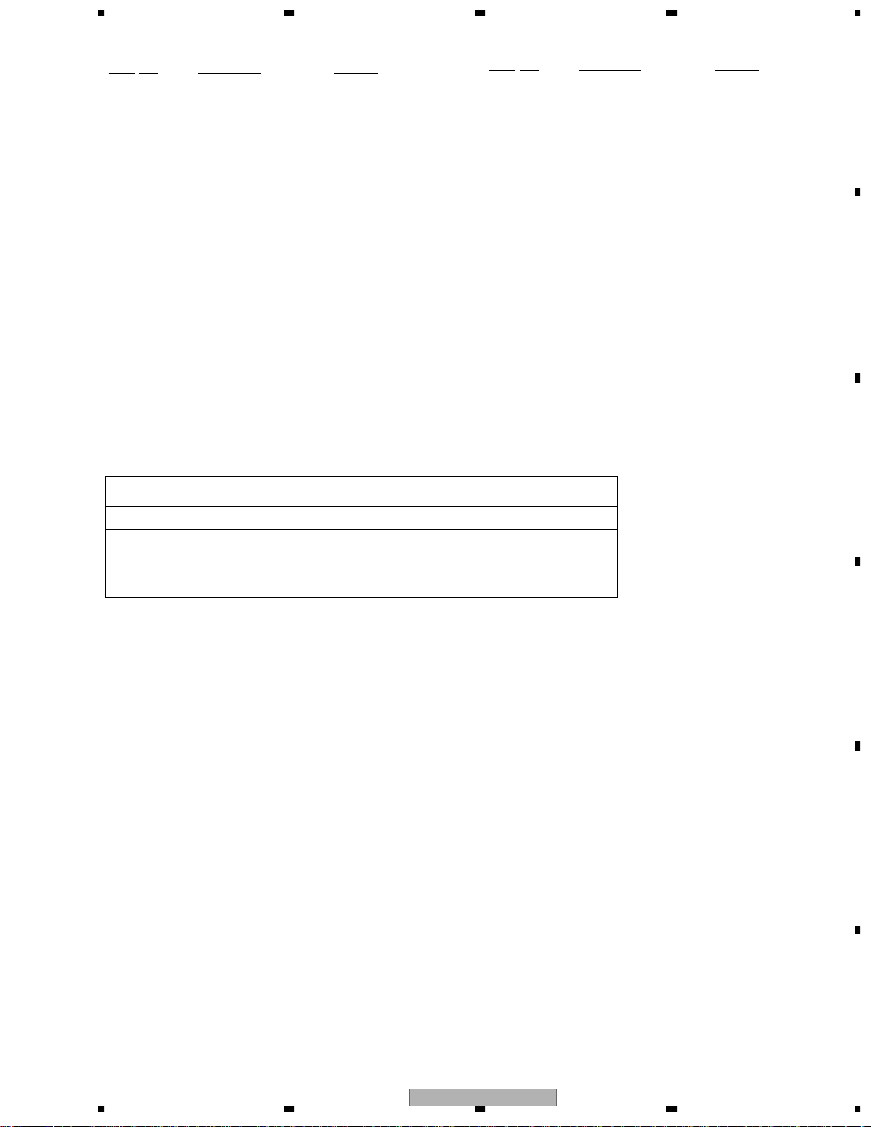
Owner's Manual,Installation Manual
Part No. Language
CRD3813 English,Spanish
CRD3814 German,French
CRD3815 Italian,Dutch
CRD3816 English,Spanish,German,French,Italian,Dutch
C
D
E
56
DEH-P9600MP/XN/EW
F
7
8
9
1234
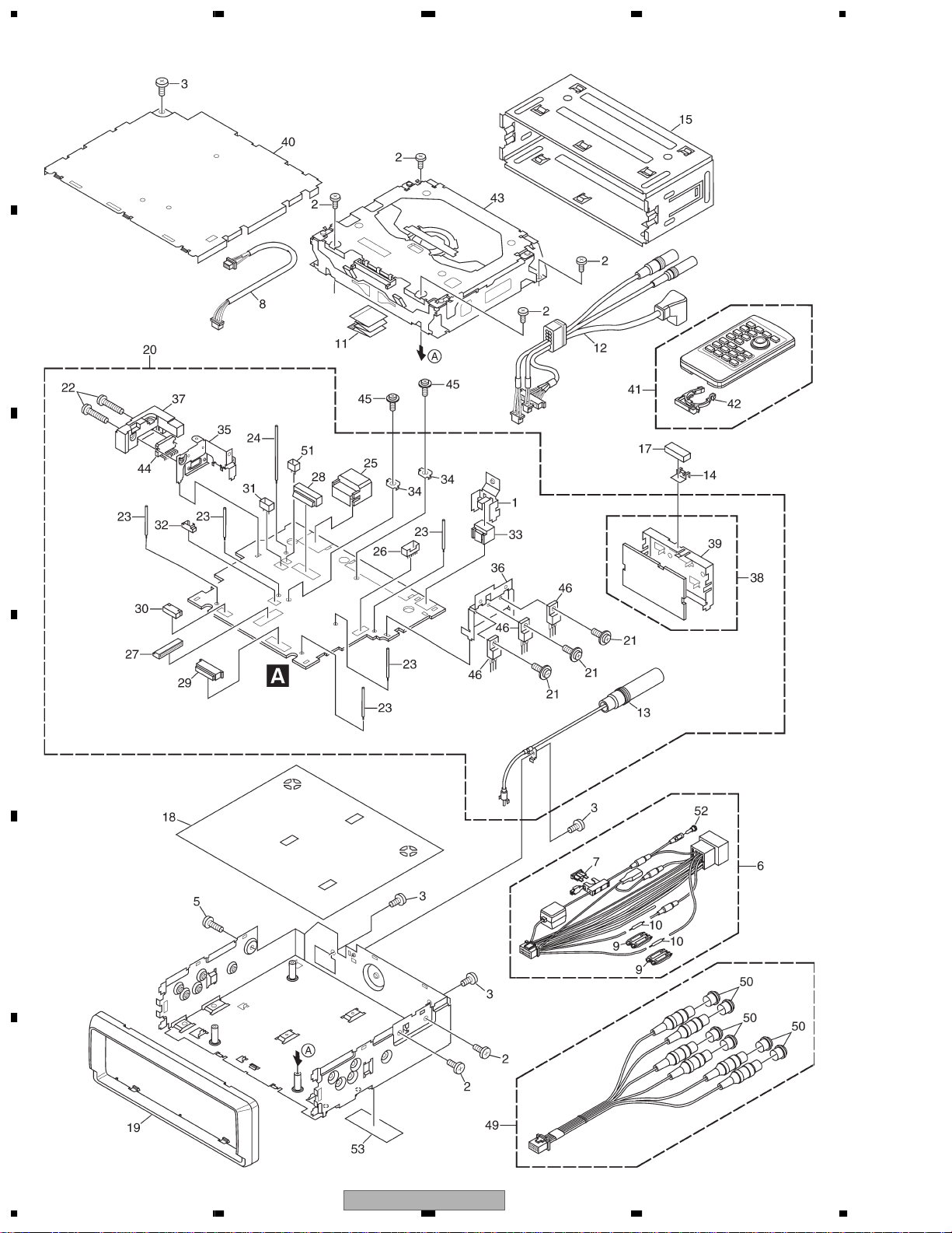
2.2 EXTERIOR(1)
A
B
C
D
E
F
10
1234
DEH-P9600MP/XN/EW

5678
EXTERIOR(1) SECTION PARTS LIST
Mark No. Description Part No.
1 Holder CND1979
2 Screw BSZ26P060FTC
3 Screw BSZ30P050FTC
4 •••••
5 Screw BSZ30P160FTC
6 Cord Assy CDE6562
7 Fuse(10A) CEK1136
8 Cord Assy CDE7439
9 Cap CNS1472
10 Resistor RS1/2PMF102J
No. Description Part No.
Mark
51 Plug(CN761) CKS1035
52 Pin CKX-003
53 Lavel VRW-329
A
11 Flat Cable CDE7440
12 Cord Assy CDE7433
13 Antenna Cable(CN401) CDH1336
14 Holder CNC6469
15 Holder CNC8659
16 •••••
17 Cushion CNM8890
18 Insulator CNM8590
19 Panel CNS6863
20 Tuner Amp Unit CWM9184
21 Screw ASZ26P080FTC
22 Screw BMZ26P140FTC
23 Clamper CEF1035
24 Clamper CEF1036
25 Plug(CN981) CKM1278
26 Plug(CN811) CKS-787
27 Connector(CN701) CKS3837
* 28 Plug(CN101) CKS1058
29 Connector(CN872) CKS1082
* 30 Connector(CN871) CKS2211
B
C
D
31 Connector(CN771) CKS1036
32 Connector(CN703) CKS3126
33 Connector(CN351) CKM1389
34 Holder CNC5399
35 Holder CNC9711
36 Holder CNC9713
37 Heat Sink CNR1615
38 FM/AM Tuner Unit CWE1645
39 Holder CND1054
40 Case Unit CXB8524
41 Remote Control Assy CXC2665
42 Cover CZN5357
43 CD Mechanism Module(S10WMACODE2)CXK5676
44 IC(IC301) PAL007A
45 Screw ISS26P055FTC
46 Transistor(Q742,901,921) 2SD2396
47 •••••
48 •••••
49 Cord Assy CDE7436
50 Cap CNV6727
DEH-P9600MP/XN/EW
56
E
F
7
8
11
1234
2.3 EXTERIOR(2)
A
B
C
D
E
F
12
1234
DEH-P9600MP/XN/EW

5678
EXTERIOR(2) SECTION PARTS LIST
Mark No. Description Part No.
1 Cable CDE7441
2 Screw BPZ20P080FZK
3 Button(AUDIO,FUNC) CAC8297
4 Button(ENT,DISP) CAC8298
5 Screw(M2x2) CBA1633
6 Holder CNC9800
7 Flexible PCB CNP6498
8 Keyboard Unit(OEL) CWM9191
9 Connector(CN1801) CKS4175
10 Connector(CN1802) CKS4792
11 Spacer CNM8982
12 PCB Assy(Service) CXX1799
13 OEL Module MXK8200
14 Grille Unit CXC2401
15 Case Unit CXC2406
16 Detach Grille Assy CXC3178
17 Screw BPZ20P080FZK
18 Button(EJECT) CAC8319
19 Button(OPEN) CAC8320
20 Button(TA) CAC8323
21 Button(1-6) CAC8317
22 Button Assy(CROSS) CXC3687
23 Button Unit(EQ) CXC2450
24 Spring CBH2543
25 Insulator CNM8897
26 Button(TEXT) CAC8324
27 Button Unit(BAND) CXC2451
28 Arm CNV6963
29 Keyboard Unit(LCD) CWM9194
30 LCD(LCD1901) CAW1704
31 Connector(CN1901) CKS4549
32 Holder CNC9648
33 Sheet CNM7512
34 Lighting Conductor CNV6914
35 Connector CNV6915
36 Grille Unit CXC2452
37 Knob Unit CXC3686
38 Jack(CN1902) CKN1016
39 Screw(M2x2) CBA1633
40 Screw CBA1561
No. Description Part No.
Mark
51 Cushion CNM8894
52 Panel Unit CXB7953
53 Drive Unit CXC2514
54 Screw BMZ26P040FTC
55 Screw(M2x1.4) CBA1757
56 Screw(M2x2) CBA1633
57 Screw JFZ20P030FTC
58 Spring CBH2752
59 Spring CBH2753
60 Spring CBL1658
61 Cord CDE7587
62 Holder CND2244
63 Holder CND2245
64 Gear CNV8087
65 Gear CNV8088
66 Gear CNV8090
67 Gear CNV8091
68 Lever CNV8092
69 Switch(S951) CSN1051
70 Spring Switch(S952) CSN1052
71 Switch(S953) CSN1058
72 Chassis Unit CXC2454
73 Holder Unit CXC3023
74 Holder Unit CXC3024
75 Arm Unit CXC3025
76 Arm Unit CXC3026
77 Arm Unit CXC3027
78 Arm Unit CXC3028
79 Arm Unit CXC3029
80 Arm Unit CXC3030
81 Motor Unit(M951) CXC3190
82 Gear Unit CXC3094
83 Washer YE15FTC
84 Screw(M2x1.5) CBA1559
85 Sheet CNM7839
86 PCB CNX3607
87 Switch Unit CWS1370
88 Holder CND1971
89 Motor CXM1217
A
B
C
D
E
41 Spring CBH2530
42 Cushion CNM8895
43 Arm CNV6962
44 Guide CNV6968
45 Guide CNV6967
46 Flexible PCB CNP7913
47 Screw ISS26P055FTC
48 Case Unit CXB7968
49 Cover Unit CXC2453
50 Spring CBH2545
56
DEH-P9600MP/XN/EW
F
7
8
13
1234
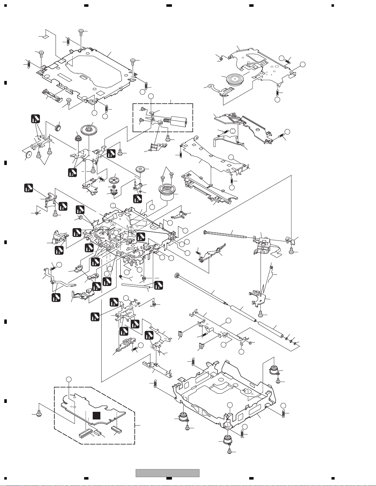
2.4 CD MECHANISM MODULE
42
A
13
5
13
5
34
81
15
5
22
E
F
93
13
A
44
B
5
B
1
54
C
52
53
13
D
86
86
82
83
4
37
71
4
29
51
1
73
50
72
10
1
I
76
B
55
4
36
4
1
18
2
24
47
7
C
64
2
1
61
2
M
1
23
87
75
E
63
57
62
58
1
G
L
1
N
R
1
1
2
1
40
56
D
O
16
P
1
33
1
P
19
J
12
3
20
39
1
69
30
2
21
M
D
79
2
1GEM1024
2GEM1045
3GEM1035
E
92
26
G
68
28
I
H
28
45
J
38
23
K
59
49
F
Q
A
27
H
77
90
48
8
67
17
78
25
70
60
80
N
L
K
43
46
6
60
11
89
10
14
74
R
31
41
85
C
91
F
D
3
94
65
1
2
85
66
35
O
31
Q
14
85
14
DEH-P9600MP/XN/EW
1234

5678
CD MECHANISM MODULE SECTION PARTS LIST
Mark No. Description Part No.
1 CD Core Unit(S10WMACODE2)CWX2953
2 Connector(CN101) CKS4182
3 Connector(CN901) CKS4017
4 Screw BMZ20P035FTC
5 Screw BSZ20P040FTC
6 Screw(M2x4) CBA1362
7 Screw(M2x3) CBA1511
8 Screw(M2x3) CBA1527
9 •••••
10 Washer CBF1038
11 Washer CBF1060
12 Spring CBH2390
13 Spring CBH2606
14 Spring CBH2607
15 Spring CBH2608
16 Spring CBH2609
17 Spring CBH2610
18 Spring CBH2735
19 Spring CBH2612
20 Spring CBH2613
21 Spring CBH2614
22 Spring CBH2615
23 Spring CBH2616
24 Spring CBH2617
25 Spring CBH2620
26 Spring CBH2621
27 Spring CBH2641
28 Spring CBH2642
29 Spring CBH2643
30 Spring CBH2659
31 Spring CBH2688
32 •••••
33 Shaft CLA4441
34 Frame CNC9962
35 Frame CNC9963
36 Bracket CNC9966
37 Bracket CND1895
38 Arm CNC9968
39 Arm CND1909
40 Lever CND2032
41 Lever CNC9984
42 Sheet CNM8134
43 Collar CNV7798
44 Guide CNV7799
45 Arm CNV7800
No. Description Part No.
Mark
51 Gear CNV7208
52 Gear CNV7209
53 Gear CNV7210
54 Gear CNV7211
55 Gear CNV7212
56 Rack CNV7214
57 Arm CNV7215
58 Arm CNV7216
59 Guide CNV7217
60 Roller CNV7218
61 Gear CNV7219
62 Arm CNV7221
63 Arm CNV7220
64 Arm CNV7222
65 Damper CNV7313
66 Damper CNV7314
67 Arm CNV7341
68 Arm CNV7342
69 Guide CNV7360
70 Guide CNV7361
71 Holder CNV7437
72 Arm CNV7805
73 Gear CNV7595
74 Damper CNV7618
75 Motor Unit(M1) CXB6007
76 Chassis Unit CXC2318
77 Screw Unit CXB8729
78 Gear Unit CXC2397
79 Arm Unit CXC2316
80 Arm CND1896
81 Arm CND1894
82 Motor Unit(M2) CXB8933
83 Bracket CNC9985
84 •••••
85 Screw(M2x5) EBA1028
86 Screw JFZ20P020FTC
87 Screw JGZ17P022FTC
88 •••••
89 Washer YE20FTC
90 Pickup Unit(P10)(Service) CXX1641
91 Screw IMS26P030FTC
92 Spring CBL1635
93 Clamper CNV7197
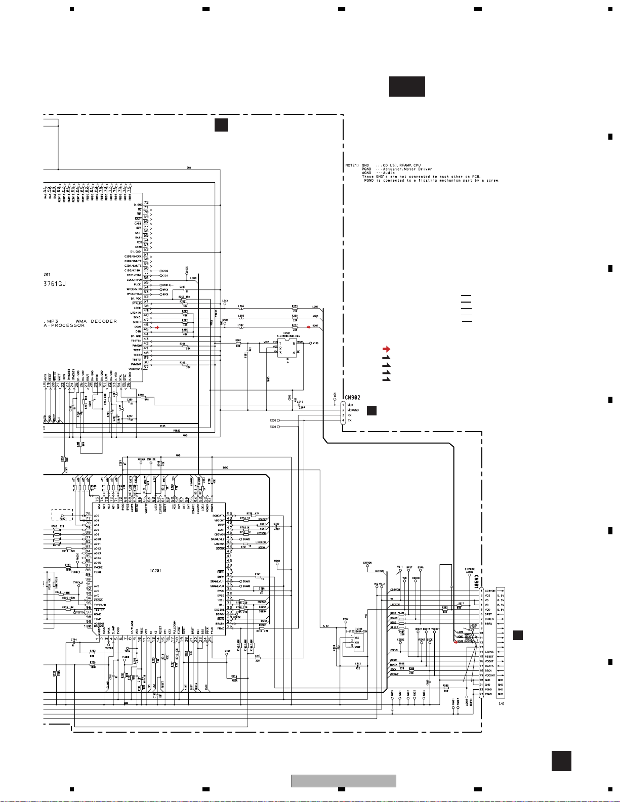
94 Connector(CN902) CKS2193
A
B
C
D
E
46 Rack CNV7199
47 Holder CNV7201
48 Holder CNV7202
49 Arm CNV7203
50 Gear CNV7207
56
DEH-P9600MP/XN/EW
F
7
8
15
1
X
P
N
3
L
2
8
3
8
1
8
1
8
1234
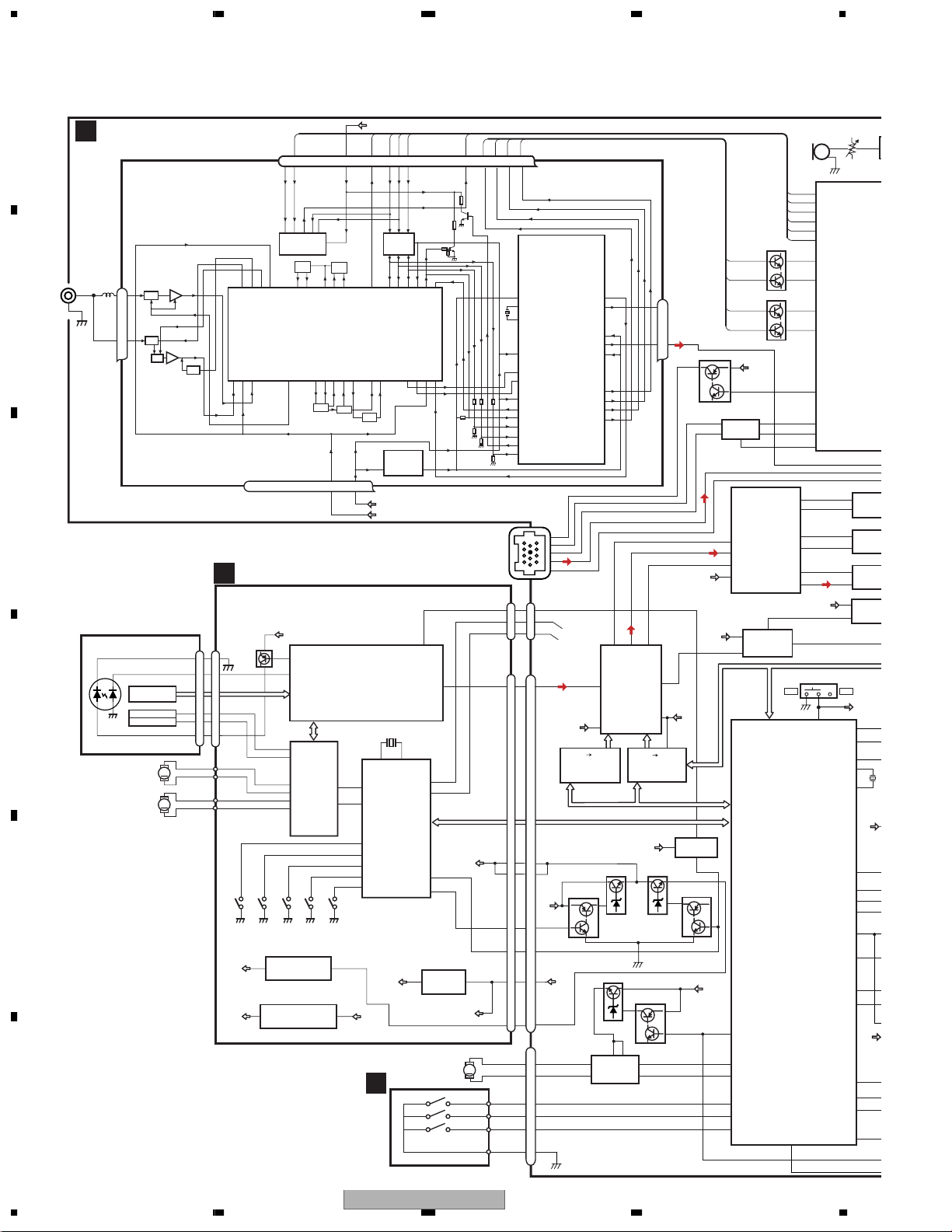
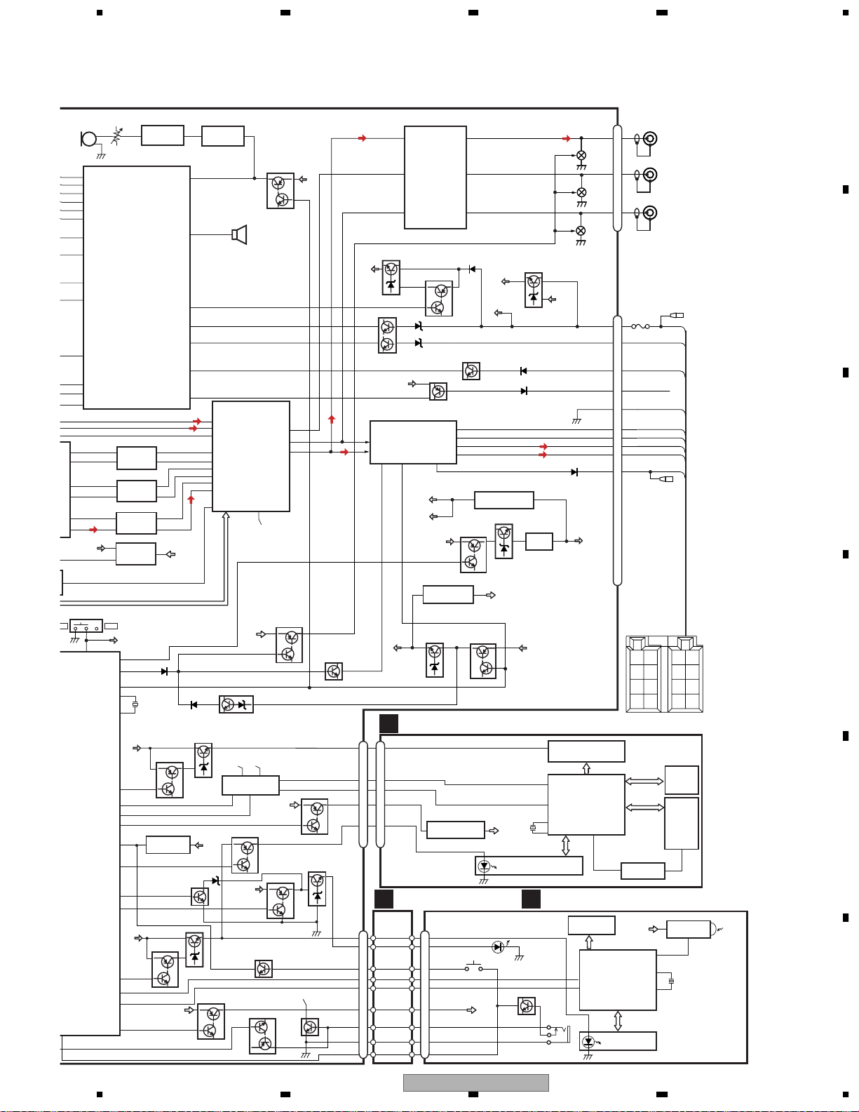
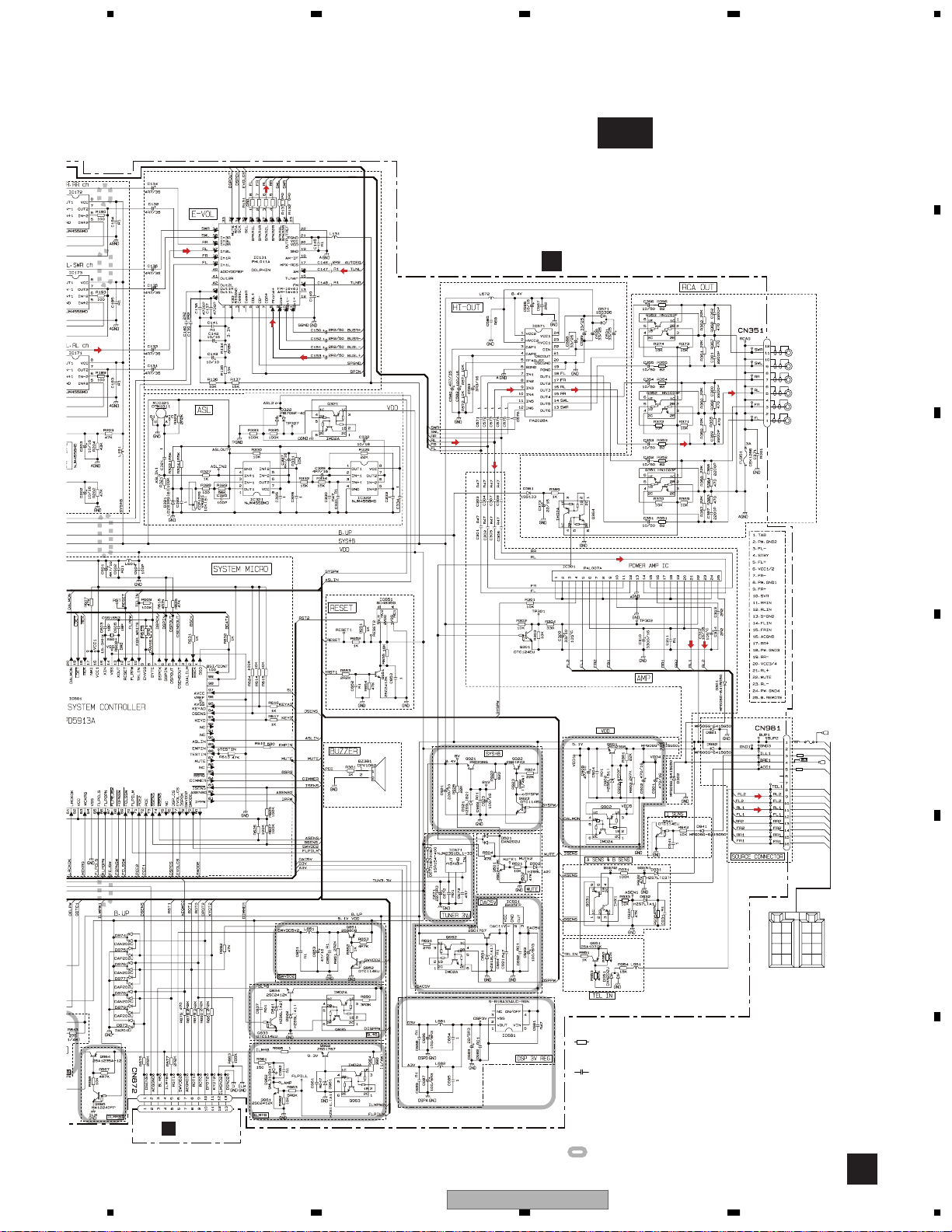
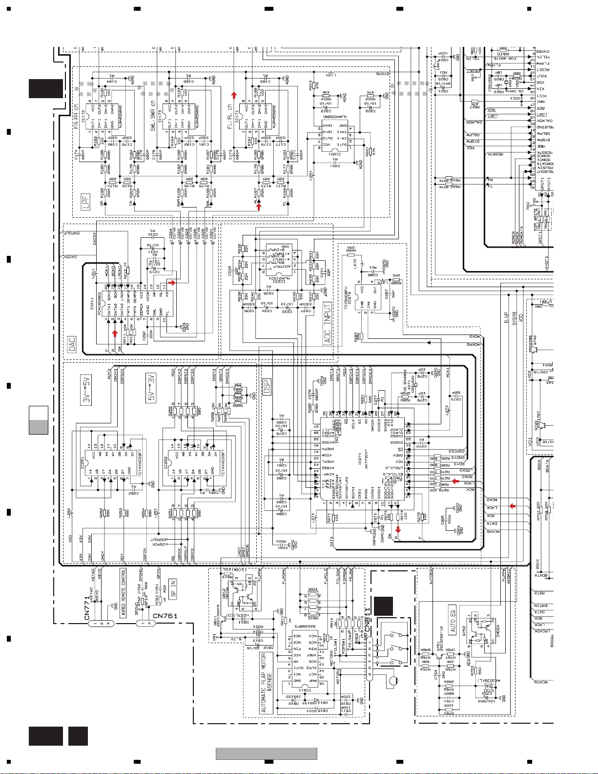
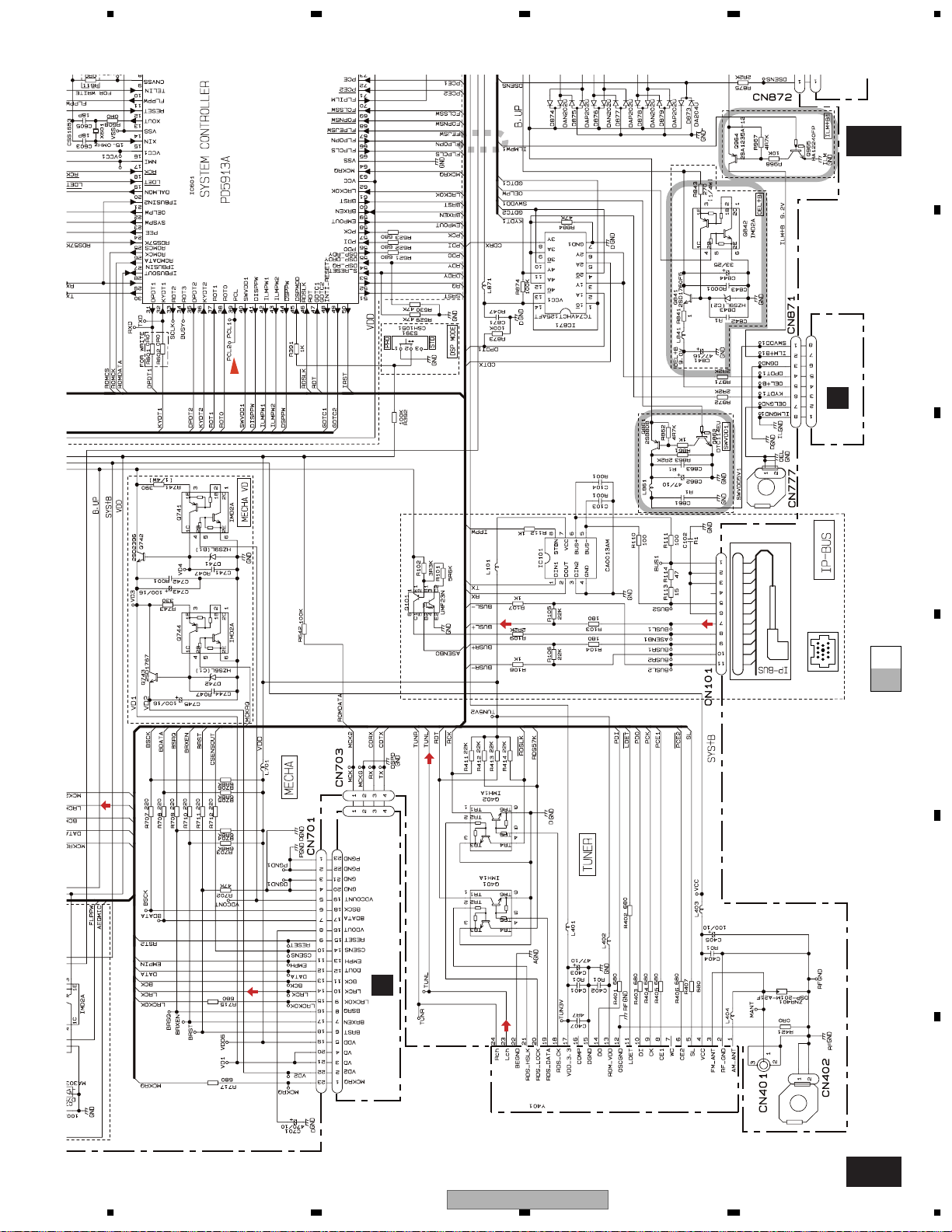
3. BLOCK DIAGRAM AND SCHEMATIC DIAGRAM
3.1 BLOCK DIAGRAM
A
TUNER AMP UNIT
A
7 6 13 5 10 9 8 11 14 18 19 20 21
WC
CE2
IC 3 EEPROM
5.0V
OSC
ANTENNA
CN401
FM/AM TUNER UNIT
1
AM ANT
FMRF
ATT
B
OSCGND
MIXER, IF AMP
DGND
AUDIOGNDNCVCC
IC 1
3.3V
T51
3
FM ANT
ATT
ANT adj
FMRF
RF adj
RFGND
212 152216 4 17
C
CD CORE UNIT(S10WMACODE2)
D
PICKUP UNIT
(P10)(SERVICE)
LASER
DIODE
HOLOGRAM
UNIT
D
FOCUS ACT.
TRACKING ACT.
MONITOR
DIODE
M1
SPINDLE
MOTOR
M2
LOADING/CARRIAGE
MOTOR
M
M
E
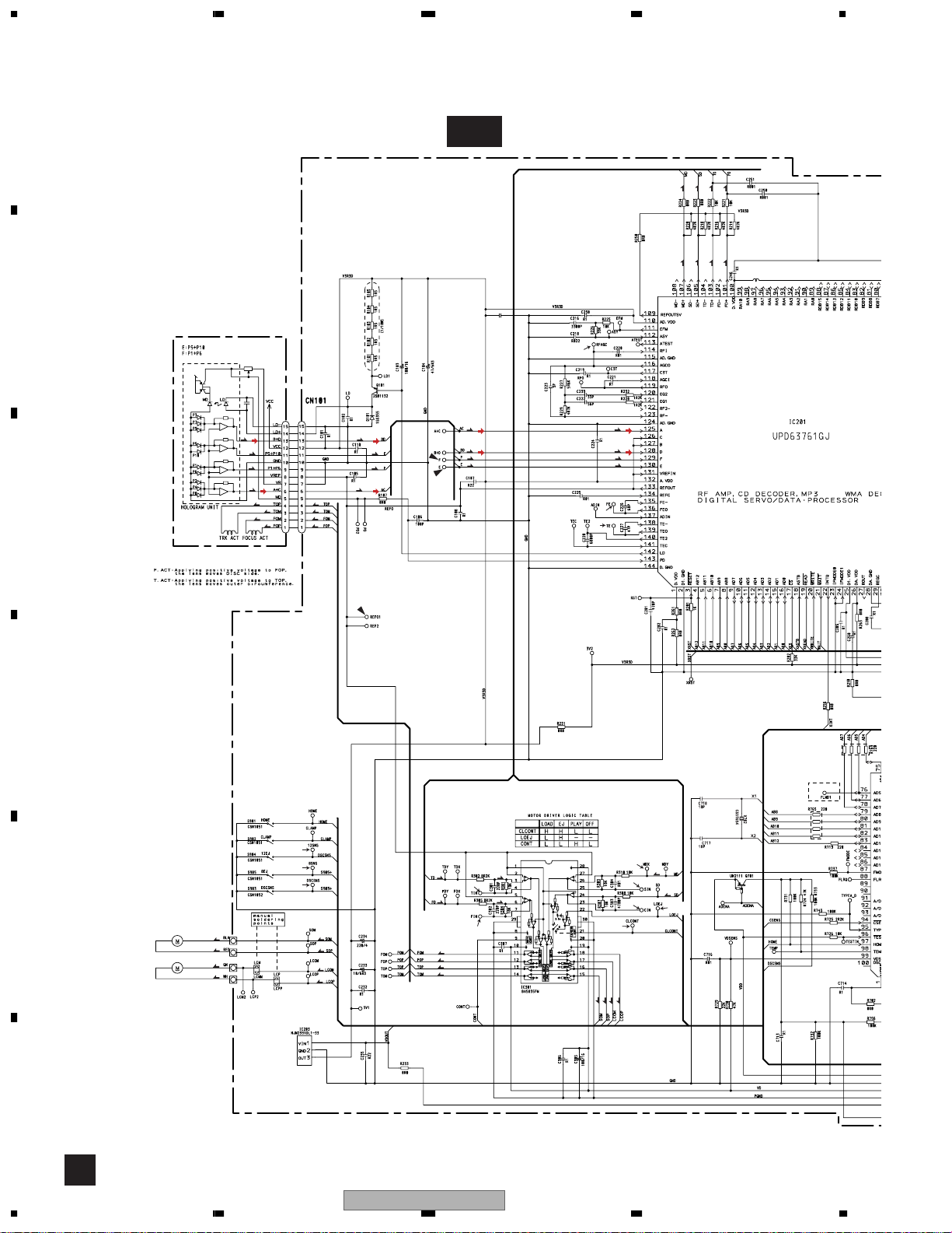
CN101
LD-
15
15
MD
5
5
FOP
FO+
1
1
TO+
TOP
4
4
LD+
14
14
S902
CLAMP
V3R3D
Q101
AC,BD
F,E
S904
12EJ
V3R3D
142
LD
143
PD
RF AMP, CD DECODER,
MP3 AND WMA DECODER
DIGITAL SERVO/DATA PROCESSOR
TD/FD
SD/MD
12
FOP
13
TOP
CD
DRIVER
16
SOP
15
SOM
18
LCOP
CONT
17
LCOM
IC 301
BA5835FM
S903
S905
DSCSNS
8EJ
3
IC 203
NJM2391DL1-33
3.3V REGULATOR
5
V1R5
IC 501
S-L2980A15MC-C6A
1.5V REGULATOR
F
LOEJ
S901
HOME
LPF
1
VDD
ROM_VDD
CF52
CF51
VDD_3.3
IC 201
UPD63761GJ
COMPUTER
53
22
LOEJ
9
47
CONT
4
CLAMP
32
12EJ
31
8EJ
30
DSCSNS
97
HOME
VD2
1,3
V3R3D
DI
SL
IC 5
←
5V 3.3V
IC 4
3.3V 2.5V
3.3V
TUN 3.3V
SYS+B
X702
1312
X1
X2
MICRO
IC 701
PE5423A
3VDD
SWITCH PCB
E
CK
NC
CE1
←
2.5V
34
XTAL
46
DOUT
26
FRxD
25
FTxD
46
CD3VON
49
VDCONT
3.3V REGULATOR
3
IC 703
S-812C33AUA-C2N
M951
AUTOMATIC
FLAP MOTOR
CLOSE
OPEN
EJECT
DO
RDS_CK
RDS_HSLK
RDS_DATA
RDS_LOCK
IC 2
2.5V
DET, FM MPX,
RDS DECODER
ASENB1
BUS+
BUS-
BUSL+
BUSL-
8
1
5
7
11
CDRX
B
CDTX
C
111213
2
DATA
39
A3V
CN902
MCK
CN901
DOUT
CN101
CN703
MCK2
1
1
RX
3
3
TX
4
4
CN701
DATA
14
12
12
3V 5V
IC 251
TC74VHC08FT
DRDY,RDY,DSPIN
BSCK,BDATA,BSRQ
BRXEN,BRST,CSENSOUT
VD
VD
3
VD
VDCONT
CD3VON
2
VDD
21
4
20
BU
VDCONT
19
5
MCKRQ
1
23
VDD
5
VD2
2
VDD
19
VD2
22
Q742
Q741
Q811
CN811
MOTOR1
MOTOR2
FCLSW1
FOPSW1
FEJSW1
3
14
IC 811
BA6288FS
M
6
5
4
3
2
1
SW
R
SDOUT2
SDOUT3
DSP
IC 271
AK7730VT
TC74VHC08FT
MECHA VD
45
Rch
24
Lch
23
F
SDOUT1
48
AINL+L
9
14
5V 3V
IC 252
RQ,DSPCK,
DSPOUT,DSPCS
D3V
Q743
Q812
6
11
D3V
5
TC7SH08FU
DAC5V
4
IC 272
1
Q744
MCKRQ
RDS_DATA
RDS_HSLK
RDS_CK
RDS_LOCK
Q101
IP-BUS DRIVER
6
IC 101
5
HA12240FP
3
DATA3
2
DATA2
1
DATA1
15
VCC
8
A3V
3
BU
11
FLPPW
66
FLPOPN
65
FLPCLS
69
fclssw
68
fopnsw
67
flpejsw
SL
ce@
CE1
DO
DI
CK
Q401
Q402
BU
1
2
8
DAC
FR
RR
IC 211
PCM1606EG
SWL
SWR
FL
RL
5
ADC INPUT
1
IC 231
NJM2100V
DSP MODE
PRO
DSPMOD
SYSTEM CONTROLLER
IC 601(2/2)
PD5913A
DSENS
94
11
13
8
9
10
12
97
71
72
56
55
57
47
25
18
46
82
30
29
81
DAC5V
45
MIC321
SL
pce@
PCE1
PDI
PDO
PCK
RDT
RDS57K
rck
rdslk
ASENBO
TX
RX
IPPW
VR321
SYSTEM CO
5
3
NJM455
SWL,SW
5
3
NJM455
5
3
NJM455
8
1
NJM455
DSPOUT,DS
STD
VDD
dsppw
MUTE
SYSPW
XOUT
XIN
OELPW
DPDT1
KYDT1
SWVDD1
RESET
ILMPW1
DIMMER
DISPPW
ILMPW2
DPDT2
KYDT2
SWVDD2
AS
IC 601(
PD591
FR,RR
IC 17
IC 17
FL,RL
IC 17
IC 20
LPF
44
87
23
13
15
BU
22
31
32
40
12
42
84
41
BU
43
35
36
79
1
16
1234
DEH-P9600MP/XN/EW
W
5678
A
MIC321
SL
97
SL
ce@
71
pce@
CE1
72
PCE1
DO
56
PDI
DI
55
PDO
CK
57
PCK
47
RDT
25
RDS57K
18
rck
46
rdslk
82
ASENBO
30
TX
29
RX
81
IPPW
11
FR
13
RR
8
L
9
R
10
FL
12
RL
DAC5V
1
DSP MODE
O
45
DSPMOD
NTROLLER
1(2/2)
13A
SENS
94
ASL
1
NJM4558MD
VR321
SYSTEM CONTROLLER
IC 601(1/2)
PD5913A
FR,RR ch
5
IC 172
3
NJM4558MD
SWL,SWR ch
5
IC 173
3
NJM4558MD
FL,RL ch
5
IC 171
3
NJM4558MD
8
IC 201
1
NJM4558MD
LPF
DSPOUT,DSPCK
STD
VDD
44
dsppw
87
MUTE
23
SYSPW
13
XOUT
X601
15
XIN
BU
22
OELPW
31
DPDT1
32
KYDT1
40
SWVDD1
12
1
RESET
42
ILMPW1
84
DIMMER
41
DISPPW
BU
43
ILMPW2
35
DPDT2
36
KYDT2
79
SWVDD2
IC 321
ASLIN
DALMON
bsens
asens
isens
TELIN
TUN L
BUSL+
BUSL-
7
1
7
1
7
1
5
OEL+B
Q842
RESET
IC 651
BD4835G
ILM+B
Q963
VDD2
PEE
FR
RR
SWL
SWR
SYS+B
FL
6
RL
Q833
Q962
3
90
24
20
73
74
83
10
Q841
2
SWVDD2
IC 322
NJM4558MD
BUZZER
E-VOL /
SOURCE SELECTOR
16
AM
8
Phone+
9
Phone-
IC 131
PML011A
38
In1R
36
In2R
35
In3L
34
In3R
39
In1L
37
In2L
44
Out1L
Q501
CDTX
C
5
TC74VHCT125AFT
2
ILM+B1
Q964
VDD
Q965
Q851
Q852
7
DSPPW
BU
CDRX
IC 871
11
BU
B
MPX-RDS
17
A
AUTOEQ
MUTE
8
Q651
Q752
Q321
SPKR3L
SPKR1L
SPKR2L
MUTE
9
VDD2
SWVDD1
Q835
AUTOEQ
AUTO
3
Q364
BL+B
EQ
VDD
VDD
BACKUP SENSE
Q931
ACC SENSE
SWL
25
29
FL
27
RL
Q861
Q862
Q834
A
Q751
12
FLIN
14
RLIN
22 4
Q301
SYSPW
CN871
OEL+B
5
DPDT1
4
KYDT1
6
SWVDD5V
1
ILM+B1
2
CN872
ILM+B
4
BL+B
33
RST1
5
DPDT2
10
KYDT2
11
SWVDD2
6
AEQMIC
77
AEQGND
2
DSENS
1
HIGH OUT
RL
9
IN3
SWL
11
IN5
7
FL
IN1
VDD REGULATOR
Q901
VDD
IC 571
PA2028A
Q902
Q951
OUT3
OUT5
OUT1
TELEPHONE MUTE
POWER AMP
PAL007A
STBYMUTE
SYS+B
KEYBOARD UNIT(OEL)
B
OEL+B
4
DPDT2
5
KYDT2
3
SWVDD5V2
8
ILM+B2
7
IC 301
D3V
A3V
1
B.REMOTE
NJM2391DL1-33
5
FLFL+
RL-
RL+
25
BU
TUNER 3V
IC 671
SYS+B REG
Q921
IC 1802
S-818A33AUC-BGN
CN1801
CONNECTOR PCB
F
CN1901
ILM+B
4
BL+B
RST
5
DPDT
10
KYDT
11
SWVDD5V
6
AEQMIC
AEQGND
2
DSENS
1
16
14
18
VDD2
Q941
ILL SENSE
3
5
23
21
DSP 3V REG
1
S-818A33AUC-BGN
Q692
3
Q922
Q923
RESET
SW5V
BU
1
IC 681
Q691
TUN3.3V
3.3V
5V REGULATOR
Q911
ACC
5
DAC 5V
1
3
IC 691
BA05FP
BU
12
OEL UNIT
27
DPDT
GRILLE µ-COM
28
KYDT
11
XOUT
X1801
13
XIN
KEY MATRIX
KEYBOARD UNIT(LCD)
C
18
Q1906
20
CN1902
CN351
Q352
Q353
Q351
CN981
BACK UP
TELMUTE
B.REM
DAC5V
IC 1805
PD5917A
RS2
32
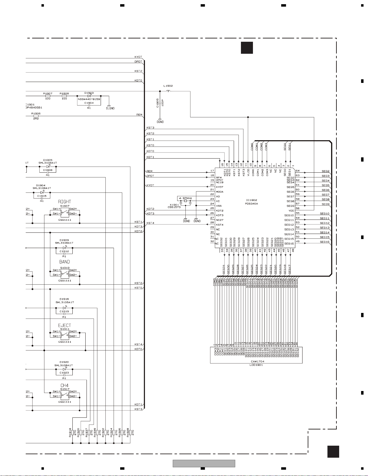
LCD1901
GRILLE µ-COM
DPDT
KYDT
RL
5
SWL
9
FL
1
1
ACC
5
ILL
3
8
GND
2
FL-
10
FL+
12
RL-
9
RL+
11
4
1
IC 1902
PD6340A
KEY MATRIX
RL
SWL
FL
FUSE
B.UP
10A
ACC
ILM
MUTE
GND
FLFL+
RLRL+
B.REM
BACK
UP
B.
ILL
REM
ACC
GND
IC 1806
PD8122A
MEMORY
IC 1807
PD6460A
7
IC 1808
TC7WH32FK
REMOTE CONTROL SENSOR
3
SW5V
TSOP4840SB1
17
REM
22
XO
23
XI
RR
-
FR
-
FL
-
RL
-
ROM
FLASH
ce
26
IC 1901
X1901
B
C
RR
+
FR
+
FL
+
RL
+
D
E
OPT IN
1
F
56
DEH-P9600MP/XN/EW
7
8
17
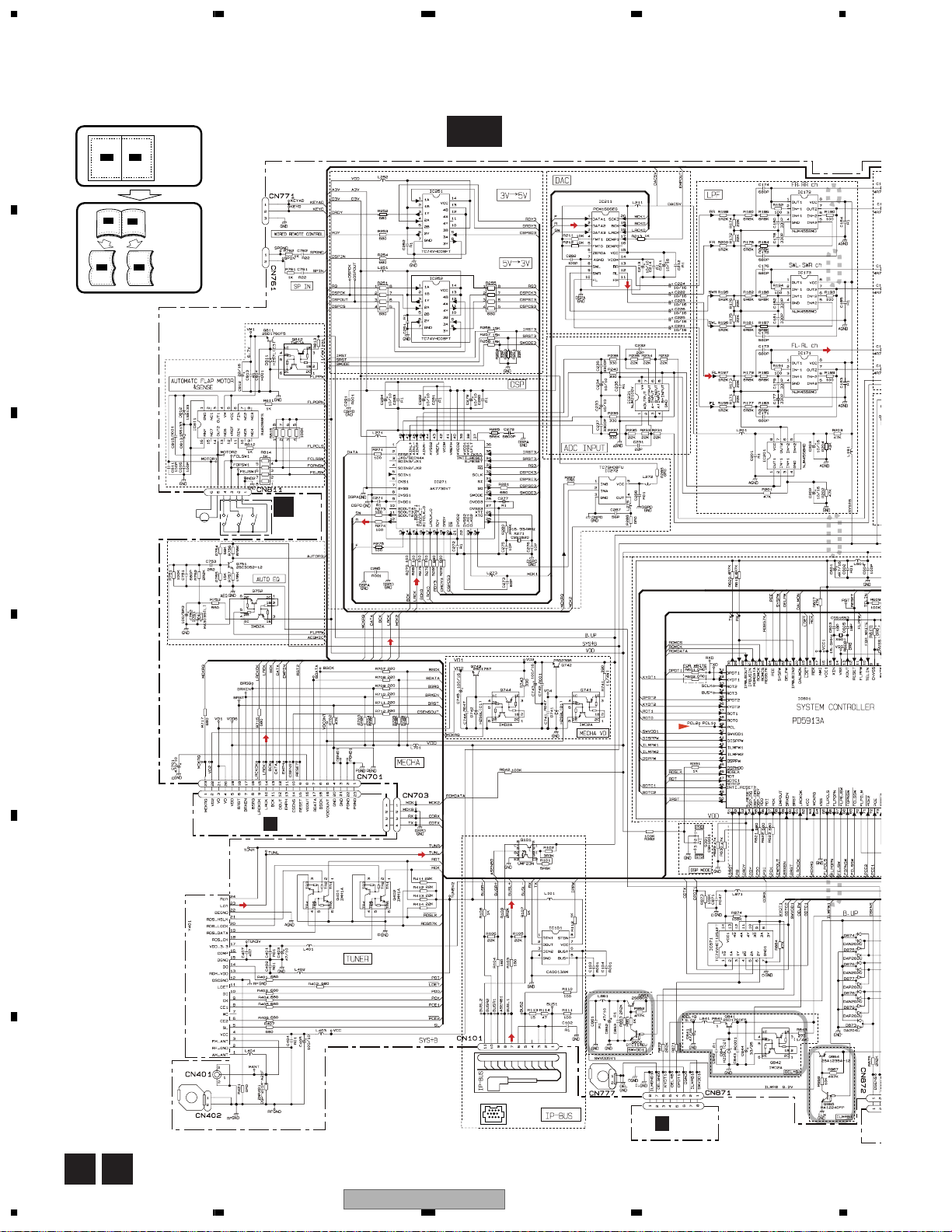
1234
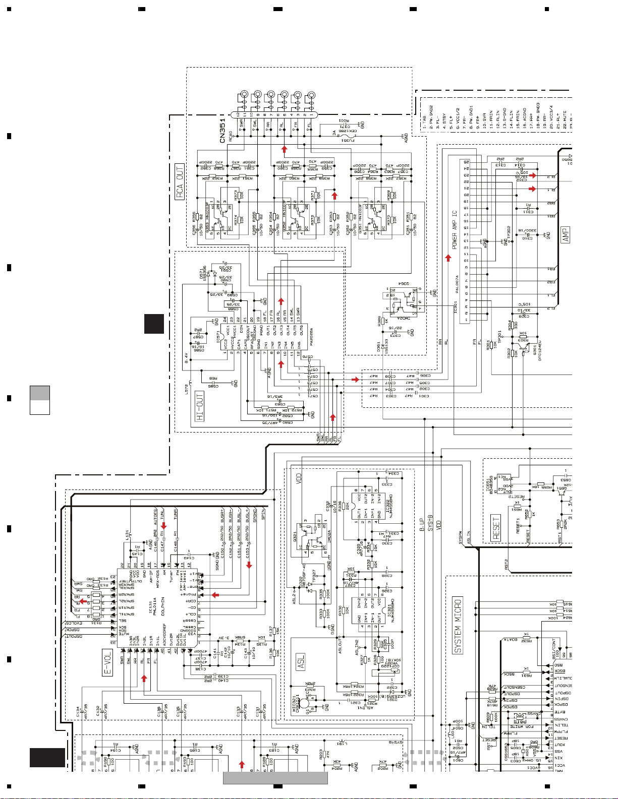
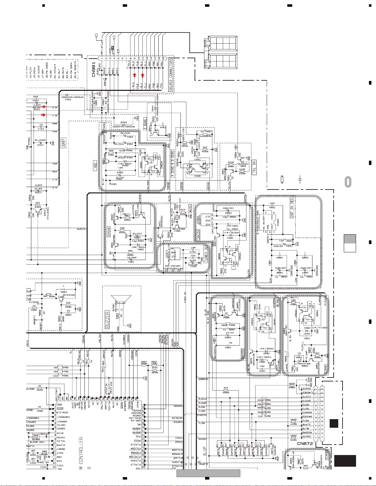
3.2 OVERALL CONNECTION DIAGRAM(GUIDE PAGE)
A
B
C
"ELECTRICAL PARTS LIST".
Large size
A-b
A-b
SCH diagram
Guide page
Detailed page
AUTOMATIC FLAP
M951
CXB8939
CSN1052
(CLOSE)
S951
CSN1051
(OPEN)
SWITCH
S953
CSN1058
(EJECT)
PCB
E
M
S952
A-a A-b
A-a
A-a
A-a
1
2
3
Note: When ordering service parts, be sure to refer to " EXPLODED VIEWS AND PARTS LIST" or
D
CN902
CN901
D
TUNER:-26.0dBs
(FM:30%, AM:30%)
4
E
FM/AM TUNER UNIT
IP-BUS:+2.2dBs
F
B
CN1801
18
A E
DEH-P9600MP/XN/EW
1234
5678
A
A-b
TUNER: -4.37dBs
1
IP-BUS:+7.66dBs
CD:+7.55dBs
2
TUNER:-27.3dBs
IP-BUS:+1.73dBs
3
The > mark found on some component parts indicates
the importance of the safety factor of the part.
Therefore, when replacing, be sure to use parts of
identical designation.
TUNER AMP UNIT
A
TUNER: +6.13dBs
IP-BUS:+18.16dBs
CD:+18.05dBs
B
SUB
WOOFER
R CH
SUB
WOOFER
L CH
REAR
R CH
REAR
L CH
FRONT
R CH
FRONT
L CH
>
C
BACKUP
>
CEK1136
10A
GND
ILL
B.REM
ACC
TEL
RL-
FLRL+
FL+
RR-
FRRR+
FR+
TUNER:+21.63dBs
IP-BUS:+33.66dBs
4
NOTE :
Symbol indicates a resistor.
No differentiation is made between chip resistors and
discrete resistors.
Symbol indicates a capacitor.
No differentiation is made between chip capacitors and
discrete capacitors.
Decimal points for resistor
and capacitor fixed values
F
are expressed as :
←
2.2 2R2
←
0.022 R022
: The power supply is shown with the marked box.
CD:+33.55dBs
RR
RR
+
-
BACK
FR
FR
UP
+
-
B.
FL
FL
ILL
REM
+
RL
RL
ACC
GND
+
-
D
E
F
A
56
DEH-P9600MP/XN/EW
7
8
19
1234
A
A-b
1
2
3
B
C
A-b
A-a
A-a
D
E
E
SWITCH
PCB
(EJECT)
CSN1058
S953
(OPEN)
CSN1051
S951
(CLOSE)
CSN1052
S952
M
M951
F
CXB8939
AUTOMATIC FLAP
A-a
20
E
DEH-P9600MP/XN/EW
1234
5678
A
4
A-b
B
CN1801
B
C
CN902
CN901
D
TUNER:-26.0dBs
(FM:30%, AM:30%)
FM/AM TUNER UNIT
IP-BUS:+2.2dBs
A-b
A-a
A-a
D
E
F
56
DEH-P9600MP/XN/EW
A-a
7
8
21
1234
A
REAR
L CH
REAR
R CH
FRONT
SUB
WOOFER
L CH
SUB
WOOFER
R CH
B
R CH
FRONT
L CH
>
TUNER AMP UNIT
the importance of the safety factor of the part.
Therefore, when replacing, be sure to use parts of
identical designation.
The > mark found on some component parts indicates
C
A-b
A-a
A
CD:+18.05dBs
IP-BUS:+18.16dBs
TUNER: +6.13dBs
D
TUNER:-27.3dBs
CD:+7.55dBs
IP-BUS:+7.66dBs
TUNER: -4.37dBs
IP-BUS:+1.73dBs
E
F
A-b
22
1
2
DEH-P9600MP/XN/EW
3
1234
P
5678
BACKU
ILL
GND
>
B.REM
10A
CEK1136
ACC
RL-
TEL
FR-
FL-
RL+
FR+
FL+
RR+
RR-
+
RR
-
RR
FR
FR
BACK
+
+
+
RL
FL
-
-
-
RL
FL
B.
REM
ACC
UP
ILL
GND
A
CD:+33.55dBs
IP-BUS:+33.66dBs
TUNER:+21.63dBs
B
←
←
Symbol indicates a resistor.
No differentiation is made between chip resistors and
discrete resistors.
Symbol indicates a capacitor.
No differentiation is made between chip capacitors and
discrete capacitors.
Decimal points for resistor
and capacitor fixed values
are expressed as :
2.2 2R2
0.022 R022
: The power supply is shown with the marked box.
NOTE :
C
A-b
A-a
D
E
4
DEH-P9600MP/XN/EW
56
F
F
A-b
7
8
23
1234
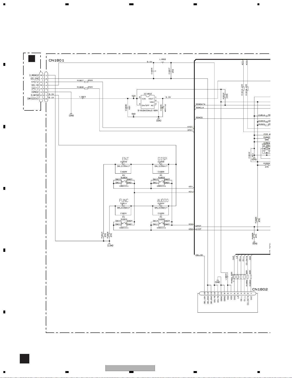
3.3 KEYBOARD UNIT(OEL)
A
A
CN871
B
C
D
E
OEL MODULE
F
B
24
1234
DEH-P9600MP/XN/EW

5678
A
KEYBOARD UNIT (OEL)
B
B
C
D
E
56
DEH-P9600MP/XN/EW
F
B
7
8
25
1234
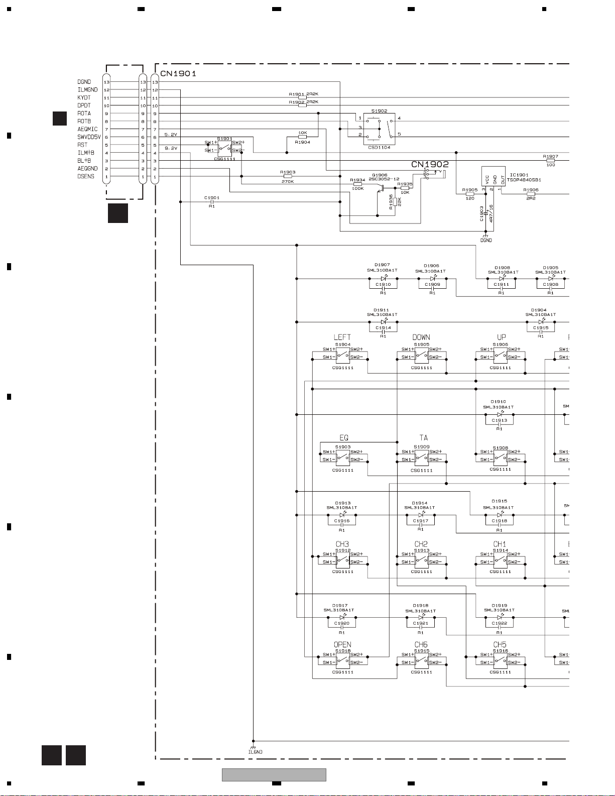
3.4 KEYBOARD UNIT(LCD)
A
A
SOURCE,VOLUME
CN872
B
F
CONNECTOR
PCB
C
RESET
REMOTE CONTROL
SENSOR
TEXT
D
E
F
26
C F
DEH-P9600MP/XN/EW
1234
5678
A
KEYBOARD UNIT (LCD)
C
TE CONTROL
OR
B
C
LCD CONTROLLER
D
56
DEH-P9600MP/XN/EW
E
F
C
7
8
27
1234
3.5 CD MECHANISM MODULE(GUIDE PAGE)
A
D-a
T
C
F
S
C
S
T
F
L209
B
PICKUP UNIT(P10)(SERVICE)
C217
R1
%
F
T
T
F
T
C
T
F
F
F
T
T
F
T
T
F
F
F
F
T
T
F
F
T
T
AND
#
@
D
Pull-down
4.00MHz
3
2
1
E
M1
CXB6007
SPINDLE MOTOR
M2
CXB8933
LOADING/CARRIAGE
MOTOR
S
S
C
C
S
S
C
C
T
F
T
9
F
0
F
F
T
T
CD DRIVER
$
S
7
C
8
4
5
S
S
C
C
3.3V REGULATOR
F
D
28
1234
DEH-P9600MP/XN/EW
5678
A
D-b
CD CORE UNIT(S10WMACODE2)
D
B
Pull-down
AND
!
MICRO COMPUTER
1.5V REGULATOR
SWITCHES:
CD CORE UNIT(S10WMACODE2)
S901 : HOME SWITCH.........ON-OFF
S902 : CLAMP SWITCH.......ON-OFF
S903 : DSCSNS SWITCH.....ON-OFF
S904 : 12EJ SWITCH............ON-OFF
S905 : 8EJ SWITCH..............ON-OFF
The underlined indicates the switch position.
SIGNAL LINE
F
FOCUS SERVO LINE
T
TRACKING SERVO LINE
C
CARRIAGE SERVO LINE
S
SPINDLE SERVO LINE
A
CN703
C
D
PE5423A
3.3V REGULATOR
C722
1
6
C910
DEH-P9600MP/XN/EW
56
C906 R22
E
^
LRCKOK
LRCK
BCK
A
DOUT
CN701
EMPH
470P
* &
2R2
F
D
7
8
29
 Loading...