

PIONEER DEHP790BT, DEH P7900BT, DEHP8950BT Service Manual
CD RECEIVER
ORDER NO.
CRT3903
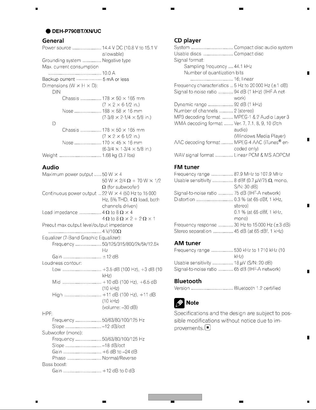
DEH-P790BT/XN/UC
DEH-P790BT
DEH-P7900BT
DEH-P8950BT
This service manual should be used together with the following manual(s):
Model No. Order No. Mech.Module Remarks
CX-3195 CRT3815 S10.5COMP2 CD Mech. Module : Circuit Descriptions, Mech. Descriptions, Disassembly
/XN/UC
/XN/ES
/XN/UC
For details, refer to "Important Check Points for Good Servicing".
PIONEER CORPORATION 4-1, Meguro 1-chome, Meguro-ku, Tokyo 153-8654, Japan
PIONEER ELECTRONICS (USA) INC. P.O. Box 1760, Long Beach, CA 90801-1760, U.S.A.
PIONEER EUROPE NV Haven 1087, Keetberglaan 1, 9120 Melsele, Belgium
PIONEER ELECTRONICS ASIACENTRE PTE. LTD. 253 Alexandra Road, #04-01, Singapore 159936
PIONEER CORPORATION 2007
K-ZZA. MAR. 2007 Printed in Japan
1234
SAFETY INFORMATION
CAUTION
A
This service manual is intended for qualified service technicians; it is not meant for the casual do-it-yourselfer.
Qualified technicians have the necessary test equipment and tools, and have been trained to properly and safely repair
complex products such as those covered by this manual.
Improperly performed repairs can adversely affect the safety and reliability of the product and may void the warranty.
If you are not qualified to perform the repair of this product properly and safely, you should not risk trying to do so
and refer the repair to a qualified service technician.
WARNING
This product contains lead in solder and certain electrical parts contain chemicals which are known to the state of
California to cause cancer, birth defects or other reproductive harm.
B
Health & Safety Code Section 25249.6 - Proposition 65
- Safety Precautions for those who Service this Unit.
When checking or adjusting the emitting power of the laser diode exercise caution in order to get safe, reliable
results.
Caution:
1. During repair or tests, minimum distance of 13 cm from the focus lens must be kept.
2. During repair or tests, do not view laser beam for 10 seconds or longer.
C
Danger of explosion if battery is incorrectly replaced.
Replaced only with the same or equivalent type recommended by the manufacture.
Discord used batteries according to the manufacture's instructions.
- Service Precaution
1. You should conform to the regulations governing
D
the product (safety, radio and noise, and other
regulations), and should keep the safety during
servicing by following the safety instructions
described in this manual.
2. Before disassembling the unit, be sure to turn off
the power. Unplugging and plugging the connectors
during power-on mode may damage the ICs inside
the unit.
3. To protect the pickup unit from electrostatic discharge
during servicing, take an appropriate treatment
(shorting-solder) by referring to "the DISASSEMBLY".
4. After replacing the pickup unit, be sure to check the
E
grating.
5. Be careful in handling ICs. Some ICs such as MOS
type are so fragile that they can be damaged by
electrostatic induction.
6. When diagnosing a product, take care of its heated
portion.
Holder (CND3133)
Bluetooth Unit
CAUTION
F
2
1234
DEH-P790BT/XN/UC
5 678
[Important Check Points for Good Servicing]
In this manual, procedures that must be performed during repairs are marked with the below symbol.
Please be sure to confirm and follow these procedures.
1. Product safety
Please conform to product regulations (such as safety and radiation regulations), and maintain a safe servicing environment by
following the safety instructions described in this manual.
1 Use specified parts for repair.
Use genuine parts. Be sure to use important parts for safety.
2 Do not perform modifications without proper instructions.
Please follow the specified safety methods when modification(addition/change of parts) is required due to interferences such as
radio/TV interference and foreign noise.
3 Make sure the soldering of repaired locations is properly performed.
When you solder while repairing, please be sure that there are no cold solder and other debris.
Soldering should be finished with the proper quantity. (Refer to the example)
4 Make sure the screws are tightly fastened.
Please be sure that all screws are fastened, and that there are no loose screws.
5 Make sure each connectors are correctly inserted.
Please be sure that all connectors are inserted, and that there are no imperfect insertion.
6 Make sure the wiring cables are set to their original state.
Please replace the wiring and cables to the original state after repairs.
In addition, be sure that there are no pinched wires, etc.
7 Make sure screws and soldering scraps do not remain inside the product.
Please check that neither solder debris nor screws remain inside the product.
8 There should be no semi-broken wires, scratches, melting, etc. on the coating of the power cord.
Damaged power cords may lead to fire accidents, so please be sure that there are no damages.
If you find a damaged power cord, please exchange it with a suitable one.
9 There should be no spark traces or similar marks on the power plug.
When spark traces or similar marks are found on the power supply plug, please check the connection and advise on secure
connections and suitable usage. Please exchange the power cord if necessary.
a Safe environment should be secured during servicing.
When you perform repairs, please pay attention to static electricity, furniture, household articles, etc. in order to prevent injuries.
Please pay attention to your surroundings and repair safely.
A
B
C
D
2. Adjustments
To keep the original performance of the products, optimum adjustments and confirmation of characteristics within specification.
Adjustments should be performed in accordance with the procedures/instructions described in this manual.
3. Lubricants, Glues, and Replacement parts
Use grease and adhesives that are equal to the specified substance.
Make sure the proper amount is applied.
4. Cleaning
For parts that require cleaning, such as optical pickups, tape deck heads, lenses and mirrors used in projection monitors, proper
cleaning should be performed to restore their performances.
5. Shipping mode and Shipping screws
To protect products from damages or failures during transit, the shipping mode should be set or the shipping screws should be
installed before shipment. Please be sure to follow this method especially if it is specified in this manual.
56
DEH-P790BT/XN/UC
E
F
7
8
3

1234
CONTENTS
SAFETY INFORMATION..................................................................................................................................... 2
1. SPECIFICATIONS............................................................................................................................................ 5
2. EXPLODED VIEWS AND PARTS LIST............................................................................................................ 8
A
B
C
D
2.1 PACKING(DEH-P790BT/XN/UC)............................................................................................................... 8
2.2 PACKING(DEH-P7900/BT/XN/UC, DEH-P8950BT/XN/ES) .................................................................... 10
2.3 EXTERIOR(1) .......................................................................................................................................... 12
2.4 EXTERIOR(2) .......................................................................................................................................... 14
2.5 CD MECHANISM MODULE..................................................................................................................... 16
3. BLOCK DIAGRAM AND SCHEMATIC DIAGRAM ......................................................................................... 18
3.1 BLOCK DIAGRAM ................................................................................................................................... 18
3.2 OVERALL CONNECTION DIAGRAM(GUIDE PAGE) ............................................................................. 22
3.3 KEYBOARD UNIT.................................................................................................................................... 28
3.4 CD MECHANISM MODULE(GUIDE PAGE) ............................................................................................ 30
3.5 BLUETOOTH UNIT, ANTENNA UNIT...................................................................................................... 38
4. PCB CONNECTION DIAGRAM ..................................................................................................................... 40
4.1 TUNER AMP UNIT................................................................................................................................... 40
4.2 KEYBOARD UNIT.................................................................................................................................... 44
4.3 CD CORE UNIT(S10.5COMP2)............................................................................................................... 46
4.4 BLUETOOTH UNIT.................................................................................................................................. 48
4.5 ANTENNA UNIT ...................................................................................................................................... 50
4.6 SWITCH UNIT ......................................................................................................................................... 51
5. ELECTRICAL PARTS LIST ............................................................................................................................ 52
6. ADJUSTMENT ............................................................................................................................................... 61
6.1 CD ADJUSTMENT................................................................................................................................... 61
6.2 CHECKING THE GRATING AFTER CHANGING THE PICKUP UNIT.................................................... 63
6.3 ERROR MODE ........................................................................................................................................ 65
6.4 TEST MODE (iPod) ................................................................................................................................. 66
6.5 TEST MODE (USB) ................................................................................................................................. 67
6.6 SYSTEM MICROCOMPUTER TEST PROGRAM................................................................................... 68
6.7 TEST MODE (Bluetooth) ......................................................................................................................... 69
7. GENERAL INFORMATION............................................................................................................................. 74
7.1 DIAGNOSIS ............................................................................................................................................. 74
7.1.1 DISASSEMBLY..................................................................................................................................... 74
7.1.2 CONNECTOR FUNCTION DESCRIPTION.......................................................................................... 79
7.2 IC ............................................................................................................................................................. 80
7.3 OPERATIONAL FLOW CHART............................................................................................................... 92
8. OPERATIONS ................................................................................................................................................ 93
E
F
4
1234
DEH-P790BT/XN/UC
5 678
1. SPECIFICATIONS
A
B
C
D
E
56
DEH-P790BT/XN/UC
F
7
8
5
1234
A
B
C
D
E
F
6
1234
DEH-P790BT/XN/UC
5 678
A
B
C
D
E
56
DEH-P790BT/XN/UC
F
7
8
7
1234
N
2. EXPLODED VIEWS AND PARTS LIST
OTES : Parts marked by " * " are generally unavailable because they are not in our Master Spare Parts List.
The > mark found on some component parts indicates the importance of the safety factor of the part.
A
Therefore, when replacing, be sure to use parts of identical designation.
Screw adjacent to mark on the product are used for disassembly.
For the applying amount of lubricants or glue, follow the instructions in this manual.
(In the case of no amount instructions,apply as you think it appropriate.)
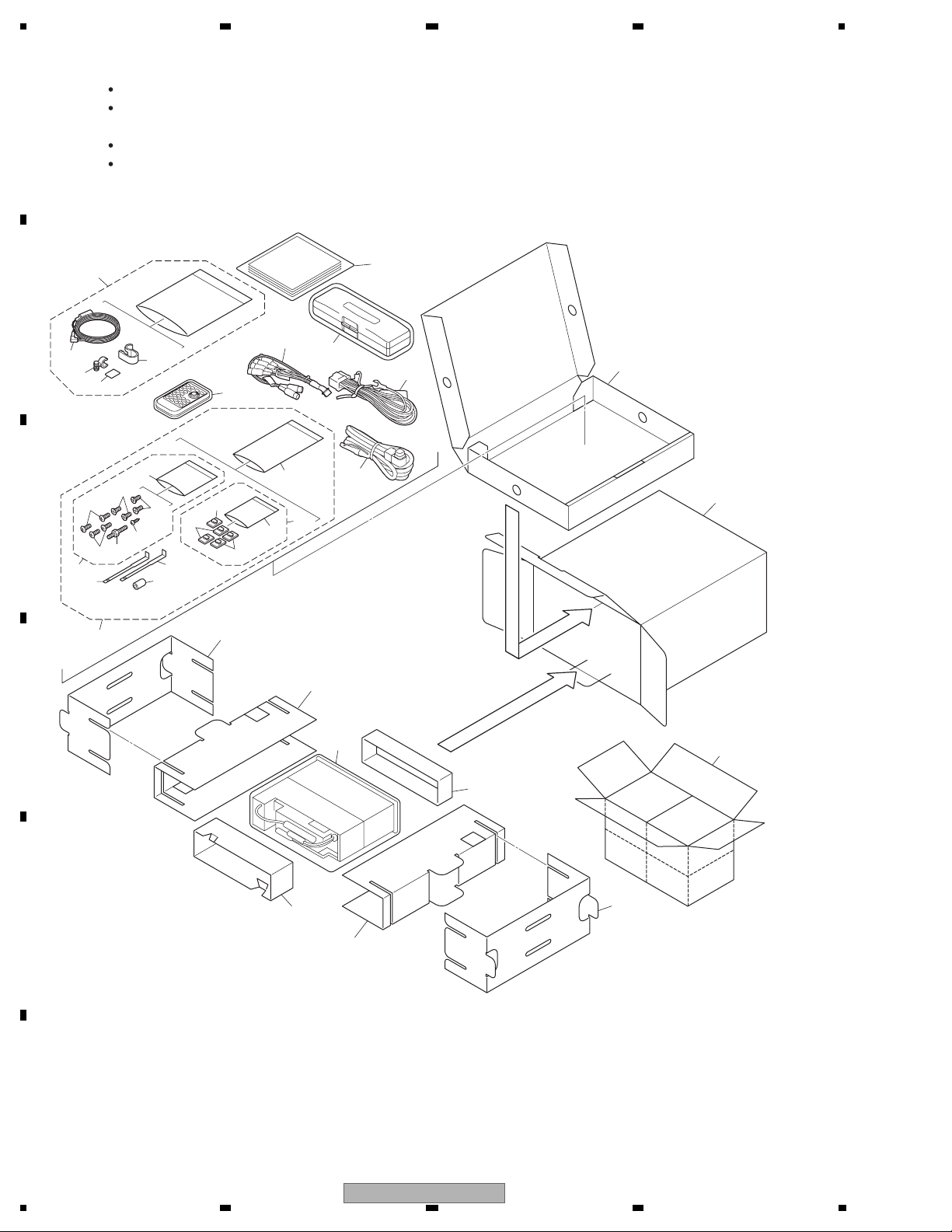
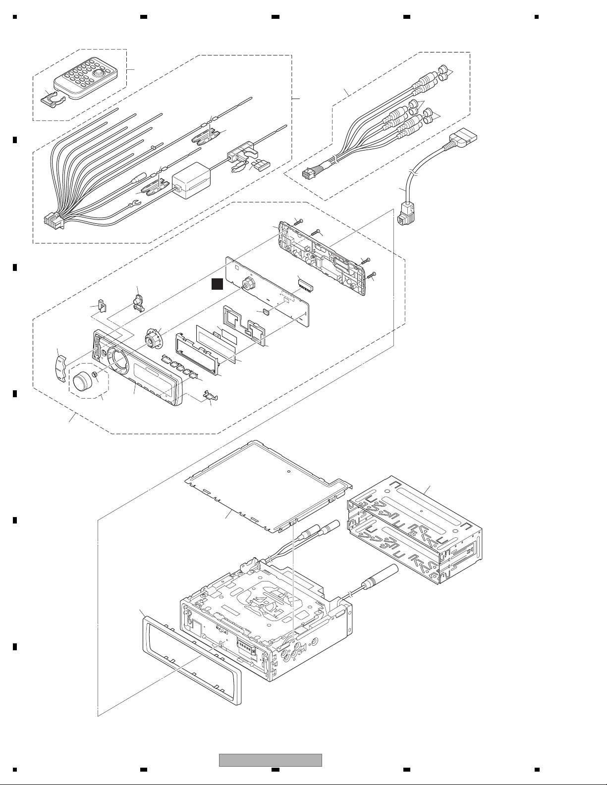
2.1 PACKING(DEH-P790BT/XN/UC)
""
32
30
2
16
17
23
B
1
27
25
26
C
12
12
7
14
3
10
8
11
24
28
9
10
14
15
5
5
20
6
5
29
13
4
19
D
31
22
E
21
19
20
18
DEH-P790BT/XN/UC packing
F
8
1234
DEH-P790BT/XN/UC

5 678
PACKING(DEH-P790BT/XN/UC) SECTION PARTS LIST
Mark No. Description Part No.
1 Cord Assy CDE8284
2 Cord Assy CDP1009
* 3 Accessory Assy CEA7537
4 Cord Clamper Assy CEA4636
* 5 Clamper CNV8262
* 6 Polyethylene Bag E36-615
7 Screw Assy CEA5322
8 Screw CBA1650
* 9 Polyethylene Bag CEG-127
10 Screw CRZ50P090FTC
A
11 Screw JPZ20P060FTB
12 Screw TRZ50P080FTC
* 13 Polyethylene Bag CEG1160
14 Handle CND3707
15 Bush CNV3930
16 Sub Unit Box CHG5195
17 Unit Box CHG6114
18 Contain Box CHL6114
19 Protector CHP2797
20 Protector CHP2798
21 Protector CHP2812
22 Protector CHP3333
23 Microphone Assy CPM1064
24 Clip Holder CZN5471
25 Microphone Holder CZN5472
26 Cushion CZN5473
* 27 Microphone CZX5059
28 Remote Control Unit CXC7555
29 Case Assy XXA7417
30-1 Owner's Manual CRD4204
(English, French)
B
C
D
30-2 Installation Manual CRD4209
(English, French)
30-3 Caution Card CRP1310
* 30-4 Warranty Card CRY1070
* 30-5 Caution Card XRP7002
30-6 Polyethylene Bag CEG1116
* 30-7 Caution Card CRP1359
31 Polyethylene Bag CEG1368
32 Cord Assy XDP7005
56
DEH-P790BT/XN/UC
E
F
7
8
9
1234
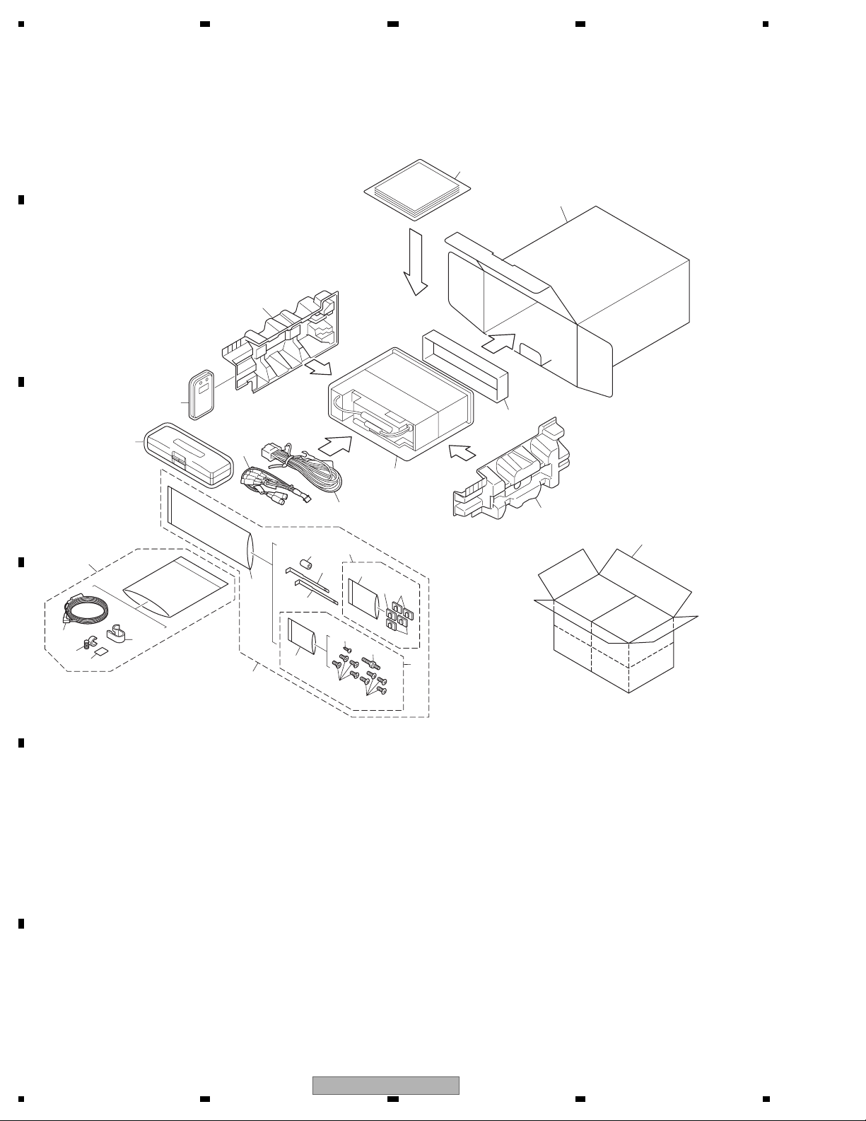
2.2 PACKING(DEH-P7900/BT/XN/UC, DEH-P8950BT/XN/ES)
A
27
DEH-P7900 & 8950 packing
3
B
6
26
29
7
C
21
1
28
18
20
19
2
9
11
10
10
5
4
19
15
16
13
10
12
24
D
23
25
22
14
8
17
E
F
10
1234
DEH-P790BT/XN/UC
5 678
(1) PACKING(DEH-P7900BT/XN/UC, DEH-P8950BT/XN/ES) SECTION PARTS LIST
No. Description Part No.
Mark No. Description Part No.
1 Cord Assy CDE8284
2 Cord Assy CDP1009
3 Unit box See Contrast table(2)
4 Contain box See Contrast table(2)
5 Protector L CHP3373
6 Protector R CHP3374
7 Case Assy XXA7417
* 8 Accessory Assy See Contrast table(2)
9 Cord Clamper Assy CEA4636
* 10 Clamper CNV8262
* 11 Polyethylene Bag E36-615
12 Screw Assy See Contrast table(2)
13 Screw CBA1650
* 14 Polyethylene Bag CEG-127
15 Screw CRZ50P090FTC
16 Screw See Contrast table(2)
17 Screw TRZ50P080FTC
* 18 Polyethylene Bag CEG1160
Mark
19 Handle CND3707
20 Bush CNV3930
21 Microphone Assy CPM1064
22 Clip Holder CZN5471
23 Microphone Holder CZN5472
* 24 Microphone CZX5059
25 Cushion CZN5473
26 Remote Control Unit CXC7555
27-1 Owner's manual See Contrast table(2)
27-2 Owner's Manual See Contrast table(2)
27-3 Installation Manual See Contrast table(2)
27-4 Caution Card CRP1310
* 27-5 Warranty Card See Contrast table(2)
* 27-6 Caution Card XRP7002
27-7 Polyethylene Bag CEG1116
* 27-8 Caution Card See Contrast table(2)
28 Polyethylene Bag See Contrast table(2)
29 Protector CHP3375
A
B
(2) CONTRAST TABLE
DEH-P7900BT/XN/UC and DEH-P8950BT/XN/ES are constructed the same except for the following:
Mark No. Description DEH-P7900BT/XN/UC DEH-P8950BT/XN/ES
3 Unit box CHG6111 CHG6110
4 Contain box CHL6111 CHL6110
* 8 Accessory Assy CEA7537 CEA7536
12 Screw Assy CEA5322 CEA3849
16 Screw JPZ20P060FTB Not used
27-1 Owner's Manual CRD4205 CRD4206
27-2 Owner's Manual Not used CRD4207
27-3 Installation Manual CRD4210 CRD4211
* 27-5 Warranty Card CRY1246 Not used
* 27-8 Caution Card CRP1358 Not used
28 Polyethylene Bag CEG1173 CEG-162
Owner's Manual,Installation Manual
Part No. Language
CRD4205 English, French
CRD4206 English, Spanish, Portuguese(B)
CRD4207 Arabic, Traditional Chinese
CRD4210 English, French
CRD4211 English, Spanish, Portuguese(B), Arabic, Traditional Chinese
C
D
E
56
DEH-P790BT/XN/UC
F
7
8
11
1234
2.3 EXTERIOR(1)
A
28
27
1
3
30
2
2
2
5
30
4
31
B
5
10
13
10
10
16
26
14
C
21
25
18
BB
10
15
19
20
17
23
24
22
9
11
12
DEH-P790BT/XN/UC 1/2
D
7
6
E
8
F
12
DEH-P790BT/XN/UC
1234
5 678
(1) EXTERIOR(1) SECTION PARTS LIST
No. Description Part No.
Mark No. Description Part No.
1 Cord Assy CDE8284
2 Cap CNV6727
3 Cord Assy CDP1009
> 4 Fuse(10 A) CEK1136
Mark
17 Holder CND3781
18 Double Sided Tape CNM8673
19 Holder CNV9435
20 OEL Unit MXS8260
5 Cap CNS1472
21 Holder CNV9676
6 Case CNB3447
7 Holder CND3598
8 Panel See Contrast table(2)
9 Detach Grille Assy See Contrast table(2)
22 Knob Unit CXC7271
23 Spring XBL7005
24 Sub Grille Assy See Contrast table(2)
25 Button Unit(SRC/BAND) CXC7558
10 Screw BPZ20P080FTB
26 Button Unit(PHONE) CXC7559
11 Button(LIST/ATT/EQ/DISP/CLOCK)CAI1154
12 Button(EJECT) CAI1155
13 Cover CNS8491
14 Lighting Conductor CNV9509
27 Remote Control Unit CXC7555
28 Cover CZN5357
29 •••••
30 Resistor RS1/2PMF102J
15 Connector(CN1961) CKS5545
31 Cord Assy See Contrast table(2)
16 Connector(CN1801) CKS5662
(2) CONTRAST TABLE
DEH-P790BT/XN/UC, DEH-P7900BT/XN/UC and DEH-P8950BT/XN/ES are constructed the same except for the
following:
Mark No. Description DEH-P790BT/XN/UC DEH-P7900BT/XN/UC DEH-P8950BT/XN/ES
8 Panel CNS8914 CNS8915 CNS8915
9 Detach Grille Assy CXC7496 CXC7495 CXC7497
24 Sub Grille Assy CXC7501 CXC7500 CXC7502
31 Cord Assy XDP7005 Not Used Not Used
A
B
C
D
E
F
56
DEH-P790BT/XN/UC
7
8
13
1234
59
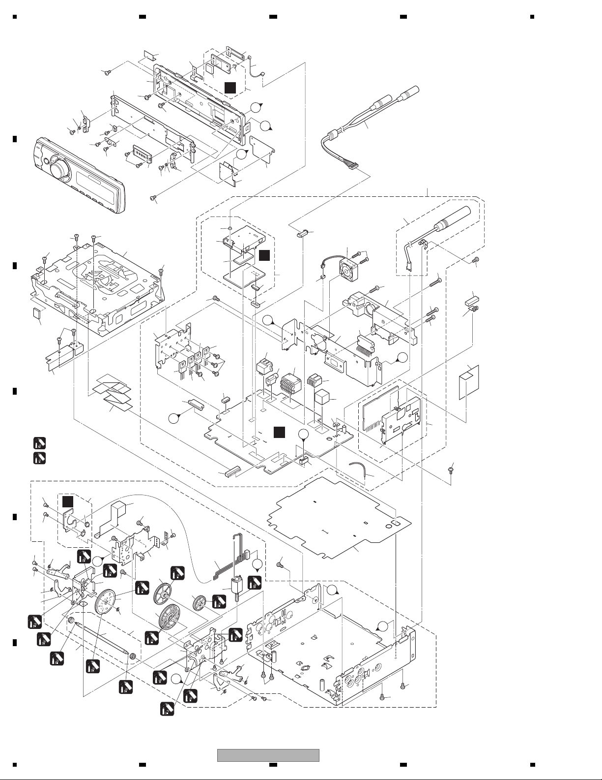
2.4 EXTERIOR(2)
47
2
49
51
45
45
A
46
45
52
53
50
56
64
48
46
60
56
47
58
49
63
EE
62
57
61
A
C
B
54
55
4
12
B
1
1
C
1
8
1
90
7
5
: GEM1024
D
: GEM1069
(2)
67
73
FF
75
67
74
3
89
78
E
3
89
86
66
A
85
66
72
89
88
87
82
66
31
71
81
70
2
1
93
B
25
93
13
92
16
39
38
23
40
93
43
16
DD
37
27
36
28
D
24
AA
20
26
42
17
44
41
32
21
29
30
F
22
35
19
14
33
18
15
1
10
15
6
14
E
9
34
91
67
80
68
(2)
69
84
1
F
11
D
E
65
F
14
1234
83
C
79
79
77
89
76
89
3
DEH-P790BT/XN/UC
66
66
3
66

5 678
(1) EXTERIOR(2) SECTION PARTS LIST
Mark No. Description Part No.
1 Screw BSZ26P060FTC
2 Screw(M2.6 x 4) CBA1828
3 Screw(M2 x 2.5) CBA1924
4 Cord Assy CDE8051
5 Cable CDE8388
6 Earth Plate CND2171
7 Holder CND3606
8 Insulator CNM7682
9 Insulator CNM8790
10 Cushion CNM9126
11 Insulator CNM9936
12 Tuner Amp Unit See Contrast table(2)
13 Screw BMZ26P040FTC
14 Screw BMZ26P100FTC
15 Screw BMZ26P180FTC
16 Screw BSZ26P060FTC
17 Screw(M2.6 x 14) CBA1632
18 Antenna Cable(CN401) CDH1336
19 Clamper CEF1050
20 Plug(CN981) CKM1278
21 Connector(CN301) CKM1389
22 Plug(CN881) CKS-786
23 Connector(CN701) CKS3829
24 Connector(CN151) See Contrast table(2)
25 Connector(CN801) CKS4811
26 Connector(CN181) CKS4980
27 Connector(CN101) CKS5271
28 Connector(CN521) CKS5321
29 Connector(CN561) CKS5683
30 Holder(CN983) CNC5399
31 Holder CND3133
32 Holder See Contrast table(2)
33 Heat Sink CNR1904
34 FM/AM Tuner Unit CWE1952
35 Holder CND1054
36 Bluetooth Unit CWN2339
37 Connector(CN76) CKS5320
38 Connector(CN1) CKS5749
39 Shield CND3134
40 Sheet CNM9598
41 IC(IC351) PAL007C
42 Fan Motor CXM1288
43 7P FFC Connector (CN522) VKN1299
44 ZH Connector 2P (CN891) VKN1928
45 Screw(M2 x 2) CBA1871
46 Screw(M2 x 2) CBA1935
47 Spring CBH2530
Mark
No. Description Part No.
48 Connector CKS5273
49 Arm CNV6962
50 Guide CNV6967
51 Guide CNV8048
52 Case Unit CXC5695
53 Screw(M2 x 3.5) XBA7002
54 Holder XNC7019
55 Flexible PCB XNP7026
56 Screw(M2 x 3.5) CBA2030
57 Cord Assy CDE8474
58 Earth Plate CND3138
59 Holder CND3139
60 Insulator CNN1499
61 Antenna Unit CWN2634
62 Connector(ANT1102) CKS5749
63 BT Antenna(ANT1101) CWX3132
64 Panel Unit See Contrast table(2)
65 Drive Unit CXC8074
66 Screw BMZ26P040FTC
67 Screw(M2 x 2) CBA1871
68 Cord CDE7392
69 Gear CNV7752
70 Gear CNV7753
71 Gear CNV7754
72 Gear CNV7755
73 Switch Unit CWS1389
74 Switch CSN1051
75 Spring Switch CSN1052
76 Arm Unit CXC2199
77 Arm Unit CXC6623
78 Arm Unit CXC6624
79 Screw JFZ20P020FTC
80 Spring XBL7003
81 Holder XNC7017
82 Insulator XNM7119
83 Holder Unit XXA7399
84 Motor Unit XXA7400
85 Holder Unit XXA7401
86 Arm Unit XXA7403
87 Gear Unit XXA7424
88 Shaft XLA7001
89 Washer YE15FTC
90 CD Mechanism Module(S10.5) CXK5763
91 Screw ISS26P055FTC
92 IC(IC911) NJM2388F84
93 Transistor(Q453,Q751,Q901) 2SD2396
A
B
C
D
E
(2) CONTRAST TABLE
DEH-P790BT/XN/UC, DEH-P7900BT/XN/UC and DEH-P8950BT/XN/ES are constructed the same except for the
following:
Mark No. Description DEH-P790BT/XN/UC DEH-P7900BT/XN/UC DEH-P8950BT/XN/ES
12 Tuner Amp Unit CWN2343 CWN2343 CWN2344
24 Connector(CN151) CKS4124 CKS4124 Not used
32 Holder CND3834 CND3834 CND3835
64 Panel Unit CXC6608 CXC5696 CXC5696
56
DEH-P790BT/XN/UC
7
8
F
15
1234
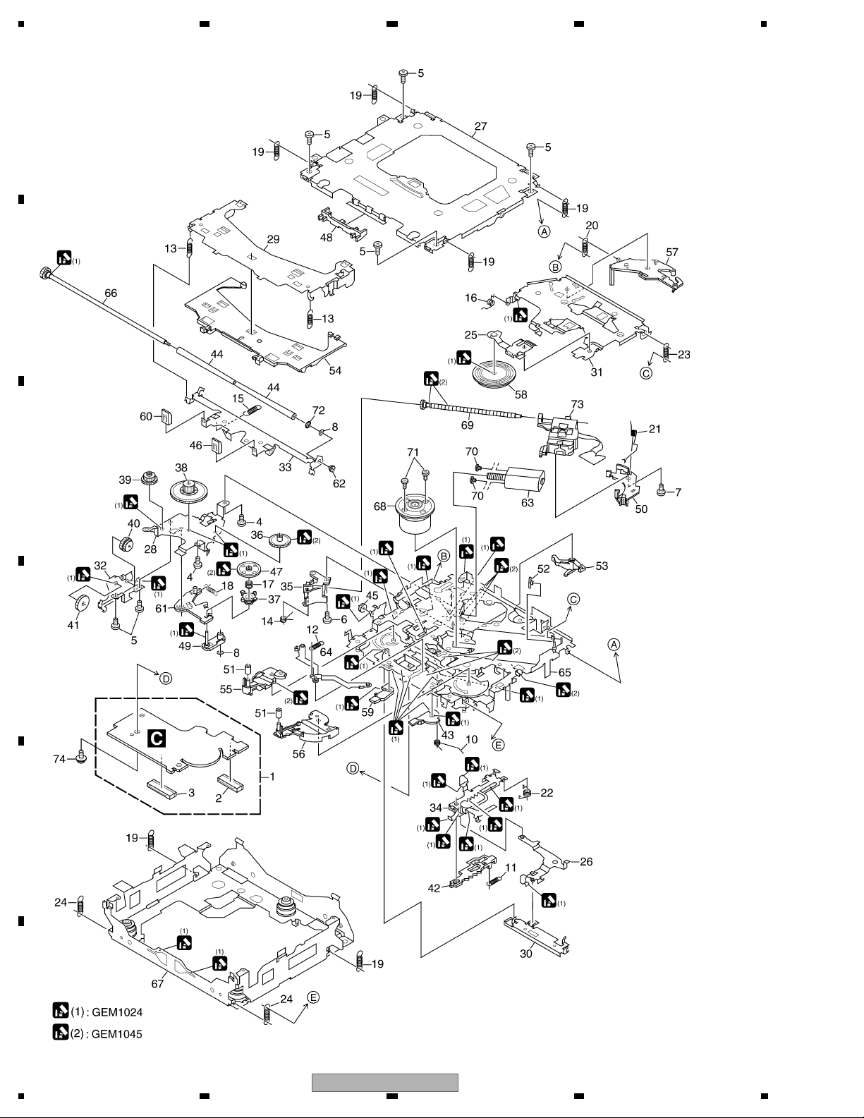
2.5 CD MECHANISM MODULE
A
B
C
D
E
F
16
1234
DEH-P790BT/XN/UC

5 678
CD MECHANISM MODULE SECTION PARTS LIST
Mark No. Description Part No.
1 CD Core Unit(S10.5COMP2) CWX3514
2 Connector(CN101) CKS4182
3 Connector(CN701) CKS4808
4 Screw BMZ20P025FTC
5 Screw BSZ20P040FTC
6 Screw(M2 x 3) CBA1511
7 Screw(M2 x 4) CBA1835
8 Washer CBF1038
9 •••••
10 Spring CBH2609
11 Spring CBH2612
12 Spring CBH2614
13 Spring CBH2616
14 Spring CBH2617
15 Spring CBH2620
16 Spring CBH2855
17 Spring CBH2937
18 Spring CBH2735
19 Spring CBH2854
20 Spring CBH2642
21 Spring CBH2856
22 Spring CBH2857
23 Spring CBH2860
24 Spring CBH2861
25 Spring CBL1686
26 Arm CND1909
27 Frame CND2582
28 Bracket CND2583
29 Arm CND2584
30 Lever CND2585
No. Description Part No.
Mark
50 Rack CNV8342
51 Roller CNV8343
52 Holder CNV8344
53 Arm CNV8345
54 Guide CNV8347
55 Arm CNV8348
56 Arm CNV8349
57 Arm CNV8350
58 Clamper CNV8365
59 Arm CNV8386
60 Guide CNV8396
61 Arm CNV8413
62 Collar CNV8938
63 Motor Unit(M2) CXC4026
64 Arm Unit CXC4027
65 Chassis Unit CXC4028
66 Gear Unit CXC4029
67 Frame Unit CXC4031
68 Motor Unit(M1) CXC7134
69 Screw Unit CXC6359
70 Screw JFZ20P020FTC
71 Screw JGZ17P022FTC
72 Washer YE20FTC
73 Pickup Unit(P10.5)(Service) CXX1942
74 Screw IMS26P030FTC
A
B
C
D
31 Arm CND2586
32 Bracket CND2587
33 Arm CND2588
34 Lever CND2589
35 Holder CNV7201
36 Gear CNV7207
37 Gear CNV7208
38 Gear CNV7209
39 Gear CNV7210
40 Gear CNV7211
41 Gear CNV7212
42 Rack CNV7214
43 Arm CNV7216
44 Roller CNV7218
45 Gear CNV7219
46 Guide CNV7361
47 Gear CNV7595
48 Guide CNV7799
49 Arm CNV7805
56
DEH-P790BT/XN/UC
E
F
7
8
17
1234
I
0
U
U
W
E
V
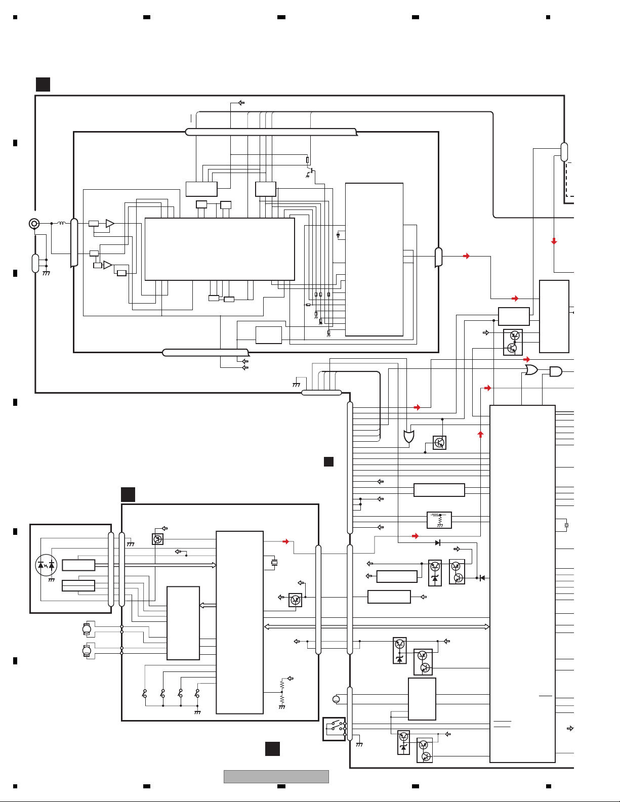
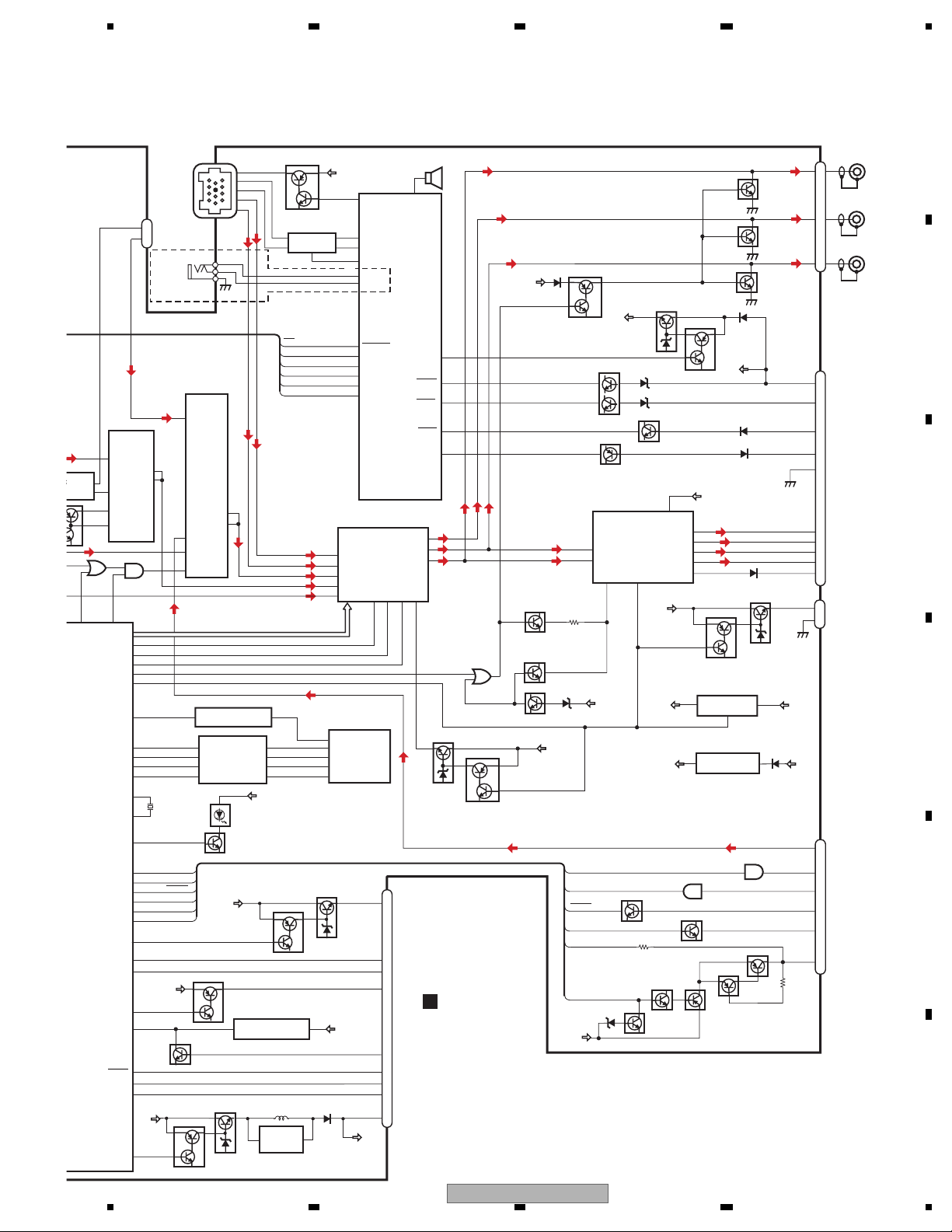
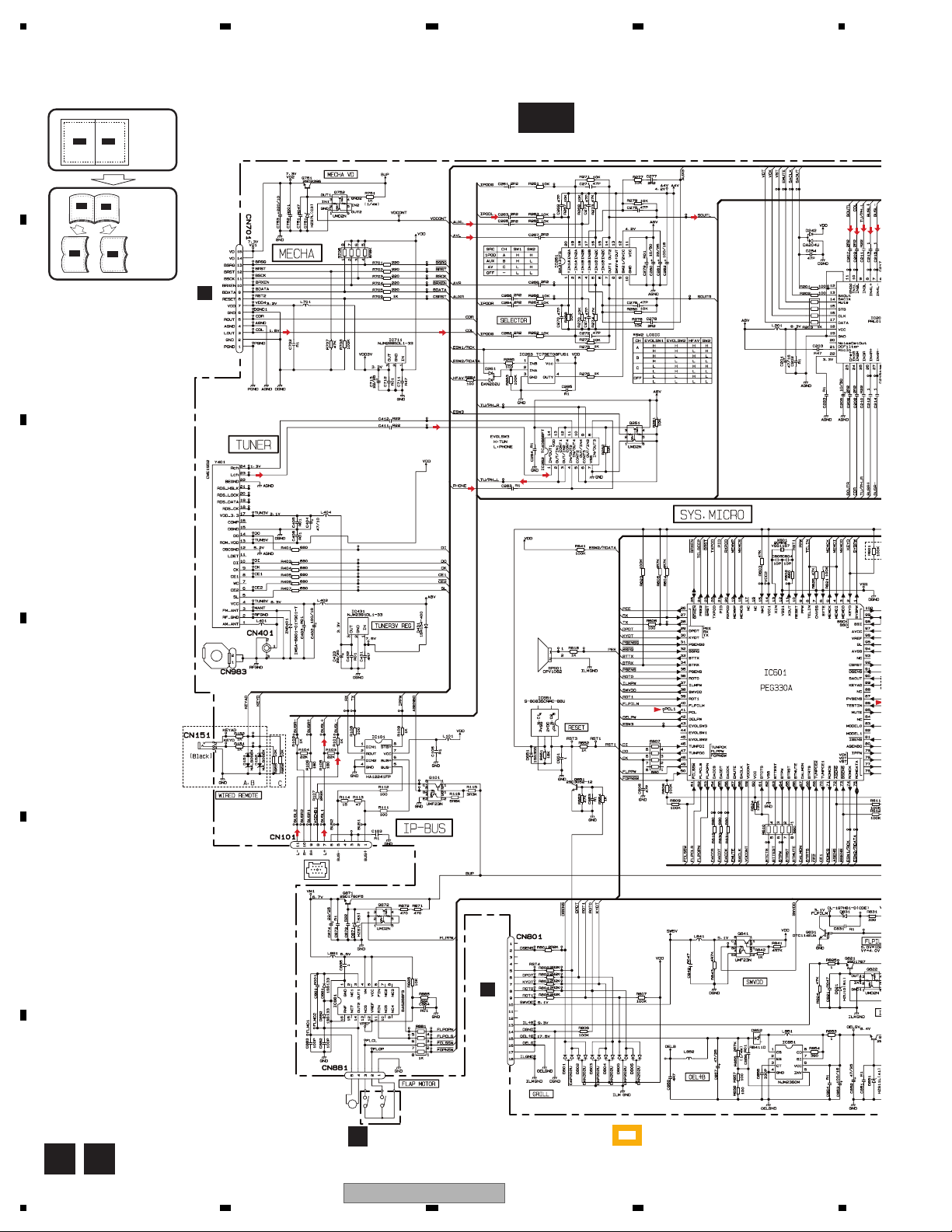
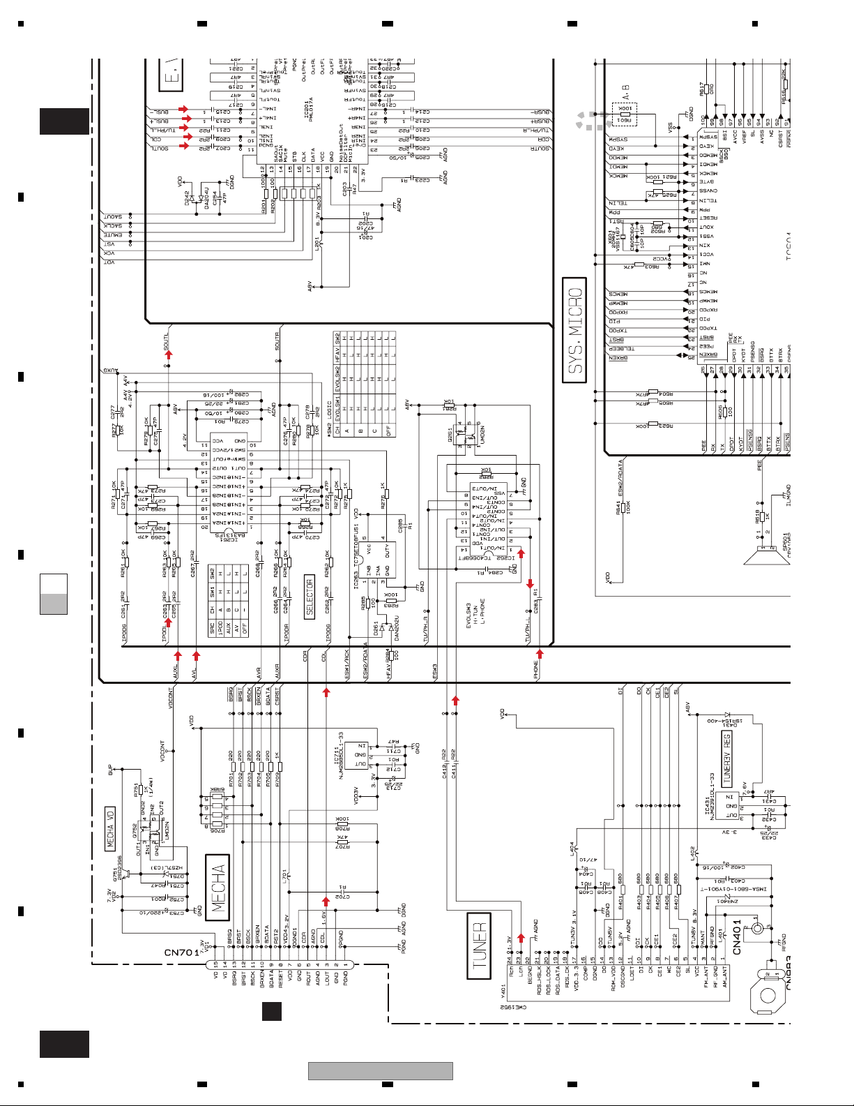
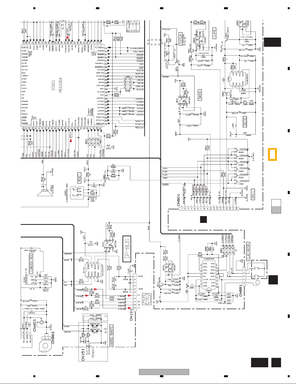
3. BLOCK DIAGRAM AND SCHEMATIC DIAGRAM
3.1 BLOCK DIAGRAM
A
A
TUNER AMP UNIT
VDD
DI
NC
DO
2.5V
ORX
BTPW2
OTX
7
6
1
2
CN76
CN701
LOUT
13
VDD
Q102
VDD
9
/RESET
8
VD
2
VD
1
VD
SWITCH UNIT
NCNCNC
BOOTE
ORST
54
D
M
FLAP
MOTOR
CN522
24
17
15
32
40
39
36
6
7
35
33
34
11
3
1
8
9
10
2
4
12
3
7
14
15
4
5
2
3
1
NC
5
8
CN521
AVL
MICIN
TELOUT
HFAV
ORX
OTX
BOOTE
BTRST
BTMUTE
BTTEST
DACCS
DACDT
DACCK
BTCTS3
BTRX3
BTTX3
BTRTS3
CN701
LOUT
BT5V
BT3V
VDD
RESET
VD
CN881
FLM02
FLM01
FLOP
FLCL
IC 2
2.5V
DET, FM MPX
BT3V REGULATOR
3
NJM2391DL1-33
3
NJM2885DL1-33
BT5V
BT3V
A8V
IC711
9
12
IC461
1
BRST,BRXEN,BSRQ,BDATA,BSCK
MECHA VD
Q751
BA6288FS
14
OUT2 RIN
3
4
VM
5
VCC
Q871
B
CN401
1
2,3
2
1
CN983
C
D
PICKUP UNIT
(P10.5)(SERVICE)
LASER
DIODE
E
F
MONITOR
DIODE
LOAD/
FM/AM TUNER UNIT
1
3
AM ANT
FM ANT
ATT
ATT
ANT adj
FMRF
FMRF
RF adj
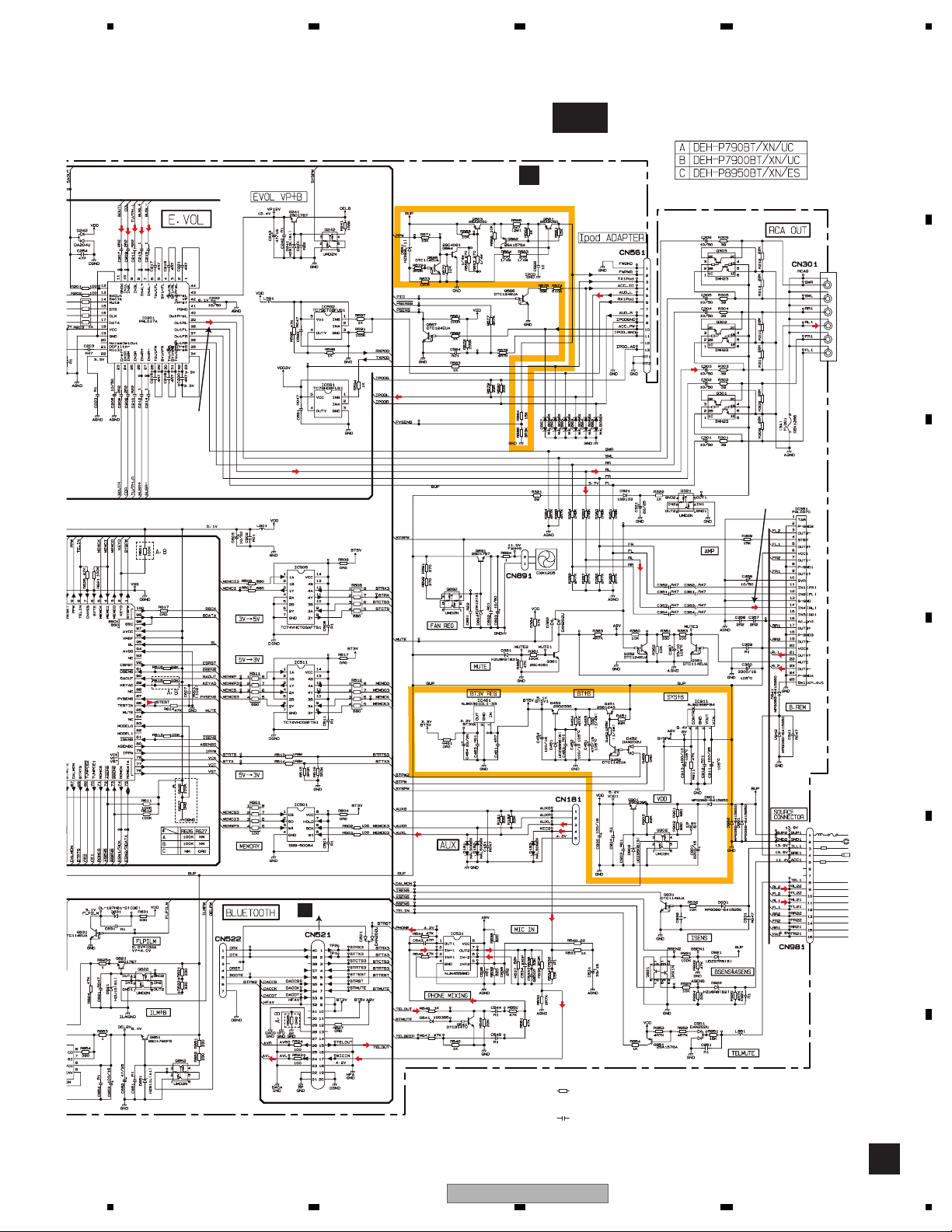
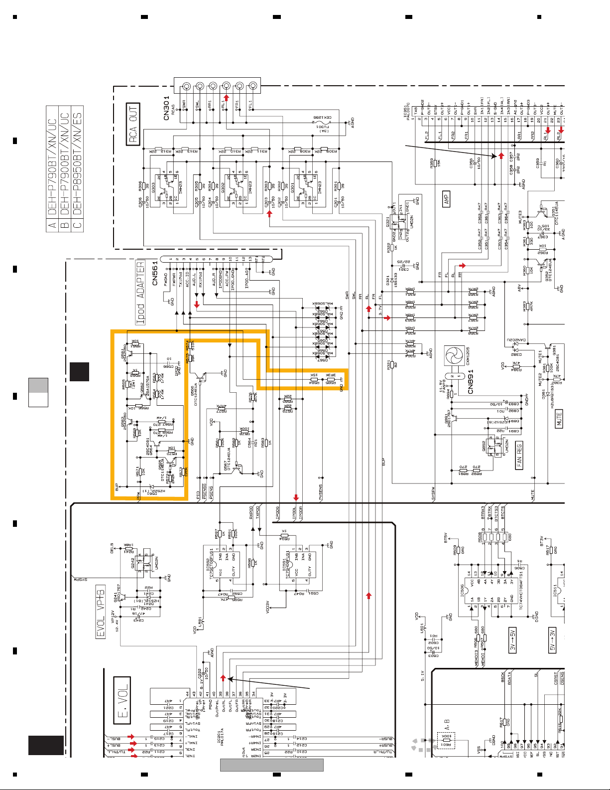
A:DEH-P7900BT/UC
B:DEH-P790BT/UC
C:DEH-P8950BT/ES
CD CORE UNIT(S10.5COMP2)
C
CN101
LD-
15
15
MD
5
5
VREF
FOM
FOP
TOP
TOM
88
FOM
33
FOP
2
2
TOP
1
1
TOM
44
LD+
14
14
S904
12EJ
HOLOGRAM
UNIT
FOCUS ACT.
TRACKING ACT.
SPINDLE
MOTOR
CARRIAGE
MOTOR
M
M
RFGND
OSCGND
212 1522 16 4 17
VDD
Q101
REFO
AC,BD,F,E
CD
DRIVER
IC301
BA5839FP
12
FOM
11
FOP
14
TOP
13
TOM
16
SOP
15
SOM
18
CLCONT
LCOP
17
CONT
LCOM
S905
8EJ
S903
DSCSNS
SL
CK
DO
SL
3.3V
TUN3V
A8V
LOUT
XTAL
/XTAL
/PUEN
/RESET
VDSENS
DI
IC 5
←
5V 3.3V
IC 4
3.3V 2.5V
55
50
52
39
16
11
CK
VCC
CE1
CE1
←
X201
16.93MHz
BRST,BRXEN,BSRQ
BDATA,BSCK
CE2
7 6 13 5 10 9 8 11 14 18 19 20 21
NC
CE2
ROM_VDD
IC 3 EEPROM
5.0V
OSC
LPF
IC 1
3.3V
MIXER, IF AMP
T51
CF52
DGND
LOEJ
AUDIOGNDNCVCC
TD,FD
SD,MD
22
21
9
S901
HOME
VDD_3.3
RF-AMP, CD DECODER,
MP3/WMA DECODER,
DIGITAL SERVO /
DATA PROCESSOR
141
LD
142
PD
133
REFOUT
IC201
PE5547A
5
LOEJ
43
CLCONT
41
CONT
8
12EJ
7
8EJ
6
DSCSNS
9
HOME
F
Lch
23
MUTE
Q541
←
3V 5V
IC506(1/2)
TC74VHCT08AFTS1
←
5V 3V
BUP
BT+B
Q453
1
Q452
VDD
Q752
BUP
IC881
11
6
FINOUT1
AUTO FLAP
MOTOR DRIVE
BUP
Q872
11
Q451
8
A8V
PHONE MIXING
7
2
NJM4558MD
24
PEE2
43
EVOLSW3
65
BTRST
66
BTMUTE
63
BTTEST
54
DACCS
55
DACDT
56
DACCK
61
BTCTS
34
BTRX
33
BTTX
68
BTRTS
CONTROLLER
IC601(1/2)
PEG330A
64
BTPW
92
CDRST
59
VDCONT
52
FLPCLS
53
FLPOPN
50
FOPNSW
51
FCLSSW
49
FLPPW
IC531
ROMCK
SYSTEM
74
Q261
1TUNL
6
1
4
13
5
ROMDATA
SYSPW
MEMCS
MEMWP
MEMDO
MEMCK
FLPILM
RXPOD
PVSENS
SWVDD
OELPW
EMUTE
SAOUT
MEMDI
TXPOD
PSENS
RESET
DSENS
CN181
AUXL
IC262
TC4066BFT
IN/OUT1
OUT/IN1
OUT/IN2
IN/OUT2
CONT1
CONT2
2
1
IC263
TC7SET08F
75
57
58
SACLK
90
85
MUTE
1
4
18
19
3
5
13
XIN
11
XOUT
40
22
20
35
21
PID
9
PPW
87
37
ILMPW
36
ROT0
39
ROT1
38
10
91
29
DPDT
30
KYDT
42
BUP
4
A
3
R
2
3
4
2
18
DEH-P790BT/XN/UC
1234
5 678
A
MIXING
531
558MD
74
ROMCK
TEM
OLLER
1(1/2)
330A
Q261
6
1
13
ROMDATA
MEMWP
PVSENS
CN181
AUXL
IC262
TC4066BFT
1
IN/OUT1
OUT/IN1
OUT/IN2
4
IN/OUT2
CONT1
5
CONT2
2
1
IC263
TC7SET08FUS1
75
57
EMUTE
58
SACLK
90
SAOUT
85
MUTE
1
SYSPW
4
MEMDI
18
MEMCS
19
3
MEMDO
5
MEMCK
13
XIN
11
XOUT
40
FLPILM
22
TXPOD
20
RXPOD
35
PSENS
21
PID
9
PPW
87
37
ILMPW
36
ROT0
39
ROT1
38
SWVDD
10
RESET
91
DSENS
29
DPDT
30
KYDT
BUP
42
OELPW
IP-BUS
4
AUX
3
WIRED
REMOTE
2
3
4
20.000MHz
A,B
X601
TXPOD
RXPOD
PSENS
PPW
PVSENS
VDD
SELECTOR
18
20
16
9
PID
Q852
CN101
CN151
3
2
1
IC261
BA3131FS
+IN2B
14
OUT2
15
-IN2C
+IN2A
+IN2C
SW2
VST,VCK,VDT
←
3V 5V
3
IC506(2/2)
TC74VHCT08AFTS1
←
4
5V 3V
1
IC511
12
TC74VHC08FTS1
9
FLPILM
Q831
BUP
SWVDD
Q841
1
S-80835CNMC-B8U
Q651
OEL+B
Q851
DC-DC CONVERTER
8
5
1
7
11
BUSL-
BUSBUS+
BUSL+
BUSL+
BUSL-
SOUTL
TU/PH_L
CDL
VDD
RESET
IC651
6
NJM2360M
Q101
IP-BUS DRIVER
5
HA12241FP
CE2
CE1
DO
DI
CK
SL
1
6
3
11
8
ILM+B
Q822
IC851
IC101
8
1
7
6
10
8
9
2
SO
1
CS
3
W#
5
SI
6
SCK
Q821
2
BUP
ASENBO
SYSTEM
CONTROLLER
IC601(2/2)
TX
PEG330A
RX
IPPW
KEYD
KEYAD
TUNPCE2
TUNPCE1
TUNPDO
TUNPDI
TUNPCK
SL
IC201
PML017A
Mute
SACLK
14
13
12
26
OutPreL
OutFL
OutRL
SAOut
43
80
1
28
27
26
79
2
89
69
70
47
46
48
95
ELECTRONIC VOLUME/
SOURCE SELECTOR
IN4L+
IN4L-
IN1L
IN3L
IN2L
MEMORY
IC501
S99-50084
CN801
IL+B
13
ROT0
8
ROT1
9
SWVDD
10
VDD
RESET
5
DSENS
2
DPDT
6
KYDT
7
OEL+B
15
OELB
SP601
BUZZER
PEE
DALMON
BSENS
ASENS
ISENS
TELIN
VP
CN1801
40
38
39
B
67
73
72
81
8
Q241
RL
SWL
EVOL VP+B
Q242
FL
BUP
BACKUP SENSE
ACC SENSE
MUTE
Q352
MUTE
Q351
Q381
MUTE
OELB
TXPOD
RXPOD
PVSENS
PPW
BUP
Q321
Q921
TEL MUTE
12
14
VDD
Q951
POWER AMP
IN2(FL)
IN4(RL)
22
BUP
SYSPW
TC7SET08FUS1
Q565
Q931
ILM SENSE
IC351
PAL007C
STBYMUTE
4
IC592
Q567
VDD REGULATOR
Q901
Q902
6,20
VCC1,VCC2
5
OUT2+
3
OUT2-
21
OUT4+
23
OUT4-
25
Switch_out
BUP
SYS+B REGULATOR
2
A8V
3
TUN3V
NJM2391DL1-33
TC7SH08FUS1
Q566
Q564
Q563
BUP
BUP
FAN REG
Q892
IC911
NJM2388F84
4
TUNER 3V
REGULATOR
IC431
IC591
14
Q562
Q891
Q561
1
1
Q302
Q303
Q301
SWL
RL
FL
CN301
CN981
BUP1
ACC1
TEL1
GND1
FL22
RL21
RL22
BRE1
CN891
BUP
A8V
CN561
AUD_LIPODL
TXiPod41
RXiPod
ACC-PWPSENS
ACC-IDPID
FWPWR
ILL1
FL21
5
9
1
1
5
3
8
2
SOURCE
CONNECTOR
12
10
11
9
4
2
FAN
1
5
3
6
iPod
10
ADAPTER
4
2
RCA OUT
B
C
D
E
F
56
DEH-P790BT/XN/UC
7
8
19
1234
A
B
A
CN801
B
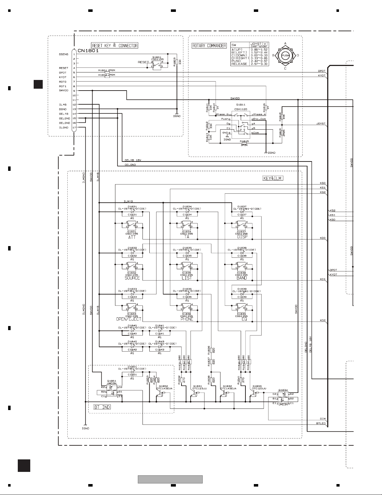
KEYBOARD UNIT
CN1801
IL+B
12
ROT0
7
ROT1
8
SWVDD
9
REMOTE CONTROL
OPT IN
DPDT
5
KYDT
6
DSENS
1
14
4
RESET
S1801
RESET
SWVDD
SENSOR
IC1931
GP1UX31RK
OEL+B
1,3
3
1
3V REGULATOR
IC1951
S-1200B33-M5
ROTARY COMMANDER
S1811
5
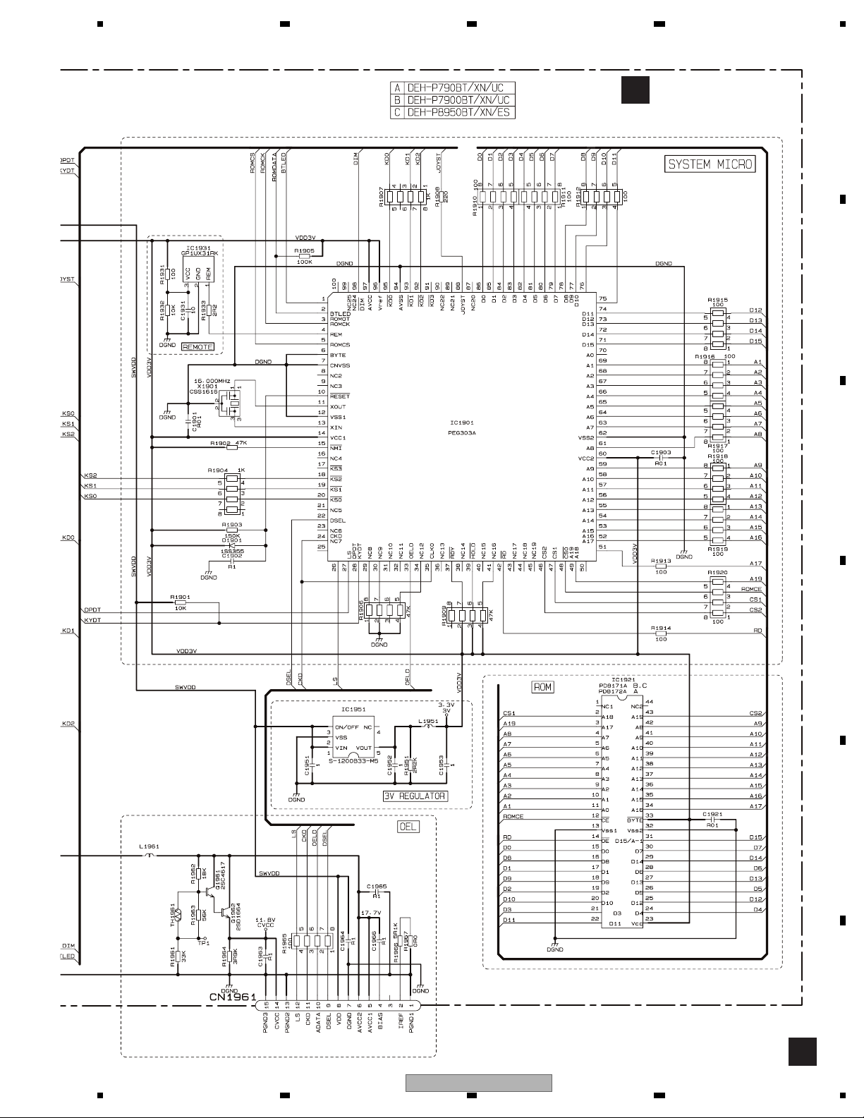
ROM
23
VCC
33
BYTE
IC1921
:PD8171A
A,C
:PD8172A
B
KEY MATRIX
S1831-S1839
IC1901
PEG303A
KD0-2,KS0-2
BTLED
XOUT
CLK0
OELD
DSEL
DIM
XIN
LS
CKD
KEY/OEL CONTROLLER
88
JOYST
JOYST
60
VCC2
14
VCC1
97
AVCC
96
Vref
4
REM
27
DPDT
28
KYDT
12
48
CSO
CE
2
47
A18
A19
OE
43
14
DATA
ADDRESS
CS1
46
CS2
42
RD
SWVDD
1
98
13
11
26
24
35
33
22
X1901
16MHz
Q1851
OEL+B
BT IND
(ILLUMINATION)
Q1961
Q1852
Q1834
Q1962
Q1831-Q1833
SWVDD
SWVDD
OEL+B
CN1961
CKD
ADATA
DSEL
VDD
AVCC 1
AVCC 2
CVCC
LS
12
11
10
9
8
OEL UNIT
5
6
14
C
A:DEH-P7900BT/UC
B:DEH-P790BT/UC
C:DEH-P8950BT/ES
D
E
F
20
1234
DEH-P790BT/XN/UC

5 678
D
BLUETOOTH UNIT
ANTENNA
E
ANTENNA
ANT1101
ANT1102
2,3
CN1
1
BLUETOOTH MODULE
SIOF_TXD
SIOF_SCK
SIOF_SYNC
Y1
SIOF_RXD
A5
RF_I/O
RESETP
REG_OUT
VCC_RF
SIOF_SS2
SCIF1_CTS
SCIF1_RTS
SCIF1_RXD
SCIF1_TXD
SCIF0_RXD
SCIF0_TXD
BOOT_E
SCIF0_CTS
SCIF0_RTS
SIOF_MCLK
SCO_CLK_OUT
SIOF_SS1
PTB1
DATAO
BCK
LRCK
MCK
N2
DATAI
Q2
G8
G9
P1
I1
I2
H2
H3
E2
E3
Q1
F1
F2
O1
MCK
L1
HFMCK
HFAV
O3
T3
DAC
IC56
PCM1742KE
2N3
DATA
1N1
BCKIN
3O2
LRCKIN
16
MCLK
CODEC
3
BCLK
4
DR
5
FS
2
DX
IC36
AK2301A
CLOCK SELECT
IC21
TC74VHC02FTS1
11
4A
4
2Y
12
4B
2
1A
3
1B
Vout L
MD
MC
ML
GSR
VFTN
MUTEN
RSTN
TC7PAU04FU
6
3
X21 11.2896MHz
TC7PAU04FU
6
3
X22 12.288MHz
13
14
15
7
15
23
22
OSC
IC22
OSC
IC23
VCC
VCC
HFAV
FSCHG
37
NJM4558V
5
AN6123MS
Q37
Q36
Q1
Q2
5
1
4
5
1
4
LPF
IC66
ALC
IC51
A
B
BT3V
D3V
D5V
A8V
CN76
AUDIO L
DACDT
DACCK
DACCS
TELOUT
MICIN
BTMUTE
BTRST
BTTEST
BTRTS
BTCTS
BTTX
BTRX
ORX
OTX
BOOTE
OCTS
ORTS
HFAV
24
33
34
35
15
17
7
6
A
CN521
5
4
3
2
1
40
39
36
38
37
8
9
10
11
12
32
1,2
3
Q21
BT3V
C
Q23
BT3V
Q22
D
E
F
56
DEH-P790BT/XN/UC
7
8
21
1234
A-a
A-b
A-a
A-b
A-b
A-a
p
3.2 OVERALL CONNECTION DIAGRAM(GUIDE PAGE)
Note: When ordering service parts, be sure to refer to " EXPLODED VIEWS AND PARTS LIST" or
"ELECTRICAL PARTS LIST".
A
A-a
A-a
A-a
A-b
A-b
A-b
Large size
SCH diagram
Guide page
Detailed page
+2.2dBs
+3.01dBs
A-a
(ipod video:0dB play)
+1.3dBs
B
C
D
C
CN701
FM/AM TUNER UNIT
(0dB play)
+2.2dBs
(0dB play)
+0.6dBs
FM(30%):-24dBs
AM(30%):-24dBs
i
E
F
A F
22
B
CN1801
M
M3
FLAP MOTOR
XXA7400
F
CSN1052
S2 CLOSE
CSN1051
S1 OPEN
SW UNIT
: The power supply is shown with the marked box.
DEH-P790BT/XN/UC
1234
5 678
FM(30%): -0.9dBs
AM(30%): -0.9dBs
IP-BUS: +14.3dBs
CD: +13.7dBs
BT TEL: +13.1dBs
BT AV:+14.11dBs
AUX: +14.3dBs
ipod(video): +14.4dBs
A-b
TUNER AMP UNIT
A
FAN
>
FM(30%): +21.1dBs
AM(30%): +21.1dBs
IP-BUS: +36.3dBs
CD: +35.7dBs
BT TEL: +35.1dBs
BT AV:+36.11dBs
AUX: +36.3dBs
ipod(video): +36.4dBs
A
B
C
D
>
CEK1136
10A
B.UP
GND
1K(1/2W)
ILL
B.REM
1K(1/2W)
ACC
TEL
RL-
FL-
RL+
CN76
D
-5dBs
NOTE :
Symbol indicates a resistor.
No differentiation is made between chip resistors and
discrete resistors.
.
The > mark found on some component parts indicates the importance of the safety factor of the part.
Therefore, when replacing, be sure to use parts of identical designation.
Symbol indicates a capacitor.
No differentiation is made between chip capacitors and
discrete capacitors.
Decimal points for resistor
and capacitor fixed values
are expressed as :
2.2
t
2R2
0.022
t
R022
FL+
RR-
FR-
RR+
FR+
E
F
A
56
DEH-P790BT/XN/UC
7
8
23
1234
A
>
CD: +35.7dBs
AUX: +36.3dBs
BT AV:+36.11dBs
IP-BUS: +36.3dBs
BT TEL: +35.1dBs
FM(30%): +21.1dBs
AM(30%): +21.1dBs
B
ipod(video): +36.4dBs
C
TUNER AMP UNIT
FAN
A
A-a A-b
D
E
F
A-b
24
CD: +13.7dBs
AUX: +14.3dBs
BT AV:+14.11dBs
IP-BUS: +14.3dBs
BT TEL: +13.1dBs
FM(30%): -0.9dBs
AM(30%): -0.9dBs
ipod(video): +14.4dBs
1
DEH-P790BT/XN/UC
1234

5 678
FR-
FR+
FL+
RR+
RR-
R022
t
2R2
t
and capacitor fixed values
are expressed as :
2.2
0.022
Decimal points for resistor
A
>
B.UP
10A
CEK1136
GND
ILL
B.REM
1K(1/2W)
ACC
1K(1/2W)
FL-
RL+
RL-
TEL
B
CN76
D
-5dBs
Symbol indicates a resistor.
No differentiation is made between chip resistors and
discrete resistors.
Symbol indicates a capacitor.
NOTE :
No differentiation is made between chip capacitors and
discrete capacitors.
C
A-a A-b
D
E
2
DEH-P790BT/XN/UC
56
The > mark found on some component parts indicates the importance of the safety factor of the part.
Therefore, when replacing, be sure to use parts of identical designation.
A-b
F
7
8
25
A
+
+
+
+
+
B
A-b
1234
CD:
AUX:
BT AV:+1
IP-BUS:
BT TEL:
FM(30%):
AM(30%):
ipod(video):
1
C
A-bA-a
(ipod video:0dB play)
D
E
+1.3dBs
+2.2dBs
+3.01dBs
(0dB play)
+0.6dBs
FM(30%):-24dBs
AM(30%):-24dBs
F
A-a
26
FM/AM TUNER UNIT
C
CN701
DEH-P790BT/XN/UC
1234
5 678
M
The > mTherefor
A
2
A-b
B
: The power supply is shown with the marked box.
+2.2dBs
(0dB play)
B
CN1801
M
M3
CSN1051
S1 OPEN
CSN1052
S2 CLOSE
XXA7400
FLAP MOTOR
C
A-bA-a
D
SW UNIT
F
E
F
A-a
F
DEH-P790BT/XN/UC
56
7
8
F
27
1234
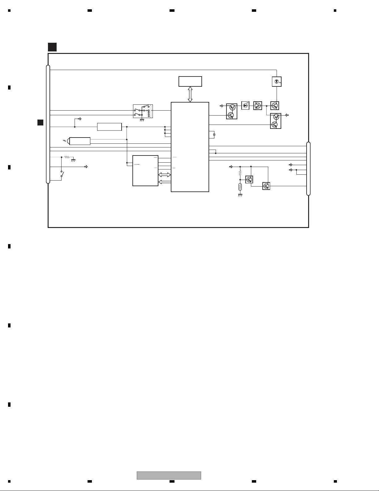
3.3 KEYBOARD UNIT
A
A
CN801
B
C
D
E
F
B
28
1234
DEH-P790BT/XN/UC
5 678
KEYBOARD UNIT
B
A
B
C
D
E
OEL UNIT
56
MXS8231
DEH-P790BT/XN/UC
F
B
7
8
29
1234
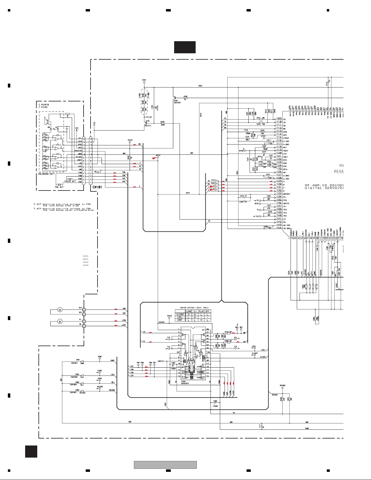
3.4 CD MECHANISM MODULE(GUIDE PAGE)
A
C-a
PICKUP UNIT(P10.5)(SERVICE)
B
F
T
F
T
F
F
T
T
F
F
T
T
C
%
F
F
T
T
#
@
SWITCHES:
CD CORE UNIT(S10.5COMP2)
S901:HOME SWITCH..........ON-OFF
S903:DSCSNS SWITCH......ON-OFF
S904:12EJ SWITCH.............ON-OFF
S905:8EJ SWITCH...............ON-OFF
The underlined indicates the switch position.
D
M1 CXC7134
SPINDLE MOTOR
M2 CXC4026
LOADING/CARRIAGE MOTOR
E
3
2
1
S
S
C
C
T
9
F
0
F
F
T
T
$
S
7
C
4
8
5
S
S
C
C
CD DRIVER
F
C
30
1234
DEH-P790BT/XN/UC
 Loading...