

Pioneer DEH-1700 Service manual
PIONEER CORPORATION 1-1, Shin-ogura, Saiwai-ku, Kawasaki-shi, Kanagawa 212-0031, Japan
PIONEER ELECTRONICS (USA) INC. P.O. Box 1760, Long Beach, CA 90801-1760, U.S.A.
PIONEER EUROPE NV Haven 1087, Keetberglaan 1, 9120 Melsele, Belgium
PIONEER ELECTRONICS ASIACENTRE PTE. LTD. 253 Alexandra Road, #04-01, Singapore 159936
PIONEER CORPORATION 2014
CD RDS RECEIVER
ORDER NO.
CRT5572
DEH-1700UB/XNEW5
DEH-1700UB
DEH-1700UBA/XNEW5
DEH-1700UBB/XNEW5
DEH-1700UBG/XNEW5
This service manual should be used together with the following manual(s):
Model No. Order No. Mech. Module Remarks
CX-3287
CRT4759 S11.6STD CD Mech. Module : Circuit Descriptions, Mech. Descriptions, Disassembly
/XNEW5
K-ZZZ JULY 2014 Printed in Japan
1234
1234
C
D
F
A
B
E
SAFETY INFORMATION
Where in a manufacturer’s service documentation, for example in circuit diagrams or lists
of components, a symbol is used to indicate that a specific component shall be replaced only
by the component specified in that documentation for safety reasons, the following symbol shall
be used:
This service manual is intended for qualified service technicians; it is not meant for the casual do-it-yourselfer.
Qualified technicians have the necessary test equipment and tools, and have been trained to properly and safely repair
complex products such as those covered by this manual.
Improperly performed repairs can adversely affect the safety and reliability of the product and may void the warranty.
If you are not qualified to perform the repair of this product properly and safely, you should not risk trying to do so
and refer the repair to a qualified service technician.
CAUTION:
USE OF CONTROLS OR ADJUSTMENTS OR PERFORMANCE OF PROCEDURES OTHER THAN THOSE
SPECIFIED HEREIN MAY RESULT IN HAZARDOUS RADIATION EXPOSURE.
- Safety Precautions for those who Service this Unit.
When checking or adjusting the emitting power of the laser diode exercise caution in order to get safe, reliable
results.
Caution:
1. During repair or tests, minimum distance of 13 cm from the focus lens must be kept.
2. During repair or tests, do not view laser beam for 10 seconds or longer.
WARNING!
The AEL (accessible emission level )of the laser power output is less than CLASS 1
but the laser component is capable of emitting radiation exceeding the limit for
CLASS 1.
A specially instructed person should do servicing operation of the apparatus.
Laser diode characteristics
Wave length : 785 nm to 814 nm
Maximum output : 1 190 µW(Emitting period : unlimited)
Additional Laser Caution
Transistors Q101 in PCB drive the laser diodes.
When Q101 is shorted between their terminals, the laser diodes will radiate beam.
If the top cover is removed with no disc loaded while such short-circuit is continued,
the naked eyes may be exposed to the laser beam.
CAUTION
This product is a class 1 laser product classified under the Safety of laser products, IEC
60825-1:2007.
2
DEH-1700UB/XNEW5

5678
56
7
8
C
D
F
A
B
E
CONTENTS
SAFETY INFORMATION .....................................................................................................................................2
1. SERVICE PRECAUTIONS ................................................................................................................................4
1.1 SERVICE PRECAUTIONS .........................................................................................................................4
1.2 NOTES ON SOLDERING...........................................................................................................................4
2. SPECIFICATIONS.............................................................................................................................................5
2.1 SPECIFICATIONS ......................................................................................................................................5
2.2 DISC/CONTENT FORMAT .........................................................................................................................5
3. BASIC ITEMS FOR SERVICE ..........................................................................................................................6
3.1 CHECK POINTS AFTER SERVICING .......................................................................................................6
3.2 PCB LOCATIONS .......................................................................................................................................6
3.3 JIGS LIST ...................................................................................................................................................7
3.4 CLEANING .................................................................................................................................................7
4. BLOCK DIAGRAM ............................................................................................................................................8
4.1 BLOCK DIAGRAM......................................................................................................................................8
4.2 POWER BLOCK DIAGRAM .....................................................................................................................10
5. DIAGNOSIS ....................................................................................................................................................11
5.1 OPERATIONAL FLOWCHART.................................................................................................................11
5.2 ERROR CODE LIST.................................................................................................................................12
5.3 CONNECTOR FUNCTION DESCRIPTION .............................................................................................14
6. SERVICE MODE.............................................................................................................................................15
6.1 DISPLAY TEST MODE 1 ..........................................................................................................................15
6.2 DISPLAY TEST MODE 2 ..........................................................................................................................16
6.3 SOFTWARE VERSION UP METHOD......................................................................................................17
6.4 CD TEST MODE.......................................................................................................................................18
7. DISASSEMBLY ...............................................................................................................................................19
8. EACH SETTING AND ADJUSTMENT............................................................................................................25
8.1 CD ADJUSTMENT ...................................................................................................................................25
8.2 CHECKING THE GRATING AFTER CHANGING THE PICKUP UNIT ....................................................26
8.3 PCL OUTPUT CONFIRMATION...............................................................................................................28
9. EXPLODED VIEWS AND PARTS LIST ..........................................................................................................30
1 PACKING ..................................................................................................................................................30
9.
9.2 EXTERIOR ...............................................................................................................................................32
9.3 CD MECHANISM MODULE .....................................................................................................................34
10. SCHEMATIC DIAGRAM................................................................................................................................36
10.1 TUNER AMP UNIT (1/2 scale) ...............................................................................................................36
10.2 KEYBOARD UNIT ..................................................................................................................................38
10.3 CD CORE UNIT (S11.6VA) ....................................................................................................................40
10.4 WAVEFORMS.........................................................................................................................................42
11. PCB CONNECTION DIAGRAM....................................................................................................................44
11.1 TUNER AMP UNIT .................................................................................................................................44
11.2 KEYBOARD UNIT ..................................................................................................................................48
11.3 CD CORE UNIT (S11.6VA) ....................................................................................................................50
12. ELECTRICAL PARTS LIST ...........................................................................................................................52
DEH-1700UB/XNEW5
3

1234
1234
C
D
F
A
B
E
1. SERVICE PRECAUTIONS
1. You should conform to the regulations governing the product (safety, radio and noise, and other
regulations), and should keep the safety during servicing by following the safety instructions
described in this manual.
2. Before disassembling the unit, be sure to turn off the power. Unplugging and plugging the connectors
during power-on mode may damage the ICs inside the unit.
3. To protect the pickup unit from electrostatic discharge during servicing, take an appropriate treatment
(shorting-solder) by referring to "the DISASSEMBLY".
4. After replacing the pickup unit, be sure to check the grating.
5. Be careful in handling ICs. Some ICs such as MOS type are so fragile that they can be damaged by
electrostatic induction.
For environmental protection, lead-free solder is used on the printed circuit boards mounted in this unit.
Be sure to use lead-free solder and a soldering iron that can meet specifications for use with lead-free solders for repairs
accompanied by reworking of soldering.
Compared with conventional eutectic solders, lead-free solders have higher melting points, by approximately 40 C.
Therefore, for lead-free soldering, the tip temperature of a soldering iron must be set to around 373 C in general, although
the temperature depends on the heat capacity of the PC board on which reworking is required and the weight of the tip of
the soldering iron.
Compared with eutectic solders, lead-free solders have higher bond strengths but slower wetting times and higher melting
temperatures (hard to melt/easy to harden).
The following lead-free solders are available as service parts:
Parts numbers of lead-free solder:
GYP1006 1.0 in dia.
GYP1007 0.6 in dia.
GYP1008 0.3 in dia.
1.1 SERVICE PRECAUTIONS
1.2 NOTES ON SOLDERING
4
DEH-1700UB/XNEW5
5678
56
7
8
C
D
F
A
B
E
For all items except the backup current, refer to the Owner's Manual.
Backup current......................... 4.0 mA or less
2. SPECIFICATIONS
2.1 SPECIFICATIONS
2.2 DISC/CONTENT FORMAT
DEH-1700UB/XNEW5
5
1234
1234
C
D
F
A
B
E
3. BASIC ITEMS FOR SERVICE
demrifnocebotmetIserudecorP.oN
1 Confirm whether the customer complain has
been solved.
If the customer complain occurs with the
specific media, use it for the operation check.
The customer complain must not be
reappeared.
Display, audio and operations must be
normal.
2 CD Play back a CD.
(Track search)
No malfunction on display, audio and
operation.
3 FM/AM tuner Check FM/AM tuner action.
(Seek, Preset)
Switch band to check both FM and AM.
Display, audio and operations must be
normal.
4 Check whether no disc is inside the product. The media used for the operating check must
be ejected.
retfaecnaraeppastinotridrosehctarcsoNkcehcecnaraeppA5
receiving it for service.
Item to be checked regarding audio
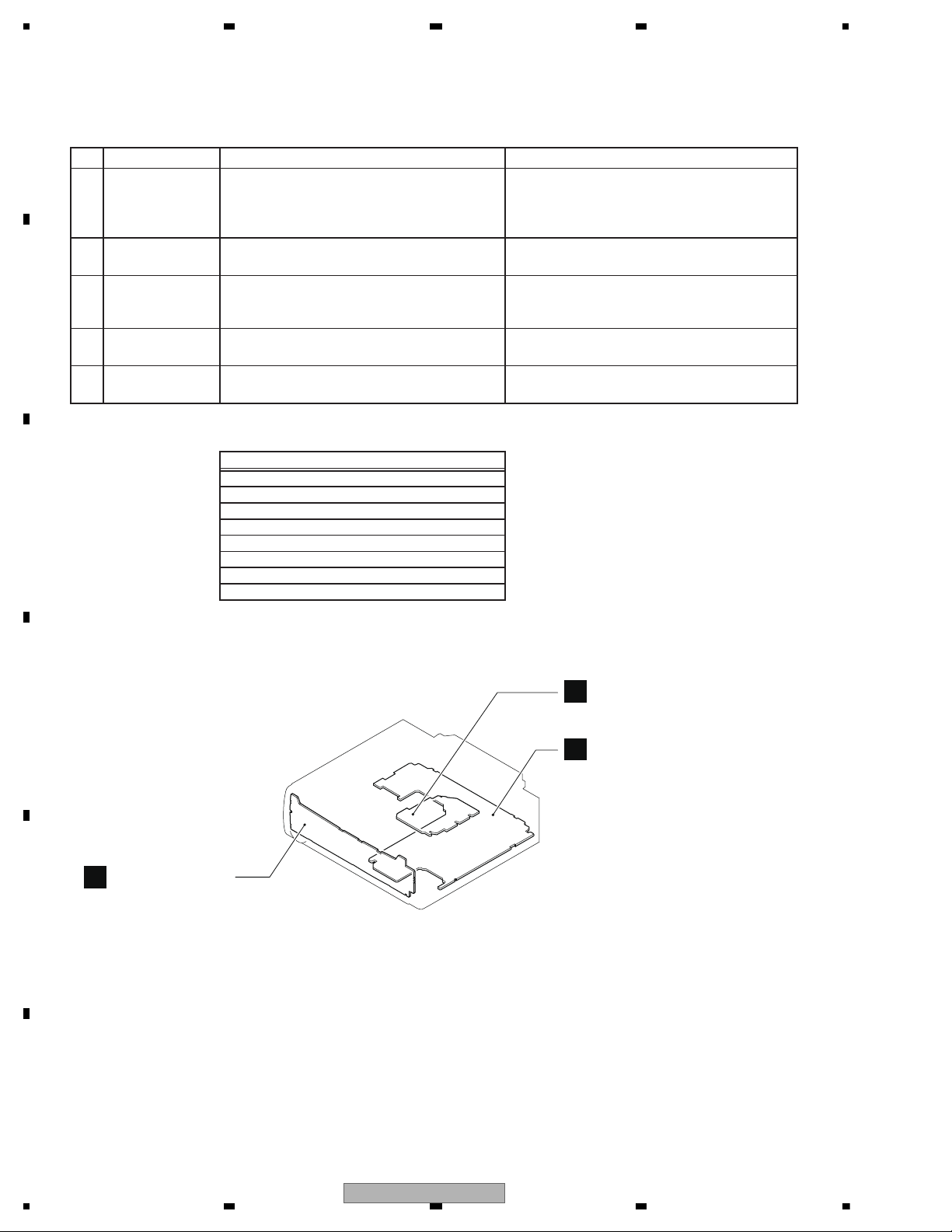
A
B
Keyboard Unit
Tuner Amp Unit
C
CD Core Unit (S11.6VA)
A:DEH-1700UB/XNEW5
B:DEH-1700UBA/XNEW5
C:DEH-1700UBB/XNEW5
D:DEH-1700UBG/XNEW5
Unit Name : Tuner Amp Uni
Unit Number : QWM3898(A)
Unit Number : QWM3900(B)
Unit Number : QWM3901(C)
Unit Number : QWM3899(D)
Unit Name : Keyboard Unit
Unit Number : (A)
Unit Number : (B)
Unit Number : (C)
Unit Number : (D)
Unit Name : CD Core Unit(S11.6VA)
Unit Number : CWX4269
3.1 CHECK POINTS AFTER SERVICING
To keep the product quality after servicing, please confirm following check points.
See the table below for the items to be checked regarding audio:
Distortion
Noise
Volume too low
Volume too high
Volume fluctuating
Sound interrupted
3.2 PCB LOCATIONS
6
DEH-1700UB/XNEW5
5678
56
7
8
C
D
F
A
B
E
- Jigs List
- Grease List
Name
Grease
Grease
Grease No.
GEM1024
GEM1043
Remarks
CD Mechanism Module
CD Mechanism Module
e
G
.
ks
Name
16P FFC
Test Disc
L.P.F.
Jig No.
GGD1310
TCD-782
Remarks
Tuner Amp Unit - CD Core Unit
Checking the grating
Checking the grating (Two pieces)
Before shipping out the product, be sure to clean the
following portions by using the prescribed cleaning
tools:
Portions to be cleaned Cleaning tools
CD pickup lenses Cleaning liquid : GEM1004
Cleaning paper : GED-008
3.3 JIGS LIST
Nam
3.4 CLEANING
rease No
emar
DEH-1700UB/XNEW5
7
1234
1234
C
D
F
A
B
E
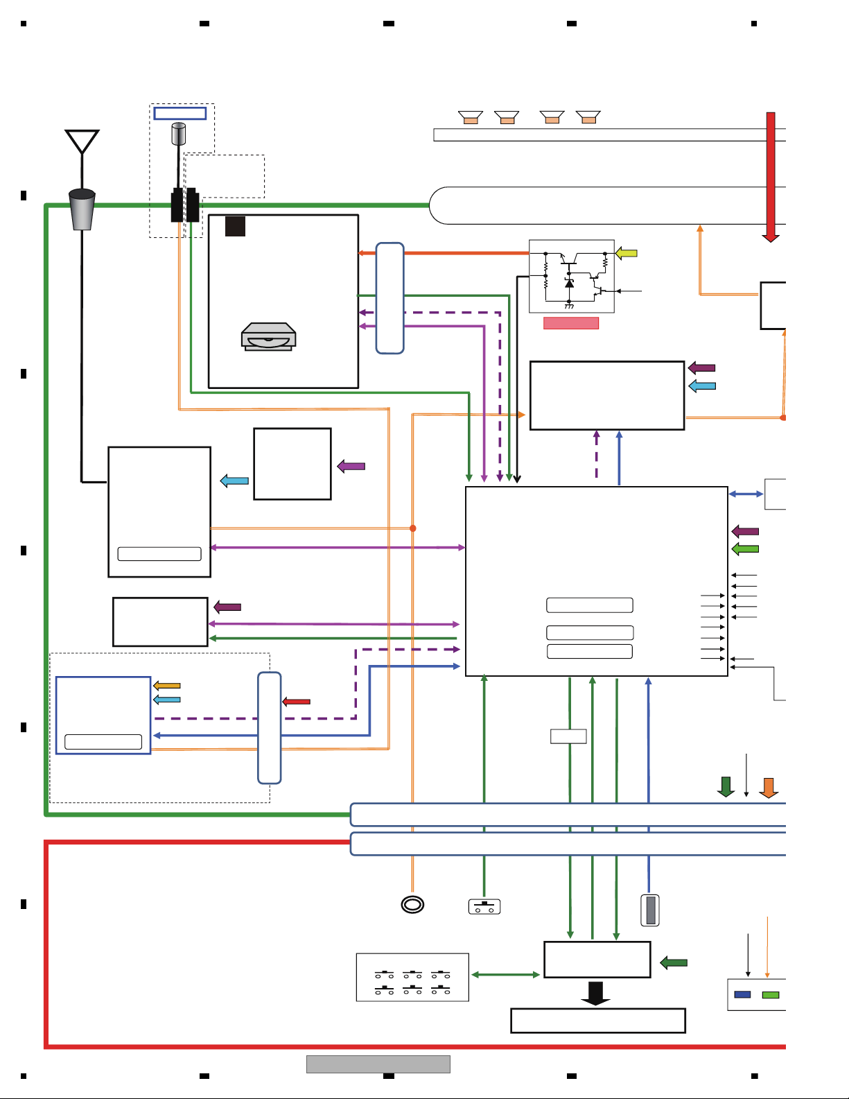
4. BLOCK DIAGRAM
Memory: 64Kbyte
ASENS
BSENS
BTPW
VDSEN
SW5VCONT
A.ANT
ILMPW
TEL.IN
SYSPW
VDCONT
MUTE
ILMPW,DIM
ANTSE
DBTPW
BTPW D
SYSTEM
R5S726A0D216FP
LCD
Display System
PD6586A8
key matrix
SWVDD
SWVDD ILM+B
3→5
KYDT
DPDT
DP,DM
iPod CP
337S3959
CP_SCL,CP_SD
CPPW,CPRST
VDD3
VDD1
VDD
E.VOL JASPER
PM 9013A
Lithio
(TEF6686HN)
X-8086
TUN 3.3V
SYS+B 5.75
VDD3.3V
Suntec BT modual
X-8075
TUNSCL,TUNSDA
MCLK,LRCLK
DATA,CLK
LRCLK,BCLK,DATA
DDCON 5V
MACHA VD
VD CONT
VD SENS
B.up
VD
TUNL TUNR
USB
NRST_CPU
SYSTOBT,BTTPSYS
7.4V
AUX
SOURC
KEYD,KEYAD
RESETB,STB
BCLK,DIN
SINGLE L
LIGTH DISP
FL FRRL/SW RR/SW
ROT0,ROT1
CN1931
1. DGND
2. ILMGND
3. SWVDD
4. ROT1
5. ILM+B
6. ROT0
7. USBGND
8. KYDT
9. USBGND
10. DPDT
11. USB5V
Connector CN 801
Connector CN1931
CN 971
1. GND
2. MICIN
3. GND
4. MICIP
5. GND
6. BTTOSYS
7. SYSTOBT
8. NRST_CPU
9. GND
10. BTLRCK
11. BTBCK
12. BTDATA
13. GND
14. GND
15. VCC
16. VCC
Connector BT
Connector flex
CD_SCL,CD_SDA
BLCK.DATA,LRCK
Connector flex
1. VD
2. VD
3. /CDSRQ
4. CDSTBY
5. SCL
6. SKIP
7. SDA
8. RESET
9. VDD
10. GND
11. DATA
12. BCLK
13. LRCK
14. GND
15. PGND
16. WAIT
CD S11.6 STD
WIRED REMOTE
JA901
Power Connector
BUP
ACC
1. FL+
2. FR+
3. FL-
4. FR-
5. RL+
6. RR+
7. RL-
8. RR-
9. TEL
10. NC
11. ILL
12. NC
13. ACC
14. BREM &
A.ANT
15. B.UP
16. GND
17. GND
18. B.UP
ANT
X401 9.216MHz
X100 26MHz
X603 16.93MHz
X601 12MHz
SW 5V
DC to DC
converter
5V to 3.3V
(MM3571A33P)
Q751 KTD2092(QR)
Q752
RN4983
BT 1.8V
BT 3.3V
For BT modual
X602 16.93MHz
Except BT modual
BT MIC
S-
CDSKIP,CDRST
CDSRQ,CDSTBY
CXK5805
IC451
IC401
IC531
IC601
IC201
IC1801
V1801
JA891
NM
B
NM
NM
JA401
CD CORE UNIT
C
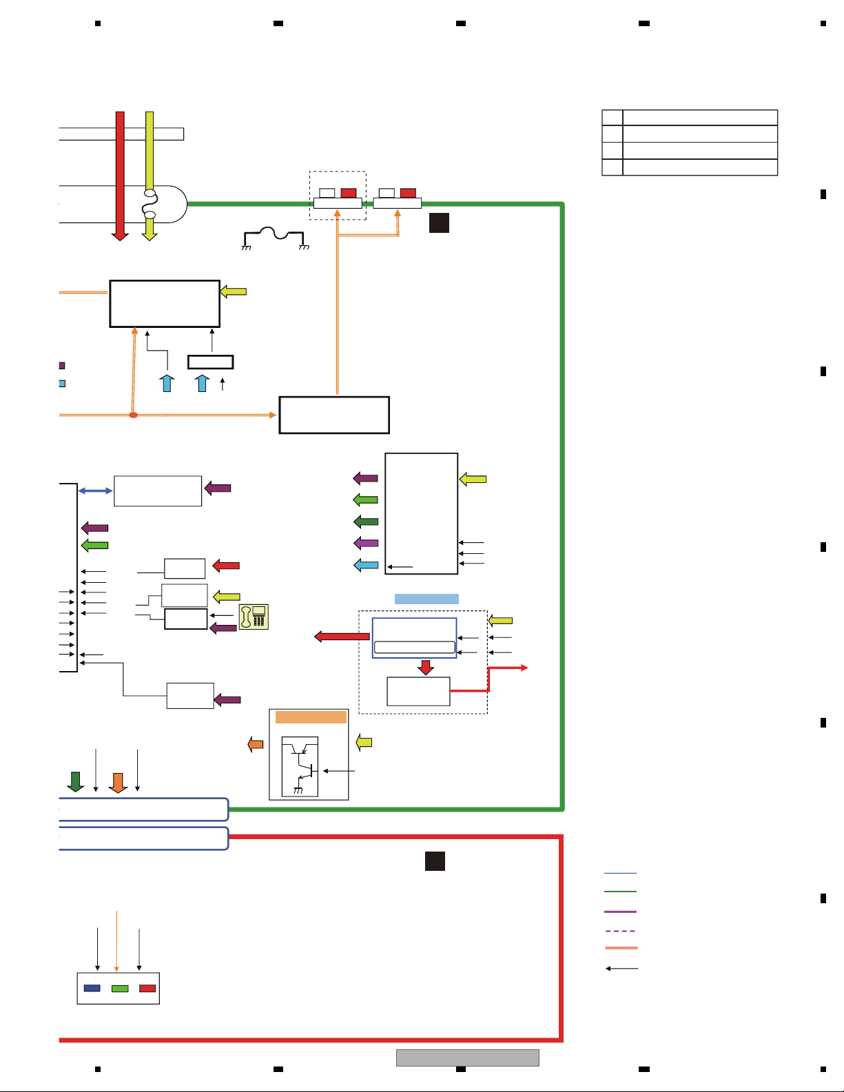
4.1 BLOCK DIAGRAM
8
DEH-1700UB/XNEW5
5678
56
7
8
C
D
F
A
B
E
ASENS
BSENS
VDSENS
A.ANT
TEL.IN
ANTSENS
Digital Line
I2S communication line
Communication Line
Audio Line
I2C Communication line
Control line
DIMBTPW
BTPW DIM
VDD1.2V
SW5V
SYS+B
SWVDD
VDD 3.3V
IC REGULATOR
BA49183-V12
BSENS
B.up
VDCONT
SW5VCONT
SYSPW
B.up
A.SENS
ACC
SWVDD ILM+B
VDD3.3V
VDD1.2V
SYS+B 5.75
VDD3.3V
High side
RCA MUTE
IC POWER AMP
PAL013A
STBY
B.up
SYNC
SYS+B
MUTE
STBY
MUTE
ANT PW
B.up
ILMPW
DD ON
DD con
KBD9876EFJ
ILM+B
USB5V
DDCON 5V TO BT
EN
SYNC
USB&USB5V
SINGLE LED
LIGTH DISPLAY
SYS+B
RESET
VDD
B.up
TELIN
DDCON 5V
VDD
3. SWVDD
4. ROT1
5. ILM+B
6. ROT0
7. USBGND
8. KYDT
9. USBGND
10. DPDT
11. USB5V
12. BTPW
13. DM
14. DIMMER
15. DP
16. AUXGND
17. AUXR
18. SOURCE
19.AUXL
20.DSENS
B.UP
ACC
10A
Q873 2SD1767(QR)
LED SUPPLY
367.347/439.024kHz
GND
RCA GND
P251
CEK1386
YEK5001-A
S-Quad Flash
VDD
PEB155A8
3A
L
R
F
L
R
R/SW
IC301
IC911
IC551
IC681
NM
JA251
TUNER AMP UNIT
A
KEYBOARD UNIT
B
A DEH-1700UB/XNEW5
B DEH-1700UBA/XNEW5
C DEH-1700UBB/XNEW5
D DEH-1700UBG/XNEW5
DEH-1700UB/XNEW5
9
1234
1234
C
D
F
A
B
E
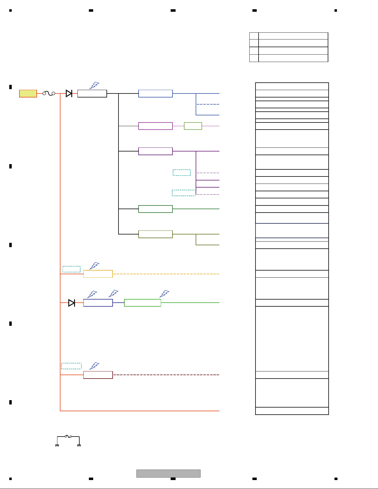
4.2 POWER BLOCK DIAGRAM
ACD
SYSPW
SW5VCNT
VDDCNT
Voltage
Current
Voltage
Current
Voltage
Current
Voltage
Current
Voltage
Current
VDDCONT
SYNC DDON DDON
ILMPW
7.76
5.00
300mA 185mA
Power Amp
3 --> 5 IC
Voltage
USB 5V
LED Reg
Grille low model
50.00 mA PD6586A
5.25 5.50
SWVDD
System u-con
Mecha VDD
TELIN
6.20
460.0 mA
1.30
190.0 mA
2.00 mA
171.00 mA
Grill u-com
System u-con
7.42 7.59
25.00 mA 10.00 mA
TC7SET08FUS1
1.25
60.0 mA
300 mA
Flash ROM
E-Volume(Digital)
1.20
Power Amp (Mute)
Reg 3.3
PM9013A
MX25L1633E
SH7266
SH726a
B.UP
IC REGURATER
Mecha VD 7.4V
S11.6 STD
S11.6 STD171.00 mA
Lithio
SYS+B
1100 mA
Mecha VD
216.00 mA
B.REM A.ANT
25.00 mA
10 mA
3.15 3.30 3.45
150.00 mA
MAX
18.00 mA
6.20
55.00 mA
E-Volume (Analog)
5.60
VDD 3.3V
VDD 1.2V
PART NO .
38.00 mA PM9013A
TYPE
DD-CON USB 5V
Current
140mA
1200 mA
USB 5V
1000 mA
-
5.00
SW 5V
60.00 mA
4.75
Lithio-Tuner
390.0 mA
K/B Illumi (LED)
CD model
CD model
SYNC EN
LED model
TELIN model
10A
(YEK5001-A)
EN
RCA GND Audio GND
P251
CEK1286
3A
A DEH-1700UB/XNEW5
B DEH-1700UBA/XNEW5
C DEH-1700UBB/XNEW5
D DEH-1700UBG/XNEW5
IC911
BA49183-V12
IC451
MM3571A33P
IC552
BD2232G-G
IC551
BD9876EFJ
10
DEH-1700UB/XNEW5
5678
56
7
8
C
D
F
A
B
E
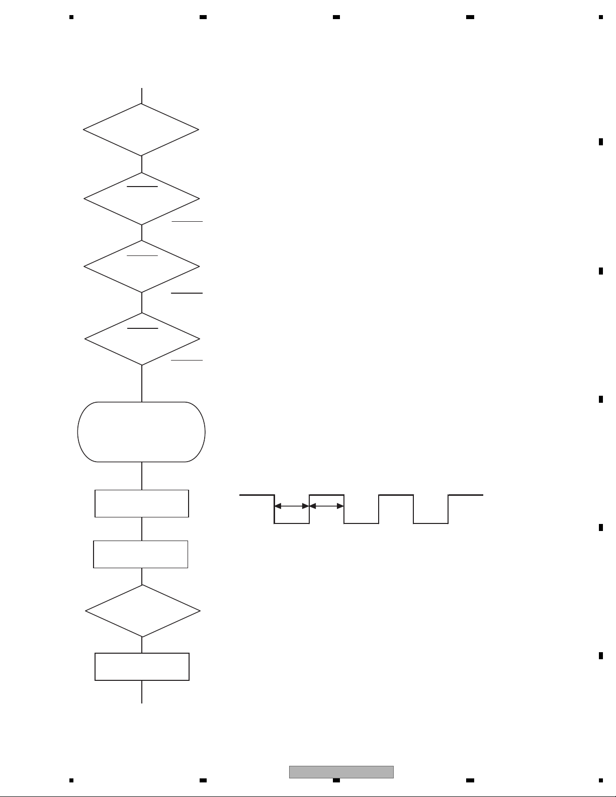
Vcc = 1.2 V
PVcc = 3.3 V
BSENS
Pin 90
ASENS
Pin 89
DSENS
Pin 34
BSENS = L
DSENS = L
Starts
communication
with Grille
microcomputer.
SWVDD <- H
Pin 1
Source keys
operative
Source ON
SYSPW <- H
Pin 8
300 ms
300 ms
In case of the above signal, the communication
with Grille microcomputer may fail.
If the time interval is not 300 msec, the oscillator
may be defective.
Completes power-on operation.
(After that, proceed to each source operation)
Power ON
ASENS = L
Vcc : Pin 12, 20, 43, 78, 86, 109
PVcc : Pin 3, 16, 28, 36, 48, 69, 82,101, 112
5. DIAGNOSIS
5.1 OPERATIONAL FLOWCHART
DEH-1700UB/XNEW5
11
1234
1234
C
D
F
A
B
E
5.2 ERROR CODE LIST
8-digit display 6-digit display 4-digit display
ERROR-xx ERR-xx E-xx
(2) LIST OF CD ERROR CODES (Error Mode: 0xFD)
Code Classification
Error code to be displayed
Details and possible causes
10 Servo Carriage Home NG The pickup cannot move toward the inner track.
The CRG cannot move from the inner track.
--> Defective HOME SW; Failure in CRG movement.
07 Servo TOC reading NG TOC information cannot be read.
--> The partial disk or TOC content is illegal.
11 Servo Focus NG Focusing not available
--> Disc placed upside-down; Stains on the disc; excessive vibration.
17 Servo Setup NG The laser output cannot be adjusted. Focus can be easily lost.
--> Scratches or stains on the disc; excessive vibration.
15 Servo RF NG The digital signal from the disc cannot be detected.
--> A CD-R/RW disc that does not contain data loaded.
12 Servo Spindle Lock NG
Subcode NG
RF-amp NG
Spindle not locked. Subcode not readable.
Proper RF AMP gain not obtained.
--> Defective spindle; Scratches or stains on the disc; excessive vibration.
-->
A CD-R/RW disc that does not contain data loaded, or in a rare case, disc placed upside-down.
--> RF signal error.
30 Servo Search Time Out Failed to reach a target address. And, the search became a timeout.
--> Carriage/Tracking error; Scratches on the disc; Stains on the disc
50 Mechanism Load NG
Eject NG
Disc loading/ejection not completed
--> A foreign object inserted in the mechanism; Disc jammed.
51 Mechanism Failure in retried
turning for ejection
Disc could not be ejected even after disc turning had been retried.
--> A foreign object inserted in the mechanism; Disc jammed.
ERROR CODES
(1) DISPLAY METHOD
If “0xFD” error mode is displayed in CD MODE (CD MODE area for display), an error code will be displayed in the MIN (minute
display) and SEC (second display) areas.
The same code is displayed in the MIN and SEC areas.
The TNO area is blank (#0FFH), as it conventionally was.
• Display example of the head unit
Depending on the display capability of LCDs, the display format varies, as shown below. XX denotes an error number.
Note: In a case of an OEM product, the error display format is subject to the specifications used by the equipment
manufacturer.
If a CD memory device is inoperable, or operation of such media is stopped by an error, the error mode is established and a
cause of the error is displayed by an error code. Indication of error codes is intended to reduce the number of calls from
customers and facilitate failure analysis and repair work in servicing.
• The 2 high-order digits of an error code denote the main classification, shown below.
code classification
0x
1x Servo-related errors
3x
5x Mechanism-related errors
• How to restore from each error is shown below.
Servo-related errors(0X, 1X, 3X) : Servo-related errors CD Off, Eject, ACC Off, Back-up Off, Communication reset, Reset
Load NG/Eject NG(50) : Reload, Eject, ACC Off, Back-up Off, Communication reset, Reset
Failure in retried turning for ejection : CD On, Eject, ACC Off, Back-up Off, Communication reset, Reset
NOTES
• Indications of error codes are available only during disc operations, because CD operations are unavailable if a mechanical error is
generated.
• If the TOC cannot be read, It stops because of error 07.
• If you design a new head unit, be sure to use one of the display formats indicated in “Display example of the head unit.”
12
DEH-1700UB/XNEW5

5678
56
7
8
C
D
F
A
B
E
Common
NO XXXX (NO TITLE, for example)
→ There is no embedded text information.
–Switch the display or play another
track/file.
CD player
ERROR-07, 11, 12, 17, 30
→ The disc is dirty.
– Clean the disc.
→ The disc is scratched.
– Replace the disc.
ERROR-07, 10, 11, 12, 15, 17, 30, A0
→ There is an electrical or mechanical
error.
– Turn the ignition switch OFF and back
to ON, or switch to a different source,
then back to the CD player.
ERROR-15
→ The inserted disc is blank.
– Replace the disc.
ERROR-23
→ Unsupported CD format.
– Replace the disc.
FORMAT READ
→ Sometimes there is a delay between the
start of playback and when you start to
hear any sound.
– Wait until the message disappears and
you hear sound.
NO AUDIO
→ The inserted disc does not contain any
playable files.
– Replace the disc.
SKIPPED
→ The inserted disc contains DRM
protected files.
–The protected files are skipped.
PROTECT
→ All the files on the inserted disc are
embedded with DRM.
– Replace the disc.
USB device
FORMAT READ
→ Sometimes there is a delay between the
start of playback and when you start to
hear any sound.
– Wait until the message disappears and
you hear sound.
NO AUDIO
→ There are no songs.
– Transfer the audio files to the USB
device and connect.
→ The connected USB device has security
enabled.
– Follow the USB device instructions to
disable the security.
SKIPPED
→ The connected USB device contains
DRM protected files.
– The protected files are skipped.
PROTECT
→ All the files on the connected USB
device are embedded with DRM.
– Replace the USB device.
N/A USB
→ The connected USB device is not
supported by this unit.
– Disconnect your device and replace it
with a compatible USB device.
CHECK USB
→ The USB connector or USB cable has
short-circuited.
–Check that the USB connector or USB
cable is not caught in something or
damaged.
→ The connected USB device consumes
more than maximum allowable current.
– Disconnect the USB device and do not
use it. Turn the ignition switch OFF
and back to ACC or ON. Connect only
compliant USB devices.
ERROR-19
→ Communication failed.
–Perform one of the following
operations, then return to the USB
source.
• Turn the ignition switch OFF and
back to ON.
• Disconnect the USB device.
• Change to a different source.
ERROR-23
→ USB device was not formatted properly.
– Format the USB device with FAT12,
FAT16 or FAT32.
STOP
→ There are no songs in the current list.
– Select a list that contains songs.
AMP ERROR
→ This unit fails to operate or the speaker
connection is incorrect; the protection
circuit is activated.
–Check the speaker connection.
–Check the power IC and its peripheral
circuit.
DEH-1700UB/XNEW5
13
1234
1234
C
D
F
A
B
E
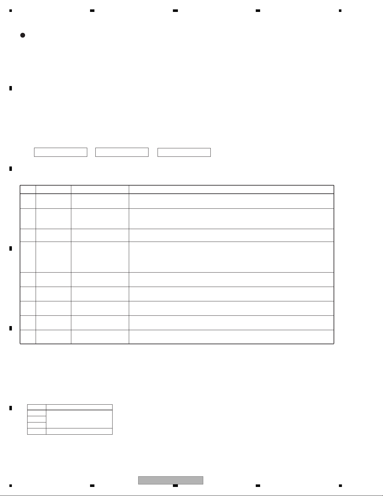
5.3 CONNECTOR FUNCTION DESCRIPTION
FM/AM ANTENNA INPUT
REAR OUTPUT or
SUBWOOFER OUTPUT
1 FL+
2 FR+
3 FL4 FR5 RL+
6 RR+
7 RL8 RR-
9 TEL (Except DEH-1700UBA)
NC (DEH-1700UBA Only)
10 NC
11 NC
12 NC
13 ACC
14 B.REM
15 B.UP
16 GND
16
14
12
10 8
6
42
15
13
11
97
5
31
WIRED
REMOTE
CONTROL
(Except DEH-1700UBA)
14
DEH-1700UB/XNEW5
5678
56
7
8
C
D
F
A
B
E
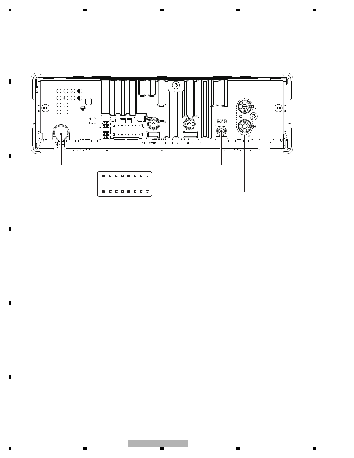
Grille condition
Conf. item Operate Show LCD ILM
All light up
EQ + LIST
Draw 1 ILM(1)
All light off SOURCE No light Draw2 No light
Conf. LCD pattern 1
(* And change ILM color)
BAND Draw 3
ILM(2)
(If not have, ILM(1) light on)
Conf. LCD pattern 2
BACK
Draw 4 ILM(1)
Drawings Style
Draw1 ALL light up
Draw2 ALL light off
Draw3
Draw4
BAND BACK
SOURCE
LIST
Press and hold "EQ" and "LIST" buttons together, and turn BUP and ACC on.
[How to enter Test mode]
EQ
6. SERVICE MODE
6.1 DISPLAY TEST MODE 1
DEH-1700UB/XNEW5
15
1234
1234
C
D
F
A
B
E
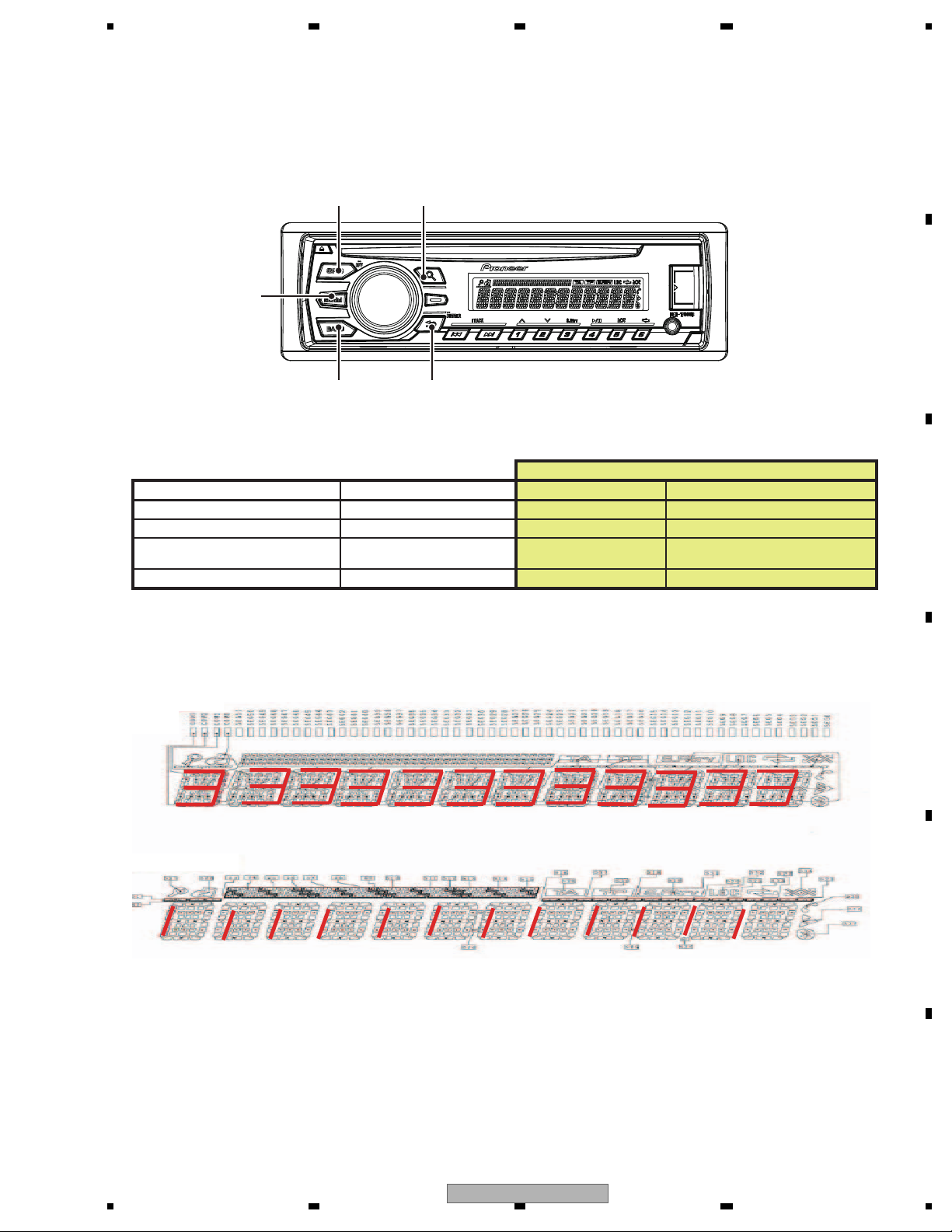
6.2 DISPLAY TEST MODE 2
* Initial
condition
$ PD number
For Ver.7.01, "701" is displayed
For PEA010A, "010A" is displayed
# System
microcomputer
version
S
$$$$
###
1 + 3
On (state when
entering test mode)
Press and hold "1" and "3" buttons together, and turn BUP and ACC on.
[Operation key]
[How to enter Test mode]
[Test items]
Start display test mode.
Press and hold "1" and "3" buttons together, and turn
BUP and ACC on.
Display is normally updated
Display update is stopped
Product operation is performed as usual, in appearance.
The screen gets still when entering this item.
On (an initial value)
On (lighting condition
of normal times)
On (an initial value or
setting value of default
menu)
On (an initial value or
setting value of default
menu)
On (an initial value or
setting value of default
menu)
Off
All off
All off
All off
Remarks
Key Illumination
Operation key Processing
Icon
Enter display test mode
Switch to next test mode
The information such as the system microcomputer version is checked.
Switching to next display
by pressing “ 1 ” + “ 3 ” buttons together.
Switching to next display
by pressing “ 1 ” + “ 3 ” buttons together.
Switching to next display
by pressing “ 1 ” + “ 3 ” buttons together.
System Version information is displayed.
16
DEH-1700UB/XNEW5
5678
56
7
8
C
D
F
A
B
E
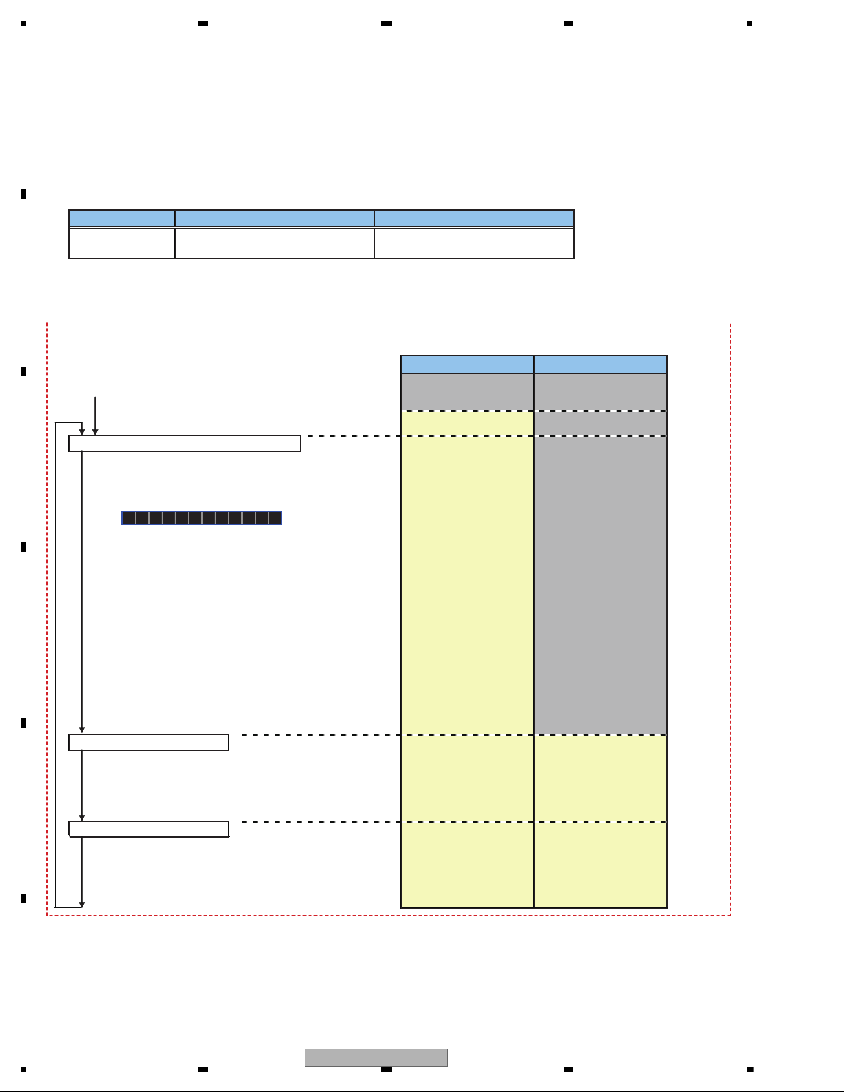
Overview
This mode is used for upgrading the MCU software of system using USB memory.
How to enter in USB rewriting mode
Press and hold "1" and "2" buttons together, and turn BUP and ACC on.
USB rewriting operation flow
Explanatory note
Screen display and ON/OFF of illumination
Characters displayed on the screen
Red frame: illumination lights up
Gray frame: illumination lights off
Blue characters: operation to be carried out by a user of USB rewriting function
Press and hold "1" and "2" buttons together, and turn BUP and ACC on.
Press LIST button
* After connecting USB memory in which upgrading file is stored, press LIST button.
(4) Retry count over
Retry rewriting
Check of upgrading file is started
(2) Upgrading file is not detected
Upgrading file error
After retryFirst time
Rewriting is started
Switched every
5 seconds
(3) Rewriting failed
(1) Rewriting succeeded
Result of rewriting
(1) Rewriting succeeded
(2) Upgrading file error
Upgrading file is not detected
(3) Rewriting failed
(4) Retry count over
FILE ERROR
DON'T STOP
PRG **/100
ERR->RETRYCAN'T UPDT
USB
START UPDT
CHECK FILE
In 5 seconds, usual operation
(OFF SOURCE)
As the reset is internally carried out,
display and illumination go out
In 5 seconds, usual operation
(OFF SOURCE)
In 5 seconds, rewriting
is retried
In 5 seconds, rewriting
is retried
Display is continued until
the power supply is turned
OFF
If the power supply is turned OFF
during rewriting, retry the rewriting.
Displayed when there is no upgrading file in USB memory or the data of upgrading file is different.
In 5 seconds, usual operation (OFF SOURCE) is started.
If the upgrading file error is detected or the upgrading file is not detected after the rewriting is retried, the rewriting is failed.
In 5 seconds, rewriting is retried.
Displayed when the retry becomes unavailable because the retry count is exceeded.
The display is continued until the power supply is turned OFF. If the power supply is turned ON again, the display is not changed.
The upgrading using USB is disabled, so it is necessary to write programs in serial Flash using E10A.
Displayed when the writing of upgrading file in serial Flash is not normally terminated.
Or, displayed if the upgrading file error is detected or the upgrading file is not detected after the rewriting is retried.
In 5 seconds, rewriting is retried.
Displayed when USB rewriting is normally terminated.
In 5 seconds, usual operation (OFF SOURCE) is started.
ERR->RETRY
COMPLETE
6.3 SOFTWARE VERSION UP METHOD
DEH-1700UB/XNEW5
17
1234
1234
C
D
F
A
B
E
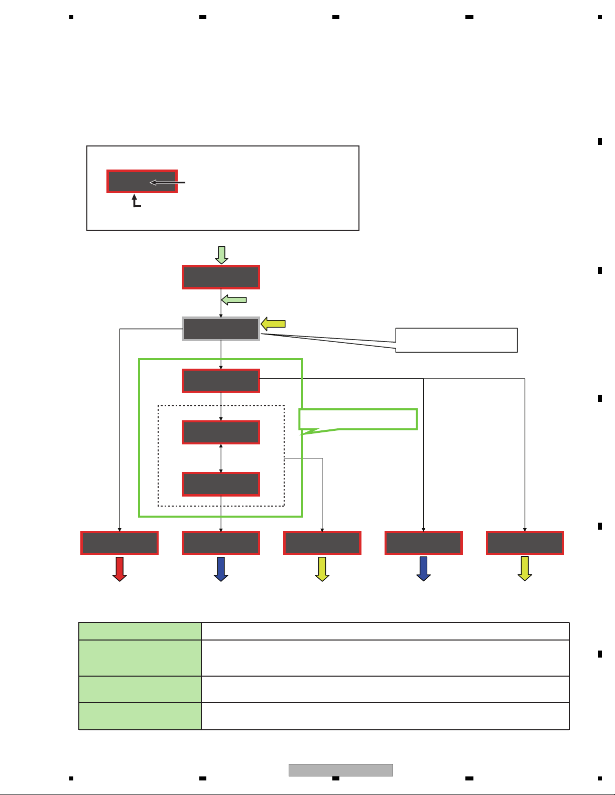
6.4 CD TEST MODE
- Flow Chart
To enter the test mode: [4] + [6] -> BUP + ACC ON
[CD] or [SOURCE]
Source ON
TRK MIN
[BAND]
Power On
(T.Offset is adjusted)
TRK MIN SEC
00 00 00
[Key]
Contents
Display
[2]
TRK MIN SEC
GG GG GG
RF AMP
Gain switching
*1
[BAND]
Power Off
TRK MIN SEC
[BAND]
Power Off
TRK MIN SEC
[BAND]
Power Off
TRK MIN SEC
[BAND]
Power Off
TRK MIN SEC
[3]
Focus Close
S curve check
TRK MIN SEC
91 91 91
[1]
T.Close & AGC
Applicable servomechanism
TRK MIN SEC
?tr ?min ?sec
[1]
F,T,RF AGC
F.Bias display switching
TRK MIN SEC
[6]
Focus Mode switching
TRK MIN SEC
[3] [>]
*5
TRK MIN SEC
?tr ?min ?sec
0X 0X 0X
F,T AGC / F.Bias
RF AGC
*2
RF AGC coefficient display
[1]
Tracking Servo
Close
00 00 00
or 99 99 99
[3]
RF AGC /
TRK MIN SEC
?? ?? ??
[>]
CRG +
00 00 00
or 99 99 99
[>]
CRG +
8X 8X 8X
or 9X 9X 9X
CRG/TR Jump +
TRK MIN SEC
?tr ?min ?sec
[<]
CRG -
00 00 00
or 99 99 99
[<]
CRG -
8X 8X 8X
or 9X 9X 9X
[<]
*4 *4
CRG/TR Jump -
TRK MIN SEC
?tr ?min ?sec?? ?? ??
[2]
Tracking Open
8X 8X 8X
or 9X 9X 9X
*6
[2]
Self-adjusting
switching
TRK MIN SEC
[2]
T.Balance adjustment /
T.BAL coefficient display
TRK MIN SEC
[2]
or 9X 9X 9X
*3*6
?? ?? ??
?? ?? ??
Tracking Open
8X 8X 8X
*1) TYP t + 6 dB t + 12 dB
TRK
MIN
SEC
TRK06MIN06SEC
06
TRK12MIN12SEC
12
*2) Focus Close
TRK00MIN00SEC
TRK99MIN99SEC
(
t S. Curve t F EQ measurement setting
00
TRK
MIN01SEC
01
01
TRK02MIN02SEC
99)
02
[Key]
[BAND]
[>]
[<]
[1]
Power On/Off
CRG + / TR Jump +
(Direction of the external surface)
CRG - / TR Jump (Direction of the internal surface)
T. CLS & AGC & Applicable servomechanism /
Test Mode
AGC,AGC display setting
Operation
[2]
*3) F.Offset Display t
RF.Offset
t
T.Offset Display t
Switch to the order
of the original
display
*4) 100TR Jump
*5) TRK/MIN/SEC
t F.AGC t T.AGC Gain t F.Bias t RF AGC
RF Gain switching / Offset adjustment display /
T.Balance adjustment / T. Open
[3]
F. Close,S. Curve / Rough Servo and RF AGC /
F,T,RF AGC
[6]
F. Mode switching / Tracking Close
*6) CRG motor voltage = 2 [V]
After the [EJECT] key is pressed keys other than the [EJECT] key should not be pressed, until disc ejection is complete.
When the key [2] or [3] is pressed during the Focus Search, the power supply should be immediately turned off (otherwise the lens sticks
to Wall, causing the actuator to be damaged).
In the case of 100TR Jump, the mechanism shall be set to the Tracking Close mode when the key is released.
When the power is turned on/off the gain of the RFAMP is reset to 0 dB. At the same time all the self-adjusting values shall return to the
default setting.
Do not do Tracking Servo Close before doing Focus Servo Close. (Because the overcurrent flows)
18
DEH-1700UB/XNEW5
 Loading...