

Page 1
PIONEER CORPORATION 4-1, Meguro 1-chome, Meguro-ku, Tokyo 153-8654, Japan
PIONEER ELECTRONICS (USA) INC. P.O. Box 1760, Long Beach, CA 90801-1760, U.S.A.
PIONEER EUROPE NV Haven 1087, Keetberglaan 1, 9120 Melsele, Belgium
PIONEER ELECTRONICS ASIACENTRE PTE. LTD. 253 Alexandra Road, #04-01, Singapore 159936
PIONEER CORPORATION 2005
ORDER NO.
CRT3495
DVD MECHANISM MODULE(MG4)
CX-3150
--
--
This service manual describes the operation of the DVD mechanism module incorporated in models
listed in the table below.
--
--
When performing repairs use this manual together with the specific manual for model under repair.
Model Service Manual DVD Mechanism Module
FX-MG9857DVZT/UC
FX-MG9857DVZT-91/UC
FX-MG9857DVZT/EW
FX-MG9857DVZT-91/EW
FX-MG9757DVZT/EW
FX-MG9757DVZT-91/EW
FX-MG9757DVZT/AU
FX-MG9757DVZT-91/AU
CRT3494 CXK7402
CONTENTS
1. CIRCUIT DESCRIPTIONS . . . . . . . . . . . . . . . . . . . . . . . 2
2. MECHANISM OVER VIEW . . . . . . . . . . . . . . . . . . . . . . 19
3. DISASSEMBLY . . . . . . . . . . . . . . . . . . . . . . . . . . . . . . . 29
4. HOW TO ASSEMBLE . . . . . . . . . . . . . . . . . . . . . . . . . . 37
K-ZZU. JULY 2005 Printed in Japan
Page 2
1234
1. CIRCUIT DESCRIPTIONS
A
B
MN35103UB and MN35104UB are 1-chip LSI for DVD-Player. The connection of this LSI to the Driver IC,
SDRAM, Flash-ROM, Audio-DAC, etc. can configure the DVD-Player System.
This LSI contains Front End (SODC/FE) that performs RF signal /Servo /Decode processings, Back End
(AV decoder/BE) that performs the video decode processing such as MPEG1/MPEG2/JPEG and audio decode
processing such as DVD-Audio/AC-3/DTS/MP3, and the system controller (Siscon) for controlling the system.
Front End part realizes the arithmetic processing of optical head signal and RF signal processing,
the digital signal processing for DVD-ROM reproduction that conforms to DVD standards (16-8 Demodulation,
Error correction), the digital signal processing for CD-DA/CD-ROM (Error correction), AV decoder transmission,
servo control, spindle motor control and seek control.
Please take note that, since (FEP) and (SODC) with DVD mecha-module (MS3) of CX-3016 are integrated into
one chip at MN35103UB and MN35104UB, the waveforms of servo system on the front end which had
previously appeared at MS3, i.e., the waveforms of FE, TE and AS, cannot be seen anymore.
1.1 Analog Block (MN35103UB, MN35104UB:IC1501)
1 Front End Part (MN35103UB, MN35104UB:IC1501)
The analog block for IC1501 generates the servo signals including focus and tracking, processes addition of
RF signals, and controls the laser power of pickup.
The servo system contains focus operation amp, focus offset adjustment circuit, 3-beam tracking operation amp,
phase difference tracking detection circuit, tracking offset adjustment circuit, TE2 value-making circuit.
Also, RF signal processing system contains the functions of AGC and equalizer.
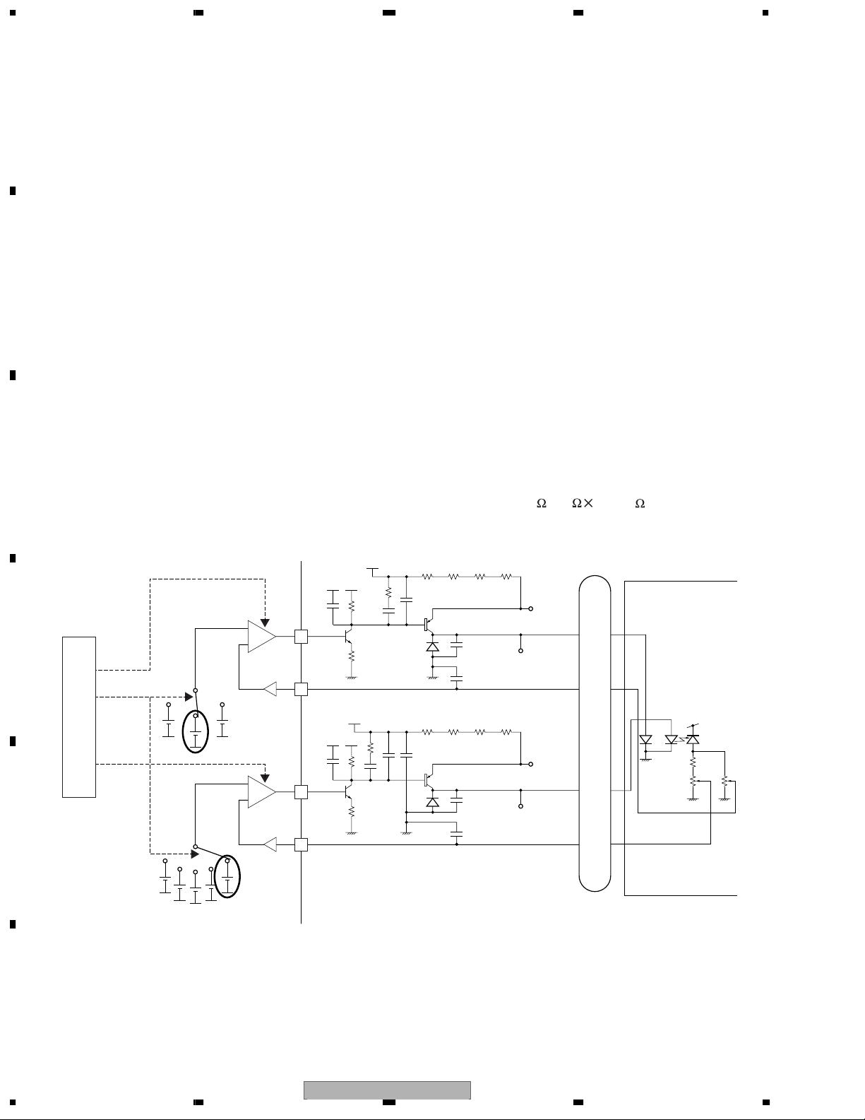
1.1.1 APC Circuit
The optical output for the laser diode (LD) has large minus temperature characteristics. Therefore, the constant
C
optical output cannot be obtained when LD is driven by the constant current. APC circuit controls the electric
current so as to provide constant output at the monitor diode (MD). MN35103UB and MN35104UB contain two
types of APC circuits, one for DVD and another for CD. The LD electric current for DVD (CD) can be obtained by
dividing the voltage measurements between DVDLD1 (CDLD1) and 5V by 15.6 (3.9 4=15.6 ). For DVD (CD),
the results are approx. 26mA (44mA).
+5V
+
+
–
D
LDONCD
LDPOWER
Reg.
LDONDVD
0.17V
–
0.25V0.18V
+
+
–
–
LPCO2
LPC2
+5V
+
LPCO1
E
LPC1
0.59V 0.18V
0.5V
0.25V
0.22V
3.9Ω 3.9Ω 3.9Ω 3.9Ω
+
3.9Ω 3.9Ω 3.9Ω 3.9Ω
+
CDLD1
CDLD0
DVDLD1
DVDLD0
CN1101
24
5
26
7
78LD
78MD
65LD
65MD
CDLDDVD
LD
PU unit
+5V
MD
F
CX-31502
1234
Page 3
5 678
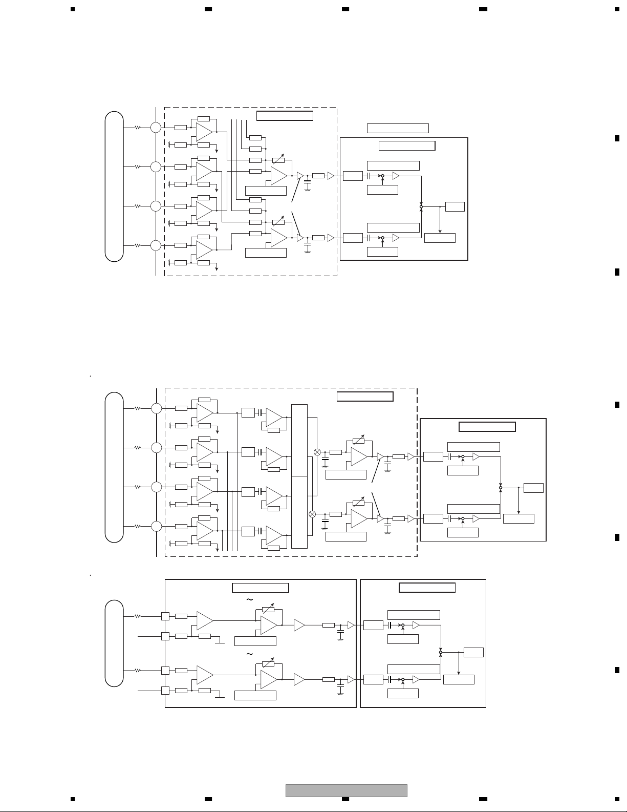
1.1.2 FE Generation Circuit
Focus Error (FE) Generation Circuit
Each of input signals from B1 to B4 which had been quartered by PU within the analog block is input to IC 1501
passing through the resistance and becomes a signal of FE
offset adjustment value. Then, the signal is AD-converted within the servo block and adds an offset cancel value
to become FE, generating a signal of FE=(FE+)
CN1101
VIN5
B1
B2
B3
B4
16
91
VIN6
15
92
VIN7
13
93
VIN8
11
94
–
+
–
+
OFFSET ADJ
–
+
–
+
OFFSET ADJ
-
(FE-).
Analog block
–
+
x1 or x4
–
+
+=
-
(B1+B3) and FE
1+(Pfbal/0x10000)
1+(Pfbal/0x10000)
+
FE
FE
Pfepofs
1-(Pfbal/0x10000)
-
Pfenofs
+
+
Servo block
-=-
(B2+B4) after adding a focus
FE
–
Dfesv
A
B
1.1.3 TE Generation Circuit
Trackings Error (TE) Generation Circuit
For DVD, TE is generated, with the application of a phase contrast method, from the phase difference of (B2+B4)
and (B1+B3). For CD, TE is generated, with the application of a 3-beam method, by sending the signal to the
variable amp set for the tracking offset adjustment via outer-attached resistance and then by AD-converting it to
–
+
–
+
–
+
–
+
–
+
–
+
-
C.
VHALF
VHALF
+
EQ
–
+
EQ
–
+
EQ
–
+
EQ
–
Analog block
-
6dB 15dB(3dB STEP)
0dB/12dB
–
+
OFFSET DAC
-
6dB 15dB(3dB STEP)
0dB/12dB
–
+
OFFSET DAC
PC
PC
G
G
Analog block
OFFSET ADJ
OFFSET ADJ
30kHz
30kHz
–
+
x1 or x4
–
+
1+(Pfbal/0x10000)
+
TE
-
TE
TE
TE
Servo block
+
Pfepofs
1-(Pfbal/0x10000)
+
Pfenofs
1+(Pfbal/0x10000)
+
+
Pfepofs
1-(Pfbal/0x10000)
+
Pfenofs
–
Dfesv
Servo block
TE
–
TE
Dfesv
make the formula of TE=A
DVD (TE from phase difference)
CN1101
VIN1
16
B1
B2
B3
B4
95
VIN2
15
96
VIN3
13
97
VIN4
11
98
CD (3-beam TE)
CN1101
17
A
VIN9
20kΩ
VREFH
10
C
VIN10
VREFH
20kΩ
C
D
E
56
CX-3150
F
7
8
3
Page 4
1234
1.2 Servo Block (MN35103UB, MN35104UB:IC1501)
Servo block performs focus, tracking, servo control for traverse, spindle motor control and seek control.
A
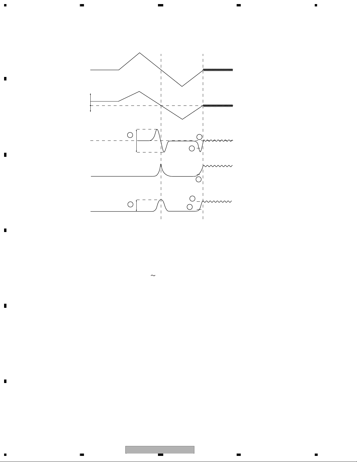
1.2.1 Focus Close
FODRV
Far from disc
Lens
B
C
Close to disc
FE
RFENV
AS
1
2
5
4
7
6
3
VHALF
Focal point
After issuing the focus close command, the following processes are taken for both DVD and CD.
1. Measure and optimize signal levels
First drive PU lens far from the disc and then drive closer to the disc. At the focal point met in the process of
this move, measure signal levels of FE, AS and RFENV respectively, and optimize their levels for FE and AS
(1 & 2 in the above figure).
2. Focus closing
D
Next, drive the lens far from the disc again to detect the closing levels of FE and AS.
Then activate focus loop filter for closing focus (3 6).
3. Check closing
Check the closing with signal levels of AS and RFENV (6 & 7).
Focus search in test mode can check the signal levels and focus drive voltages for FE, AS and RFEV.
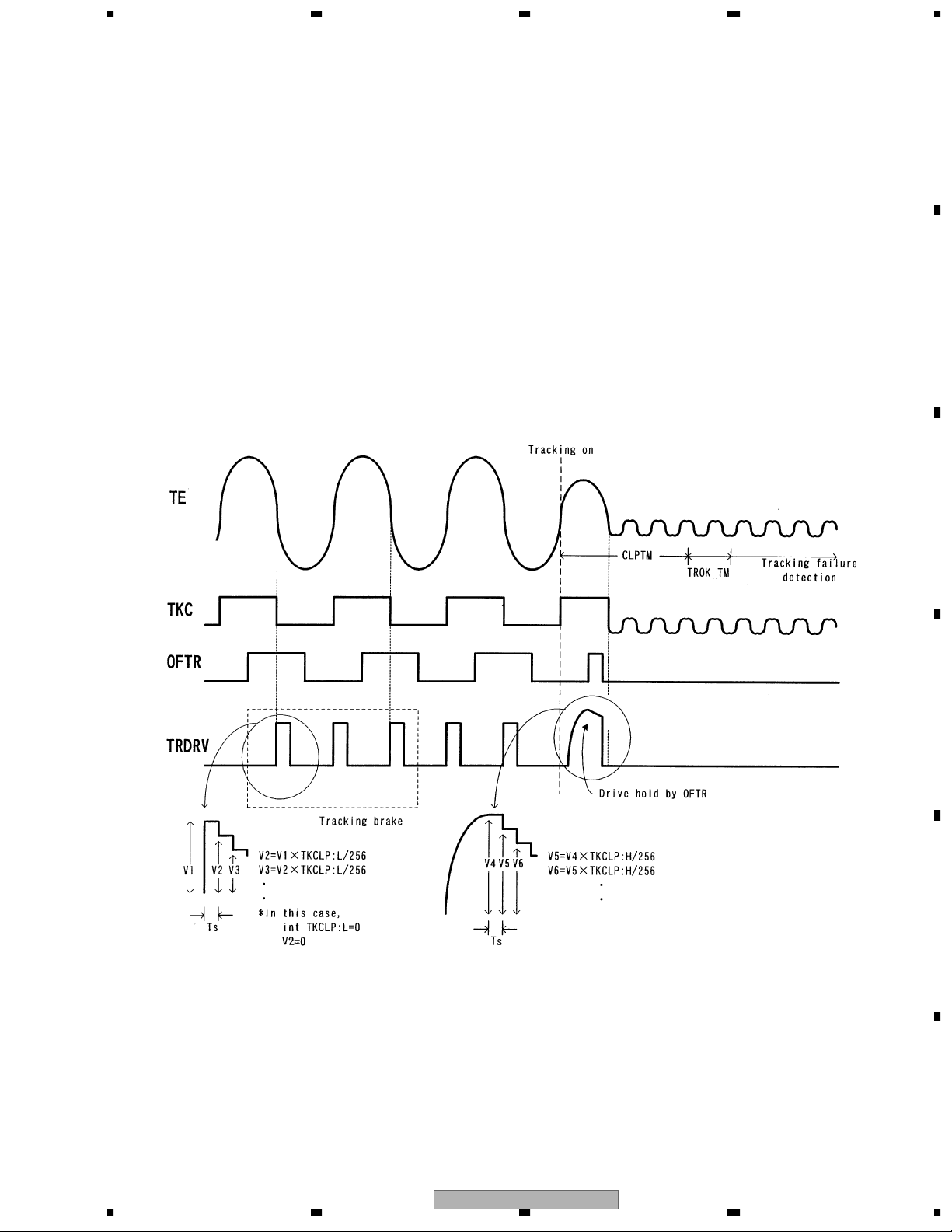
1.2.2 Tracking Close
After issuing the tracking close command, the following processes are taken for both DVD and CD.
1. Tracking brake
Measure one half cycle of the tracking cross and if the cycle is within the range of designation, output the brake
E
F
pals.
Output direction of brake pals is determined by the phase relations of OFTR and TKC (TE's binarization) signals.
After confirming that the swing of lens against disc is controlled, the brake stops and the closing begins. If the
closing condition is not met within 10msec. after outputting brake, the brake stops and the closing begins.
2. Tracking closing
Process the tracking drive hold with OFTR signal.
3. Check closing
Check whether or not the track jump does not exceed the designated number within the designated term.
Closing check will be time-out at 20msec. Retry using a command from the microcomputer.
1234
CX-31504
Page 5
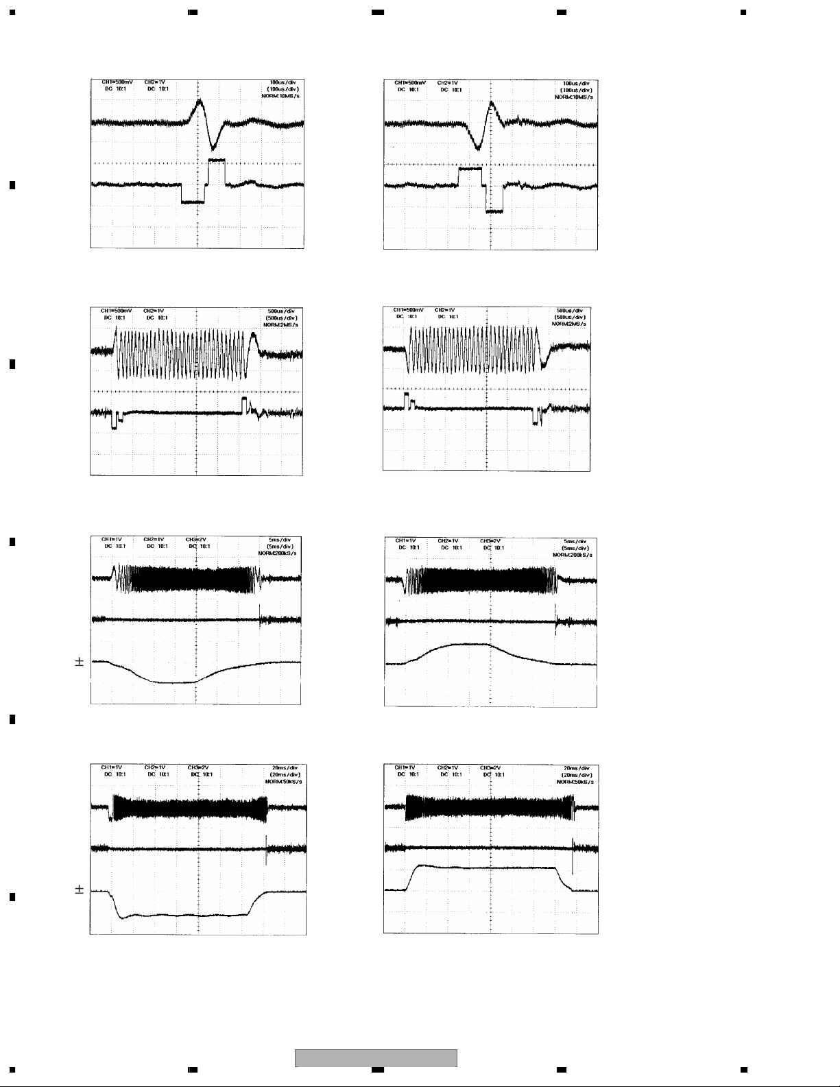
1.2.3 Track Jump
The system selects from three types of methods; i.e. interval jump, multi jump and traverse seek,
according to the target number of moving tracks.
1. Interval Jump
The detailed seek is capable due to the execution of repetitive one-track jumps.
It is used when approaching to the target track or seek-operating to an adjacent track.
2. Multi Jump
It counts both edges of the track cross signal TKC and moves for designated number of track counts.
3. Traverse Seek
It controls the movement speed by measuring the time of the track cross signal TKC and manages the
vibration of pickup generated upon movement to the minimum.
Types of target number of moving jumps illustrating the jump switch setting for both DVD and CD.
DVD
1-10 Interval Jump
11-100 Multi Jump
101-500 Combination of Multi Jump and Interval Jump
Over 501 Traverse Seek
The waveforms of track jumps are shown in the next page.
CD
1-10 Interval Jump
11-32 Multi Jump
33-500 Combination of Multi Jump and Interval Jump
Over 501 Traverse Seek
5 678
A
B
C
D
56
CX-3150
E
F
7
8
5
Page 6
1234
Interval Jump (1 Track)
Outer Jump Inner Jump
A
TE
TD
B
Multi Jump (32 Track)
Outer Jump Inner Jump
TE
TD
C
Traverse Seek (501 Track)
Outer Jump Inner Jump
TE
TD
D
CO
Traverse Seek (5000 Track)
Outer Jump Inner Jump
E
TE
TD
CO
F
CX-31506
1234
Page 7
(1 Layer)
(0 Layer)
object lens
L1
L0
L1
L0 L1
L0
L1 L0
A D
B C
A
D
B
C
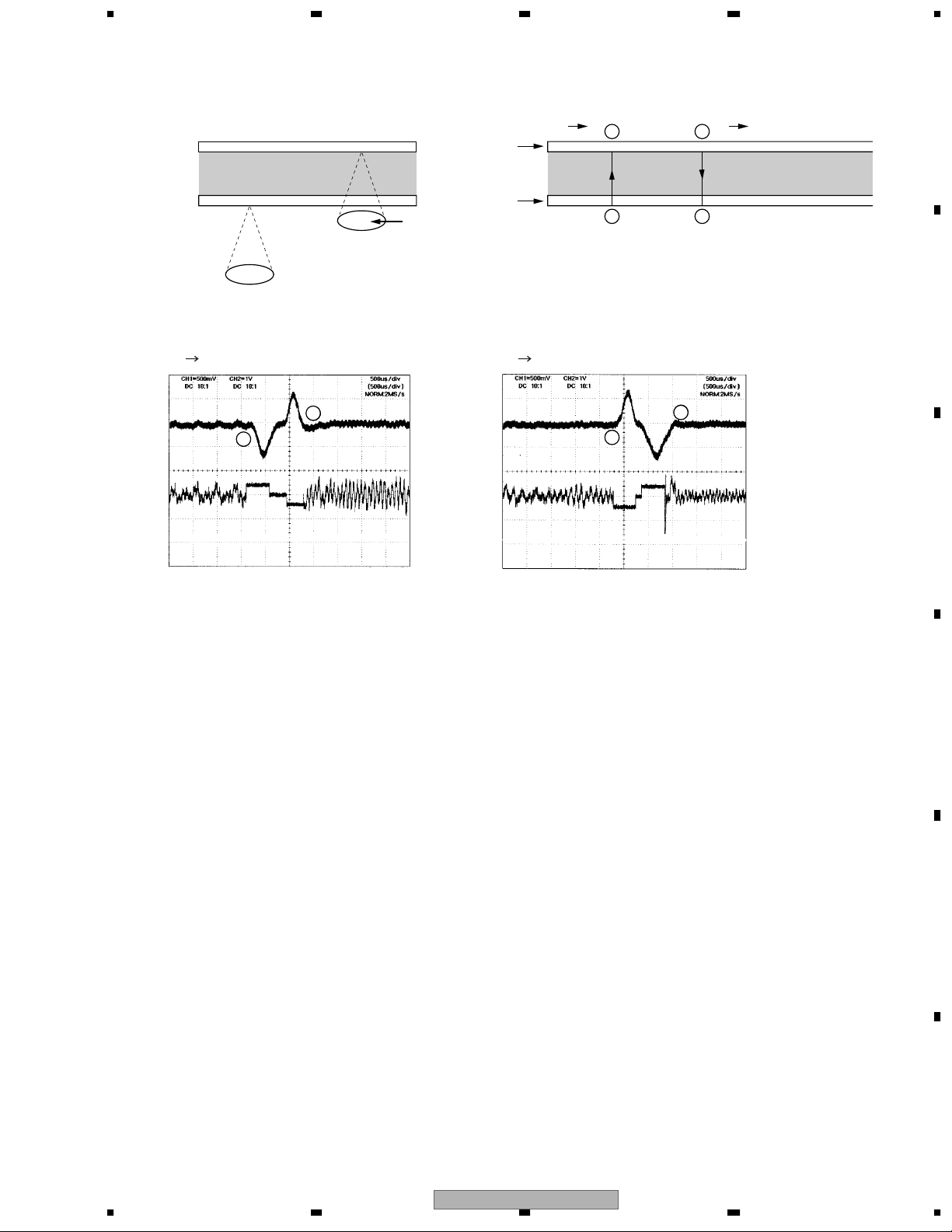
1.2.4 Focus Jump
Focus jump is a function corresponding to the single-sided or both-sided two-layers.
Seen from the object lens, a forward layer is called 0 Layer (L0) and a farther one is called 1 Layer (L1).
The flow of focus jump is shown below.
1. Open tracking at the layer during play.
2. Issue a command to execute jump to the target layer.
3. At the jumped layer, replay by closing the tracking.
Also, the processes when issuing a jump command are as follows.
1. Accelerate the lens to the target layer until FE signal detects the acceleration completion level for focus jump.
However, if the time of acceleration time-out reaches before detecting the acceleration completion level,
the acceleration will compulsively stop.
2. Move lens with inertia instead of outputting the drive voltage until FE signal detects the deceleration initiation
level.
3. Decelerate lens for the duration from detection of the deceleration initiation level to the deceleration
completion level.
However, if the time of deceleration time-out reaches before detecting the deceleration completion level,
the deceleration will compulsively stop.
The waveforms of focus jump are shown below.
The waveforms of focus jump
FE
FD
L0 L1
L1 L0
5 678
A
B
C
D
E
F
56
CX-3150
7
8
7
Page 8

1234
1.3 Automatic Adjustment Function
This system totally automates the circuit adjustments.
A
The details of automatic adjustments are explained respectively as follows:
1.3.1 FE, TE, AS and Offset Cancel
Each of analog signals for FE, TE and AS generated at FEP is converted into a digital signal by A/D converter
inside servo block. Offset cancel is a function to cancel the input offset of A/D converter when the power is on.
1.3.2 VCO Gain Adjustment (VARI Adjustment)
It has a function to absorb dispersion of VCO gains among LSI solid by learning and to automatically adjust
VCO gains for the constant allocation. Lock VCO to 186- multiplied frequency against the input clock of crystal
criteria, read Frequency Control Value (FCNT), and then adjust VARI register so that the value becomes
equivalent to the target FCNT value.
B
1.3.3 FE Normalization Adjustment
After A/D-converting FE signal level at servo block which was measured at focus close, adjust it to 190LSB at
the digital equalizer input stage.
1.3.4 Spindle Gain Learning
Measure the duration from the halting state of spindle motor to the point reaching the fixed rotation speed for
Gain adjustment. Then adjust in the way of absorbing torque dispersion on spindle motor.
1.3.5 Tracking Balance (TBAL) Adjustment
By applying Newton-Raphson method, search for a balanced point at which DC offset becomes 0 by vibrating
C
lens toward track direction at the time of the focus close and the tracking open.
1.3.6 Tracking Error Amplitude Learning
After vibrating lens toward track direction at the time of the focus close and the tracking open to A/D-convert
the amplitude level to ADSC, adjust it to 190LSB at the digital equalizer input stage.
1.3.7 Focus Balance (FBAL) Adjustment
Adjust the focus position so that RFENV becomes maximum at the tracking close.
1.3.8 Focus Gain Adjustment and Tracking Gain Adjustment
D
Insert disturbance to servo loop at the tracking close and adjust to a target gain intersection.
1.3.9 AS Normalization Adjustment
After measuring AS signal levels for the designated number of samplings at the tracking close to A/D-convert
by ADSC, the precise adjustment is made to set 64LSB at the digital equalizer input stage.
E
F
1234
CX-31508
Page 9
5 678
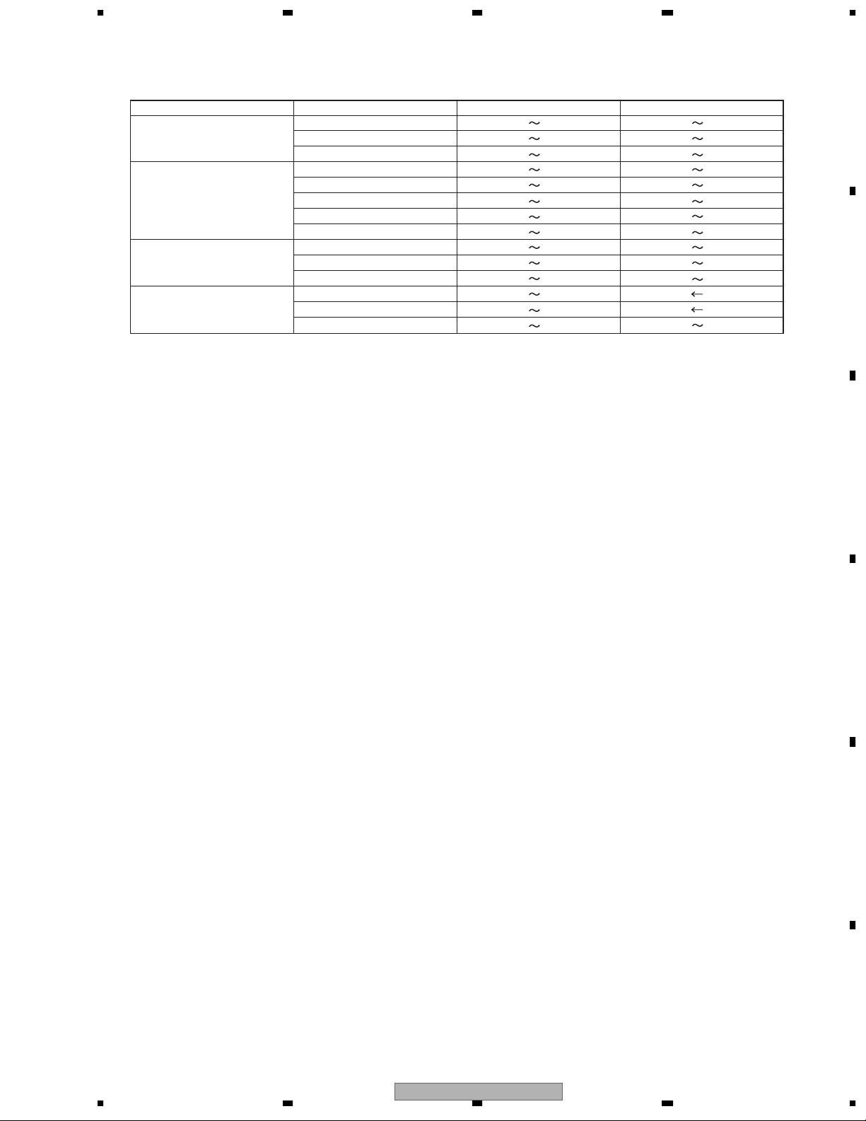
All automatic adjustments can be confirmed by indicating their results at test mode.
List of Automatic Adjustment Coefficients
States
Power On
F Close
F Close (after TBAL)
T Close
Coefficients
FE Offset
TE Offset
AS Offset
Spindle Gain
FE MAX
FE MIN
AS MAX
FE Normalization
TE MAX
TE MIN
TE Normalization
F Gain
T Gain
AS Normalization
FBF0 0410
E8BA 1746
F96D 0693
0121 02E3
1D8B 547E
BADE E7D3
10CB 3753
0125 02FE
1A7C 5ABC
A544 E584
010C 0396
0100 0400
0100 0400
0128 03D0
DVD
FB5C 04A4
F740 08C0
F6B7 0949
0113 0447
1D5A 5663
A99D E2A6
12E2 45E4
0119 033D
0DB5 33D6
CC2A F24B
01D5 06F0
00EA 0364
Note: Coefficients are indicated in hexadecimal numbers.
All figures describe specifications at the production line.
Disc applies DVD
-
REF-A1 for DVD and TCD-782 for CD.
CD
A
B
1.4 CIRC Block (MN35103UB, MN35104UB:IC1501)
CIRC block contains digital signal processing function for CD-DA and CD-ROM (EFM demodulation and error
correction), digital servo processing for spindle motor and 1-bit DA converter with digital filter (Differential OP
amp output with secondary lowpass filter).
1.5 DRC Block (MN35103UB, MN35104UB:IC1501)
Digital Read Channel (DRC) provides A/D converter, adaptive equalization, bit-a-bit detector, digital PLL circuit,
CPU interface and peripheral circuits for reading signals of optical disks.
C
D
E
56
CX-3150
F
7
8
9
Page 10

1234
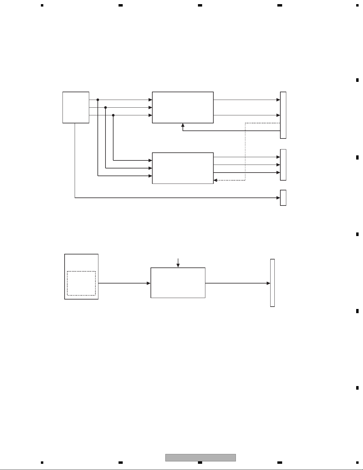
2 Back End Part
2.1 States of Power Supply
A
B
C
VD8V
VD8V
VD5PU
BVC33
SRVDD33
VD5
F.E. Driver System
DISC Detection LED
IC1001
AVCC, for 5V
REG IC
IC1002
VCC, for 5V
REG IC
IC2001
Changer CPU Power Supply
IC1651
SRAM Power Supply
IC1901
VCC33, for 3.3V
REG IC
AVCC5(= 5.0V)
VCC5(= 5.0V)
VCC33(= 3.3V)
IC1851
DAC
Q1551
Peripherals
F.E. System
IC 1201
P.U Peripherals
IC 1501
AV CHIP etc.
VD5
2.2 States of Clock
D
E
Using 27MHz primary crystal (X1801), 27MHz buffer-out (VCLK & BECLK) audio clock (EXTCK & DACCLK
[with 24M/33M/36M switches]) and F.E. part clock (MCK33) are produced with IC1801.
27MHz
Crystal
IC1003
1.5V output
DCDC converter
IC1801
Clock Generator
VCC15(= 1.5V)
States of Power Supply
BECLK
SO1 [24M]
AO1 [33M/36M]
EXTCK
MCK33
IC 1501
AV CHIP
IC1501
AVLSI 170Pin
IC 1802 selector
IC1501
AVLSI 172Pin
IC1501 92Pin
F.E. Part Clock
DACCLK
IC1851
AUDIO DAC
VCC33
States of Clock
F
1234
CX-315010
Page 11
5 678
2.3 Audio Circuit
The serial three lines of audio output from AVLSI is input to IC 1851 (Audio DAC) and the signal that had
become analog audio is output from HOST I/F. For mute circuit, only AMUTE can be output at present,
and Mute Tr is located at the product side.
Asfor6choutput,twokinds,2chrippingoutputtype,and6ch/2chrippingoutputcombinationtype,existbythe
model.Itisdecidedbyproducttypeandspecification.
IEC958(Audiodigitaloutput)haswhatisequippedbythemodel,andthethingwhichisnotequipped.
CN1901
HOST I/F
A
SRCK
IC1503
AVLSI
ADOUT0
LRCK
IC1851
Audio DAC
6ch-Multi channels are now unused.
IC1881 Buffer SW
Ripping or
6ch digtal out
Audio Circuit
2.4 Video Circuit
Composite Video Signal is output from DAC circuit part in AVLSI.
Output from HOST I/F via Buffer circuit.
IC1501
AVLSI
Video DAC
circuit part
COMP
AVCC5
Q1551 peripheral
Video buffer circuit
MCKENA
LD
RO
MCKENA
GNDAU
COMPO
B
CN1881
CN1551
C
CN1901
HOST I/F
D
Video circuit
CX-3150
56
E
F
7
8
11
Page 12
1234
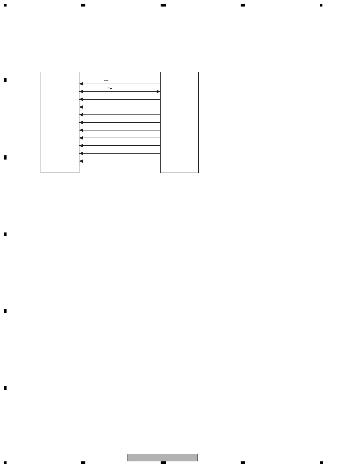
2.5 SDRAM I/F
A
Communication I/F between AVLSI and memory to allocate MPEG stream data as a buffer.
Capacity of SDRAM is 128Mbit.
Note that XCSM, XWE, XCAS, XRAS, XCSM for IC1570 are renamed respectively to NCSM, NWE, NCAS, NRAS,
NCSM for IC1501.
MA0 11
MDQ0 31
MCK
XWE (NWE)
XCAS (NCAS)
B
IC1570
SDRAM
XRAS (NRAS)
XCSM (NCSM)
IC1501
AVLSI
DQM0
DQM1
DQM2
DQM3
SDRAM I/F
C
D
E
F
1234
CX-315012
Page 13
5 678
3 MECHANISM CONTROL
- Overview
The combination of load/eject operation, camgear motor
(operation mode) operation, elevation operation and
clamp operation enables the operation as changer
mechanism module.
3.1 Loading system
Disc position is detected with 3 switches attached to mechanism unit, photo,
and LED, and load/eject is performed by driving an E/L motor. *E/L is
abbreviation of Elevation/Loading. (MG4 mechanism shares a motor like G3
mechanism, unlike G2 or MG3 mechanism.)
A
3.1.1 Detect system
The 3 switches, photo and LED operate load start/load end, disc form detection
and watching disc eject.
3.1.2 Drive system
Controlling an E/L motor by the control unit enables the following function:
Loading of disc
Ejecting of disc
a) Drive system
It controls drive direction by output E/LFWD, E/LREV from
the microcomputer (IC2001), and 3 values of drive voltage
by Hi-Z/H/L of E/LVOL2.
LOADPHT
LOADSWR
LOADSWL
IN/SW
IC2001
98
58
57
87
E/LVOL1
(no use)
MECHANISM
CONTROLLER
730
At the time of loading E/L+<E/L- ; (E/LFWD; L, E/LREV; H)
At the time of ejecting E/L+>E/L- ; (E/LFWD; H, E/LREV; L)
Drive voltage (E/LVOL2=Hi-Z) ; 7.9V
Drive voltage (E/LVOL2=H) ; 7V
Drive voltage (E/LVOL2=L) ; 4.8V
41
42
E/LFWD
E/LREV
E/LVOL2
VD5PU
IC1240
4
3+3ch
DRIVER
5
8
B
C
E/L+
3
D
E/L
MOTOR
2
E/L-
56
CX-3150
E
F
7
8
13
Page 14
1234
b) Drive sequence
At the time of loading:
A
1 One of LOADPHT, LOADSWR, LOADSWL starts driving with H. 2 All of LOADPHT, LOADSWR, LOADSWL detect
H at the same time. 3 Detecting H of INISW. 4 Detecting L of LOADSWR. 5 Detecting L of LOADSWL and stopping
E/L motor.
1
LOADPHT
LOADSWR
1
2
4
15
LOADSWL
3
B
At the time of ejecting:
1 Starting driving H of LOADSWR. 2 Detecting L of INISW.
3 Detecting L of LOADSWL and after reverse brake (16ms), stopping E/L monitor.
INISW
LOADPHT
1
LOADSWR
C
LOADSWL
3
2
INISW
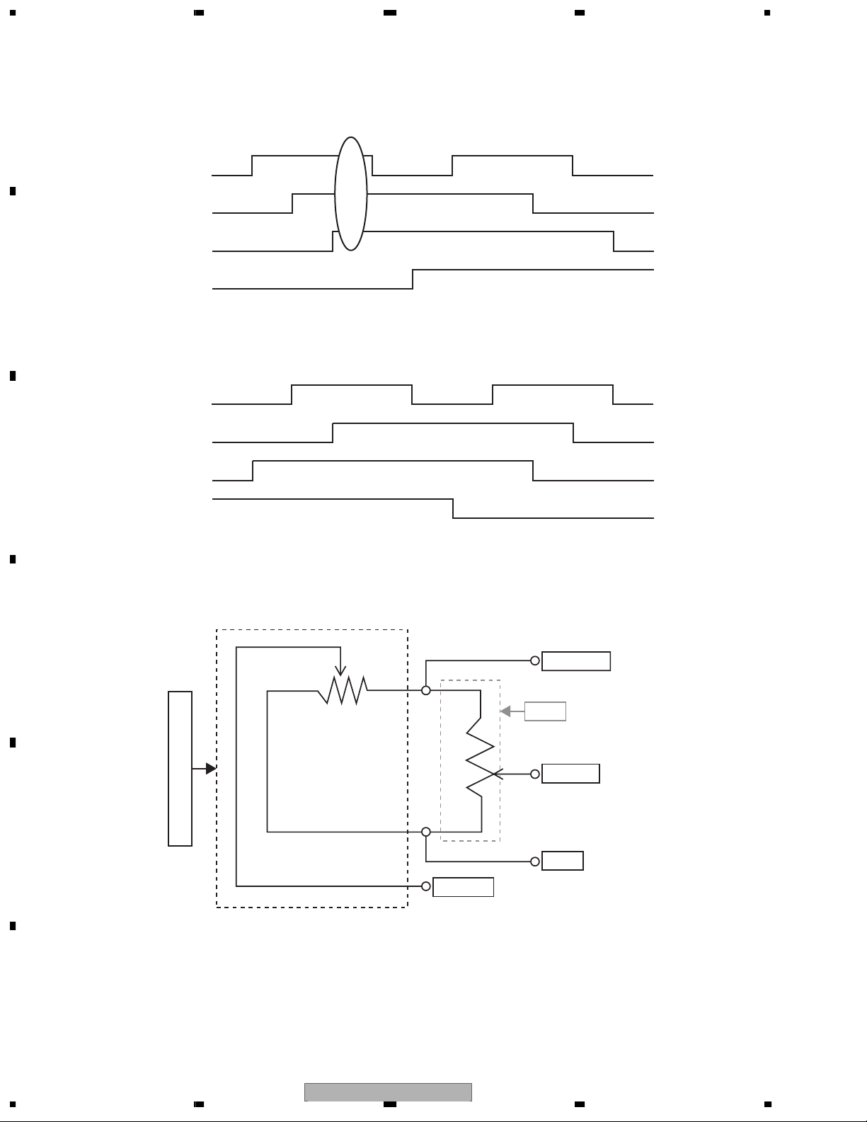
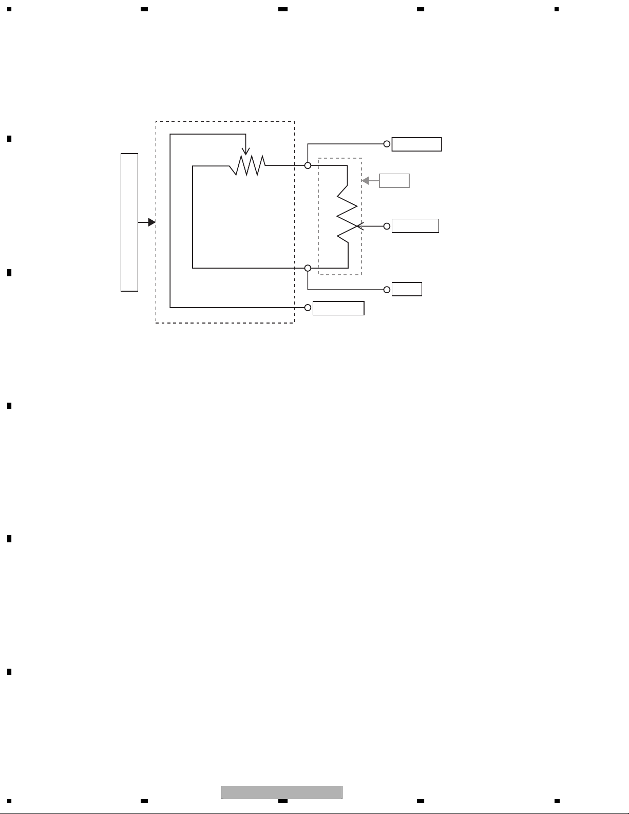
3.2 Elevation system
3.2.1 Detect system
It uses a linear position sensor (VR1), converts stage chassis level to voltage value and captures it by a microcomputer
A/D to detect absolute position.
Detect circuit
D
E
Linear position sensor
VR1
ELVSNS
SWDVDD
VR11
ELVREF
GND
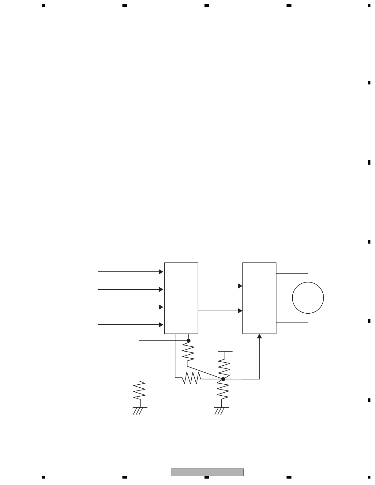
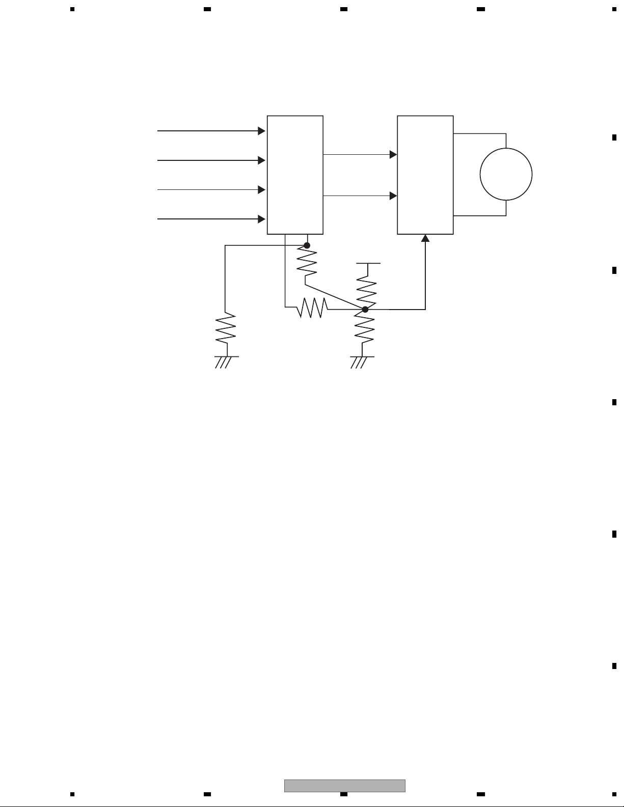
3.2.2 Drive system
Controlling an E/L motor by the control unit enables the following function.
Elevation function
F
1234
CX-315014
Page 15
5 678
a) Drive circuit
t controls drive direction by output E/LFWD, E/LREV from
the microcomputer (IC2001), and 3 values of drive voltage
by Hi-Z/H/L of E/LVOL2.
Driving upper direction E/L+>E/L- , (E/LFWD; H, E/LREV; L)
Driving lower direction E/L+<E/L- , (E/LFWD; L, E/LREV; H)
Drive voltage ( E/LVOL2=Hi-Z) ; 7.9V
( E/LVOL2=H) ; 7V ( E/LVOL2=L) ; 4.8V
A
LOADPHT
LOADSWR
LOADSWL
IN/SW
IC2001
98
58
MECHANISM
CONTROLLER
57
41
42
87
730
E/LVOL1 E/LVOL2
(no use)
E/LFWD
E/LREV
VD5PU
IC1240
4
3+3ch
DRIVER
5
8
E/L+
3
E/L
MOTOR
B
2
E/L-
C
b) Drive sequence
1 Driving continuously to the position of brake start.
2 Detecting of passing the position of brake start and starting short brake.
3 Starting of driving pulse to reach OK range. After confirmation of entering OK range, it is completed.
D
E
56
CX-3150
F
7
8
15
Page 16
1234
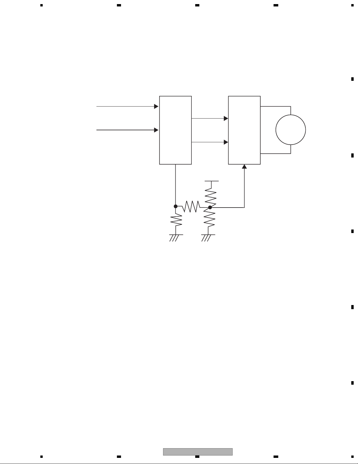
3.3 Camgear motor system
3.3.1 Detect system
A
B
It uses a rotary position sensor (VR2), converts a
camgear rotation angle to voltage value and captures
it by a microcomputer A/D to detect absolute position.
Detect circuit
SWDVDD
VR21
CAMREF
Rotary position sensor
VR2
GND
CAMSNS
C
3.3.2 Drive system
Controlling a cam gear motor by the control unit
enables the following function:
Open/close of shutter
Open /close of tray tab
Division of tray
Rotation operation of CRG chassis
(moving to the play position)
Release of mechanism lock
Drive of eject arm
D
E
F
CX-315016
1234
Page 17
5 678
a) Drive circuit
It controls drive direction by output CAMFWD and CAMREV
from the microcomputer (IC2001), and two values of drive
voltage by Hi-Z/H of CAMVOL.
Driving CRG chassis to the outer direction
(direction of EJECT position)
AM+>CAM-; (CAMFWD; H, CAMREV; L)
Driving CRG chassis to the inner direction
(direction of PLAY position)
CAM+<CAM-; (CAMFWD; L, CAMREV; H)
Drive voltage CAMVOL=Hi-Z; 8V
CAMVOL=H; 7V
A
VR2
VR21
CAMSNS
CAMREF
IC2001
94
95
MECHANISM
CONTROLLER
6
90
89
CAMFWD
CAMREV
IC1240
7
3+3ch
DRIVER
6
CAM+
34
35
9
CAM-
CAMVOL
VD5PU
b) Drive sequence
1 Driving continuously to the position of brake start.
2 Detecting of passing the position of brake start and starting short brake or reverse brake.
3 Starting of driving pulse to reach OK range. After confirmation of entering OK range, it is completed.
B
CAMGEAR
MOTOR
C
D
56
CX-3150
E
F
7
8
17
Page 18

1234
3.4 SPDL clamp system
3.4.1 Detect system
A
It is composed of two switches such as HOME switch used
in servo system (S1) and CLAMP switch (S2) for checking
a shutter of the tab inside it.
3.4.2 Drive system
It operates a pickup unit to move to inner side from normal
replay position and moves clamp mechanism of a DISC.
a) Drive circuit
B
S1
S2
C
D
HOME
CLAMP
IC2001
91
92
MECHANISM
CONTROLLER
SD2
3
IC1501
CD
CONTROL
74
70
SD1
SD0
VHALF
IC1240
32
3+3ch
DRIVER
36
19
20
CO-
CARRIAGE
MOTOR
CO+
E
F
CX-315018
1234
Page 19

Cam gear motor
Elevation motor
Carriage motor
Spindle motor
Tray separation operation
Carriage mechanism assembly rotation operation
Eject arm operation
Shutter opening/closing operation
Tray claw opening/closing operation
Elevation operation
Loading/ejection rollers rotation operation
Search operation
Disc clamp claw opening/closing operation
Disc rotation operation
2. MECHANISM OVER VIEW
2.1 STRUCTURE OF MECHANISM AND OPERATION OF COMPONENTS
The mechanism consists of three blocks, i.e., a main chassis, which is the base of the entire mechanism, stage and
tray. Various kinds of operations are performed according to how those blocks are positioned in relation to one
another.
The stage block consists of CRG, stage and loading unit; and the loading unit moves up and down with the stage
block. The stage block is joined to the main chassis section with a stair and link lever. Sliding the stair moves the
entire stage block moves up and down. Moving the link lever allows the CRG to rotate to play a disc. The tray block
consists of six trays. Similarly to the stage block, the tray block moves up and down as the stair slides.
To play the disc, the stage block moves toward the tray block at a location where the disc can be played. Then, the
tray group is separated by the action of cylindrical cams, the CRG is inserted and the disc is clamped.
To load or eject the disc, the stage block moves to its lower end. Then, the tray block moves the target disc to a
location where the disc can be loaded or ejected. The tray group is separated by the action of cylindrical cams.
Then, the disc is loaded or ejected.
To carry out the aforementioned operation, the mechanism is provided with four motors. The operations listed in the
table below are carried out by using the motors as a motive power.
Cam gear motor
Elevation motor
5 678
A
B
C
D
CX-3150
56
E
F
7
8
19
Page 20

1234
A
Carriage motor
Spindle motor
B
C
The operations carried out using the motors as a motive power are described below.
2.2 CAM GEAR MOTOR (OPERATION OF THE CAM)
The following five operations are carried out by using the rotary motions of the cam gear motor as a motive power.
D
E
a.Tray separation operation
b.Tray claw opening/closing operation
c.Carriage mechanism assembly rotation operation
d.Eject arm operation
e.Shutter opening/closing operation
Cam motor
Eject arm
Stage link lever
Cam gear
Cylindrical cam
drive gear
F
Eject driving arm
CX-315020
1234
Page 21

a.Tray separation operation
The rotary motion of the cam gear motor is transferred to the cylindrical cams by way of its cam. The tray is
separated by rotations of the cylindrical cams. This makes a space into which the CRG is inserted when playing
the disc. The mechanism of the cylindrical cams to separate the tray is as shown below.
In addition, the appearance of trays being separated at the time of loading or playing disc #3 is shown below as
an example.
Cylindrical cam, green: It is
mounted on the stage. It
moves up and down in
synchronous with the stage.
Cylindrical cam, yellow: It is
mounted on the upper tray holder.
It goes up-and-down in
synchronous with the holder.
Cylindrical cam, red: It is fixed on
the chassis.
Cylindrical cam, green: Used to select a
target tray
Cylindrical cam, yellow: Used to support the
tray at the time of loading a disc
Cylindrical cam, red: Used to support the
tray at the time of playing a disc
3F ELEV O.K.
(LOAD)
Stage 1F
Tray group 3F
DISC#3 LOAD
Stage 1F
Tray group 3F
3F ELEV O.K.
(PLAY)
Stage 3F
Tray group 1F
DISC#3 PLAY
Stage 3F
Tray group 1F
5 678
A
B
C
D
CX-3150
56
E
F
7
8
21
Page 22

1234
A
b.Tray claw opening/closing operation
To prevent a disc from dropping, each tray is provided with three claws for clamping the disc. When the
cylindrical cams rotate, the tray is separated and tray claws are simultaneously opened/closed.
Tray claw, right
B
Tray claw, left (2 pcs.)
C
c.Carriage mechanism assembly rotation operation
D stage link lever and CRG rotating lever are in mesh with each other. The CRG block rotates to travel to the
disc playing position in synchronous with the stage link lever movements. The CRG block is fixed with the CRG
lock arm and other components at the disc playing position.
CRG rotation lever
D
CRG rotation arm
CRG lock arm
E
F
CX-315022
1234
Page 23

d.Eject arm operation
At the time of ejecting a disc, the eject arm is rotated by the force transferred from the eject driving arm to push
the disc out.
e.Shutter opening/closing operation
ELEV 2 gear is slid by the force transferred from the eject driving arm. At the same time, the shutter, which
protects the disc insertion slot engaged with the ELEV 2 gear unit, opens/closes.
ELEV 2 gear unit :
It slides by the force transferred from the eject driving
arm.
5 678
A
B
C
D
E
56
CX-3150
F
7
8
23
Page 24

1234
2.3 ELEVATION MOTOR
A
The following two operations are carried out using rotations of the elevation motor as a motive power.
a.Elevation operation
b.Load/eject roller rotation
a.Elevation operation
Where the ELEV O.K. state, the stair is slid by rotations of the elevation motor. The stair is in mesh with the
tray block and stage block. Therefore, the tray block and stage block move up and down in synchronous with
the stair sliding.
The tray block and stage block change their positions among the following 11 ones according to a change in
the stair position. The stair position is detected by the linear position sensor.
B
Stair position
1
2
3
4
5
6
7
8
9
C
0
-
Stage block
1F
1F
1F
1F
1F
1F
2F
3F
4F
5F
6F
Tray block
6F
5F
4F
3F
2F
1F
1F
1F
1F
1F
1F
When the stair is located at one of positions 1 to 6 the stage does not move up and down but stays at 1F. In
this case, the tray group moves up and down to select a disc. To load or eject a disc, the stair should be located
at one of those positions.
When the stair is located at one of positions 6 to - the tray group does not move up and down but stays at
1F. In this case, the stage moves up and down to select a disc. To play a disc, the stair should be located at one
of those positions.
D
a.Elevation operation
When the stage is on its lowest layer, the roller drive gear joins the row of gears of the elevation motor. As a
result, the load/eject roller rotates as the elevation motor rotates. This draws/ejects a disc.
At the time of loading/ejecting a disc, the ELEV 2 gear slides to separate the row of gears which transfers the
stair force. Therefore the stair does not move.
Roller drive gear: It moves up and down simultaneously
with the stage.
E
ELEV motor
F
ELEV 2 gear: It slides.
CX-315024
1234
Page 25

2.4 CARRIAGE MOTOR AND SPINDLE MOTOR
When playing a disc, the spindle motor works to rotate the disc. Search operation is carried out by reducing the
rotating speed of the carriage motor with a worm and driving the feed screw.
At the time of playing, the disc is clamped with the three claws. The claws open to unclamp the disc when the
support wheel mechanism shifts the pickup to the support wheel, or the claws close to clamp it for the search
operation.
Pickup
Disc clamp claws (open)
Support wheel
Feed screw
5 678
A
B
C
D
E
56
CX-3150
F
7
8
25
Page 26

1234
A
2.5 DETECTION OF A DISC BY SENSORS AT THE TIME LOADING
A disc is detected by a phototransistor, right and left load switches and INIT switch.
Phototransistor: Light emitted by the LED mounted on the underside of the roller is reflected by the lighting
conductor on the shutter. When the light is shielded by the disc, the phototransistor is brought to its Hi status.
Load switch, right: It is mounted on the right side of the disc insertion slot. When the white resin lever is pressed to
the right by the disc, the switch is brought to its Hi status.
Load switch, left: It is mounted on the left side of the disc insertion slot. When the white resin lever is pressed to the
left by the disc, the switch is brought to its Hi status.
INIT switch: It is mounted at the right back of the stage. When the resin arm moves from its home position, the
switch is brought to its Hi status.
B
INIT switch
Load switch
Load switch
C
Phototransistor
D
The group of sensors recognizes the disc state as shown below.
Eject
Load
Hi
Photo
Lo
Detection
switch, right
E
Detection
switch, left
Hi
Lo
Hi
Lo
Hi
INIT SW
Lo
Loading starts
F
Loading completesEjection stops
1234
CX-315026
Page 27

2.6 OPERATIONS OF THE MECHANISM
The following operations are described below based on the explanation of a series of combined operations of the
elements given above.
Initial operation of the mechanism
Loading operation
Ejection operation
Play operation
2.6.1 Initial operation of the mechanism
When the power is turned on, the mechanism starts initialization. It checks all trays starting from #6 for the
presence of discs. The mechanism recognizes the tray(s) which currently has a disc.
2.6.2 Loading operation
Operation sequence from the ELEV O.K. state to the loading of a disc is carried out as described below:
1 Tray into which a disc is to be ejected is selected by moving the tray group up and down by the elevation
operation.
2 Tray separation and shutter opening actions are taken simultaneously by the cam operation.
3 When the user inserts a disc into the selected tray, the phototransistor detects the inserted disc.
4 The disc is drawn inside by rotary motions of the roller.
5 The disc drawn into the predetermined position is detected.
2.6.3 Ejection operation
Operation sequence from the ELEV O.K. state to the ejection of a disc is carried out as described below:
1 Tray from which a disc is to be inserted is selected by moving the tray group up and down by the elevation
operation. The tray from which the disc is to be ejected moves to the disc insertion slot.
2 Tray separation and shutter opening actions are taken through the cam operation. Then, the eject arm
actuates to push the disc forward. At the same time, the roller starts rotating.
3 The disc is ejected by rotary motions of the roller.
4 It is detected that the user draws out the disc from the slot.
5 The steps 1 and 2 are carried out in reverse order by the cam operation. This closes the shutter.
2.6.4 Play operation
Operation sequence from the ELEV O.K. state to the play state is carried out as described below:
1 The stage moves to the position of the tray which has the disc to be played by the ELEV operation.
2 Tray separation and CRG rotation actions are taken by the cam operation.
3 The disc is clamped.
5 678
A
B
C
D
56
CX-3150
E
F
7
8
27
Page 28

1234
A
The aforementioned operation sequence is reversed to shift from the play state to the ELEV O.K. state.
Disc changing is carried out by shifting from the current play state to the ELEV O.K. state once, then shifting to
the next play state. For example, to change the disc 1 to disc 6, the disc 1 play status is shifted to the ELEV O.K.
status first, then the ELEV O.K. state is shifted to the disc 6 play state.
The mechanism state transition diagram is given below. Transition of the state of stage and tray group by the
elevation operation is presented in vertical direction of the diagram. Transition of the state of tray separation and
CRG position by the cam operation is presented in horizontal direction of the diagram. As shown in the diagram,
the position of tray group and stage at the time of loading and ejection is same with that at the time of play only in
the case of the disc 1.
B
Play
position
Tray separation/CRG rotation
ELEV O.K.
position
Vertical: ELEV operation
Horizontal: Cam operation
6F Play height
ELEV operation:
STG elevation
Position detected by the linear position sensor
1F Play & loading height
C
Tray groups
elevation
Cam operation:
Position detection by the rotary position sensor
6F Loading
height
Loading
position
D
E
Eject
position
Linear position sensor Rotary position sensor
F
CX-315028
1234
Page 29

3. DISASSEMBLY
3.1 PREPARATION FOR REMOVAL
1 Place the mechanism in the ELEV O.K. state.
2 Eliminate static electricity with a wrist band, etc.
3 Carry out short-soldering. (There are two points to be short-soldered. It is enough to solder one of them.)
4 Slide the lock section of the connector to fix a flexible cable and remove a flexible cable. (2 points)
Short-soldering
Shield plate
5 678
A
B
C
D
E
56
CX-3150
F
7
8
29
Page 30

1234
A
3.2 HOW TO REMOVE THE UPPER CASE
1 Remove poly washer. Remove the ELEV 4 gear.
Once the ELEV 4 gear is removed, the stair can be slid as desired.
Stair
B
ELEV 4 gear
*In the illustration above, the ELEV 3 gear is removed. But the ELEV 3 gear is not required to be
removed.
2 Manually slide the stair (clockwise) to raise the stage block to the uppermost floor.
C
3 Remove front right spring A.
4 Change the position of the back left spring B from the home position to a temporary position. (The hook at
the temporary position is fixed on the stage. This means that the stage needs to be raised to the
uppermost floor to enable easy re-positioning of the spring.)
R
2
Arm
D
4
Spring B
L
Home position
E
Temporary position
Front
3
F
Spring A
F
CX-315030
1234
Page 31

4 Manually slide the stair to lower the stage.
5 Remove four screws which are used to secure the upper case. Remove the upper case.
6 Lightly slide the snap-fitted top arm to remove it.
Top arm
This screw is not required to
be removed.
1
2
3
4
5 678
A
B
C
D
E
CX-3150
56
F
7
8
31
Page 32

1234
A
3.3 HOW TO REMOVE THE STAIR
1 Slide the stair in the direction for lowering the tray block until it will go no further. (See the photo shown
below.)
B
2 Remove three stairs.
Direction of slide
C
D
E
F
1234
CX-315032
Page 33

5 678
3.4 HOW TO REMOVE THE STAGE
1 Desolder the back right cam motor. Then, remove the flexible cable.
2 Draw out the stage block in vertical direction.
3 Lift up the triangular top plate in the vertical direction, then slide it away from you until it comes off.
4 Remove the tray and cylindrical cam from the stage.
3
2
Desolder this part.
A
B
C
D
E
56
CX-3150
F
7
8
33
Page 34

1234
A
3.5 HOW TO REMOVE THE LOAD FRAME
1 Remove the springs from both sides of the roller. Remove the roller.
2 Desolder and remove the flexible cable.
3 Remove the screws which are used to secure the load frame at four points. Remove the load frame.
Note: Remove springs from metal plate hook, but not necessarily from the resin collar.
2
1
B
Screw
Screw
C
Screw
Screw
D
3.6 HOW TO REMOVE THE CRG
(ONLY FOR REFERENCE SINCE THIS PROCEDURE IS HARD TO BE
COVERED BY OUR SERVICE)
E
F
1 Slide the part with which the stage link lever is in mesh toward you. Turn the CRG to move it to the play
position.
2 Remove the resin part and springs.
3 Remove the CRG.
1234
CX-315034
Page 35

5 678
3.7 HOW TO REMOVE THE ELEV MOTOR
1 Check that the ELEV3 gear is removed.
ELEV3
2 Remove the solder of two lines (red and white) on the rear side of main chassis.
A
B
C
3 Unscrew the three screws shown in the figure.
D
E
F
56
CX-3150
7
8
35
Page 36

1234
A
4 Remove the resin part. At this time, it can be removed easily by applying edgewise pressure to
the point shown in the figure using the straight slot screwdriver.
B
5 Pull out the gear shaft, and remove the gear.
C
D
6 Unscrew the two screws fixing the motor and remove the wire lead.
E
F
CX-315036
1234
Page 37

5 678
4. HOW TO ASSEMBLE
4.1 CHECK BEFORE ASSEMBLING
·
Check the location of CAM gear of main chassis.
As shown in the photo below, check that the hole of main chassis can be seen from the hole of
cam (it is not necessary to match it perfectly).
Location of CAM gear
·
Check the location of stage lock arm of STG. It is not like as shown in the figure below, move the
arm to the position of mark. In a similar way, for the white resin part, move the arm to the position
as shown in the photo below.
A
B
C
Location of STG lock arm
Contacting
D
Positioning to the mark
E
F
56
CX-3150
7
8
37
Page 38

1234
A
At this time, check the part pointed in the figure does not drop off the groove.
When it is dropping off the groove, set it paying attention to the position shown in the photo below.
B
C
Location to attach the white resin
D
E
F
1234
CX-315038
Page 39

5 678
4.2 ASSEMBLING THE ELEV MOTOR
(When the ELEV motor is not removed, this step is not necessary)
·
Press the gear into motor, and attach the wire lead.
Connect the white wire lead to the white mark side on bottom panel of motor.
Mark on bottom panel of motor
A
B
C
How to connect the wire lead
·
Fix the motor to the bracket with screws.
How to fix the bracket
D
E
F
56
CX-3150
7
8
39
Page 40

1234
·
A
Fix the resin part to the main chassis.
Hook the tip of
resin part
B
Insert this prong to the hole of resin
How to fix the resin part
·
Secure the three screws.
C
How to fix the ELEV motor unit
D
·
Solder the wire lead to the board on the rear side of main chassis, and fix it with tape.
tape
E
RD: red
WH: white
F
CX-315040
1234
Page 41

5 678
4.3 ASSEMBLING THE CAM MOTOR
·
Press the gear into motor, and fix it to the bracket with two screws.
At this time, take care of the direction to fix the gear. Check the location of mark is as shown in the photo
shown in lower right.
Mark
How to fix the motor
·
Attach the CAM gear, and fix the CAM motor unit with two screws.
Mark for attaching the motor
A
B
C
CAM gear
Location to attach the CAM gear
D
Location to attach the CAM motor unit
E
F
56
CX-3150
7
8
41
Page 42

1234
4.4 ASSEMBLING THE STAGE UNIT
A
1 Prepare the tray.
Pile the 6 trays so that the tray with steel plate is at the bottom.
B
Tray (6-pile)
2 Prepare the STG.
Attach the cylinder cam OUT to the stage.
At this time, attach the black cylinder cam at the right back.
C
D
Location to attach the cylinder cam OUT
Rotate the matched cylinder cam and match the marks of STG and cam (for all cams).
E
Left back Right back
Left front
Location of mark of cylinder cam OUT
F
CX-315042
1234
Page 43

5 678
3 From rear side of main chassis, insert the assembly jig to the cylinder cam gear (x3).
Assembly jig
GGF1538 x 3
A
B
C
After inserting the assembly jig
D
E
F
56
CX-3150
7
8
43
Page 44

1234
A
4 Insert the cylinder cam IN (x3).
At this time, set the key part of cylinder cam gear to the key groove of inside of cylinder cam IN.
Match the tip of assembly jig to the depressed portion on the bottom panel of cylinder cam IN.
Key groove
Depressed portion
Key part
B
Cylinder cam IN Cylinder cam gear
C
5 Attaching the STG.
At this time, as the right front part does not have a bracket, support it with something.
D
After attaching the STG
E
F
1234
CX-315044
Page 45

5 678
At this time, check the three parts shown in the figure below fit.
*Especially, for the right panel, take care so that the metallic bar protruding from the main chassis fits the
both of stage link lever and white resin part.
Left front Right front *Right panel
* In this operation, take notice that the cylinder cam whose mark is matched in step 2 may jolt out
of alignment. If it jolts out of alignment, reposition the key groove and mark.
6 Place the tray. At this time, the tray pin should be inserted to the location shown in the figure.
A
B
C
State of attached tray
D
E
F
56
CX-3150
7
8
45
Page 46

1234
A
7 Insert the tray holder.
Insert the tray holder to the tip of cylinder cam IN, and then slide it to forward and fix it. At this time,
take notice that the black sheet on the rear side of tray holder sticks easily in the tray.
Check it is properly set (3 parts) as shown in the figure at lower right.
B
Slide
Direction to slide the tray holder Tray holder rigid part
C
8 Pick up the main chassis slowly, and pull out the jig.
D
E
F
The STG unit is properly assembled
1234
CX-315046
Page 47

5 678
4.5 FROM ATTACHING THE CASE ABOVE TO COMPLETION
1 Attach the front stair.
Check that is properly set (5 parts) as shown in the figure below.
Next, slide the attached stair to left side slightly (figure below).
A
B
C
2 Attach the stair on left side safe.
Check that is properly set (6 parts) as shown in the figure below.
D
E
F
56
CX-3150
7
8
47
Page 48

1234
A
3 Attach the rear stair.
Before attaching the rear stair, slide the Potentiometer on the rear panel to the location shown
in the figure below.
B
Attach the stair.
Check that the eight positions shown in the figure below are properly set.
C
D
* When attaching the front stair, fix the front side to the upper panel, and when attaching the left
panel stair and rear panel stair, fix the side panel to the upper panel.
·
Slide the stair to the left.
Check the all stairs are fitted in the groove, and slide the stairs to the left.
E
F
1234
CX-315048
Page 49

5 678
A
4 Solder the two cam motors.
B
5 Check the side panel flexible cable is not removed.
C
D
56
CX-3150
E
F
7
8
49
Page 50

1234
A
6 Fit the shutter and upper case, and attach it to the mechanism unit.
Upper case
Shutter
* As shown in the figure below, it is easy to assemble the unit by fitting the right side opening
B
the shutter and right side after fitting the left side. The state of mechanism is recommended to be
at 1F play position.
C
How to attach the upper case
D
E
Hook the detection lever of front to the rear side of front panel of shutter.
* Push the detection lever to the left side lifting the left part of upper case.
Normal
Abnormal
Location of detection lever
F
1234
CX-315050
Page 51

5 678
7 Secure the screws.
Secure the four screws on the panels below.
Left panel
A
B
Rear panel
Right panel
C
D
E
56
CX-3150
F
7
8
51
Page 52

1234
A
8 Lift the stage to the top floor by sliding it, and hook the spring at left back.
Hook the spring which is temporarily hooked to the A part to B part.
B
Spring of left back part
* If failing to hook the spring, remove the STG again, and hook the spring again as shown
in the photo below.
C
D
Left back part of stage frame
E
F
1234
CX-315052
Page 53

5 678
9 Hook the right front spring.
Hang the spring on the hook shown in the figure below.
Right front spring
0 Attach the top arm.
As shown in the figure, attach it sliding it aside after insert it vertically from above.
A
B
C
A stage mechanism is lowered.
(Since the stage mechanism has been raised with 8, a top arm is not attached unless it lowers.)
As shown in the photo below, press it with a finger, and set it as shown in the right figure.
D
E
F
56
CX-3150
7
8
53
Page 54

1234
A
B
! When the ELEV3 gear is removed, set it by pressing as shown below.
ELEV3 gear
Attach the ELEV4 gear, and fix it with poly washer.
C
D
E
F
@ Insert the two flexible cable as shown in the figure below, and slide and lock the claw,
and then remove the short-soldering.
1234
CX-315054
 Loading...