

PIONEER CU-VSX128 Service Manual
VSX-D607S
58
•
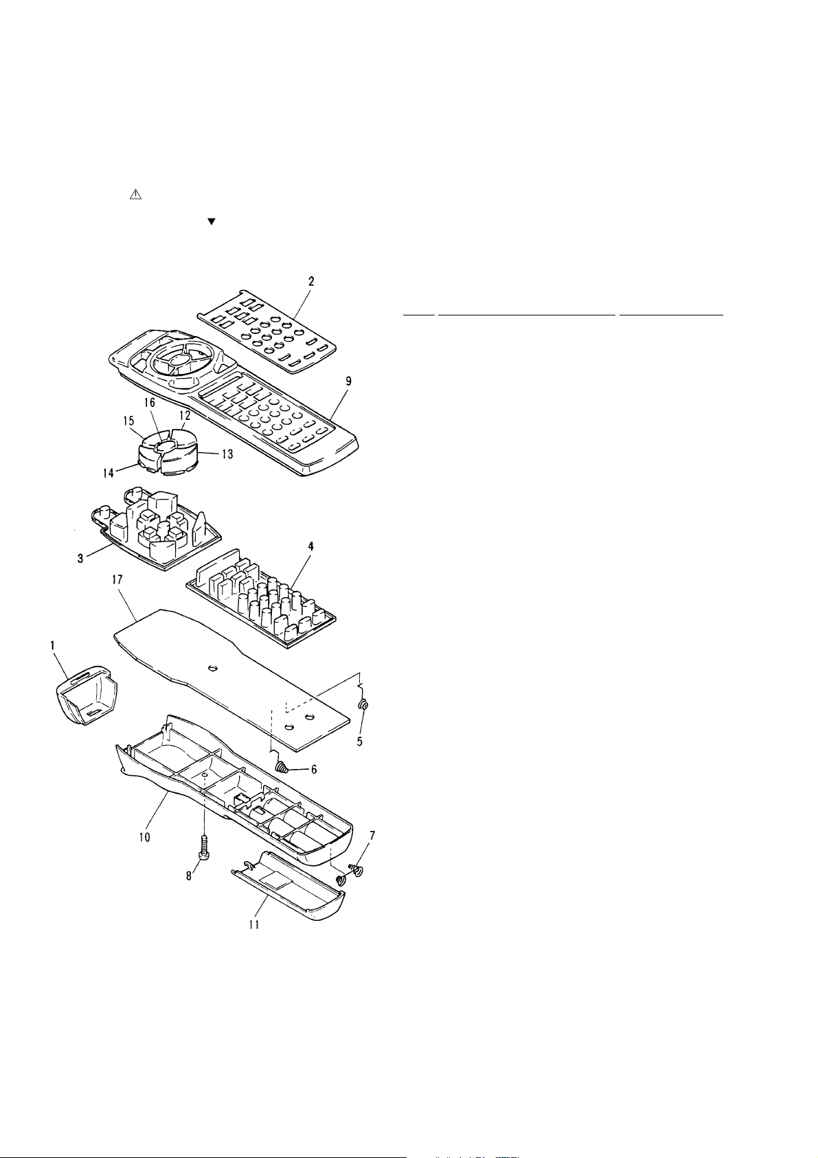
Parts List
Mark No. Description Part No.
1 Filter AZA7152
2 Name Plate AZA7283
3 Rubber Sheet (A) AZA7236
4 Rubber Sheet (B) AZA7243
5 Spring (+) AZB7049
6 Spring (–) AZB7050
7 Spring AZB7051
8 Screw AZB7052
9 Remo-con Case (A) AZN7672
10 Remo-con Case (B) AZN7326
11 Battery Cover AZN7327
12 Main Key (FF) AZN7666
13 Main Key (STOP) AZN7329
14 Main Key (REV) AZN7665
15 Main Key (PAUSE) AZN7331
16 Main Key (PLAY) AZN7664
NSP 17 PCB AZW7243
7.4 REMOTE CONTROL UNIT [CU-VSX128 (AXD7153)]
7.4.1 EXPLODED VIEWS AND PARTS LIST
NOTES:• Parts marked by "NSP" are generally unavailable because they are not in our Master Spare Parts List.
•
The
mark found on some component parts indicates the importance of the safety factor of the part.
Therefore, when replacing, be sure to use parts of identical designation.
•
Screws adjacent to mark on the product are used for disassembly.
VSX-D607S
59
A
B
C
D
1
234
1
2
3
4
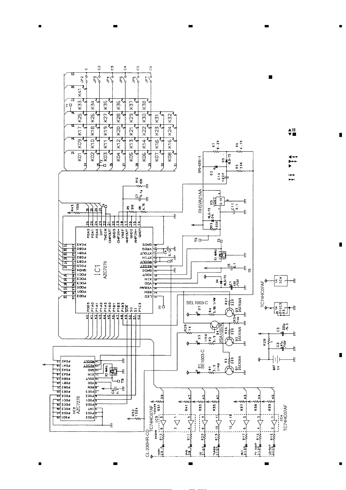
7.4.2 SCHEMATIC DIAGRAM
Note : When ordering service parts, be sure to refer to "EXPLODED VIEWS and PARTS LIST" or "PCB PARTS LIST".
K01 : 0
K02 : 1
K03 : 2
K04 : 3
K05 : 4
K06 : 5
K07 : 6
K08 : 7
K09 : 8
K10 : 9
K11 :
K12 :
K13 : SET UP
K14 : MODE CHK
K15 : MULTI OPE.
K16 : SYS. OFF
K17 :
K18 :
K19 : ENT.
K20 : POWER
K21 : CHK22 : CH+
K23 : DISC
K24 : +10
K25 : VOL.K26 : VOL.+
K27 : TV FUNC.
K28 : TV POWER
K29 : AMP POW.
K30 : MUTING
K32 : FUNCTION
K33 : DVD
K34 : LD/SAT
K35 : CD
K36 : VCR1
K37 : TV CONT.
K38 : TUNER
K41 : SURROUND
SWITCHES
 Loading...