


CT-A9
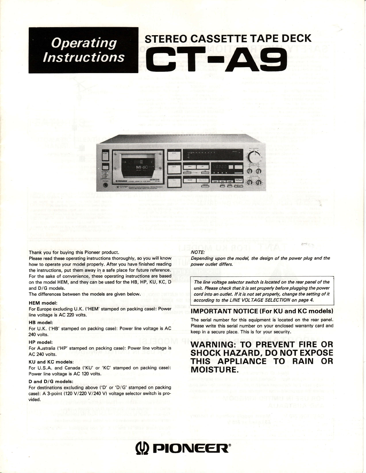
STEREO
CASSETTE
GT-A9
TAPE
DECK
you
Thank
Please
how to operate
the instructions,
For the sake of convenience, these operating
on the model
and
The differences between the models are
HEM model:
For Europe excluding U.K.
line voltage is AC 220
HB model:
For
240 volts.
HP model:
For A.rstralia
AC 221.0 volts.
KU and KC
For U.S.A. and Canada
Power line voltage is AC 120
D and
For destinations excluding above
case): A 3-point
vided.
for buying this
these operating instructions
read
D/G models.
U.K.
your
model
put
them away
HEM, and they can be used
volts.
('HB'
stamped on
('HP'
stamped on
models:
D/G models:
(120
V
/220 V /240
('KU'
Pioneer
properly.
in,
('HEM'
packing
packing
or
volts.
('D'
product.
thoroughly, so
you
After
place
a safe
for
given
stamped on
Power line voltage
case):
case):
'KC'
stamped on
or 'DlG' stamped on
V)
voltage selector
you
will
finished reading
have
for future reference.
instructions are
HP, KU, KC, D
the HB,
below.
packing
case):
Power line voltage
packing
packing
switch
know
based
Power
is AC
is
case):
pro-
is
NOTE:
Depending
power
The
unit. Please
cod into an
according
upon the model, the
outlet differs.
line vottage
selector
check that
outlet.
to the LINE
it is set
lf it is not set
VoLTAGE SELECTION
IMPORTANT NOTICE
The
serial number
Please
write this serial number on
keep in
a secure
WARNING:
for
this equipment
place.
This
TO PREVENT
design
of the
switch is located on the
properly
is for
before
properly,
(For
KU and KG
is located on the
your
enclosed
your
security.
change
SHOCK HAZARD, DO NOT
plug
power
panel
rear
plugging
the setting of
page
on
the
4.
models)
rear
warranty card
FIRE OR
EXPOSE
and the
of the
power
it
panel.
and
THIS APPLIANCE TO RAIN OR
MOISTURE.
(D
rrloNEEFl'
SAFETY
INSTRUCTIONS
READ
operating
appliance
INSTRUCTIONS
RETAIN
tions should
WARNING
HEED
in the
and
to.
INSTRUCIIONS
FOLLOW
instructions
AND
WATER
be used
not
bathtub,
wet ba$ment,
LOCATION
stable
oR CEILING
WALL
should
VENTILATION
its
that
propsr ventilation.
its
should
similar
or,
ings;
bookcase
through
sir
The
HEAT -
heat sources
stoves,
produce heat.
that
SOURCES
POWER
nected
in the
ed
aooliance.
POWER-CORD
should
walked
against
plugs,
at
where
instructions
is ogerated.
operating
washbowl,
-
location.
not
location
not be
surface
plsced
or
appliance
or other
to a
operSting
be
on
them,
convenience
thev exit
be retained
All
instructions
be
should
MOISTURE
water
near
kitchen
near a
or
appliance
The
MOUNTING
mounted
be
The appliance
position
or
situated
may block
that
in a built-in
that
cabinet
the ventilation
should
as
such
appliances
The
-
power
supply
instluctions
PROTECTION
so
routed
pinched
or
psying
trom
should
warnings
tollowed.
For example,
that
particular
the appliance.
INSTRUCTIONS
All
be
operating
The
for future
should
opeEting
All
-
The appliance
for example,
sink,
ilimming
should
wall or
to a
should
does
a bed,
on
the
installation,
impede
may
openings.
be situated
radiatoE,
{including
appliance
of the
only
or
Powersupply
-
they are
items
by
receptacles,
safetv and
the
before
read
reference
the appliance
on
be
laundry
pool,
installed
b€
The appliance
ceiling.
situated
be
not interfere
the appliance
sofa,
v€ntilation
such
the Jlow
away
reg'sters,
heat
amplifiers)
should
type de$rib-
as marked
likely
not
placed
attention
the
and
the
instruc-
adhered
use
and
should
near a
tub, in a
etc'
in a
with
rug.
open-
as a
from
be con-
on
cords
to be
upon
to cords
point
so
or
ot
the
or
CLEANING
with I
clean
other
cabinet.
LINES
POWER
lo€ted away
NONUSE
pliance
left unused
OBJECT
taken
spilled
DAMAGE
should
center or aualified
.
power-supply cord
The
damaged;
.
Objects
the appliance;
.
The aoDliance
.
aDpliance
The
or exhibits
.
The applianc€
damaged.
SERVICING
the applisnce
operating
the nearest
tact
OUTDOOR
antenna
the antenna
sure
vide some
up static
built
ln the U.S.A.
Code,
with respect
tion
and supporting
to an antenm
wire
ding
unit.
quirements fo.
-
polishing
furniture
with
volatile
PERIODS
should
AND LIOUID
that objects
so
into
REOUIRING
be rerviced
or
have
I
-
instructions.
ANTENNA
is connected
ANSI/NEPA
conductors,
connection
IFOR
The appliance
the enclosure
or a
cloth
wax,
liquids since
An outdoor
power
from
The
-
be unplugged
period
tor I long
ENTRY - Care should
do
SERVICE -
Pioner authorized
by
sNice
or liquid
fallen,
or
has been
not appear
do6
change
marked
has ben
user should
The
beyond
For all
Pioneer
GROUNDING
to
systsm
protaction
against
charges
810
section
No.70-1S1,
proper groundig
to
structure.
discharge
location
grounding
to
grounding
the
KU MODEL]
corrode
the
The appliance
seryice
when:
plug
has b@n
spilled
normally
to sryice
in the
center.
outside
- Itan
terminal, be
to
so as
surg6
informa-
of the
lead-in
ot the
groun-
ot
size
only
the
ap-
not
into
or
pro-
and
mast
Fig.
or
be
be
re-
should be cleaned
soft dry cloth. Never
benzine, inssticides
they m8y
antenna should
lins.
power
cord of
from the outlet when
of time.
not fall and liquids are
through openings.
personnel
or the
has been
to rain; or
exposed
to operate
performance;
in
or the enclosure
dropped;
not
attempt
that d,escribed
bther srvicing, con-
authorized sryice
the antenna
grounded
is
voltage
ot the Nstional Electrical
provides
grounding
unft,
o{ antenna-discharge
electtodes, and
electrode. See
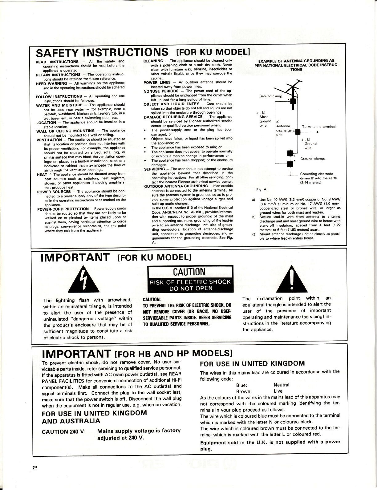
NATIONAL
Ground clamp
b)
Mast
ground
10 AwG
No.
(8.4
mm2l aluminum
copper-clad
ground
wires for both
lead-in
unit and
dischsrge
insutators,
stand-off
to 6 teet
mete.s)
to where
ble
OF
EXAMPLE
PER
a),
a) Use
b) Secure
c) Mount sntenna
ANTENNA
ELECTRICAL
TIONS
To
a), b)
Ground
Grounding electrode
ii
driven 8' into
(2.'M
(5.3
mmr) copper or
or No.
or bronze
steel
mast and
wire from antenna
ground
mast
sDaced
(1.88
meters) apart.
unit as
discharge
lead-in
enteF
GROUNDING
INSTRUC.
CODE
Antenna terminal
I
Ground
clamps
the
meters)
No. 8 AWG
(1.0
17 AwG
larger as
wire. or
lead-in
to Sntenna
house with
wire to
leet
lrom 4
closEly as
house.
AS
earth
mm'?)
l'1.2
po$i-
IMPORTANT
with
lightning
The
an
within
to alert
uninsulated
product's
the
sufficient
of electric
flash
equilateral
the user
triangle,
the
of
"dangerous voltage"
to constitute
to
Persons.
that
enclosure
magnitude
shock
Presence
IMPORTANT
prevent
To
viceable
electric
parts
inside,
lf the apparatus
FACILITIES
PANEL
component(sl.
torminals
signal
make sure
when
FOR USE
AND
CAUTION
that
the
equipment
IN
AUSTRALIA
240
is fitted
Make all
first. Connect
power
the
UNITED
V:
do
shock.
refer servicing
with AC
for convenient
connections
switch
in regular
is not
Mains
adjusted
IFOR
arrowhead,
is intended
of
within
may be
of
risk
a
IFOR
remove cover'
not
qualified
to
power
main
connection
to the AC
plug
the
to the wall
is off. Disconnect
use, e.g.
KINGDOM
supply
voltage
at24oV.
MODEL]
KU
CAUTIOl{:
TO PREUE]UT
REftovE
ftoT
SERVICEABTE
OUALIFIED
M
AND
HB
No user
personnel'
service
outlet(s),
see
of additional
outlet(s)
socket
the wall
on vacation'
when
factory
is
CAUTI()N
EIfGTBIC SHOCK,
OF
THE RSK
covER
PARIS
SERYICE
HP
ser-
REAR
Hi-Fi
and
last,
plug
BAcl0. tlo
loR
REFER
I]ISIDE.
PERIIO]II{EL
MODELS]
FOR USE
The wires
following code:
As the colours
not
minals in
The wire which
which is
The wire
minal which
Equipment
plu9.
DO
usEs
SERVICII{G
IN UNITED
in this
of the
correspond
plug proceed
your
is coloured
marked with
which
is marked
sold
The
equilateral
user
operating
structions
the appliance.
lead are
mains
Blue:
Brown:
wires
the coloured
with
the letter
is
coloured
with the
in the U.K.
exclamation
triangle
the
of
Presence
maintenance
and
literature accompanying
the
in
KINGDOM
coloured
Neutral
Live
mains
in the
blue
marking
follows:
as
must be
N or colouretr
must be connected
brown
letter L or
not
is
Point
is intended
of
(servicing)
in accordance
this apparatus
lead of
identifying
connected
black.
coloured
supplied
to
alert
an
the
within
imPortant
in-
with
the
to the terminal
the
to
red.
power
a
with
the
may
ter-
ter-
2
CONTENTS
Features
Line Voftage Selection
Rear Panel Facilities and Connections
Front Panel
Facilities .......-.............6
Recording
AUTO BLE Tuning System
....................3
..................4
............... 5
................10
...........12
Playback ..................13
FEATU RES
LENT-LOADI
AUTOMATIC
SI
MECHANISM
The use
possible
thorough attention
selection
assembly,
as
of an optical cassette
easy-to-operate
of materials
in order
possible.
has been
to
assure
detector and
auto loading and
paid
to
for motor drive
that the mechanism operates
MOL BALANCE CONTROL
Differences
the AUTO BLE bias adjustment
quency
with
AUTO BLE: An abbreviation
Tuning
MOL:
AUTO
For simplified
recording. This
and source
FEATHERTOUCH.
wrTH
The unit
servo controller
to fast forward,
TAPE SLACK
With
closes,
slack.
DOLBY
ln addition
equipped
reduction effect for even
in the frequency spectrum
response and dynamic
tape.
System.
An abbreviation
point
range
for Automatic Bias, Level and
for Maximum
MONITOR
operation of
feature allows
monitor merely by
the bothersome monitor switch
you
pressing
EASE OF OPERATION
tc Loclc
joy
is
to operate, with sure.
a
mechanism, allowing direct
rewind.
PREVENTION
the tape slack
the takeup reel automatically
NR B. C SYSTEMS
to the
with
prevention
previous
the
Dolby
Dolby B
NR
C
greater
function, when
type
fidelity of sound
MPX FILTER
the Dolby NR system,
Using
for more effective
OFF
the MPX filter can be switched
noise reduction with FM stereo
NG
shift mechanism
power
eject. In
all aspects
of construction,
transmission
parts,
TYPE AUTO
of the music source
in
3 stages.
the maximum
at
Output
to
switch
the operating switch.
microcomputer digital
This allows a
limits allowable
Level.
between
transition from
tape monitor
FUNCTION
the
revolves to eliminate
noise reduction system,
system and
cassette
its superior
reproduction.
broadcasts.
as silently
the unit
makes
addition,
from
to final
BLE
changes
flat fre-
Equalizer
during
feedback
playback
holder
tape
any
is
noise
to
or
ON
Using the Accessory Functions
Recording
the
Audio Timer ........
Maintenance
Troubleshooting ..........
Playback Using
and
.................
.............17
..............18
CassetteTapes
Specifications .............
BUILT-IN
The music
gram
on a
DUAL MODE
The four-digit
for
displaying the time remaining on
counter
TIMER
RECORDING
When
favorite music,
The
AUTO BLE timer recording function
recording.
MUSIC SEARCH
function is convenient for
search
tape,
or when
performing
COUNTER
digital display can be
display.
FUNCTION ALLOWS
WAKEUP
OR
with
used
an
perform
or
optional
automatic
audio
repeat
used either as a
the
timer,
tape
..............20
FUNCTION
locationg a
play
of a certain
tape, or as a
ABSENTEE
PLAYBACK
you
can wake up
tuning
and
gives you
CLOSED LOOP, DUAL CAPSTAN
This mechanism
rollers.
ternal
letting
PLL D.D. motor is
coreless type.
travel
Tape
vibration. Wow and flutter, and
you
enjoy even
THREE.HEAD
SENDUST
Since a
3-head
erasing heads is
recording, thus
Sendust, developed
used in the combination recording/playback
per
windings are
a special alloy with high efficiency
performance
the full
fully
demonstrated, delivering
superb sound
DC
AMPLIFIER
A DC
dynamic range is
is a low noise
section is a shunt type + 2
quality.
amplifier,
dual FET
the tape
drives
greatly
is
greater
the reel motor is a super-low
used,
SYSTEM
HEADS
system, using
you
used.
allowing
used
with superb
used
can
you
through
Pioneer's
playback
in the
high-ou.tput tapes.
of
for the
differential 2-stage
power
two sets of capstans and
using
stabilized
clarity of
independent recording,
to check
tone
playback
in order to shut out any exmodulation noise is
tone.
the
In
USING
monitor the
head,
for small wi;rdow use,
the dynamic energy
and
unit composition.
RIBBON
playback
the recording status.
magnetics technology,
own
head, while
the erasing
and
including metal
phase
equalizer amp.
type
amp,
......14
16
..........19
particular pro-
program.
real time counter
recording start.
more freedom
normal
to
tape
your
DRIVE
pinch
reduced.
quartz
a
capstan
torque ripple
playback,
while
sound
Ribbon
anoxic cop-
head uses
result,
As a
tapes, is
of sound with
characteristics
The
while
first
the
stage
power
for
and
is
and
AUTO
The automatic
val of 4 seconds at
the recording standby
ting out
recording and editing.
RECORDING
recording
one touch,
commercials
MUTE FUNCTION
mute function
then
mode. This function
and unwanted
creates
automatically
narration during FM
a non-recorded
returning
is
very convenient
inter-
to
the unit
for cut-
broadcast
LINE
VOLTAGE
SELECTION
(D
and
D/G
models only)
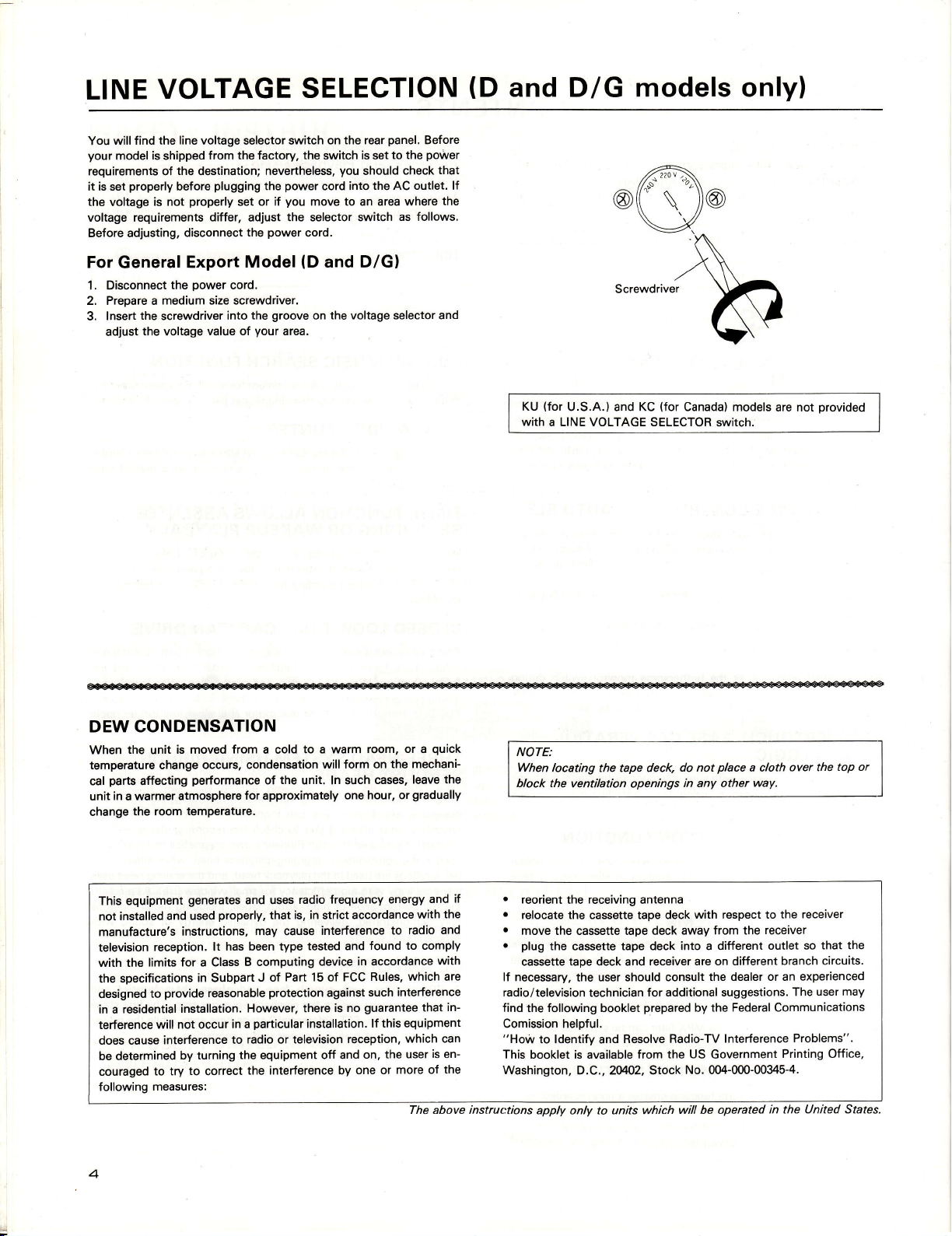
find the line voltage selector switch
You will
your
requirements of
it is
the
voltage requirements
Before adjusting,
For
1. Disconnect
2. Prepare a
3.
is
model
properly
set
is not
voltage
General
the
lnsert
the voltage
adjust
shipped
the
destination;
before
properly
disconnect
Export
power
the
medium size screwdriver.
screwdriver
from the factory.
plugging
differ,
nevertheless,
power
the
you
if
set or
the selector switch
adjust
power
the
Model
cord.
groove
the
into
value of
your
area.
on the rear
the
switch
you
cord into
move to an area where
cord.
(D
and D/Gl
the voltage selector and
on
panel.
is
to the
set
check
should
the AC outlet. lf
as follows.
Before
poriver
that
the
KU
U.S.A.) and KC
{for
With
A LlNE VOLTAGE SELECTOR
(for
Canada} models
SWitCh.
are not
provided
DEW CONDENSATION
the
When
temperature change
parts
cal
unit in a warmer
change
This equipment
not installed
manufacture's
television
with the
the specifications
designed
residential
in a
terference
does cause
be determined
couraged
following
is moved from a cold
unit
affecting
the room
reception.
limits for a Class
to
will not occur
to try
measures:
occurs, condensation
performance
atmosphere
temperature.
generates
and used
instructions,
in Subpart
provide
installation.
interference
turning
by
to
correct
of
for
approximately
and uses
properly,
may cause
has been type
lt
B computing
J of
reasonable
protection
However, there
particular
in a
radio
to
the
equipment
the interference by
the
that is,
Part 15
or
to a warm room,
will form on
unit. In such
radio frequency
in
strict
interference
tested and found
device
of
against
installation.
television
off and
cases,
hour, or
one
accordance
in
accordance
Rules. which are
FCC
such interference
guarantee
is no
lf this equipment
reception.
on, the
one or
quick
or a
the mechani-
leave the
gradually
if
and
energy
with the
to radio
and
to comply
with
in-
that
which can
is
user
more of the
en-
The above instruc:tions
NOTE:
When
locating the tape deck,
block the
r
reorient
o
relocate the cassette tape deck
.
move the cassette tape deck
o
plug
cassette taoe deck and
lf necessary.
radio/television
find
Comission helpful.
"Horir
This booklet is available from
Washington,
ventilation openings
receiving
the
the
cassette
the
technician
following
the
to ldentify and
D.C., 204;02, Stock
apply
only
antenna
tape deck into a
receiver are on different
user should consult
to units which
for additional suggestions.
prepared
booklet
Resolve Radio-TV
place
do not
in any other
with respect to the
away from the
by the
the US
No.
will be operated
a cloth
way.
receiver
different outlet so
the dealer or an experienced
Federal Communications
Interference
Government
(M-000-00345-4.
branch circuits.
Printing Office,
in the
over the
top or
receiver
that the
user may
The
Problems".
United States.
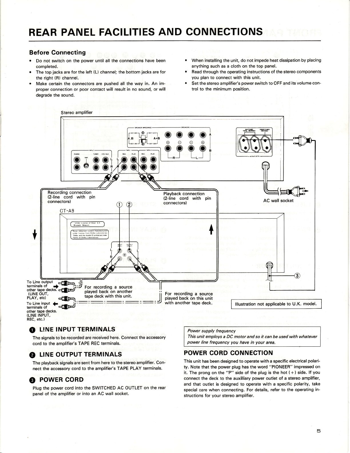
REAR
PANEL
FACILITIES
AND CONNECTIONS
Before
.
Gonnecting
not switch on the
Do
completed.
jacks
top
The
the right
Make certain the connectors are
proper
degrade the
are
(R)
channel.
connection or
sound.
Stereo
Dower
for the left
poor
amplifier
@
T
@@@@t
Recording
(2-line
connectors,
connection_
with
cord
the
until all
(L)
channel;
contact will result in no sound,
'.'.""",.,I
pushed
connections
the
bottom
the way in. An
all
have been
jacks
@@+
pin
fi\ ra\
are for
im-
or will
playback
(2-line
connectors)
connection
cord with
installing
When
anything such
Read through the operating
you plan
the
Set
trol to the minimum
pin
the unit,
as a cloth
to connect with
stereo amplifier's
do not impede heat dissipation
on the top
this
power
position.
placing
panel.
instructions of the stereo components
unit.
switch to OFF and
by
its volume
con-
(LINE
INPUT,
etc.)
REC.
LINE TNPUT
o
The signals
cord
o
The
nect the accessory cord
o
Plug the
panel
to be recorded are
to the amplifier's
L|NE
OUTPUT
playback
signals are
PowER coRD
power
cord into the SWITCHED
the amplifier or
of
urdqrcD.dsbilsa
r
\-!s::-93::------
h-oobYks-b'.'
m@,,**.
I
odbYatuiMdo6eosFd'ekd
I
\::1:il9:lg.::::
I
TERMINALS
received
TAPE REC terminals.
TERMINALS
sent from here to
to the amplifier's
into an AC wall socket.
I
I
./
here.
Connect
the
TAPE PLAY
AC OUTLET
stereo
the accessory
amplifier. Con-
terminals.
on the rear
For recording
played
back
with
on this unit
another tape deck.
Power
This
power
POWER
This
ty.
Note that the
it.
The
connect the deck to the auxilliary
and that outlet is designed to operate
special
structions for
a source
lllustration
supply frequency
unit employs
line
a DC motor and so it can
frequency
you
have
CORD CONNECTION
has
unit
been designed
prong
care when connecting.
power plug
the
on
your
to operate with a specific
has the word
"P"
side of the
stereo amplifier.
not
applicable
your
in
area.
plug
power
outlet of a
with a specific
For details,
model.
to
U.K.
used with whatevel
be
"PIONEER"
electrical
is the hot ( + ) side.
stereo amplifier,
refer to the operating
polari-
impressed on
polariry,
lf
you
take
in-
5
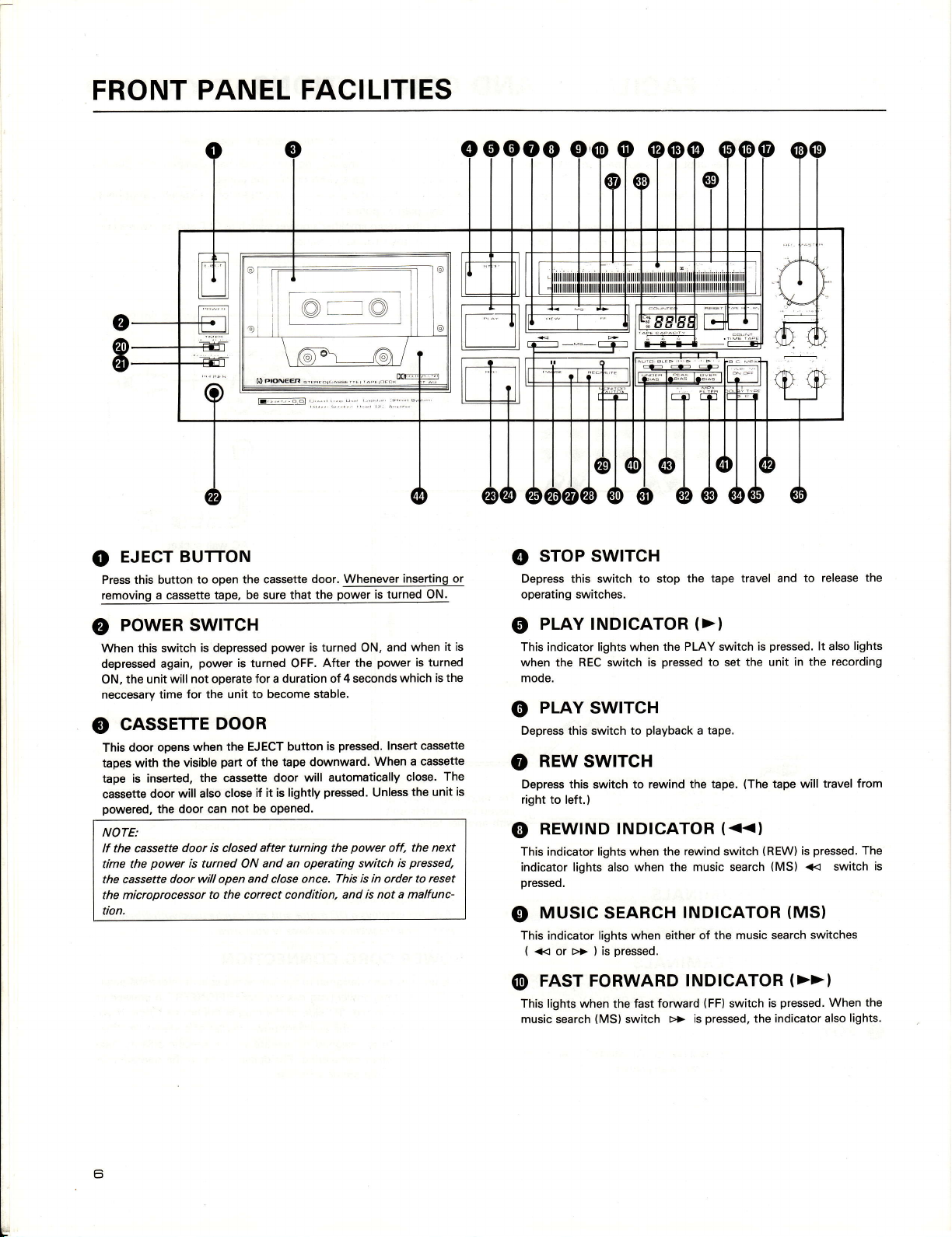
FRONT PANEL
FACILITIES
EJECT BUTTON
o
Press this button
removing
€)
When
depressed again,
ON,
neccesary time
o
This door
tapes with
tape is inserted,
cassette
powered,
NOTE:
lf the cassette
time the
the
the
tion.
a cassette tape.
POWER
this switch
the unit will
SWITCH
not
for
CASSETTE
when
opens
the visible
door will also
the door can
door is closed after turning the
power
is turned ON and an operating
cassette door
microprocessor
to open the cassette
be sure that the
is depressed
power
is
turned OFF.
for a duration of
operate
unit to become stable.
the
door. Whenever
power
is turned
After the
DOOR
the
EJECT
part
the tape downward.
of
the cassette
close
will
open
to the correct condition, and
door will automatically
if it is lightly
oPened.
not be
and close once. This
button
is
pressed.
power
is turned ON.
and
ON.
power
4 seconds
pressed.
Insert cassette
When
Unless
power
switch is
is in
order
is not a malfunc-
inserting or
when
is
which is
a cassette
close.
the
the next
off,
pressed,
to reset
it is
turned
the
The
unit
sToP swrTcH
@
lights
lt also
recording
travel from
The
When the
lights.
the
Depress this switch to stop
operating switches.
PLAY TNDTCATOR
o
This indicator lights when
;:::.tn"
G)
Depress this switch to
o
is
Depress this switch to rewind
right to left.)
o
This indicator lights when the
I:::T:
€)
This indicator lights when either
(
@
This lights when
music search
REC switch is
PLAY
REW
REWTND
SWTTCH
SWTTCH
TNDTCATOR
lights also
when the music search
MUS|C SEARCH
>> ) is
pressed.
<<
or
FAST FORWARD
fast forward
the
(MS)
switch
the tape travel and
(>)
the PLAY switch
pressed
playback
to
tape.
a
the tape.
(<<)
rewind
TNDTCATOR
of the music search
TNDICATOR
(FF)
pressed,
>> is
the unit in the
set
(The
switch
switch
the
to release
pressed.
is
tape will
(REW)
is
(MS)
<< switch is
(MS)
(>>)
pressed.
is
indicator also
pressed.
switches
 Loading...