

Pilz PSSu E PD, PSSu E PD-T Operating Instructions Manual

PSSu E PD(-T)
} Decentralised system PSSuniversal I/O
Operating instructions 21304-EN-04

Preface
This document is a translation of the original document.
All rights to this documentation are reserved by Pilz GmbH & Co. KG. Copies may be made
for internal purposes. Suggestions and comments for improving this documentation will be
gratefully received.
Pilz®, PIT®, PMI®, PNOZ®, Primo®, PSEN®, PSS®, PVIS®, SafetyBUS p®,
SafetyEYE®, SafetyNET p®, the spirit of safety® are registered and protected trademarks
of Pilz GmbH & Co. KG in some countries.
SD means Secure Digital

Contents
Section 1 Introduction 5
1.1 Validity of documentation 5
1.1.1 Retaining the documentation 5
1.2 Definition of symbols 5
Section 2 Overview 7
2.1 Module structure 7
2.2 Module features 7
2.3 Front view 8
Section 3 Safety 10
3.1 Intended use 10
3.2 Safety regulations 11
3.2.1 Use of qualified personnel 11
3.2.2 Warranty and liability 11
3.2.3 Disposal 11
Section 4 Function description 12
4.1 Block diagram 12
4.2 Module features 12
4.2.1 Functions 12
4.3 Configuration 12
4.3.1 Addresses in the process image 12
Section 5 Installation 13
5.1 General installation guidelines 13
5.1.1 Dimensions 13
5.2 Installing the base module 14
5.3 Inserting and removing an electronic module 15
5.3.1 Inserting an electronic module 16
5.3.2 Removing an electronic module 17
5.3.3 Changing an electronic module during operation 17
Section 6 Wiring 18
6.1 General wiring guidelines 18
6.1.1 Mechanical connection of the base modules 18
6.2 Terminal configuration 20
Section 7 Operation 22
7.1 Messages 22
7.2 Display elements 22
7.2.1 Display elements for module diagnostics 22
Section 8 Technical details 23
Operating instructions PSSu E PD(-T)
21304-EN-04
3

Contents
Section 9 Order reference 25
9.1 Product 25
9.2 Accessories 25
Operating instructions PSSu E PD(-T)
21304-EN-04
4
Introduction
1 Introduction
1.1 Validity of documentation
This documentation is valid for the products PSSu E PD and PSSu E PD-T. It is valid until
new documentation is published.
The module PSSu E PD-T is suitable for use where there are increased environmental requirements (see Technical Details).
This operating manual explains the function and operation, describes the installation and
provides guidelines on how to connect the product.
1.1.1 Retaining the documentation
This documentation is intended for instruction and should be retained for future reference.
1.2 Definition of symbols
Information that is particularly important is identified as follows:
DANGER!
This warning must be heeded! It warns of a hazardous situation that poses
an immediate threat of serious injury and death and indicates preventive
measures that can be taken.
WARNING!
This warning must be heeded! It warns of a hazardous situation that could
lead to serious injury and death and indicates preventive measures that can
be taken.
CAUTION!
This refers to a hazard that can lead to a less serious or minor injury plus
material damage, and also provides information on preventive measures
that can be taken.
Operating instructions PSSu E PD(-T)
21304-EN-04
NOTICE
This describes a situation in which the product or devices could be damaged and also provides information on preventive measures that can be
taken. It also highlights areas within the text that are of particular importance.
5

Introduction
INFORMATION
This gives advice on applications and provides information on special features.
Operating instructions PSSu E PD(-T)
21304-EN-04
6

Overview
2 Overview
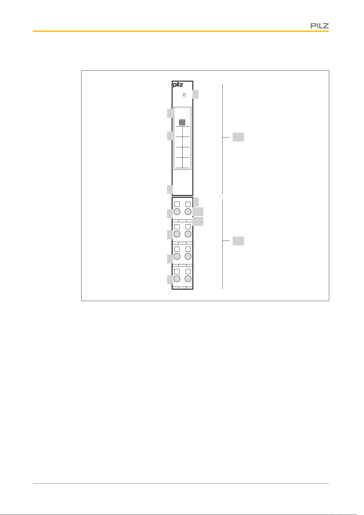
2.1 Module structure
A module consists of
} Electronic module and
} Base module with
– Screw terminals or
– Cage clamp terminals
The base modules are the carrier units for the electronic modules and are used to connect
the field wiring. The electronic modules are inserted on to the base modules and determine
the module's function.
Details of the base modules that can be used are available in the chapter entitled “Intended
Use”.
2.2 Module features
The product has the following features:
} The module routes the periphery supply from the module bus to the base module ter-
minals.
} LED for:
– Periphery supply
} Application range depends on the base module
} T-type:
PSSu E PD-T: for increased environmental requirements
Operating instructions PSSu E PD(-T)
21304-EN-04
7
Overview
2111
2212
2313
2414
110V21
0V
120V22
0V
13
(C)23(C)
14 24
PSSu E
PD
24V
24V 24V
PSSu E
PD
312195
000000
001
1
3
8
7
4
5
6
10
2
11
9
A
B
2.3 Front view
Key:
} A: Electronic module
} B: Base module
} 1: LED for module diagnostics
} 2: Labelling strip with:
} 3: Labelling strip for the terminal configuration on the base module
Operating instructions PSSu E PD(-T)
21304-EN-04
} 4: Name of electronic module
} 5: Connection level 1
} 6: Connection level 2
} 7: Connection level 3
} 8: Connection level 4
– Name of electronic module
– Order number
– Serial number
– Hardware version number
– 2D code
8
 Loading...