

Page 1

Operating Manual PSSu E PD1(-T)
Operating Manual PSSu E PD1(-T)
PSSu E PD1(-T)
Decentralised system PSSuniversal I/O
Operating Manual — No. 21453-EN-03
Page 2

This document is a translation of the original document.
All rights to this documentation are reserved by Pilz GmbH & Co. KG. Copies may be made
for internal purposes.
Suggestions and comments for improving this documentation will be gratefully received.
Pilz®, PIT®, PMI®, PNOZ®, Primo®, PSEN®, PSS®, PVIS®, SafetyBUS p®, SafetyEYE®,
SafetyNET p®, the spirit of safety® are registered and protected trademarks of
Pilz GmbH & Co. KG in some countries.
SD means Secure Digital.
Preface
Page 3

Contents
Contents
Contents Page
Chapter 1 Introduction
1.1 Validity of documentation 1-1
1.1.1 Retaining the documentation 1-1
1.2 Overview of documentation 1-2
1.3 Definition of symbols 1-3
Chapter 2 Overview
2.1 Module structure 2-1
2.1.1 Module features 2-1
2.2 Front view 2-2
Chapter 3 Safety
3.1 Intended Use 3-1
3.2 Safety regulations 3-2
3.2.1 Use of qualified personnel 3-2
3.2.2 Warranty and liability 3-2
3.2.3 Disposal 3-2
Chapter 4 Function description
4.1 Module features 4-1
4.1.1 Function description 4-1
4.2 Configuration 4-2
4.2.1 Configuration 4-2
4.2.2 Addresses in the process image 4-2
Chapter 5 Installation
5.1 General installation guidelines 5-1
5.1.1 Dimensions 5-1
5.2 Installing the base module 5-2
5.3 Inserting and removing an electronic
module
5.3.1 Inserting an electronic module 5-3
5.3.2 Removing an electronic module 5-4
Chapter 6 Wiring
6.1 General wiring guidelines 6-1
6.1.1 Mechanical connection of the base
modules
6.2 Terminal configuration 6-4
5-3
6-1
Chapter 7 Operation
7.1 Messages and display elements 7-1
Pilz GmbH & Co. KG, Felix-Wankel-Straße 2, 73760 Ostfildern, Germany
Telephone: +49 711 3409-0, Telefax: +49 711 3409-133, E-Mail: pilz.gmbh@pilz.de
1
Page 4

Contents
Chapter 8 Technical details
8.1 Technical details 8-1
8.2 Order reference 8-3
Pilz GmbH & Co. KG, Felix-Wankel-Straße 2, 73760 Ostfildern, Germany
2
Telephone: +49 711 3409-0, Telefax: +49 711 3409-133, E-Mail: pilz.gmbh@pilz.de
Page 5

1 Introduction
1.1 Validity of documentation
11000IntroductionIntroduction1-1.1Validity of docume ntation1100Validity of documenta tion1-][BA Einf Gültigkeit_(T)
This documentation is valid for the products PSSu E PD1 and
Einf Einleitung
1.1.1 Retaining the documentation
Retaining the documentation1-Einf Aufbewahren
PSSu E PD1-T. It is valid until new documentation is published.
This operating manual explains the function and operation, describes
the installation and provides guidelines on how to connect the product .
This documentation is intended for instruction and should be retained
for future reference.
Pilz GmbH & Co. KG, Felix-Wankel-Straße 2, 73760 Ostfildern, Germany
Telephone: +49 711 3409-0, Telefax: +49 711 3409-133, E-Mail: pilz.gmbh@pilz.de
1-1
Page 6

1 Introduction
1.2 Overview of documentation
1.2Overview of documentation1200Overview of documentation1-][BA Einf Übersicht E-Modul
1 Introduction
The introduction is designed to familiarise you with the contents, structure and specific order of this manual.
2 Overview
This chapter provides information on the product's most important features.
3 Safety
This chapter must be read as it contains important information on safety
and intended use.
4 Function Description
This chapter describes the product's individual components.
5 Installation
This chapter explains how to install the product.
6 Wiring
This chapter describes the product's wiring.
7 Operation
This chapter explains the display elements and advises on what to do if
a fault occurs.
8 Technical Details
This chapter contains the product's technical details and order reference.
1-2
Pilz GmbH & Co. KG, Felix-Wankel-Straße 2, 73760 Ostfildern, Germany
Telephone: +49 711 3409-0, Telefax: +49 711 3409-133, E-Mail: pilz.gmbh@pilz.de
Page 7
1 Introduction
1.3 Definition of symbols
1.3Definition of symbols1300Definition of symbols1-Einfhrung Zeichen
Information that is particularly important is identified as follows:
DANGER!
This warning must be heeded! It warns of a hazardous situation
that poses an immediate threat of serious injury and death and
indicates preventive measures that can be taken.
WARNING!
This warning must be heeded! It warns of a hazardous situation
that could lead to serious injury and death and indicates preventive measures that can be taken.
CAUTION!
This refers to a hazard that can lead to a less serious or minor
injury plus material damage, and also provides information on
preventive measures that can be taken.
NOTICE
This describes a situation in which the product or devices could
be damaged and also provides information on preventive measures that can be taken.
INFORMATION
This gives advice on applications and provides information on
special features, as well as highlighting areas within the text that
are of particular importance.
Pilz GmbH & Co. KG, Felix-Wankel-Straße 2, 73760 Ostfildern, Germany
Telephone: +49 711 3409-0, Telefax: +49 711 3409-133, E-Mail: pilz.gmbh@pilz.de
1-3
Page 8

1 Introduction
1-4
Pilz GmbH & Co. KG, Felix-Wankel-Straße 2, 73760 Ostfildern, Germany
Telephone: +49 711 3409-0, Telefax: +49 711 3409-133, E-Mail: pilz.gmbh@pilz.de
Page 9

2 Overview
2.1 Module structure
22000OverviewOverview2-2.1Module structure2100Module structure2-][BA bersic ht Aufbau
A module consists of
Electronic module and
Base module with
The base modules are the carrier units for the electronic modules and
are used to connect the field wiring. The electronic modules are inserted
on to the base modules and determine the module's function.
Details of the base modules that can be used are available in the chapter
entitled “Intended Use”.
– Screw terminals or
– Cage clamp terminals
2.1.1 Module features
Module features2-][Merkmale_Versorgung PD1
][Geraetemerkmal_T
The module provides connections for external supplies.
The external supplies are galvanically isolated from the module bus
supplies.
Coated version of the module:
PSSu E PD1-T: for increased environmental requirements
Pilz GmbH & Co. KG, Felix-Wankel-Straße 2, 73760 Ostfildern, Germany
Telephone: +49 711 3409-0, Telefax: +49 711 3409-133, E-Mail: pilz.gmbh@pilz.de
2-1
Page 10
2 Overview
2111
2212
2414
4131
4232
4434
PSSu E
PD1
2313 4333
12
P2
11
P1
13
P3
14
P4
22
P2
21
P1
23
P3
24
P4
32
P2
31
P1
33
P3
34
P4
42
P2
41
P1
43
P3
44
P4
PSSu E
PD1
312196
000000
001
10
1
3
4
9
8
5
6
7
2
A
B
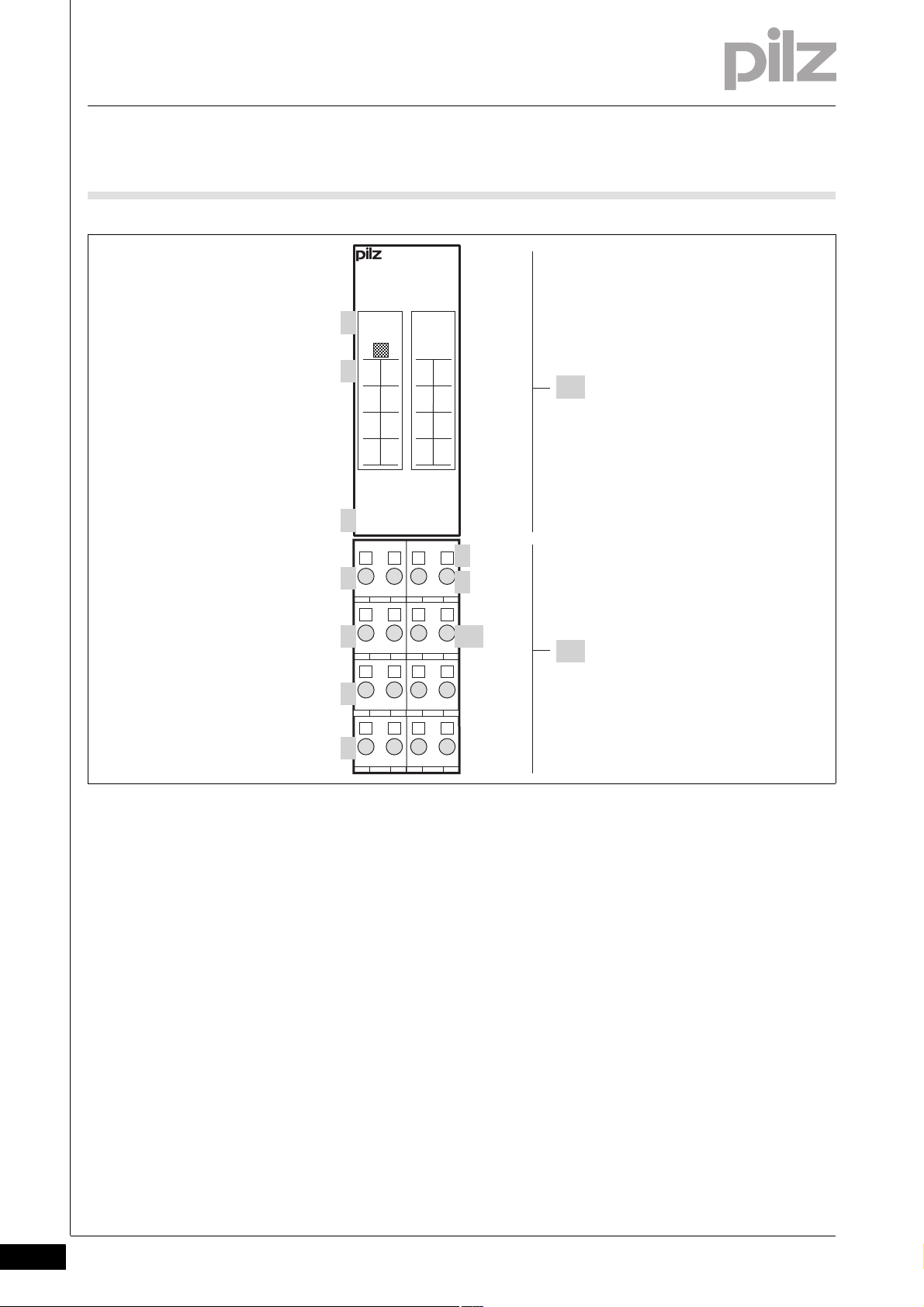
2.2 Front view
2.2Front view2200Front view2-BA_Fron tansicht
2-2
][BA_Frontansicht Legende ohne LED
Key:
A: Electronic module:
PSSu E PD1
PSSu E PD1-T
B: Base module
1: Labelling strip with:
– Name of electronic module
– Order number
– Serial number
– Hardware version number
–2D code
2: Labelling strip for the terminal configuration on the base module
Pilz GmbH & Co. KG, Felix-Wankel-Straße 2, 73760 Ostfildern, Germany
Telephone: +49 711 3409-0, Telefax: +49 711 3409-133, E-Mail: pilz.gmbh@pilz.de
3: Name of electronic module
4: Connection level 1
5: Connection level 2
6: Connection level 3
7: Connection level 4
Page 11

2 Overview
2.2 Front view
8: Square mounting holes (connection levels 1, 2, 3 and 4)
– With screw to loosen/tighten the screw terminal on base modules
with screw terminals
– With mechanism to operate the cage clamp on base modules with
cage clamp terminals
9: Round connection holes (connection levels 1, 2, 3 and 4) for con-
necting the signal lines
10: Mounting slot for colour marker to label the connection level (con-
nection levels 1, 2, 3 and 4)
Pilz GmbH & Co. KG, Felix-Wankel-Straße 2, 73760 Ostfildern, Germany
Telephone: +49 711 3409-0, Telefax: +49 711 3409-133, E-Mail: pilz.gmbh@pilz.de
2-3
Page 12

2 Overview
2-4
Pilz GmbH & Co. KG, Felix-Wankel-Straße 2, 73760 Ostfildern, Germany
Telephone: +49 711 3409-0, Telefax: +49 711 3409-133, E-Mail: pilz.gmbh@pilz.de
Page 13

3 Safety
3.1 Intended Use
33000SafetySafety3-3.1Intended Use3100Intended U se3-][Gertebeschreibung PD1
Bestimm_Verwend_ Zusatz-(T)
Bestimmung/Gertebeschreibung_Ausschluss
Bestimm_Verwend_Info_PSSu_ab_1.4.0_PAS4000_ab_1.1.1
The module may be used to feed and extract external supplies to and
from the connection terminals.
The module PSSu E PD1-T is suitable for use where there are increased
environmental requirements (see Technical Details).
Intended use includes making the electrical installation EMC-compliant.
Please refer to the guidelines stated in the "PSSuniversal Installation
Manual". The module is designed for use in an industrial environment. It
is not suitable for use in a domestic environment, as this can lead to interference.
The following is deemed improper use in particular:
Any component, technical or electrical modification to the module
Use of the module outside the areas described in this manual
Use of the module outside the technical details (see chapter entitled
"Technical Details")
Bestimm_Verwend_B asismodule
][BA_Basismodule Digital breit
][BA_Basismodule Digital(-T) breit
INFORMATION
The module is supported by
PSSuniversal Configurator and PSSuniversal Assistant from
Version 1.4.0
PAS4000 from Version 1.1.1
– We recommend that you always use the latest version
(download from www.pilz.de).
The PSSu E PD1 module may be used in conjunction with the following
base modules:
PSSu BP 2/16S
PSSu BP 2/16C
PSSu BP-C 2/16S
PSSu BP-C 2/16C
The PSSu E PD1-T module may be used in conjunction with the following base modules:
PSSu BP 2/16S-T
PSSu BP 2/16C-T
PSSu BP-C 2/16S-T
PSSu BP-C 2/16C-T
Pilz GmbH & Co. KG, Felix-Wankel-Straße 2, 73760 Ostfildern, Germany
Telephone: +49 711 3409-0, Telefax: +49 711 3409-133, E-Mail: pilz.gmbh@pilz.de
3-1
Page 14

3 Safety
3.2 Safety regulations
3.2Safety regulations3200Safety regulation s3-
3.2.1 Use of qualified personnel
Use of qualified personnel3-Sich Qualif. Personal
The products may only be assembled, installed, programmed, commissioned, operated, maintained and decommissioned by competent persons.
A competent person is someone who, because of their training, experience and current professional activity, has the specialist knowledge required to test, assess and operate the work equipment, devices,
systems, plant and machinery in accordance with the general standards
and guidelines for safety technology.
It is the company's responsibility only to employ personnel who:
Are familiar with the basic regulations concerning health and safety /
accident prevention
Have read and understood the safety guidelines given in this descrip-
tion
Have a good knowledge of the generic and specialist standards ap-
plicable to the specific application.
3.2.2 Warranty and liability
Warranty and liability3-Sich Gewhrleistung
3.2.3 Disposal
Disposal3-Si ch Entsorgung
All claims to warranty and liability will be rendered invalid if:
The product was used contrary to the purpose for which it is intended
Damage can be attributed to not having followed the guidelines in the
manual
Operating personnel are not suitably qualified
Any type of modification has been made (e.g. exchanging compo-
nents on the PCB boards, soldering work etc.).
In safety-related applications, please comply with the mission time t
M
in the safety-related characteristic data.
When decommissioning, please comply with local regulations regard-
ing the disposal of electronic devices (e.g. Electrical and Electronic
Equipment Act).
3-2
Pilz GmbH & Co. KG, Felix-Wankel-Straße 2, 73760 Ostfildern, Germany
Telephone: +49 711 3409-0, Telefax: +49 711 3409-133, E-Mail: pilz.gmbh@pilz.de
Page 15

4 Function description
4.1 Module features
44000Function descriptionFunction description4-4.1Module features4100Module features4-
4.1.1 Function description
Function description4-][Funktionsbeschreibung PD1
Module supply
The module needs no supply from the module supply.
Periphery supply
The module distributes the periphery supply on the module bus.
The periphery supply is not available on the module's connection ter-
minals.
External supplies
The module provides connections for external supplies.
The module does not switch the external supplies.
The external supplies are galvanically isolated from the module bus
supplies and from each other.
The module has no current limitation on the external supplies.
Pilz GmbH & Co. KG, Felix-Wankel-Straße 2, 73760 Ostfildern, Germany
Telephone: +49 711 3409-0, Telefax: +49 711 3409-133, E-Mail: pilz.gmbh@pilz.de
4-1
Page 16

4 Function description
4.2 Configuration
4.2Configuration4200Configuration4-
4.2.1 Configuration
Configuration4-][Funktionsbeschreibung_BA_Konfig Keine Konfig
The module does not have to be configured.
4.2.2 Addresses in the process image
Addresses in the process image4-][Funktionsbeschreibung_BA_PA Keine Adresse
The module does not occupy any addresses in the process image.
4-2
Pilz GmbH & Co. KG, Felix-Wankel-Straße 2, 73760 Ostfildern, Germany
Telephone: +49 711 3409-0, Telefax: +49 711 3409-133, E-Mail: pilz.gmbh@pilz.de
Page 17

5 Installation
25,2 mm
76 mm
52,1 mm8,1 mm
67,7 mm
25,2 mm
56,1 mm 71,8 mm
0,8 mm
128,9 mm
72,7 mm
(2.862")
(2.992")
(2.209") (2.827")
(0.031")
5.075")
(0.992") (2.051")(0.319")
(0.992")
(2.665")
5.1 General installation guidelines
55000InstallationInstallation5-5.1General installation guidelines5100General installation guidelines5-][Montage BA E-Modul Allgemein
Montage_EMV ESD
5.1.1 Dimensions
Dimensions5-][Abmessungen 2xR
Please also refer to the PSSuniversal Installation Manual.
CAUTION!
Damage due to electrostatic discharge!
Electrostatic discharge can damage components. Ensure
against discharge before touching the product, e.g. by touching
an earthed, conductive surface or by wearing an earthed armband.
Pilz GmbH & Co. KG, Felix-Wankel-Straße 2, 73760 Ostfildern, Germany
Telephone: +49 711 3409-0, Telefax: +49 711 3409-133, E-Mail: pilz.gmbh@pilz.de
5-1
Page 18

5 Installation
[2]
[1]
[3]
5.2 Installing the base module
5.2Installing the base module5200Installing the base module5-][Montage Basismodul
Prerequisite:
The head module must be installed.
If the head module does not have an integrated power supply, a sup-
ply voltage module must be installed to the right of the head module.
Please note:
For mechanical reasons it is not possible to mix base modules with
screw terminals and base modules with cage clamp terminals.
All contacts should be protected from contamination.
The mechanics of the base modules are designed for 50 plug in/out
cycles.
Procedure:
We recommend that you wire up the base modules before inserting
the electronic modules.
Slot the groove on the base module on to the mounting rail from be-
low [1].
Push the base module back [2] until you hear it lock into position.
On the mounting rail, slide the base module to the left until you hear
the two lateral mounting hooks on the adjacent module lock into position [3].
Schematic representation:
5-2
Pilz GmbH & Co. KG, Felix-Wankel-Straße 2, 73760 Ostfildern, Germany
Telephone: +49 711 3409-0, Telefax: +49 711 3409-133, E-Mail: pilz.gmbh@pilz.de
Page 19

5 Installation
[2]
[1]
[1]
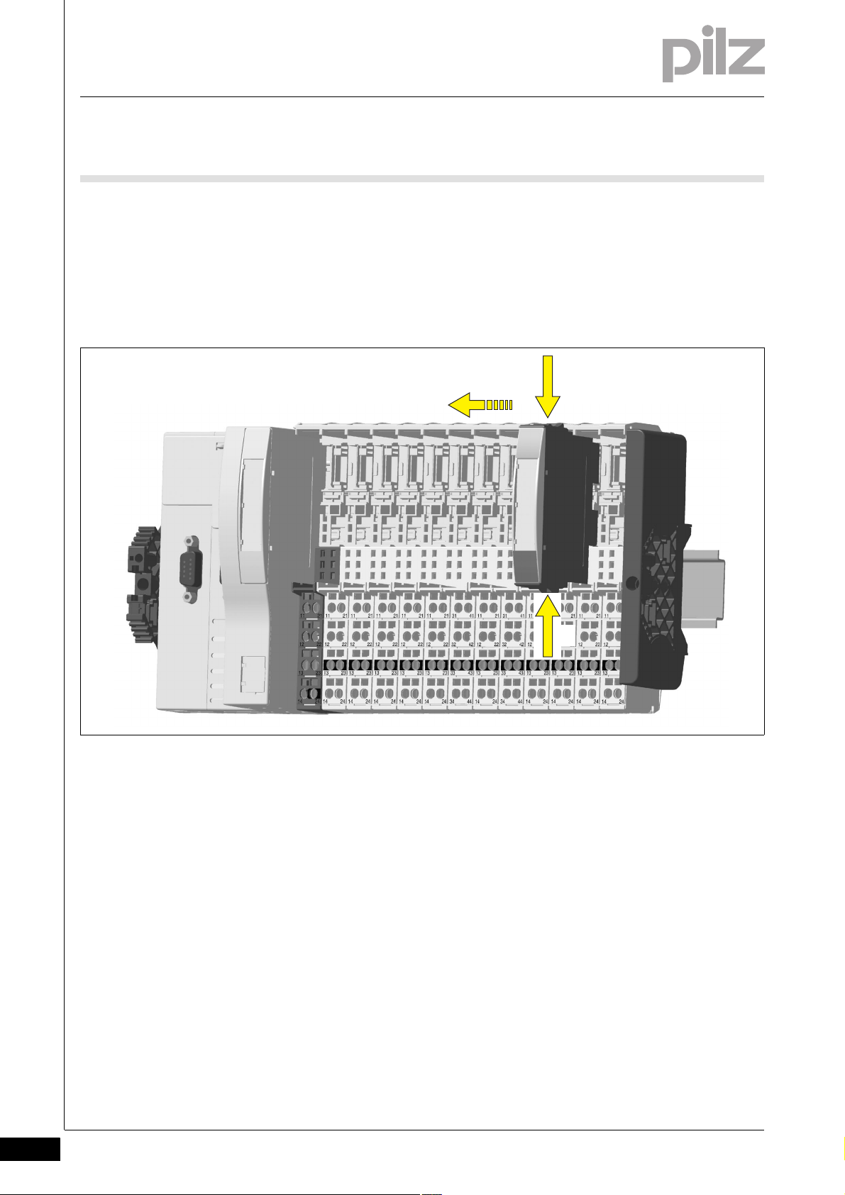
5.3 Inserting and removing an electronic module
5.3Inserting and removing an electronic module5300Inserting and removing an electronic module5-
5.3.1 Inserting an electronic module
Inserting an electronic module5-][Elektronikmodul stecken
Procedure:
The electronic module must audibly lock into position [1].
Mark the electronic module using the labelling strips [2].
Schematic representation:
][Elektronikmodul stecken und ziehen
Please note:
Only insert on to base modules that are already installed.
Preferably these base modules should be ready wired.
Electronic modules with outputs may only be inserted and removed
when the load is switched off. Unforeseeable error reactions may be
triggered if modules are inserted and removed under load.
When an electronic module is plugged into a base module for the first
time, one part of the coding element remains on the electronic module, while its counterpart is fixed on to the base module. This is how
the base module is coded.
The mechanics of the electronic modules are designed for 50 plug in/
out cycles.
Pilz GmbH & Co. KG, Felix-Wankel-Straße 2, 73760 Ostfildern, Germany
Telephone: +49 711 3409-0, Telefax: +49 711 3409-133, E-Mail: pilz.gmbh@pilz.de
5-3
Page 20
5 Installation
[1]
[2]
[1]
5.3 Inserting and removing an electronic module
5.3.2 Removing an electronic module
Removing an electronic module5-][Elektronikmodul ziehen
Procedure:
Press the locking mechanisms [1] together simultaneously.
Pull out the electronic module [2].
Schematic representation:
5-4
Pilz GmbH & Co. KG, Felix-Wankel-Straße 2, 73760 Ostfildern, Germany
Telephone: +49 711 3409-0, Telefax: +49 711 3409-133, E-Mail: pilz.gmbh@pilz.de
Page 21

6 Wiring
DIN 5264-A
6.1 General wiring guidelines
66000WiringWiring6-6.1General wiring gu idelines6100Gene ral wiring guideline s6-][Verdrahtung BA Einleitung
][Verdrahtung PD1
Safe electrical isolation must be ensured for the external supplies.
Failure to do so could result in electric shock.
Please note:
The external power supplies must comply with the current applicable
standard EN 60950-1, EN 61140, EN 50178 or EN 61558-1.
The maximum current load on the connection terminals is 4 A per
supply.
Permitted infeed at the module's connection terminals:
–PE
–0V
–Shield
– - 30 VDC ... + 30 VDC
– - 48 VAC ... + 48 VAC
][Verdrahtung Zusatz ohne C
Use copper wiring.
The terminal configuration as stated on the front plate applies for base
modules without C-rail. The terminal configuration as stated in the
technical documentation applies for all other base modules.
6.1.1 Mechanical connection of the base modules
Mechanical connection of the base modules6-][Modulverdrahtung mech
Procedure:
Use a flat blade screwdriver (DIN 5264-A)!
Strip the wire back 8 mm.
If necessary, label the connection level with a colour marker [3].
Base module with screw terminals:
– Use a screwdriver to loosen the screw on the screw terminal [1]
– Insert the stripped cable into the round fixing hole [2], as far as it
will go.
– Tighten up the screw on the screw terminal.
– Check that the cable is firmly seated.
Pilz GmbH & Co. KG, Felix-Wankel-Straße 2, 73760 Ostfildern, Germany
Telephone: +49 711 3409-0, Telefax: +49 711 3409-133, E-Mail: pilz.gmbh@pilz.de
6-1
Page 22

6 Wiring
2111
[1]
[3]
[2]
[4]
[5]
[6]
6.1 General wiring guidelines
Base module with cage clamp terminals:
– Insert the screwdriver [4] into the square hole [1].
– Insert the stripped cable into the round fixing hole [2], as far as it
will go [5].
– Pull out the screwdriver [6].
– Check that the cable is firmly seated.
][Modulverdrahtung el Sys A + B
Please note:
The minimum cable cross section for field connection terminals on the
2
base modules is 0.14 mm
The maximum cable cross section for field connection terminals is:
– Digital inputs: 1.5 mm
– Digital outputs: 2.0 mm
– Inputs/outputs on the counter modules: 1.5 mm
– Analogue inputs/outputs: 1.5 mm
– Communication cables: 1.5 mm
– Test pulse outputs: 1.5 mm
– Power supply: 2.5 mm
– Functional earth: 2.5 mm
(AWG26)
2
(AWG16)
2
(AWG14)
2
(AWG16)
2
(AWG12)
2
(AWG12)
2
(AWG16)
2
(AWG16)
2
(AWG16)
6-2
Pilz GmbH & Co. KG, Felix-Wankel-Straße 2, 73760 Ostfildern, Germany
Telephone: +49 711 3409-0, Telefax: +49 711 3409-133, E-Mail: pilz.gmbh@pilz.de
Page 23

6 Wiring
6.1 General wiring guidelines
On base modules with screw terminals:
– If you use a multi-strand cable to connect the I/Os, it is recom-
mended that you use ferrules conforming to Parts 1 and 2 of DIN
46228, 0.14 ... 1.5 mm
To crimp the ferrules you can use crimp pliers (crimp form A or C)
conforming to EN 60947-1, such as the PZ 1.5 or PZ 6.5 from
Weidmüller, for example.
– Maximum torque setting: 0.8 Nm
Use copper wiring.
2
, Form A or C, although this is not essential.
Pilz GmbH & Co. KG, Felix-Wankel-Straße 2, 73760 Ostfildern, Germany
Telephone: +49 711 3409-0, Telefax: +49 711 3409-133, E-Mail: pilz.gmbh@pilz.de
6-3
Page 24

6 Wiring
2111
2212
2313
2414
4131
4232
4333
4434
2111
2212
2313
2414
4131
4232
4333
4434
6.2 Terminal configuration
6.2Terminal configuration6200Terminal configuration6-][Klemmenbelegung PD1
Base module Terminal configuration
Screw terminals:
PSSu BP 2/16S
PSSu BP 2/16S-T
11-21-31-41:
Supply P1
(11-21-31-41 linked internally)
Cage clamp terminals:
PSSu BP 2/16C
PSSu BP 2/16C-T
Screw terminals:
PSSu BP-C 2/16S
PSSu BP-C 2/16S-T
Cage clamp terminals:
PSSu BP-C 2/16C
PSSu BP-C 2/16C-T
12-22-32-42:
Supply P2
(12-22-32-42 linked within the base
module)
13-23-33-43:
Supply P3
(13-23-33-43 linked within the base
module)
14-24-34-44:
Supply P4
(14-24-34-44 linked internally)
11-21-31-41:
Supply P1
(11-21-31-41 linked internally)
12-22-32-42:
Supply P2
(12-22-32-42 linked within the base
module)
13-23-33-43:
C-rail supply
(13-23-33-43 linked within the base
module)
14-24-34-44:
Supply P4
(14-24-34-44 linked internally)
6-4
Pilz GmbH & Co. KG, Felix-Wankel-Straße 2, 73760 Ostfildern, Germany
Telephone: +49 711 3409-0, Telefax: +49 711 3409-133, E-Mail: pilz.gmbh@pilz.de
Page 25

7 Operation
7.1 Messages and display elements
77000OperationOperation7-7.1Messages and display elements7100Messages and display elements7-][BA_B etrieb PD1
The module provides no diagnostic data and has no display elements.
Pilz GmbH & Co. KG, Felix-Wankel-Straße 2, 73760 Ostfildern, Germany
Telephone: +49 711 3409-0, Telefax: +49 711 3409-133, E-Mail: pilz.gmbh@pilz.de
7-1
Page 26

7 Operation
7-2
Pilz GmbH & Co. KG, Felix-Wankel-Straße 2, 73760 Ostfildern, Germany
Telephone: +49 711 3409-0, Telefax: +49 711 3409-133, E-Mail: pilz.gmbh@pilz.de
Page 27

8 Technical details
8.1 Technical details
88000Technical detailsTechnical details8-8.1Technical details8100Technical details8-][Technische Daten PSSu Spannungsverteilung
Technical details
Application range Standard
Support in system environment A
from FS firmware version for other head modules 1
from ST firmware version for other head modules 1
from FS firmware version PSSu H F PN 1
from ST firmware version PSSu H S PN 1
from ST firmware version PSSu WR S IDN 1
Support in system environment B
from head module FS firmware version 1.0.0
from head module ST firmware version 1.0.0
Electrical data
Max. power dissipation of the module 0.60 W
Environmental data
Ambient temperature in accordance with EN 60068-2-14 0 - 60 °C
-40 - 70 °C coated version (-T)
Storage temperature in accordance with EN 60068-2-1/-2 -25 - 70 °C
-40 - 70 °C coated version (-T)
Climatic suitability EN 60068-2-14, EN 60068-2-1, EN 60068-2-2,
EN 60068-2-30, EN 60068-2-78
Climatic suitability in accordance with EN 60068-2-30,
EN 60068-2-78
Condensation no
Max. operating height above sea level 5000 m coated version (-T)
EMC EN 61000-4-2, EN 61000-4-3, EN 61000-4-4,
Vibration to EN 60068-2-6
Frequency 10 - 150 Hz
Max. acceleration 1g
Shock stress
EN 60068-2-27 15g
EN 60068-2-29 10g
Protection type in accordance with EN 60529
Mounting (e.g. cabinet) IP54
Housing IP20
Terminals IP20
Airgap creepage in accordance with EN 60664-1
Overvoltage category II
Pollution degree 2
Mechanical data
Housing material
Front PC
Bottom PC
Coding PA
93 % r. h. at 40 °C
yes coated version (-T)
EN 61000-4-5, EN 61000-4-6, EN 61000-6-2,
EN 61000-6-4
11 ms
16 ms
Pilz GmbH & Co. KG, Felix-Wankel-Straße 2, 73760 Ostfildern, Germany
Telephone: +49 711 3409-0, Telefax: +49 711 3409-133, E-Mail: pilz.gmbh@pilz.de
8-1
Page 28

8 Technical details
8.1 Technical details
Mechanical data
Dimensions
Height 76.0 mm
Width 25.4 mm
Depth 60.2 mm
Weight 49 g
Mechanical coding
Type A
Colour light grey
Technische Daten_Satz No rmen
The standards current on 2005-04 apply.
8-2
Pilz GmbH & Co. KG, Felix-Wankel-Straße 2, 73760 Ostfildern, Germany
Telephone: +49 711 3409-0, Telefax: +49 711 3409-133, E-Mail: pilz.gmbh@pilz.de
Page 29
8 Technical details
8.2 Order reference
8.2Order reference8200Order reference8-Bestel ldaten
Order reference
Description Order no.
PSSu E PD1
(Electronic module)
PSSu E PD1-T
(Electronic module, coated version)
][Bestelldaten Basismodule Digital breit mit -T
Base modules Order no.
PSSu BP 2/16S
(Base module without C-rail with screw terminals)
PSSu BP 2/16S-T
(Base module without C-rail with screw terminals, coated
version)
PSSu BP 2/16C
(Base module without C-rail with cage clamp terminals)
PSSu BP 2/16C-T
(Base module without C-rail with cage clamp terminals,
coated version)
PSSu BP-C 2/16S
(Base module with C-rail and screw terminals)
PSSu BP-C 2/16S-T
(Base module with C-rail and screw terminals, coated version)
PSSu BP-C 2/16C
(Base module with C-rail and cage clamp terminals)
PSSu BP-C 2/16C-T
(Base module with C-rail and cage clamp terminals, coated
version)
312 196
314 196
312 628
314 628
312 629
314 629
312 630
314 630
312 631
314 631
Pilz GmbH & Co. KG, Felix-Wankel-Straße 2, 73760 Ostfildern, Germany
Telephone: +49 711 3409-0, Telefax: +49 711 3409-133, E-Mail: pilz.gmbh@pilz.de
8-3
Page 30

8 Technical details
8-4
Pilz GmbH & Co. KG, Felix-Wankel-Straße 2, 73760 Ostfildern, Germany
Telephone: +49 711 3409-0, Telefax: +49 711 3409-133, E-Mail: pilz.gmbh@pilz.de
Page 31

...
21453-EN-03, 2011-04 Printed in Germany
© Pilz GmbH & Co. KG, 2011
+49 711 3409-444
support@pilz.com
Pilz GmbH & Co. KG
Felix-Wankel-Straße 2
73760 Ostfildern, Germany
Telephone: +49 711 3409-0
Telefax: +49 711 3409-133
E-Mail: pilz.gmbh@pilz.de
Internet: www.pilz.com
Technical support
In many countries we are
represented by our subsidiaries
and sales partners.
Please refer to our homepage
for further details or contact our
headquarters.
InduraNET p
®
, Pilz
®
, PIT
®
, PMCprotego
®
, PMI
®
, PNOZ
®
, Primo
®
, PSEN
®
, PSS
®
, PVIS
®
, SafetyBUS p
®
, SafetyEYE
®
, SafetyNET p
®
, the spirit of safety
®
are registered and protected trademarks
of Pilz GmbH & Co. KG in some countries. We would point out that product features may vary from the details stated in this document, depending on the status at the time of publication and the scope
of the equipment. We accept no responsibility for the validity, accuracy and entirety of the text and graphics presented in this information. Please contact our Technical Support if you have any questions.
Contact address
 Loading...