

Page 1

Operating Manual PSSu E F PS(-T)
Operating Manual PSSu E F PS(-T)
PSSu E F PS(-T)
Decentralised system PSSuniversal I/O
Operating Manual — No. 21292-EN-04
Page 2

This document is a translation of the original document.
All rights to this documentation are reserved by Pilz GmbH & Co. KG. Copies may be made
for internal purposes.
Suggestions and comments for improving this documentation will be gratefully received.
Pilz®, PIT®, PMI®, PNOZ®, Primo®, PSEN®, PSS®, PVIS®, SafetyBUS p®, SafetyEYE®,
SafetyNET p®, the spirit of safety® are registered and protected trademarks of
Pilz GmbH & Co. KG in some countries.
SD means Secure Digital.
Preface
Page 3
Contents
Contents
Contents Page
Chapter 1 Introduction
1.1 Validity of documentation 1-1
1.1.1 Retaining the documentation 1-1
1.2 Overview of documentation 1-2
1.3 Definition of symbols 1-3
Chapter 2 Overview
2.1 Module structure 2-1
2.1.1 Module features 2-1
2.2 Front view 2-2
Chapter 3 Safety
3.1 Intended use 3-1
3.2 Safety regulations 3-3
3.2.1 Use of qualified personnel 3-3
3.2.2 Warranty and liability 3-3
3.2.3 Disposal 3-3
Chapter 4 Function description
4.1 Module features 4-1
4.1.1 Supply voltage 4-1
4.1.1.1 Current load capacity 4-2
4.1.2 Integrated protection mechanisms 4-4
4.2 Configuration 4-5
4.2.1 Application as a general supply module 4-5
4.2.1.1 Addresses in the process image 4-5
4.2.1.2 FS error behaviour 4-6
Chapter 5 Installation
5.1 General installation guidelines 5-1
5.1.1 Dimensions 5-1
5.2 Installing the base module 5-2
5.3 Inserting and removing an electronic
module
5.3.1 Inserting an electronic module 5-3
5.3.2 Removing an electronic module 5-4
5.3.3 Changing an electronic module during
operation
5-3
5-4
Pilz GmbH & Co. KG, Felix-Wankel-Straße 2, 73760 Ostfildern, Germany
Telephone: +49 711 3409-0, Telefax: +49 711 3409-133, E-Mail: pilz.gmbh@pilz.de
1
Page 4
Contents
Chapter 6 Wiring
6.1 General wiring guidelines 6-1
6.1.1 Mechanical connection of the base
6.2 Terminal configuration 6-4
6.3 Connecting the module 6-7
Chapter 7 Operation
7.1 Messages 7-1
7.2 Display elements 7-2
7.2.1 Anzeigeelemente zur Moduldiagnose 7-2
7.2.2 Display elements for the status of the
7.3 Status byte 7-4
6-1
modules
7-3
module supply and periphery supply
Chapter 8 Technical details
8.1 Technical details 8-1
8.2 Order reference 8-3
Pilz GmbH & Co. KG, Felix-Wankel-Straße 2, 73760 Ostfildern, Germany
2
Telephone: +49 711 3409-0, Telefax: +49 711 3409-133, E-Mail: pilz.gmbh@pilz.de
Page 5

1 Introduction
1.1 Validity of documentation
11000IntroductionIntroduction1-1.1Validity of docume ntation1100Validity of documenta tion1-][BA Einf Gültigkeit_(T)
This documentation is valid for the products PSSu E F PS and
Einf Einleitung
1.1.1 Retaining the documentation
Retaining the documentation1-Einf Aufbewahren
PSSu E F PS-T. It is valid until new documentation is published.
This operating manual explains the function and operation, describes
the installation and provides guidelines on how to connect the product .
This documentation is intended for instruction and should be retained
for future reference.
Pilz GmbH & Co. KG, Felix-Wankel-Straße 2, 73760 Ostfildern, Germany
Telephone: +49 711 3409-0, Telefax: +49 711 3409-133, E-Mail: pilz.gmbh@pilz.de
1-1
Page 6

1 Introduction
1.2 Overview of documentation
1.2Overview of documentation1200Overview of documentation1-][BA Einf Übersicht E-Modul
1 Introduction
The introduction is designed to familiarise you with the contents, structure and specific order of this manual.
2 Overview
This chapter provides information on the product's most important features.
3 Safety
This chapter must be read as it contains important information on safety
and intended use.
4 Function Description
This chapter describes the product's individual components.
5 Installation
This chapter explains how to install the product.
6 Wiring
This chapter describes the product's wiring.
7 Operation
This chapter explains the display elements and advises on what to do if
a fault occurs.
8 Technical Details
This chapter contains the product's technical details and order reference.
1-2
Pilz GmbH & Co. KG, Felix-Wankel-Straße 2, 73760 Ostfildern, Germany
Telephone: +49 711 3409-0, Telefax: +49 711 3409-133, E-Mail: pilz.gmbh@pilz.de
Page 7
1 Introduction
1.3 Definition of symbols
1.3Definition of symbols1300Definition of symbols1-Einfhrung Zeichen
Information that is particularly important is identified as follows:
DANGER!
This warning must be heeded! It warns of a hazardous situation
that poses an immediate threat of serious injury and death and
indicates preventive measures that can be taken.
WARNING!
This warning must be heeded! It warns of a hazardous situation
that could lead to serious injury and death and indicates preventive measures that can be taken.
CAUTION!
This refers to a hazard that can lead to a less serious or minor
injury plus material damage, and also provides information on
preventive measures that can be taken.
NOTICE
This describes a situation in which the product or devices could
be damaged and also provides information on preventive measures that can be taken.
INFORMATION
This gives advice on applications and provides information on
special features, as well as highlighting areas within the text that
are of particular importance.
Pilz GmbH & Co. KG, Felix-Wankel-Straße 2, 73760 Ostfildern, Germany
Telephone: +49 711 3409-0, Telefax: +49 711 3409-133, E-Mail: pilz.gmbh@pilz.de
1-3
Page 8

1 Introduction
1-4
Pilz GmbH & Co. KG, Felix-Wankel-Straße 2, 73760 Ostfildern, Germany
Telephone: +49 711 3409-0, Telefax: +49 711 3409-133, E-Mail: pilz.gmbh@pilz.de
Page 9

2 Overview
2.1 Module structure
22000OverviewOverview2-2.1Module structure2100Module structure2-][BA bersic ht Aufbau
A module consists of
Electronic module and
Base module with
The base modules are the carrier units for the electronic modules and
are used to connect the field wiring. The electronic modules are inserted
on to the base modules and determine the module's function.
Details of the base modules that can be used are available in the chapter
entitled “Intended Use”.
– Screw terminals or
– Cage clamp terminals
2.1.1 Module features
Module features2-][Merkmale_Versorgung PS
][Merkmale_LED PS
][Merkmale_Zusatz
][Geraetemerkmal_T
Power supply for max. 1.5 A
The module supply is not buffered if the supply voltage is interrupted
Separate infeed for periphery supply
Separate infeed for module supply
Infeed for C-rail supply
LEDs for:
–Module supply
– Periphery supply
– Module error
Application range depends on the base module
Coated version of the module:
PSSu E F PS-T: for increased environmental requirements
Pilz GmbH & Co. KG, Felix-Wankel-Straße 2, 73760 Ostfildern, Germany
Telephone: +49 711 3409-0, Telefax: +49 711 3409-133, E-Mail: pilz.gmbh@pilz.de
2-1
Page 10
2 Overview
2111
2212
2313
Err
11 21
120V22
0V
13 23
14C24
C
PSSu E F
P S
5 V 24 V
0V24V
24V 24V
2414
PSSu E F
PS
312190
000000
001
1
3
8
7
4
5
6
10
2
11
9
A
B
2.2 Front view
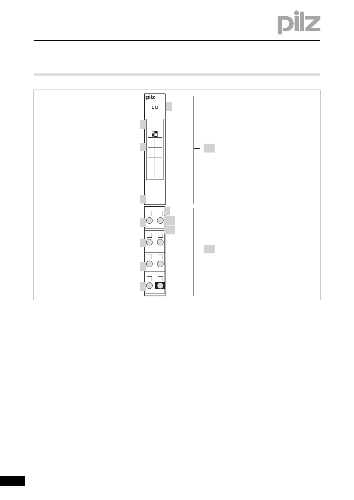
2.2Front view2200Front view2-BA Frontansicht
2-2
][BA_Frontansicht Legende Diag
Key:
A: Electronic module
B: Base module
1: LED for module diagnostics
2: Labelling strip with:
– Name of electronic module
– Order number
– Serial number
– Hardware version number
–2D code
3: Labelling strip for the terminal configuration on the base module
4: Name of electronic module
Pilz GmbH & Co. KG, Felix-Wankel-Straße 2, 73760 Ostfildern, Germany
Telephone: +49 711 3409-0, Telefax: +49 711 3409-133, E-Mail: pilz.gmbh@pilz.de
5: Connection level 1
6: Connection level 2
7: Connection level 3
8: Connection level 4
Page 11

2 Overview
2.2 Front view
9: Square mounting holes (connection levels 1, 2, 3 and 4)
– With screw to loosen/tighten the screw terminal on base modules
with screw terminals
– With mechanism to operate the cage clamp on base modules with
cage clamp terminals
10: Round connection holes (connection levels 1, 2, 3 and 4) for con-
necting the signal lines
11: Mounting slot for colour marker to label the connection level (con-
nection levels 1, 2, 3 and 4)
Pilz GmbH & Co. KG, Felix-Wankel-Straße 2, 73760 Ostfildern, Germany
Telephone: +49 711 3409-0, Telefax: +49 711 3409-133, E-Mail: pilz.gmbh@pilz.de
2-3
Page 12

2 Overview
2-4
Pilz GmbH & Co. KG, Felix-Wankel-Straße 2, 73760 Ostfildern, Germany
Telephone: +49 711 3409-0, Telefax: +49 711 3409-133, E-Mail: pilz.gmbh@pilz.de
Page 13
3 Safety
3.1 Intended use
33000SafetySafety3-3.1Intended use3100Intended use3-][Gertebeschreibung PS
Bestimm_Verwend_ Zusatz-(T)
Bestimmung/Gertebeschreibung_Ausschluss
The module provides the supply for the module supply and periphery
supply within the system.
Depending on which base module is used, the module may be used as
a:
General supply module (first module after a head module, if the head
module does not have an integrated supply voltage)
Supply module to refresh the module supply and periphery supply
Supply module to form supply groups
The module PSSu E F PS-T is suitable for use where there are increased
environmental requirements (see Technical Details).
Bestimm_Verwend_Info_PSSu_ab_1.4.0_PAS4000_ab_1.1.1
Intended use includes making the electrical installation EMC-compliant.
Please refer to the guidelines stated in the "PSSuniversal Installation
Manual". The module is designed for use in an industrial environment. It
is not suitable for use in a domestic environment, as this can lead to interference.
The following is deemed improper use in particular:
Any component, technical or electrical modification to the module
Use of the module outside the areas described in this manual
Use of the module outside the technical details (see chapter entitled
"Technical Details")
INFORMATION
The module is supported by
PSSuniversal Configurator and PSSuniversal Assistant from
Version 1.4.0
PAS4000 from Version 1.1.1
– We recommend that you always use the latest version
(download from www.pilz.de).
Bestimm_Verwend_B asismodule
Pilz GmbH & Co. KG, Felix-Wankel-Straße 2, 73760 Ostfildern, Germany
Telephone: +49 711 3409-0, Telefax: +49 711 3409-133, E-Mail: pilz.gmbh@pilz.de
3-1
Page 14

3 Safety
3.1 Intended use
][BA_Basismodule PS
][BA_Basismodule PS-T
The PSSu E F PS module may be used in conjunction with the following
base modules:
PSSu BS 1/8S
PSSu BS-R 1/8S
PSSu BS 1/8C
PSSu BS-R 1/8C
The PSSu E F PS-T module may be used in conjunction with the following base modules:
PSSu BS 1/8S-T
PSSu BS-R 1/8S-T
PSSu BS 1/8C-T
PSSu BS-R 1/8C-T
3-2
Pilz GmbH & Co. KG, Felix-Wankel-Straße 2, 73760 Ostfildern, Germany
Telephone: +49 711 3409-0, Telefax: +49 711 3409-133, E-Mail: pilz.gmbh@pilz.de
Page 15

3 Safety
3.2 Safety regulations
3.2Safety regulations3200Safety regulation s3-
3.2.1 Use of qualified personnel
Use of qualified personnel3-Sich Qualif. Personal
The products may only be assembled, installed, programmed, commissioned, operated, maintained and decommissioned by competent persons.
A competent person is someone who, because of their training, experience and current professional activity, has the specialist knowledge required to test, assess and operate the work equipment, devices,
systems, plant and machinery in accordance with the general standards
and guidelines for safety technology.
It is the company's responsibility only to employ personnel who:
Are familiar with the basic regulations concerning health and safety /
accident prevention
Have read and understood the safety guidelines given in this descrip-
tion
Have a good knowledge of the generic and specialist standards ap-
plicable to the specific application.
3.2.2 Warranty and liability
Warranty and liability3-Sich Gewhrleistung
3.2.3 Disposal
Disposal3-Si ch Entsorgung
All claims to warranty and liability will be rendered invalid if:
The product was used contrary to the purpose for which it is intended
Damage can be attributed to not having followed the guidelines in the
manual
Operating personnel are not suitably qualified
Any type of modification has been made (e.g. exchanging compo-
nents on the PCB boards, soldering work etc.).
In safety-related applications, please comply with the mission time t
M
in the safety-related characteristic data.
When decommissioning, please comply with local regulations regard-
ing the disposal of electronic devices (e.g. Electrical and Electronic
Equipment Act).
Pilz GmbH & Co. KG, Felix-Wankel-Straße 2, 73760 Ostfildern, Germany
Telephone: +49 711 3409-0, Telefax: +49 711 3409-133, E-Mail: pilz.gmbh@pilz.de
3-3
Page 16

3 Safety
3-4
Pilz GmbH & Co. KG, Felix-Wankel-Straße 2, 73760 Ostfildern, Germany
Telephone: +49 711 3409-0, Telefax: +49 711 3409-133, E-Mail: pilz.gmbh@pilz.de
Page 17

4 Function description
4.1 Module features
44000Function descriptionFunction description4-4.1Module features4100Module features4-
4.1.1 Supply voltage
Supply voltage4-][Funktionsbeschreibung PS
The product provides the module supply and periphery supply for the
modules on the module bus:
Module supply
Supply voltage for subsequent module (right-hand side)
Periphery supply
Supply voltage for sensors, actuators and test pulses
C-rail
Infeed of the permitted additional supplies for the C-rail; a detailed
description of how to use the C-rail can be found in the system description.
When the supply voltage is fed in separately, the module supply and periphery supply are galvanicaly isolated. If galvanic isolation is not required, a common power supply may be used for the periphery supply
and module supply.
The module enables
The module supply and periphery supply to be refreshed:
The relevant base module interrupts the connection to the incoming
(left-hand) module supply, periphery supply and C-rail on the module
bus. The 0 V supply on the module supply is connected to the left and
right.
Supply groups to be formed
The relevant base module interrupts the connection to the incoming
(left-hand) periphery supply and C-rail on the module bus. Each supply group requires its own supply module.
Pilz GmbH & Co. KG, Felix-Wankel-Straße 2, 73760 Ostfildern, Germany
Telephone: +49 711 3409-0, Telefax: +49 711 3409-133, E-Mail: pilz.gmbh@pilz.de
4-1
Page 18

4 Function description
4.1 Module features
4.1.1.1 Current load capacity
Current load capacity4-][Max. Ausbau Strom B elastung System P S A +B
Ensure you comply with the current load capacity of the module and periphery supply (see "Technical Details"). If the current load is higher, an
additional supply voltage module is required to refresh the module supply and periphery supply.
Module supply
The current load is the total current consumption of all the electronic
and compact modules.
The module supply does not automatically switch off if values exceed
or drop below their limits. However, the "5 V" LED will light and a
message will be entered in the error stack or diagnostic log.
Periphery supply
The current load is the total current consumption of the sensors,
actuators and test pulses supplied via the input/output modules.
The periphery supply does not automatically switch off if values
exceed or drop below their limits. However, the "24 V" LED will light
and a message will be entered in the error stack or diagnostic log.
Please refer to the derating diagram.
C-rail
If the current load is higher, the C-rail must use a different supply to
prevent overload.
Please refer to the derating diagram.
4-2
Pilz GmbH & Co. KG, Felix-Wankel-Straße 2, 73760 Ostfildern, Germany
Telephone: +49 711 3409-0, Telefax: +49 711 3409-133, E-Mail: pilz.gmbh@pilz.de
Page 19

4 Function description
T [°C]
20
40
60
80
100
0
12345678910
I [A]
20
40
60
80
100
0
510
T [°C]
I [A]
76892134
4.1 Module features
PSSu E F PS: Derating diagram for periphery supply and C-rail:
Temperature T dependent on load current I
PSSu E F PS-T: Derating diagram for infeed for periphery supply:
Permitted ambient temperature T dependent on load current I
Pilz GmbH & Co. KG, Felix-Wankel-Straße 2, 73760 Ostfildern, Germany
Telephone: +49 711 3409-0, Telefax: +49 711 3409-133, E-Mail: pilz.gmbh@pilz.de
4-3
Page 20

4 Function description
20
40
60
80
100
0
12
T [°C]
I [A]
1,41,2 1,6 1,80,40,2 0,6 0,8
4.1 Module features
PSSu E F PS-T: Derating diagram for infeed for module supply:
Permitted ambient temperature T dependent on load current I
4.1.2 Integrated protection mechanisms
Integrated protection mechanisms4-][Schutzmechanismen PS
The module has the following protection mechanisms:
Infeed for module supply
– Polarity protection
– Voltage monitoring
– Transient voltage limitation
Module supply
– Short circuit-proof
Periphery supply
– Voltage monitoring (exceeding upper/lower limit)
The module registers the following errors:
Start-up error
Configuration error
FS communication error
Bus termination error
Temperature error: too warm
Overvoltage error
Undervoltage error
Error in the overvoltage protection diodes
4-4
Pilz GmbH & Co. KG, Felix-Wankel-Straße 2, 73760 Ostfildern, Germany
Telephone: +49 711 3409-0, Telefax: +49 711 3409-133, E-Mail: pilz.gmbh@pilz.de
Page 21

4 Function description
4.2 Configuration
4.2Configuration4200Configuration4-
4.2.1 Application as a general supply module
Application as a general supply module4-][Funktionsbeschreibung_BA_Konfig PS
The module can provide a standard bus system with various status information. To do this, the general supply voltage module (the first module after the head module) must be configured for read access. The
configuration is made in the PSSuniversal Configurator in the PSS WINPRO system software:
Read access through the standard bus system:
“R” configuration
Further information on configuration is available in the PSSuniversal
Configurator's online help.
4.2.1.1 Addresses in the process image
Addresses in the process image4-][Funktionsbeschreibung_BA_PA PS
If read access is configured, the module occupies 8 consecutive bit addresses in the ST-PII process image. The first supply module after the
head module on slot 0 supplies status information about the PSSu
system.
Configuration SafetyBUS p Standard bus system
FS-PIO ST-PII ST-PIO
None - - - - - - - - Read ST
(“R”)
8 Bit - - -
INFORMATION
Further information on the structure and contents of the status
byte can be found under “Operation”.
Pilz GmbH & Co. KG, Felix-Wankel-Straße 2, 73760 Ostfildern, Germany
Telephone: +49 711 3409-0, Telefax: +49 711 3409-133, E-Mail: pilz.gmbh@pilz.de
4-5
Page 22

4 Function description
4.2 Configuration
4.2.1.2 FS error behaviour
FS error behaviour4-][Funktionsbeschreibung_BA FS-Fehler
In the case of a safety-related error on an FS output, all FS outputs in the
affected I/O-Group (SafetyBUS p) are shut down.
In the case of a safety-related error on an FS input, the process image
of all FS inputs in the affected I/O-Group (SafetyBUS p) is set to zero.
The I/O-Group switches to a STOP condition. An error telegram is then
triggered on SafetyBUS p and the error is entered in the PSSuniversal
error stack.
4-6
Pilz GmbH & Co. KG, Felix-Wankel-Straße 2, 73760 Ostfildern, Germany
Telephone: +49 711 3409-0, Telefax: +49 711 3409-133, E-Mail: pilz.gmbh@pilz.de
Page 23

5 Installation
12,6 mm
76 mm
52,1 mm8,1 mm
67,7 mm
12,6 mm
56,1 mm 71,8 mm
0,8 mm
128,9 mm
72,6 mm
(2.051")(0.319")
(0.496")
(2.858")
(0.496")
(2.99")
(2.209") (2.827")
(0.031")
(5.075")
(2.665")
5.1 General installation guidelines
55000InstallationInstallation5-5.1General installation guidelines5100General installation guidelines5-][Montage BA E-Modul Versorgung
Please also refer to the PSSuniversal Installation Manual.
The description below assumes that the head module is already in-
Montage_EMV ESD
stalled.
CAUTION!
Damage due to electrostatic discharge!
Electrostatic discharge can damage components. Ensure
against discharge before touching the product, e.g. by touching
an earthed, conductive surface or by wearing an earthed armband.
5.1.1 Dimensions
Dimensions5-][Abmessungen 1xR
Base modules with four connection levels:
Pilz GmbH & Co. KG, Felix-Wankel-Straße 2, 73760 Ostfildern, Germany
Telephone: +49 711 3409-0, Telefax: +49 711 3409-133, E-Mail: pilz.gmbh@pilz.de
5-1
Page 24
5 Installation
[2]
[1]
[3]
5.2 Installing the base module
5.2Installing the base module5200Installing the base module5-][Montage Basismodul
Prerequisite:
The head module must be installed.
If the head module does not have an integrated power supply, a sup-
ply voltage module must be installed to the right of the head module.
Please note:
For mechanical reasons it is not possible to mix base modules with
screw terminals and base modules with cage clamp terminals.
All contacts should be protected from contamination.
The mechanics of the base modules are designed for 50 plug in/out
cycles.
Procedure:
We recommend that you wire up the base modules before inserting
the electronic modules.
Slot the groove on the base module on to the mounting rail from be-
low [1].
Push the base module back [2] until you hear it lock into position.
On the mounting rail, slide the base module to the left until you hear
the two lateral mounting hooks on the adjacent module lock into position [3].
Schematic representation:
5-2
Pilz GmbH & Co. KG, Felix-Wankel-Straße 2, 73760 Ostfildern, Germany
Telephone: +49 711 3409-0, Telefax: +49 711 3409-133, E-Mail: pilz.gmbh@pilz.de
Page 25

5 Installation
[2]
[1]
[1]
5.3 Inserting and removing an electronic module
5.3Inserting and removing an electronic module5300Inserting and removing an electronic module5-][Elektronikmodul stecken und ziehen
Please note:
Only insert on to base modules that are already installed.
Preferably these base modules should be ready wired.
Electronic modules with outputs may only be inserted and removed
when the load is switched off. Unforeseeable error reactions may be
triggered if modules are inserted and removed under load.
When an electronic module is plugged into a base module for the first
time, one part of the coding element remains on the electronic module, while its counterpart is fixed on to the base module. This is how
the base module is coded.
The mechanics of the electronic modules are designed for 50 plug in/
out cycles.
5.3.1 Inserting an electronic module
Inserting an electronic module5-][Elektronikmodul stecken
Procedure:
The electronic module must audibly lock into position [1].
Mark the electronic module using the labelling strips [2].
Schematic representation:
Pilz GmbH & Co. KG, Felix-Wankel-Straße 2, 73760 Ostfildern, Germany
Telephone: +49 711 3409-0, Telefax: +49 711 3409-133, E-Mail: pilz.gmbh@pilz.de
5-3
Page 26
5 Installation
[1]
[2]
[1]
5.3 Inserting and removing an electronic module
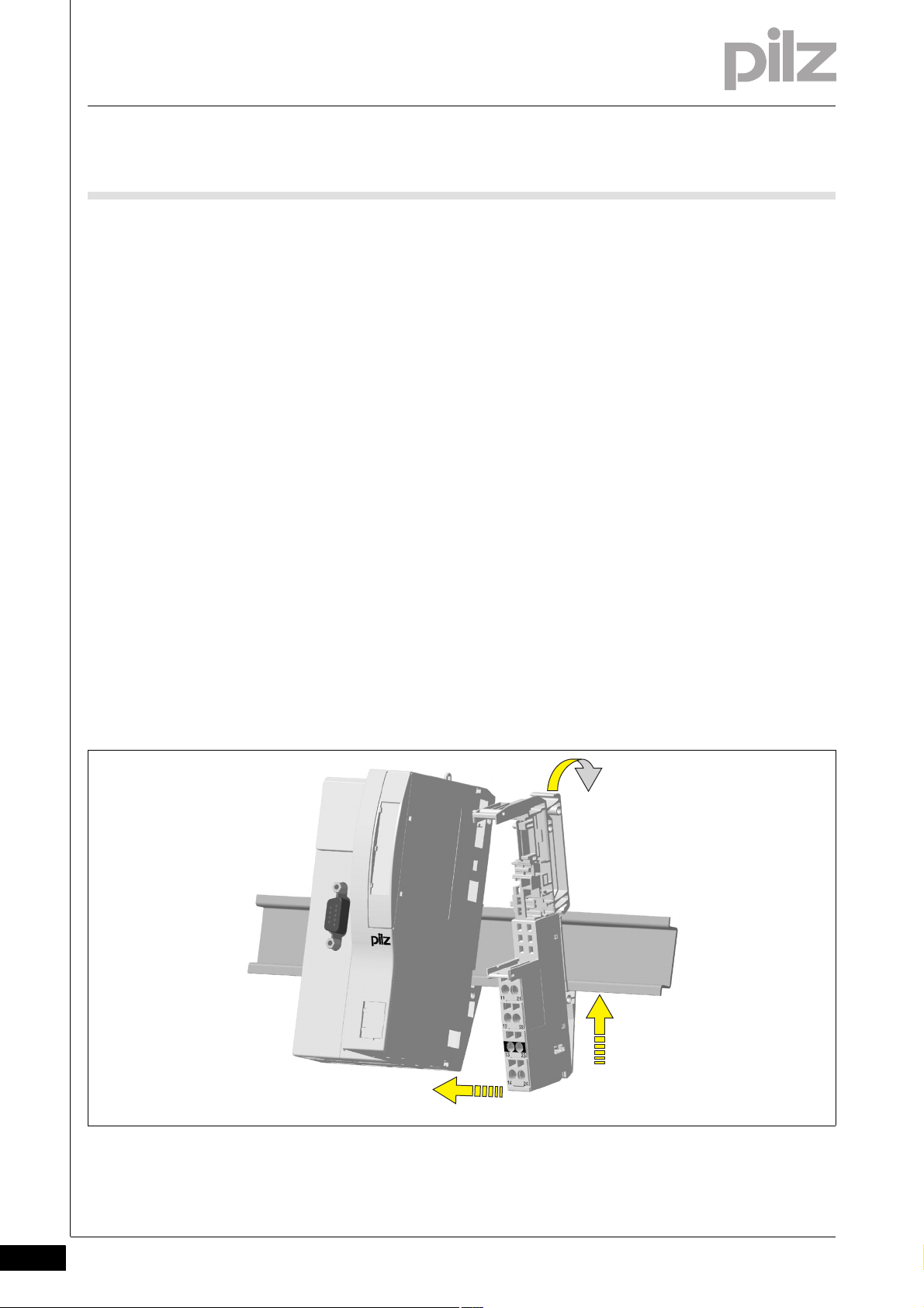
5.3.2 Removing an electronic module
Removing an electronic module5-][Elektronikmodul ziehen
Procedure:
Press the locking mechanisms [1] together simultaneously.
Pull out the electronic module [2].
Schematic representation:
5-4
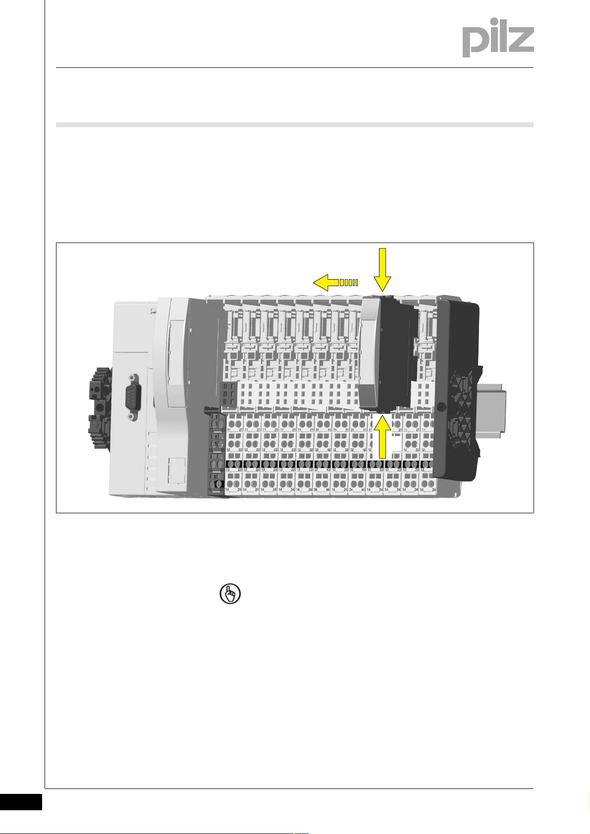
5.3.3 Changing an electronic module during operation
Changing an electronic module during operation5-][Montage BA Hot Swapping PS
NOTICE
Supply voltage modules may only be inserted and removed
when the supply voltage is switched off.
Pilz GmbH & Co. KG, Felix-Wankel-Straße 2, 73760 Ostfildern, Germany
Telephone: +49 711 3409-0, Telefax: +49 711 3409-133, E-Mail: pilz.gmbh@pilz.de
Page 27

6 Wiring
DIN 5264-A
6.1 General wiring guidelines
66000WiringWiring6-6.1General wiring g uidelines6100Gene ral wiring guideline s6-][Verdrahtung BA Einleitung
][Verdrahtung Kopf Versorgung
Please note:
The requirements of the supply voltages can be found in the chapter
entitled "Technical Details".
Safe electrical isolation must be ensured for the external power sup-
plies that generate the supply voltages. Failure to do so could result
in electric shock.
The external power supplies must comply with the current applicable
standard EN 60950-1, EN 61140, EN 50178 or EN 61558-1.
The maximum current load for the periphery supply on the module
bus is 10 A. Please refer to the derating diagram in the chapter entitled "Function Description".
The maximum current load for the C-rail is 10 A. Please refer to the
derating diagram in the chapter entitled "Function Description".
Permitted infeed at the C-rail:
–PE
–0 V
–Shield
– - 30 VDC ... +30 VDC
– - 48 VAC ... + 48 VAC
Earth the 0 V supply on the periphery supply or monitor each supply
group for earth faults.
The connection of the 0 V supply to the central earth bar or earth fault
monitor must be in accordance with the relevant national regulations
(e.g. EN 60204-1, NFPA 79:17-7, NEC: Article 250).
Details of the minimum range for cable cross sections on connection
terminals can be found in the section entitled "Technical Details".
Use copper wiring.
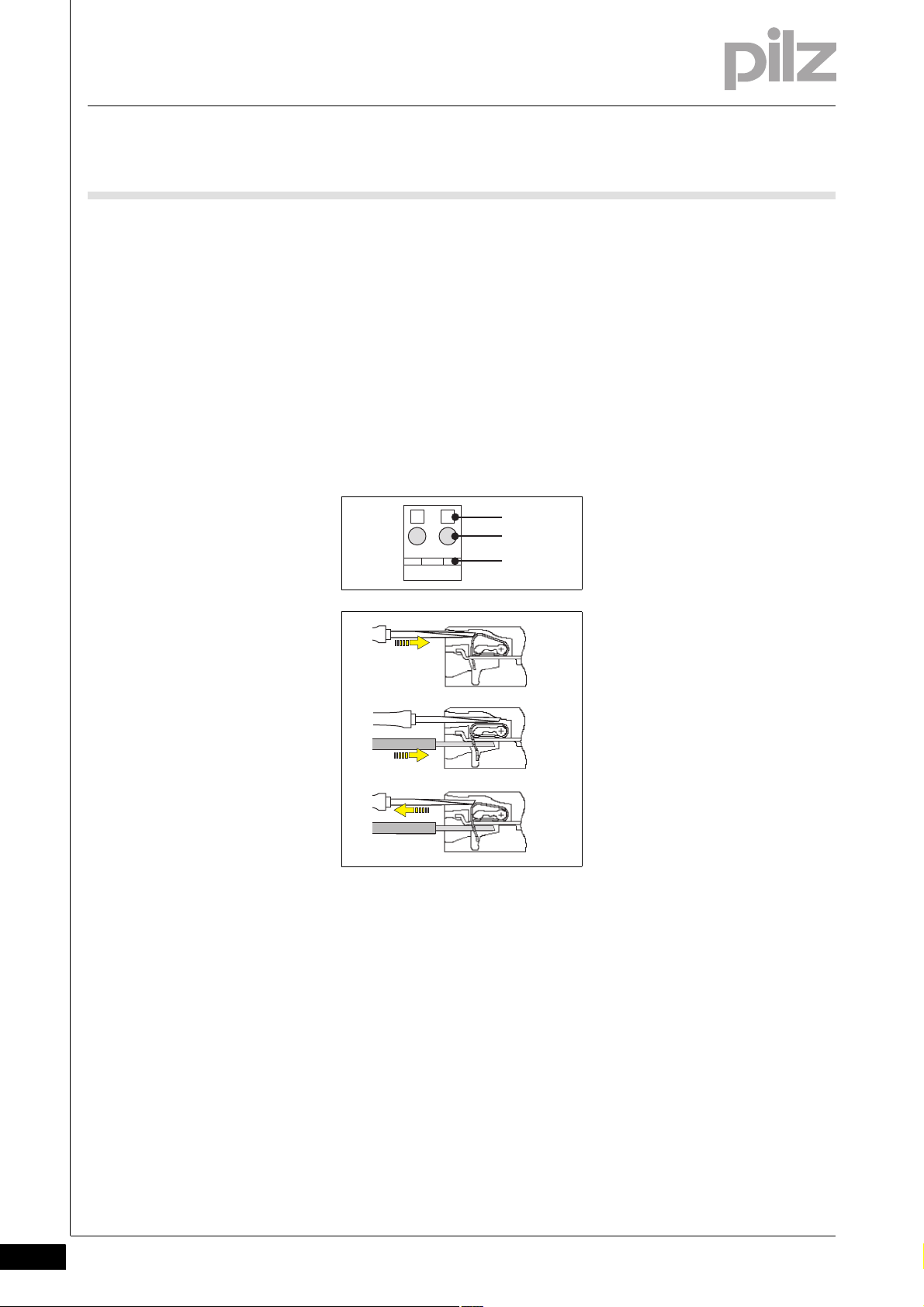
6.1.1 Mechanical connection of the base modules
Mechanical connection of the base modules6-][Modulverdrahtung mech
Procedure:
Use a flat blade screwdriver (DIN 5264-A)!
Strip the wire back 8 mm.
If necessary, label the connection level with a colour marker [3].
Pilz GmbH & Co. KG, Felix-Wankel-Straße 2, 73760 Ostfildern, Germany
Telephone: +49 711 3409-0, Telefax: +49 711 3409-133, E-Mail: pilz.gmbh@pilz.de
6-1
Page 28
6 Wiring
2111
[1]
[3]
[2]
[4]
[5]
[6]
6.1 General wiring guidelines
Base module with screw terminals:
– Use a screwdriver to loosen the screw on the screw terminal [1]
– Insert the stripped cable into the round fixing hole [2], as far as it
will go.
– Tighten up the screw on the screw terminal.
– Check that the cable is firmly seated.
Base module with cage clamp terminals:
– Insert the screwdriver [4] into the square hole [1].
– Insert the stripped cable into the round fixing hole [2], as far as it
will go [5].
– Pull out the screwdriver [6].
– Check that the cable is firmly seated.
6-2
][Modulverdrahtung el Sys A + B
Please note:
The minimum cable cross section for field connection terminals on the
base modules is 0.14 mm
The maximum cable cross section for field connection terminals is:
– Digital inputs: 1.5 mm
2
– Digital outputs: 2.0 mm
– Inputs/outputs on the counter modules: 1.5 mm
– Analogue inputs/outputs: 1.5 mm
– Communication cables: 1.5 mm
– Test pulse outputs: 1.5 mm
– Power supply: 2.5 mm
Pilz GmbH & Co. KG, Felix-Wankel-Straße 2, 73760 Ostfildern, Germany
Telephone: +49 711 3409-0, Telefax: +49 711 3409-133, E-Mail: pilz.gmbh@pilz.de
– Functional earth: 2.5 mm
2
2
(AWG26)
(AWG16)
2
(AWG14)
2
(AWG16)
(AWG12)
2
(AWG12)
2
(AWG16)
2
(AWG16)
2
(AWG16)
Page 29

6 Wiring
6.1 General wiring guidelines
On base modules with screw terminals:
– If you use a multi-strand cable to connect the I/Os, it is recom-
mended that you use ferrules conforming to Parts 1 and 2 of DIN
46228, 0.14 ... 1.5 mm
To crimp the ferrules you can use crimp pliers (crimp form A or C)
conforming to EN 60947-1, such as the PZ 1.5 or PZ 6.5 from
Weidmüller, for example.
– Maximum torque setting: 0.8 Nm
Use copper wiring.
2
, Form A or C, although this is not essential.
Pilz GmbH & Co. KG, Felix-Wankel-Straße 2, 73760 Ostfildern, Germany
Telephone: +49 711 3409-0, Telefax: +49 711 3409-133, E-Mail: pilz.gmbh@pilz.de
6-3
Page 30
6 Wiring
2111
2212
2313
2414
Head Module
I/O Module
I/O Module
I/O Module
I/O Module
Periphery Supply
(24 V DC)
C-rail Supply
Infeed for
Module Supply
(24 V DC)
Module bus
[ . . . ]
PSSu E F PS(-T)
[ . . . ]
I/O Module
5 V DC
24 V DC
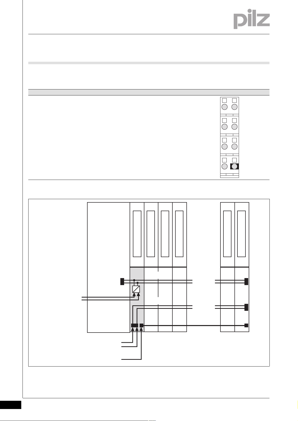
6.2 Terminal configuration
6.2Terminal configuration6200Terminal configuration6-][Klemmenbelegung PS
For use as a general supply module, supplying a head module and
subsequent modules
Base module Terminal configuration
Screw terminals:
PSSu BS 1/8S
PSSu BS 1/8S-T
Cage clamp terminals:
PSSu BS 1/8C
PSSu BS 1/8C-T
11: +24 V infeed for module supply
21: 0 V infeed for module supply
12-22: 0 V periphery supply,
interrupted to the left
(12-22 linked within the base module)
13-23: +24 V periphery supply,
interrupted to the left
(13-23 linked within the base module)
14-24 C-rail supply,
interrupted to the left
(14-24 linked within the base module)
6-4
Pilz GmbH & Co. KG, Felix-Wankel-Straße 2, 73760 Ostfildern, Germany
Telephone: +49 711 3409-0, Telefax: +49 711 3409-133, E-Mail: pilz.gmbh@pilz.de
Page 31

6 Wiring
2111
2212
2313
2414
6.2 Terminal configuration
For use as a supply module to refresh the module supply and periph-
ery supply
For use as a supply module to form supply groups
– To interrupt the incoming periphery supply and C-rail
– To provide subsequent modules with the module supply, periphery
supply and C-rail supply
With these base modules the supply module cannot be used as the
first module after the head module.
Base module Terminal configuration
Screw terminals:
PSSu BS-R 1/8S
PSSu BS-R 1/8S-T
Cage clamp terminals:
PSSu BS-R 1/8C
PSSu BS-R 1/8C-T
11: +24 V infeed for module supply,
interrupted to the left
21: 0 V infeed for module supply
12-22: 0 V periphery supply,
interrupted to the left
(12-22 linked within the base module)
13-23: +24 V periphery supply,
interrupted to the left
(13-23 linked within the base module)
14-24 C-rail supply,
interrupted to the left
(14-24 linked within the base module)
Pilz GmbH & Co. KG, Felix-Wankel-Straße 2, 73760 Ostfildern, Germany
Telephone: +49 711 3409-0, Telefax: +49 711 3409-133, E-Mail: pilz.gmbh@pilz.de
6-5
Page 32

6 Wiring
PSSu E F PS(-T)
I/O Module
Periphery Supply
(24 V DC)
Infeed for
Module Supply
(24 V DC)
I/O Module
Power Supply
[ . . . ]
Refreshing of
Periphery Supply
(24 V DC)
C-rail Supply
Refreshing of
Module Supply
(24 V DC)
I/O Module
Head Module
Module bus
[ . . . ]
I/O Module
5 V DC
24 V DC
0 V
5 V DC
0 V
24 V DC
6.2 Terminal configuration
6-6
Pilz GmbH & Co. KG, Felix-Wankel-Straße 2, 73760 Ostfildern, Germany
Telephone: +49 711 3409-0, Telefax: +49 711 3409-133, E-Mail: pilz.gmbh@pilz.de
Page 33

6 Wiring
2111
2212
2313
2414
+24 V DC
0 V DC
Module Supply
Periphery Supply
0 V DC
+24 V DC
Connect to the C-rail Supply
=
~
NL1
=
~
NL1
Connect to the 0 V supply and
earth at a single point
PSSu E F PS/
PSSu E F PS-T with
- PSSu BS 1/8S(-T)
- PSSu BS 1/8C(-T)
or
- PSSu BS-R 1/8S(-T)
- PSSu BS-R 1/8C(-T)
2111
2212
2313
2414
+24 V DC
0 V DC
Module Supply
Periphery Supply
Connect to the C-rail Supply
=
~
NL1
Connect to the 0 V supply and
earth at a single point
PSSu E F PS/
PSSu E F PS-T mit
- PSSu BS 1/8S(-T)
- PSSu BS 1/8C(-T)
oder
- PSSu BS-R 1/8S(-T)
- PSSu BS-R 1/8C(-T)
6.3 Connecting the module
6.3Connecting the module6300Connecting the module6-][Anschluss PS
Separate power supplies for module supply and periphery supply
Common power supply for module supply and periphery supply
Pilz GmbH & Co. KG, Felix-Wankel-Straße 2, 73760 Ostfildern, Germany
Telephone: +49 711 3409-0, Telefax: +49 711 3409-133, E-Mail: pilz.gmbh@pilz.de
6-7
Page 34

6 Wiring
6-8
Pilz GmbH & Co. KG, Felix-Wankel-Straße 2, 73760 Ostfildern, Germany
Telephone: +49 711 3409-0, Telefax: +49 711 3409-133, E-Mail: pilz.gmbh@pilz.de
Page 35

7 Operation
7.1 Messages
77000OperationOperation7-7.1Messages71 00Messages7-][BA_Betrie b Störung LED "Err" PS
A module error is displayed via the “Err” LED (see section entitled “Display elements”), signalled to the head module and then entered in the
][BA_Betrieb Fehler FS PS
Module error Explanation Remedy
Start-up error Error as the PSSu system starts up Change faulty module.
Configuration error Incorrect module type configured. The configured hardware registry does
FS communication error Error during FS communication Change faulty module.
Temperature error: too warm Ambient temperature too high:
Overvoltage error A system voltage or infeed is too high. Stabilise the supply or change the
Undervoltage error A system voltage or infeed is too low. Stabilise the supply or change the
Error in the overvoltage protection diodes
head module's error stack or diagnostic log.
The module can detect the following errors:
not match the actual hardware registry.
Ensure there is sufficient ventilation in
Entry in the error stack or diagnostic
log
Overvoltage protection diodes are defective.
the control cabinet or prevent over-
load.
faulty supply voltage module.
faulty supply voltage module.
Change faulty supply voltage module.
Further information on PSSu error messages is available in the online
help for PSS WIN-PRO or PAS4000.
Pilz GmbH & Co. KG, Felix-Wankel-Straße 2, 73760 Ostfildern, Germany
Telephone: +49 711 3409-0, Telefax: +49 711 3409-133, E-Mail: pilz.gmbh@pilz.de
7-1
Page 36
7 Operation
Err
11I021
I1
Err
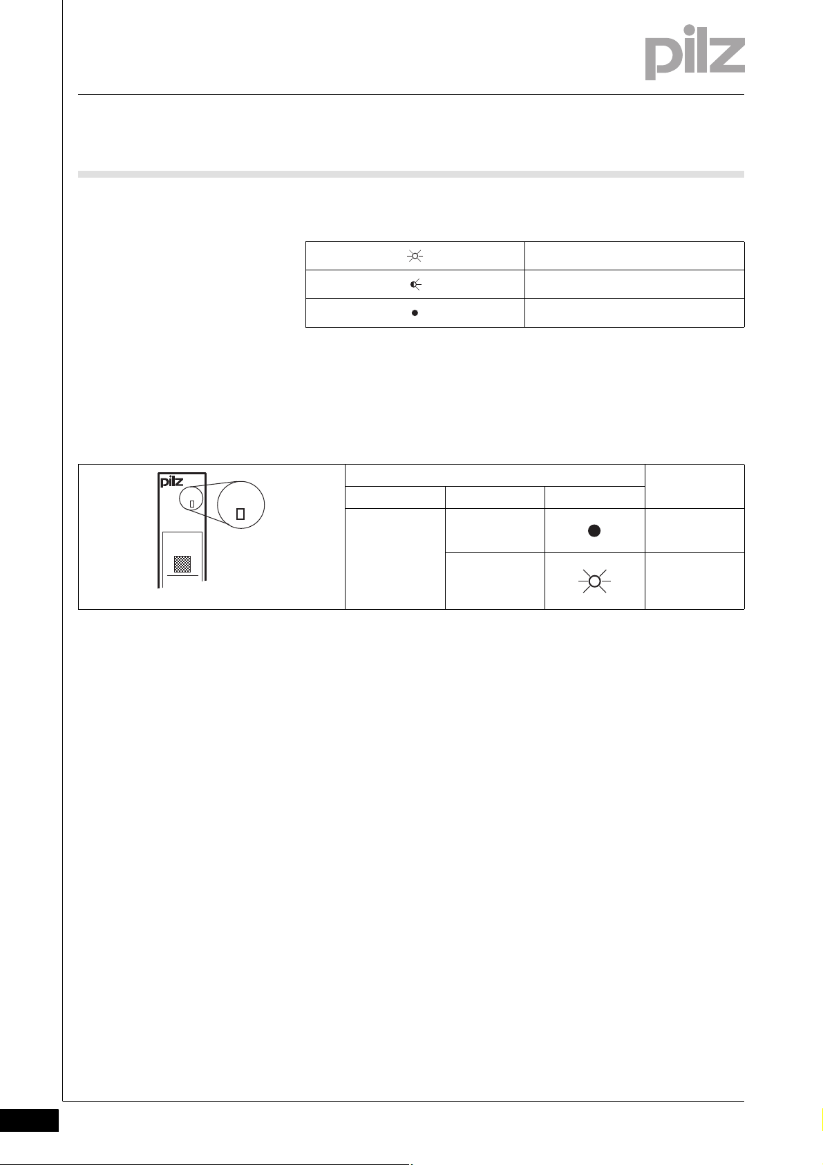
7.2 Display elements
7.2Display elements7200Display elements7-Anzeige Legende 3x
Legend:
7.2.1 Anzeigeelemente zur Moduldiagnose
Anzeigeelemente zur Moduldiagnose7-][BA_A nzeige LED Err
The module has an LED for displaying module errors (“Err” LED).
LED on
LED flashes
LED off
LED Key
Name Colour Status
Err - - - No error
red Module error
7-2
Pilz GmbH & Co. KG, Felix-Wankel-Straße 2, 73760 Ostfildern, Germany
Telephone: +49 711 3409-0, Telefax: +49 711 3409-133, E-Mail: pilz.gmbh@pilz.de
Page 37

7 Operation
Err
11 21
5 V 24 V
0V24V
5V 24V
7.2 Display elements
7.2.2 Display elements for the status of the module supply and periphery supply
Display elements for the status of the module supply and periphery supply7-][BA_Anzeige LED PS
A status LED is assigned to both the module supply and periphery supply ("5 V" and "24 V" LEDs).
LED Key
Description Colour State
5 V - - - No supply volt-
age or error in
the supply voltage for module
supply
Green Error-free sup-
ply voltage for
module supply
24 V - - - Error in the sup-
ply voltage for
periphery supply
Green No supply volt-
age for periphery supply
Red Supply voltage
for periphery
supply is errorfree
Pilz GmbH & Co. KG, Felix-Wankel-Straße 2, 73760 Ostfildern, Germany
Telephone: +49 711 3409-0, Telefax: +49 711 3409-133, E-Mail: pilz.gmbh@pilz.de
7-3
Page 38

7 Operation
7.3 Status byte
7.3Status byte7300Status byte7-][BA_Betrieb FS Versorgung Statusbyte
The first supply module after the head module can communicate a variety of status information to the ST-PII (see table below). The information
is transmitted using the module's status byte. Read access (R) is configured for that purpose.
Structure and contents of the status byte
Bit number Signal Key
0 0 SafetyBUS p in a STOP condition
1 SafetyBUS p in a RUN condition
1 0 The PSSu section configured for the FS inputs (section A or B) is in a STOP condition.
1 The PSSu section configured for the FS inputs (section A or B) is in a RUN condition.
2 0 The PSSu section configured for the FS outputs (section A) is in a STOP condition.
1 The PSSu section configured for the FS outputs (section A) is in a RUN condition.
3 0 No general error in the PSSu FS section
1 General error in the PSSu FS section
4 0 No general error in the PSSu ST section
1 General error in the PSSu ST section
5 0 No error on the FS modules
1 At least one FS module is registering an error
6 0 No error on the ST modules
1 At least one ST module is registering an error
70 Reserved
1
7-4
Pilz GmbH & Co. KG, Felix-Wankel-Straße 2, 73760 Ostfildern, Germany
Telephone: +49 711 3409-0, Telefax: +49 711 3409-133, E-Mail: pilz.gmbh@pilz.de
Page 39

8 Technical details
8.1 Technical details
88000Technical detailsTechnical details8-8.1Technical details8100Technical details8-][Technische Daten PSSu Versorgung Periphery/Module_neu
Technical details
Application range Standard/Failsafe
Module's device code 0801h
Support in system environment A
from FS firmware version for other head modules 4
from ST firmware version for other head modules 5
from FS firmware version PSSu H F PN 1
from ST firmware version PSSu H S PN 1
from ST firmware version PSSu WR S IDN 6
Support in system environment B
from head module FS firmware version 1 0.0
from head module ST firmware version 1.0.0
Electrical data
Infeed for Module Supply
Voltage 24 V DC
Voltage tolerance -30 %/+25 %
Output of external power supply (DC) 9.0 W
Max. continuous current that the external power supply
must provide
Inrush current that the external power supply must provide 4.0 A
Module's current consumption 23 mA
Module's power consumption 0.12 W
Infeed for Periphery Supply
Voltage 24 V DC
Voltage tolerance -30 %/+25 %
Max. continuous current that the external power supply
must provide
Voltage output Module Supply
Voltage 5 V DC
Voltage tolerance -2 %/+3 %
Current load capacity 1.5 A
Short circuit-proof yes
Potential isolation between Module Supply and
Periphery Supply
Max. power dissipation of the module 1.50 W
Environmental data
Climatic suitability EN 60068-2-14, EN 60068-2-1, EN 60068-2-2,
Ambient temperature 0 - 60 °C
Max. ambient temperature in accordance with UL 508 60 °C
Storage temperature -25 - 70 °C
Climatic suitability in accordance with EN 60068-2-30,
EN 60068-2-78
Condensation no
Max. operating height above sea level 5000 m coated version (-T)
EMC EN 61000-4-2, EN 61000-4-3, EN 61000-4-4,
0.6 A
10.0 A
3050 V
EN 60068-2-30, EN 60068-2-78
-40 - 70 °C coated version (-T)
-40 - 70 °C coated version (-T)
93 % r. h. at 40 °C
yes coated version (-T)
EN 61000-4-5, EN 61000-4-6, EN 61000-6-2,
EN 61000-6-4
Pilz GmbH & Co. KG, Felix-Wankel-Straße 2, 73760 Ostfildern, Germany
Telephone: +49 711 3409-0, Telefax: +49 711 3409-133, E-Mail: pilz.gmbh@pilz.de
8-1
Page 40
8 Technical details
8.1 Technical details
Environmental data
Vibration to EN 60068-2-6
Frequency 10 - 150 Hz
10 - 1,000 Hz coated version (-T)
Max. acceleration 1g
5g coated version (-T)
Shock stress
EN 60068-2-27 15g
11 ms
EN 60068-2-29 10g
25g coated version (-T)
16 ms
6 ms coated version (-T)
Protection type in accordance with EN 60529
Mounting (e.g. cabinet) IP54
Housing IP20
Terminals IP20
Airgap creepage in accordance with EN 60664-1
Overvoltage category II
Pollution degree 2
Mechanical data
Housing material
Front PC
Bottom PC
Coding PA
Dimensions
Height 76.0 mm
Width 12.6 mm
Depth 60.2 mm
Weight 38 g
40 g coated version (-T)
Mechanical coding
Type B
Colour yellow
8-2
Technische Daten_Satz No rmen
Pilz GmbH & Co. KG, Felix-Wankel-Straße 2, 73760 Ostfildern, Germany
Telephone: +49 711 3409-0, Telefax: +49 711 3409-133, E-Mail: pilz.gmbh@pilz.de
Page 41

8 Technical details
8.2 Order reference
8.2Order reference8200Order reference8-Bestelldaten
Order reference
Description Order no.
PSSu E F PS
(Electronic module)
PSSu E F PS-T
(Electronic module, coated version)
][Bestelldaten Basismodule BS mit R 1/8 mit -T
Base modules Order no.
PSSu BS 1/8S
(Base module with screw terminals, for use only as the first
module after the head module)
PSSu BS 1/8S-T
(Base module with screw terminals, for use only as the first
module after the head module, coated version)
PSSu BS 1/8C
(Base module with cage clamp terminals, for use only as
the first module after the head module)
PSSu BS 1/8C-T
(Base module with cage clamp terminals, for use only as
the first module after the head module, coated version)
PSSu BS-R 1/8S
(Base module with screw terminals, for use only to refresh
the voltage and form supply groups)
PSSu BS-R 1/8S-T
(Base module with screw terminals, for use only to refresh
the voltage and form supply groups, coated version)
PSSu BS-R 1/8C
(Base module with cage clamp terminals, for use only to refresh the voltage and form supply groups)
PSSu BS-R 1/8C-T
(Base module with cage clamp terminals, for use only to refresh the voltage and form supply groups, coated version)
312 190
314 190
312 650
314 650
312 651
314 651
312 652
314 652
312 653
314 653
Pilz GmbH & Co. KG, Felix-Wankel-Straße 2, 73760 Ostfildern, Germany
Telephone: +49 711 3409-0, Telefax: +49 711 3409-133, E-Mail: pilz.gmbh@pilz.de
8-3
Page 42

8 Technical details
8-4
Pilz GmbH & Co. KG, Felix-Wankel-Straße 2, 73760 Ostfildern, Germany
Telephone: +49 711 3409-0, Telefax: +49 711 3409-133, E-Mail: pilz.gmbh@pilz.de
Page 43

...
21292-EN-04, 2011-04 Printed in Germany
© Pilz GmbH & Co. KG, 2011
+49 711 3409-444
support@pilz.com
Pilz GmbH & Co. KG
Felix-Wankel-Straße 2
73760 Ostfildern, Germany
Telephone: +49 711 3409-0
Telefax: +49 711 3409-133
E-Mail: pilz.gmbh@pilz.de
Internet: www.pilz.com
Technical support
In many countries we are
represented by our subsidiaries
and sales partners.
Please refer to our homepage
for further details or contact our
headquarters.
InduraNET p
®
, Pilz
®
, PIT
®
, PMCprotego
®
, PMI
®
, PNOZ
®
, Primo
®
, PSEN
®
, PSS
®
, PVIS
®
, SafetyBUS p
®
, SafetyEYE
®
, SafetyNET p
®
, the spirit of safety
®
are registered and protected trademarks
of Pilz GmbH & Co. KG in some countries. We would point out that product features may vary from the details stated in this document, depending on the status at the time of publication and the scope
of the equipment. We accept no responsibility for the validity, accuracy and entirety of the text and graphics presented in this information. Please contact our Technical Support if you have any questions.
Contact address
 Loading...