

Electronic Monitoring Relays
Evaluating analogue signals
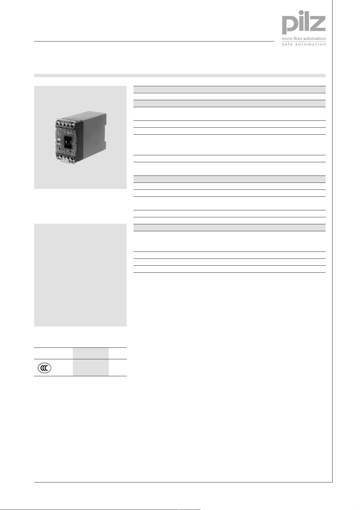
P1K
Technical Details P1K
Electrical data
Supply voltage AC: 24, 42, 48, 100, 110, 115, 120, 127,
Tolerance 85 ... 110 %
Power consumption Approx. 3.5 VA
Switching capability in accordance
with EN 60947-4-1, 10/91 AC1: 240 V/5 A/1200 VA
Output contacts 2 auxiliary contacts (1 N/O + 1 N/C)
Contact fuse protection in accordance 6 A quick or 4 A slow
with EN 60947-5-1, 10/91
Measuring circuit
Response value 0 ... 9.9 VDC
Release value Uon -1 ... 30 %
The P1K comparator is used to
compare voltage signals with a
reference value.
Features
● Response triggered when
voltage exceeds the switching
threshold
● Suitable for use with true
power monitors
● Analogue input 0 ... 9.9 V
● Offset setting
● Digital setting
● Output signal can be either
latching or non-latching
● Operates to normally energised
or normally de-energised mode.
Approvals
P1K
●
Max. overload +14.8 V (current flow 3 mA)
Response delay 0.1 ... 3 s adjustable
Memory time offset Min. 200 ms
Mechanical data
Max. cable cross section 2 x 2.5 mm
of external conductor Single-core or multi-core with crimp
Torque setting for connection terminals 1.2 Nm (screws)
Dimensions (H x W x D) 75 x 45 x 110 mm
Weight 300 g
Description
The P1K is enclosed in a P-75
housing. There are 10 versions
available for AC operation.
Features:
● Relay outputs: 2 auxiliary contacts
(1 N/O and 1 N/C)
● Digitally adjustable response value
from 0 ... 99 % of the nominal
value
● Adjustable response delay
● Adjustable start-up suppression
time
● Automatic or manual reset
● LED for status display
● Versions available for digital or
analogue remote control operation
230, 240 V
DC1: 24 V/5 A/250 W
- 12 V DC (current flow 3 mA)
2
connector
The P1K is used to compare true
and set values. The output relay
switches if the measuring voltage
exceeds the response value. The
release value is adjustable from 1 to
30 %. If the measuring voltage falls
below the release value, the output
relay returns to its original position.
The offset function causes the unit to
operate using differential evaluation.
This offsets the response value.
If the permitted voltage range is
reached once more the device will
start automatically if set to automatic
reset. If manual reset is used, the
supply voltage must be interrupted
using an external reset button.
4
Pilz GmbH & Co. KG, Sichere Automation, Felix-Wankel-Straße 2, 73760 Ostfildern, Germany
Telephone: +49 711 3409-0, Telefax: +49 711 3409-133, E-Mail: pilz.gmbh@pilz.de
NSG-D-2-239-2005-04
Electronic Monitoring Relays
Evaluating analogue signals
P1K
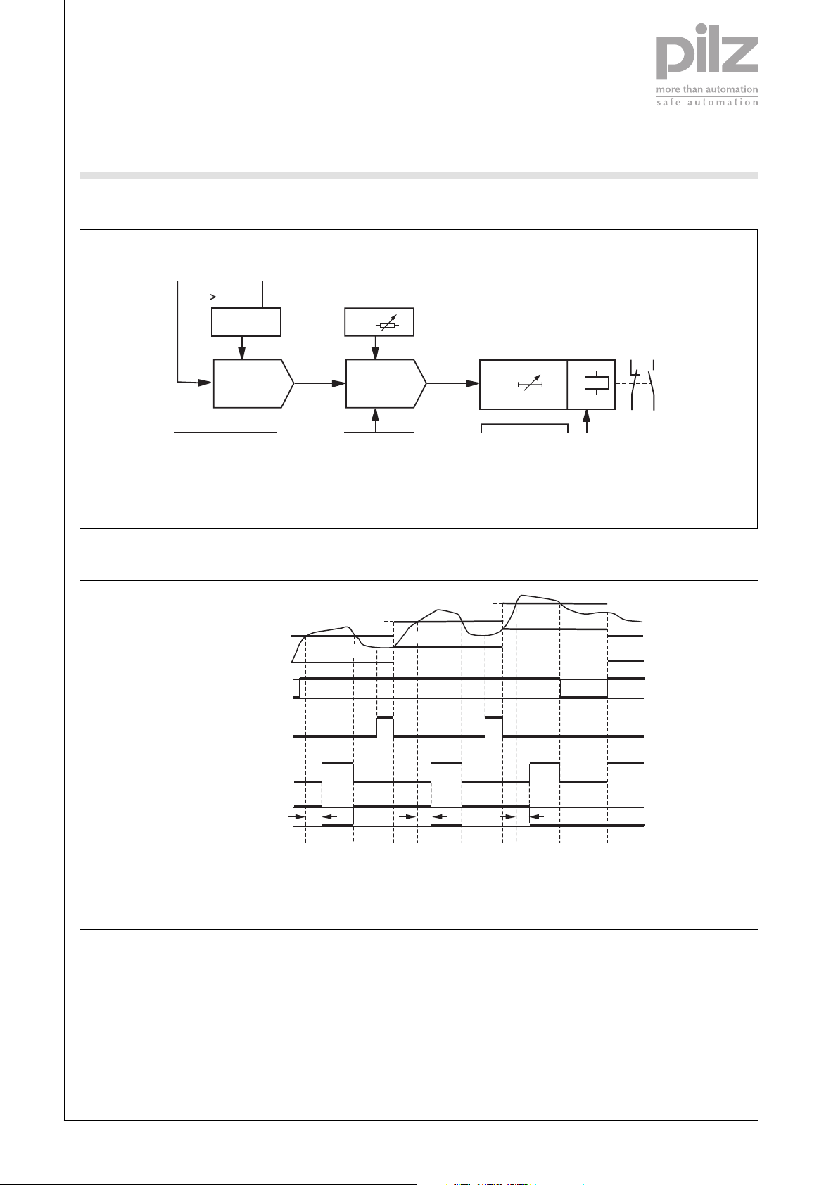
Block diagram
4
U
Response value
on
U
Release value
off
U
Measuring voltage
M
Timing diagram
U(+)
Measuring circuit
Supply voltage U
Offset (Y1-N)
Output (K1, AB)
Output (K1, RB)
N
U
M
U
Off
UM-U
B
Y1
Off
U
on
23
11
U
int
U
U
t
U
M
U
on
0V
1
0
1
0
1
0
1
t
r
0
UM>U
U
int>Uon
Offset voltage
Off
Internal measuring voltage
int
Response delay
r
Uon+U
Off
=0V
U
Off
(1)
on
t
r
Uon+U
Off
U
Off
U
=2V
Off
(1)
t
r
UM>U
on
t
r
UM>U
=5V
K1
12
24
U
=0V
Off
(2)
on
RB Normally energised mode
AB Normally de-energised mode
(1) Set offset
(2) Set offset to 0 V
Pilz GmbH & Co. KG, Sichere Automation, Felix-Wankel-Straße 2, 73760 Ostfildern, Germany
Telephone: +49 711 3409-0, Telefax: +49 711 3409-133, E-Mail: pilz.gmbh@pilz.de
NSG-D-2-239-2005-04

Electronic Monitoring Relays
Evaluating analogue signals
P1K
Connection example
L1
L2
L3
U
B
1L1
1L2
L1 L2 Y1N
P1WP
K1
M 3~
0V
k U/I N ±U
L3
±I
V
U
W
A1 11 23
P1K/FFB
12 24
K1
Z2Z1 Z3
U(+)
NA2
A1 11 23
P1KU/FFB
12 24
Y1N
Z2Z1 Z3
U(+)
NA2
FBFB
A1 15 25
PW-1PK
16 18 26 A2
28
4
Pilz GmbH & Co. KG, Sichere Automation, Felix-Wankel-Straße 2, 73760 Ostfildern, Germany
Telephone: +49 711 3409-0, Telefax: +49 711 3409-133, E-Mail: pilz.gmbh@pilz.de
NSG-D-2-239-2005-04

Electronic Monitoring Relays
Evaluating analogue signals
P1K
General Data
Unless stated otherwise in the technical details for the specific unit.
Electrical data
AC frequency range 50 ... 60 Hz
DC residual ripple 160 %
Contact material AgCdO
Continuous duty 100 %
Environmental data
EMC EN 50 081-1, 01/92; EN 50.082-2, 03/95
Vibration in accordance Frequency: 10 ... 55 Hz,
with EN 60068-2-6, 04/95 Amplitude: 0.35 mm
Climatic suitability IEC 60068-2-3, 1969
Airgap creepage DIN VDE 0110-1, 04/97
Ambient temperature -10 ... +55 °C
Storage temperature -40 ... +85 °C
Mechanical data
Torque setting for connection terminals 0.6 Nm (screws)
Mounting position Any
Housing material Thermoplastic Noryl SE 100
Protection types Mounting: IP 54
Housing: IP 40
Terminals: IP 20
4
Order references key
U
B
R
i
Remote c. Remote control
Supply voltage
Internal resistance
Order references
Type U
P1K 110 VAC 6.3 kΩ 490 230
P1K 120 VAC 6.3 kΩ 490 240
P1K 230 VAC 250 kΩ 490 251
P1K 230 VAC 6.3 kΩ 490 250
P1K 240 VAC 6.3 kΩ 490 255
P1K 24 VAC 6.3 kΩ 490 200
P1K 42 VAC 6.3 kΩ 490 210
Type U
P1K-FFB 24 VAC 6.3 kΩ digital 490 300
P1K-FFB 115 VAC 6.3 kΩ digital 490 335
P1K-FFB 230 VAC 6.3 kΩ digital 490 350
FB decoding switch 2 dec P1U (Remote control for P1K digital) 209 470
P1K-FFB 110 V AC 10 kΩ analogue 490 338
P1K-FFB 230 VAC 10 kΩ analogue 490 339
FB F11 (remote control for P1K analogue) 10 kΩ neutral scale 326 903
B
B
R
i
R
i
Remote control
Order no.
Order no.
Pilz GmbH & Co. KG, Sichere Automation, Felix-Wankel-Straße 2, 73760 Ostfildern, Germany
Telephone: +49 711 3409-0, Telefax: +49 711 3409-133, E-Mail: pilz.gmbh@pilz.de
NSG-D-2-239-2005-04
 Loading...