

Page 1
Two-hand Relays
EN 574, Type IIIA
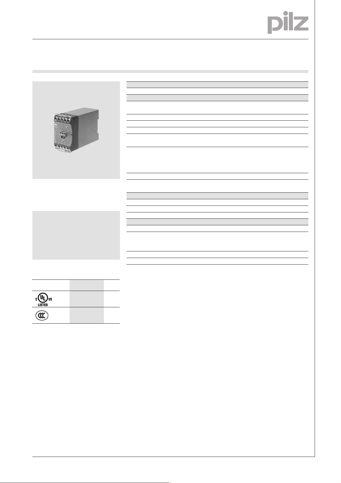
P1HZ 2V
Two-hand relay in accordance with
VDE 0113-1, 11/98, EN 60204-1,
12/97 and IEC 204-1, 11-98
Features
● Conforms to EN 574, Type IIIA
with partial fail to safety and in
accordance with EN 954,
Category 1
Approvals
Technical Details P1HZ 2V
Electrical Data
Supply Voltage AC: 24, 42, 110, 120, 230 V
DC: 24 V
Tolerance 85 ... 110 %
Residual Ripple DC Max. 20 %
Power Consumption Approx. 4 VA/2 W
Voltage and Current at the 24 VDC, 40 mA
Input Circuits 1/2
Switching Capability in accordance with
EN 60947-4-1, 01/00 AC1: 240 V/6 A/1500 VA
DC1: 24 V/1,5 A/40 W
EN 60947-5-1, 08/00 (DC13: 6 cycles/min.) AC15: 230 V/2.5 A; DC13: 24 V/1.5 A
Output Contacts 2 safety contacts (N/O)
Contact Fuse Protection 6 A quick or 4 A slow
(EN 60947-5-1, 08/00)
Times
Delay-on Energisation (EN 574) 10 ms
Delay-on De-energisation Approx. 30 ms
Simultaneity channel 1/2 Max. 500 ms
Mechanical Data
Torque Setting on Connection Terminals 1.2 Nm (screws)
Maximum Cross Section of 2 x 2.5 mm
External Conductors Single-core or multi-core with
crimp connectors
Dimensions (H x W x D) 75 x 45 x 115 mm
Weight AC: 380 g, DC: 280 g
Description
2
3
P1HZ 2V
●
●
● 45 mm, P-75-housing, DIN-Rail
mounting
● Positive-guided relay outputs:
2 safety contacts (N/O)
● Increase in the number of
safety contacts available by
connecting expander modules.
Function Description
The two-hand relay is not suitable for
use as the primary safety device on
mechanical and hydraulic presses or
in safety circuits for type IIIC
applications. For such applications
we recommend using the P2HZ 5 or
P2HZ X1.
A cycle can only be initiated by
pressing the two pushbuttons
simultaneously. A cycle is interrupted
by releasing one or both buttons to
stop the output.
The output signal can only be
reinitiated after both inputs have
been released and the pushbuttons
are operated again.
NSG-D-2-082-2008-10
Page 2
Two-hand Relays
EN 574, Type IIIA
P1HZ 2V
3
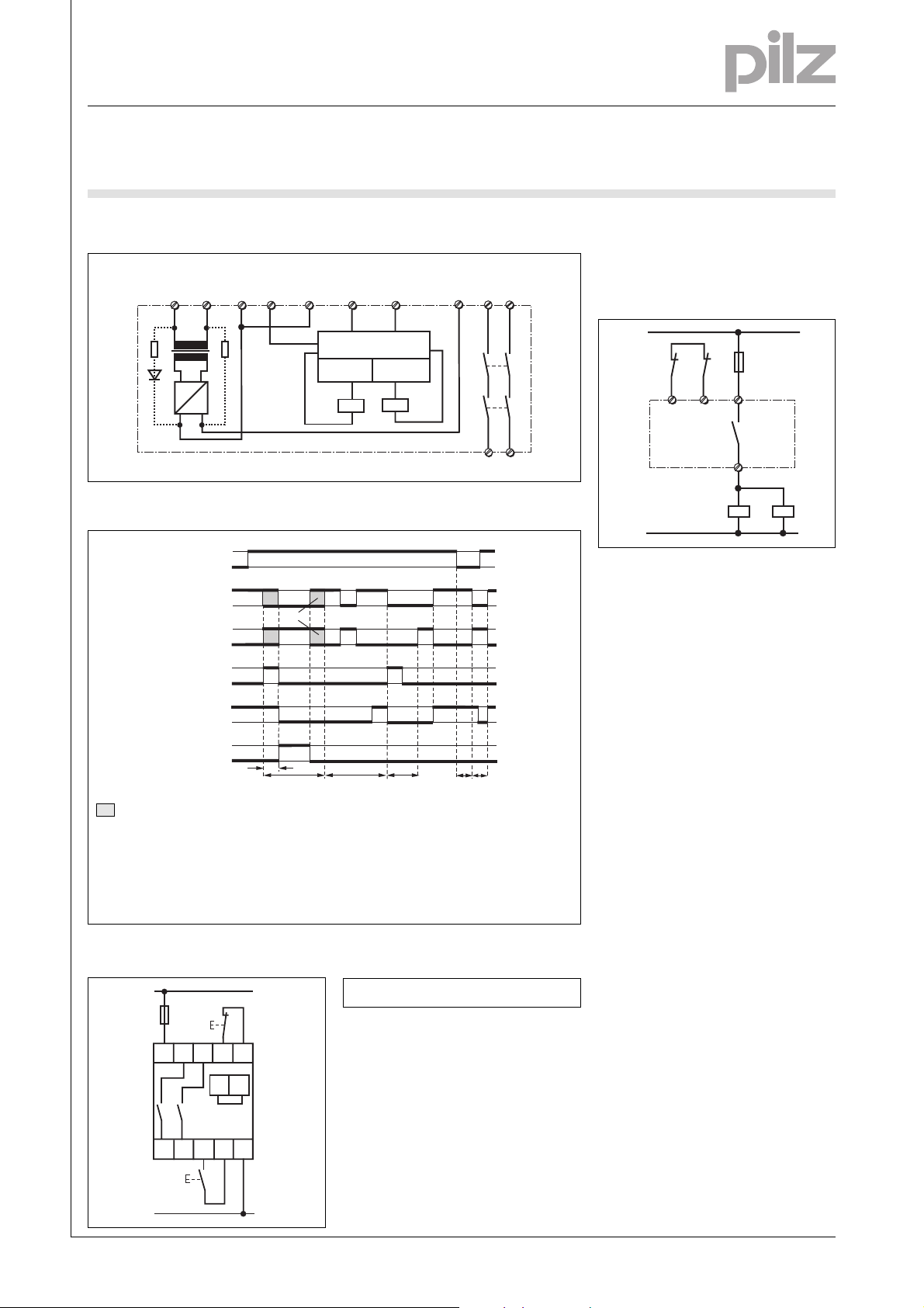
Internal Wiring Diagram
Feedback
U
B
control loop
A2
A1
(L-)
(L+)
T1
~
G1
=
+
Function Diagram
1
U
B
0
Output
1
0
1
0
1
0
1
0
1
0
Input circuit 1
Input cirucit 2
Simultaneity
Feedback
control loop
3231
tg
Input circuit 1
11
(6)
(1)
Switch-on delay/
Cycle test
Channel 1
K2K1
(2)
Input circuit 2
Channel 2
(3)
● Increase in safety contacts
The number of output contacts can
Safety
contacts
2412 21
33 43
K1
K2
34 44
tg
(5)
(4)
be increased by using expander
modules or relays/contactors with
positive-guided contacts.
1L1
(1L+)
F2
33
34
K3 K4
1L2
(1L-)
K3
31 32
K4
No significance
Feedback control loop open: 0
Feedback control loop closed: 1
(1): Normal working cycle
(2): Fault: feedback control loop not closed
at least 0.5 s before input circuit 1/2
1L1
(1L+)
F1
S1
1L2
(1L-)
A1
33
(+)
44
34
S2
12
11
43
31
32
A2
24
21
(-)
(3): Fault: difference in
input circuit 1/2 > t
(4): Fault:input circuit
1/2 closed before U
(5): Fault: feedback control loop not
open before cycle t
(6): Undefined time period
g
B
g
– KeyConnection Example
S1/S2: Two-hand pushbuttons
NSG-D-2-082-2008-10
Page 3

Two-hand Relays
EN 574, Type IIIA
P1HZ 2V
General Technical Data
Unless stated otherwise in the technical details for the specific unit
Electrical Data
Frequency Range AC 50 ... 60 Hz
Residual Ripple DC 160 %
Contact Material AgSnO
Continuous Duty 100 %
Environmental Data
EMC EN 50081-1, 01/92, EN 61000-6-2, 03/00
Vibration in accordance with Frequency: 10 ... 55 Hz,
EN 60068-2-6, 01/00 Amplitude: 0.35 mm
Climatic Suitability DIN IEC 60068-2-3, 12/86
Airgap Creepage DIN VDE 0110 part 1, 04/97
Ambient Temperature -10 ... +55 °C
Storage Temperature -40 ... +85 °C
Mechanical Data
Torque Setting on Connection Terminals 1.2 Nm (screws)
Mounting Position Any
Housing Material Thermoplast Noryl SE 100
Protection Mounting: IP 54
2
Housing: IP 40
Terminal Range: IP 20
3
The units were tested in accordance with the relevant standards current at
the time of development.
Order References
Type U
P1HZ 2V 24 V DC 474 505
P1HZ 2V 24 V AC 474 501
P1HZ 2V 42 V AC 474 511
P1HZ 2V 110 V AC 474 531
P1HZ 2V 120 V AC 474 535
P1HZ 2V 230 V AC 474 551
B
Order No.
NSG-D-2-082-2008-10
 Loading...