

Page 1

Electronic Monitoring Relays
Earth fault monitoring
P1E-2NK
Technical Details P1E 2NK
Electrical data
Supply voltage AC: 24/42, 110/230, 110/240, 400, 500 V
Tolerance 85 ... 110 %
Power consumption AC: approx. 6.5 VA
Switching capability in accordance
with EN 60947-4-1, 10/91 AC1: 240 V/0.1 ... 8 A/1100 VA
Output contacts 2 auxiliary contacts (C/O)
Contact material AgCdO
Contact fuse protection in accordance Max. 10 A quick or max. 6 A slow
with EN 60947-5-1, 10/91
Measuring circuit
Nominal mains voltage (monitored mains) AC: 0 ... 400 V, DC: 350 V
Response value
The P1E-2NK is used for monitoring
earth faults in circuits and detects
insulation faults in galvanically
isolated voltage supplies.
Features
● For DC and AC voltage supplies
● Normally energised mode,
version D: normally
de-energised mode
● Insulation resistance display
● Fault memory or automatic reset
● Normal-/test operation
● External reset button and test
button can be connected
Release value 1.2 x response value
Max. measuring current (DC) 0.13 mA
Max. measuring voltage (DC) 22 V
Max. permitted external voltage (AC) ± 350 V
Min. impedance (AC/DC) 150 kW ± 10 %
Max. permitted line capacitance 1 µF
Max. fault response in accordance ± 15%
with VDE 0413-8, 05/89 at -5 ... +40 °C
Reaction time Approx. 25 s
Mechanical data
Max. cable cross section 2 x 2.5 mm
of external conductor Single-core or multi-core with crimp
Torque setting for connection screws 1.2 Nm
Dimensions (H x W x D) 75 x 90 x 115 mm
Weight 570 g
DC1: 24 V/0.1 ... 5 A/120 W
15 ... 100 kW, adjustable
2
connectors
4
Approvals
P1E-2NK
●
Description
The earth fault monitoring relay is
enclosed in a P-75 housing.
5 versions are available for AC
operation.
Features:
● Relay outputs:
2 auxiliary contacts (C/O)
● Two insulation measuring circuits
● Symmetrical insulation faults are
detected
● Test button for function checks
● LEDs for supply voltage and
switch status
The unit measures the insulation
resistance between the phases and
system earth. If insulation resistance
in one of the two measuring circuits
falls below the response value Ron,
the auxiliary contact changes state
and the LED fault switches on.
As soon as the insulation resistance
has increased to the release value
R
, the unit is ready for operation
off
immediately using automatic reset,
if manual reset is used, the reset
button must be pressed or the reset
circuit must be opened via an
external N/C contact.
NSG-D-2-225-05/00
Page 2
Electronic Monitoring Relays
Earth fault monitoring
P1E-2NK
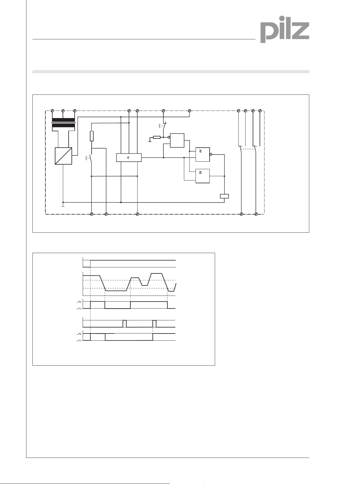
Internal wiring diagram
U
B
~
G1
P1E-2NK(/D)
=
Timing diagram
Measuring circuit
A2A3 A1
R
P
+
S2
TBTB
Test circuit
U
B
B1 B2
R
F1
aRE
E
Reset circuit
RB RB
S1
R
S
P1E-2NK
1
P1E-2NK/D
1
121422 24
K1
K1
11 21
4
R
E
R
off
R
on
11 - 14
1
Reset
0
11 - 14
UBSupply voltage
RonResponse value
non-latching
latching
R
Release value
off
REInsulation resistance
NSG-D-2-225-05/00
Page 3

Electronic Monitoring Relays
Earth fault monitoring
P1E-2NK
Connection examples
● Example 1
AC application circuit
L1
N
U
1L2
1L1
PE
B
0V
U
T1
N
F2
A1 A2A311
Typ 1:
Typ 2:
Typ 3:
Typ 4:
Typ 5:
P1E-2NK(/D)
12 142224 RB RB TB
● Example 2
3AC application circuit
L1
L2
L3
1L1
1L2
PE
UB = 24 V AC,
UB = 110 V AC
UB = 110 V AC
UB = 400 V AC
UB = 500 V AC
U
B
0V
E
21
42 V AC
, 230 V AC
, 240 V AC
U
E
N
B2
B1
E1
TB
R
E
R
E
4
T1
U
NUN
F2
E
E
A1 A2A311
UB = 24 V AC,
Typ 1:
UB = 110 V AC
Typ 2:
UB = 110 V AC
Typ 3:
UB = 400 V AC
Typ 4:
UB = 500 V AC
Typ 5:
P1E-2NK(/D)
12 142224 RB RB TB
21
42 V AC
, 230 V AC
, 240 V AC
B2
B1
R
E1
TB
R
E
E
NSG-D-2-225-05/00
Page 4

Electronic Monitoring Relays
Earth fault monitoring
P1E-2NK
● Example 3
DC application circuit
L1
N
U
B
1L1
0V
1L2
PE
T1
~
G1
=
U
N
F2
U
E
E
A1 A2A311
UB = 24 V AC,
Typ 1:
UB = 110 V AC
Typ 2:
UB = 110 V AC
Typ 3:
UB = 400 V AC
Typ 4:
UB = 500 V AC
Typ 5:
P1E-2NK(/D)
12 142224 RB RB TB
21
42 V AC
, 230 V AC
, 240 V AC
N
B2
B1
E1
TB
R
E
R
E
4
● Example 4
3AC/DC application circuit
L1
L2
L3
U
B
1L1
0V
1L2
PE
A1 A2A311
UB = 24 V AC,
Typ 1:
UB = 110 V AC
Typ 2:
UB = 110 V AC
Typ 3:
UB = 400 V AC
Typ 4:
UB = 500 V AC
Typ 5:
P1E-2NK(/D)
12 142224 RB RB TB
E
21
42 V AC
, 230 V AC
, 240 V AC
alternativ
alternative
U
T1
F2
G1
E
B2
B1
R
E
U
N
E1
TB
N
R
E
NSG-D-2-225-05/00
Page 5

Electronic Monitoring Relays
Earth fault monitoring
P1E-2NK
General Details
Unless stated otherwise in the technical details for the specific unit.
Electrical data
AC frequency range 50 ... 60 Hz
DC residual ripple 160 %
Contact material AgCdO
Continuous duty 100 %
Environmental data
EMC EN 50 081-1, 01/92; EN 50.082-2, 03/95
Vibration in accordance Frequency: 10 ... 55 Hz,
with EN 60068-2-6, 04/95 Amplitude: 0.35 mm
Climatic suitability IEC 60068-2-3, 1969
Airgap creepage DIN VDE 0110-1, 04/97
Ambient temperature -10 ... +55 °C
Storage temperature -40 ... +85 °C
Mechanical data
Torque setting for connection terminals 0.6 Nm (screws)
Mounting position Any
Housing material Thermoplastic Noryl SE 100
Protection types Mounting: IP 54
Housing: IP 40
Terminals: IP 20
Order references key
U
Supply voltage
B
R
Internal resistance
i
D Normally de-energised mode
* Normally energised mode
Order references
Type D/* U
P1E-2NK D 230/110 V 15-100 kW/2C/O 484 105
P1E-2NK D 230/110 V 15-100 kW/2C/O with display 484 104
P1E-2NK * 230/110 V 15-100 kW/2C/O 484 101
P1E-2NK * 230/110 V 15-100 kW/2C/O with display 484 102
P1E-2NK * 24/42 V 15-100 kW2C/O 484 106
P1E-2NK * 24/42 V 15-100 kW/2C/O with display 484 103
P1E-2NK * 240/110 V 15-100 kW/2C/O 484 108
P1E-2NK * 400/110 V 15-100 kW/2C/O 484 112
P1E-2NK * 400/110 V 15-100 kW/2C/O 484 113
Additional versions available on request
B
R
i
Display Order no.
4
NSG-D-2-225-05/00
 Loading...